SENA TECHNOLOGIES IW05 Bluetooth Module User Manual Contents
Sena Technologies,Inc. Bluetooth Module Contents
UserManual.wiki
>
SENA TECHNOLOGIES
>
IW05 User Manual
User Manual
Navigation menu
Upload a User Manual
Namespaces
Wiki Guide
HTML
PDF
Info
Views
User Manual
Discussion / Help
Navigation


![15 Example of remote configuration mode. 3.6. Software and Utility This configuration software and utility for firmware update is included with the product, which also can be downloaded from http://www.senaindustrial.com Table 3-3 Configuration Software Software Purpose Operating System ParaniWIN Configuration MS Windows 98SE or Higher ParaniWizard Pairing Configuration MS Windows 98SE or Higher ParaniMultiWizard Multi Configuration MS Windows 98SE or Higher ParaniUpdater Firmware Update MS Windows 98SE or Higher 3.7. ParaniWIN ParaniWIN is a program that runs on Microsoft Windows for the configuration of IW05. Install ParaniWIN on your computer. Connect the serial port of IW05 into the serial port of the computer and turn on the power.(BCD Development Board or RS232 interface board may be required to access the serial port of IW05.) Run ParaniWIN. Figure 3-1 Serial Port Setting Set each option properly and click [Confirm]. If the settings of the IW05 are different from the ParaniWin, an error message will pop up. If the IW05 is in the status of connection, warning message will pop up. Then the current connection can be cancelled by [Disconnect] button on the main window. CONNECT 000195000001 +++ Please Enter Password AT+PASS=0000 Remote Configuration Enabled AT+BTINFO? 000195000001,BCDx10v2.0.6-095515,MODE0,CONNECT,0,0,HWFC](https://usermanual.wiki/SENA-TECHNOLOGIES/IW05/User-Guide-3257862-Page-15.png)
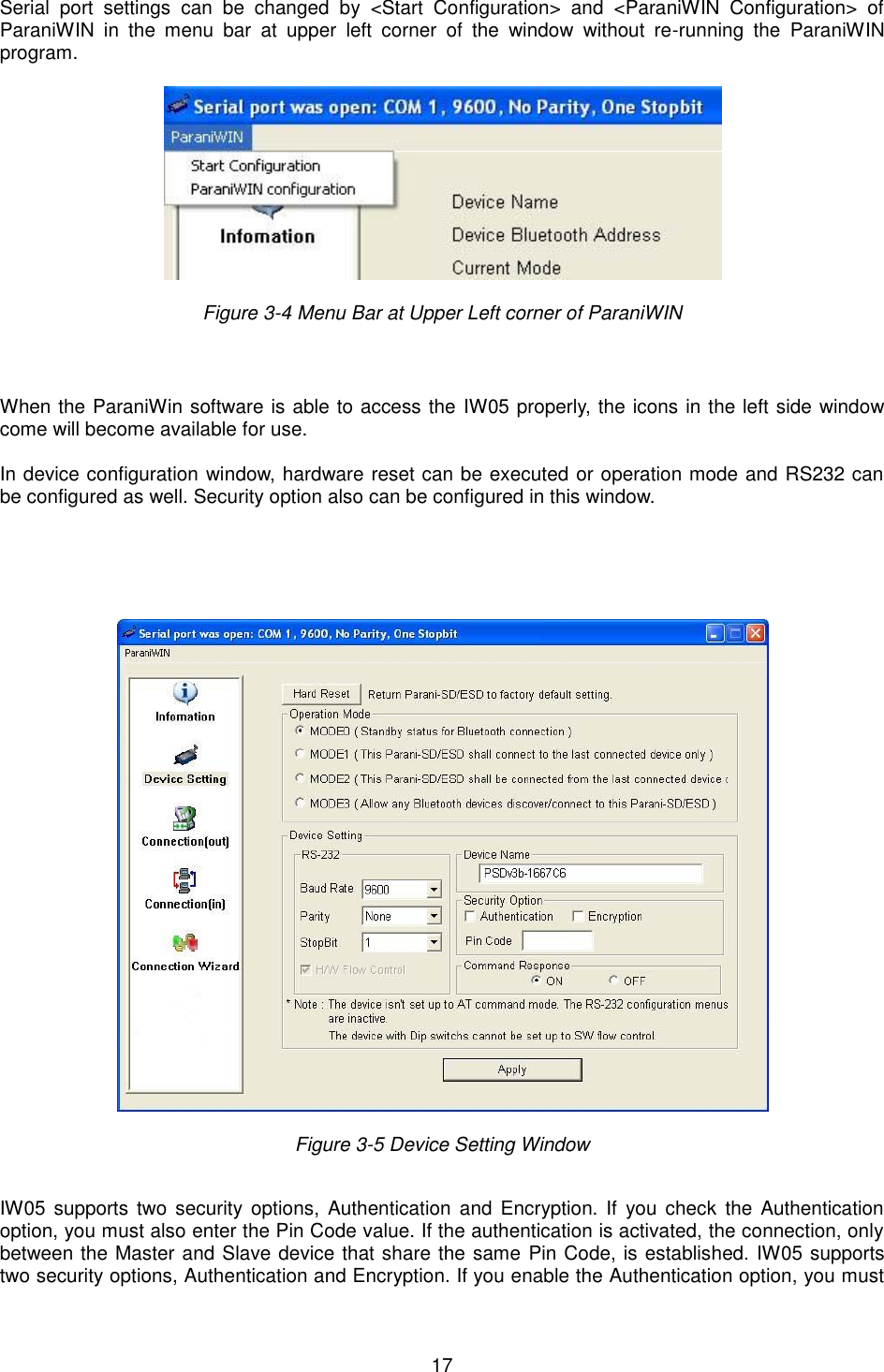
![18 also enter a Pin Code value. If the authentication is enabled, the connection, between the Master and Slave device must share the same Pin Code. In case that IW05 connects to another Bluetooth device, that requires authentication, you must know the other device’s Pin Code. In general, most Bluetooth devices have a pincode of 1234 or 0000. If you check Encryption option, the IW05 will encrypt packets and sent to the device. The Encryption options works well in case that only one of the devices between Master and Slave use the Encryption option. IW05 has 4 response messages, ‘OK’, ‘ERROR’, ‘CONNECT’, and ‘DISCONNECT’. In some cases, these responses can affect the host system unexpectedly. To prevent this, user can set the Command response to ON or OFF. Click [Apply] button to apply any changes made to the IW05. Connection(out) icon will show the following window to search and connect other Bluetooth devices. Figure 3-6 Connection(out) Window Click [Search] button to search nearby Bluetooth devices. Once several Bluetooth devices has been found, select one of the devices and click the [Connect] button. The selected Bluetooth device must be discoverable and connectable. Click [Disconnect] button to cancel the connection. After the connection has been established, you will be able to test signal strength by pushing the START button.](https://usermanual.wiki/SENA-TECHNOLOGIES/IW05/User-Guide-3257862-Page-18.png)
![19 Figure 3-7 Signal Strength Test The signal strength test shows LInkQuality and RSSI values. The closer LinkQuality is to 255 and RSSI is to 0, this means the IW05 has a good connection to the connected Bluetooth device. In general, the wireless connectivity is at its best within 10 meters. You can push the STOP button at any time in order to terminate the signal strength test. The signal strength test will continue until the STOP button is pushed. If you close the ParaniWIN Window without pushing the STOP button, you must restart IW05 to terminate the test. Connection(in) icon will show the following window, which enables the IW05 to wait for a connection from another Bluetooth device. If the waiting time is set to 0, IW05 will continually wait for connection until [Cancel] button is clicked.](https://usermanual.wiki/SENA-TECHNOLOGIES/IW05/User-Guide-3257862-Page-19.png)
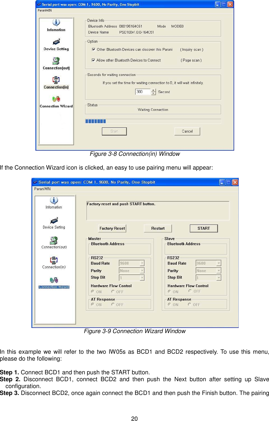
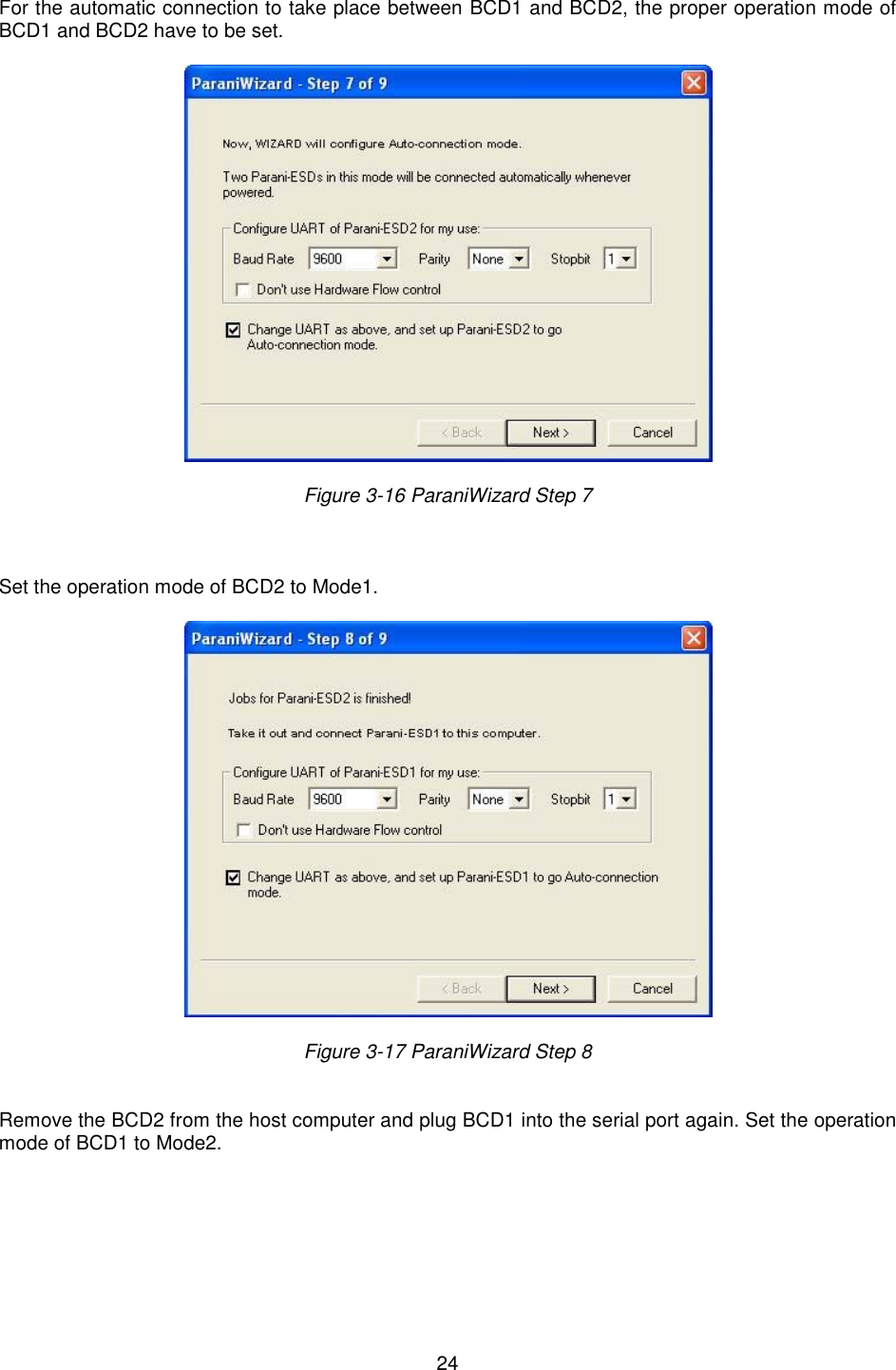
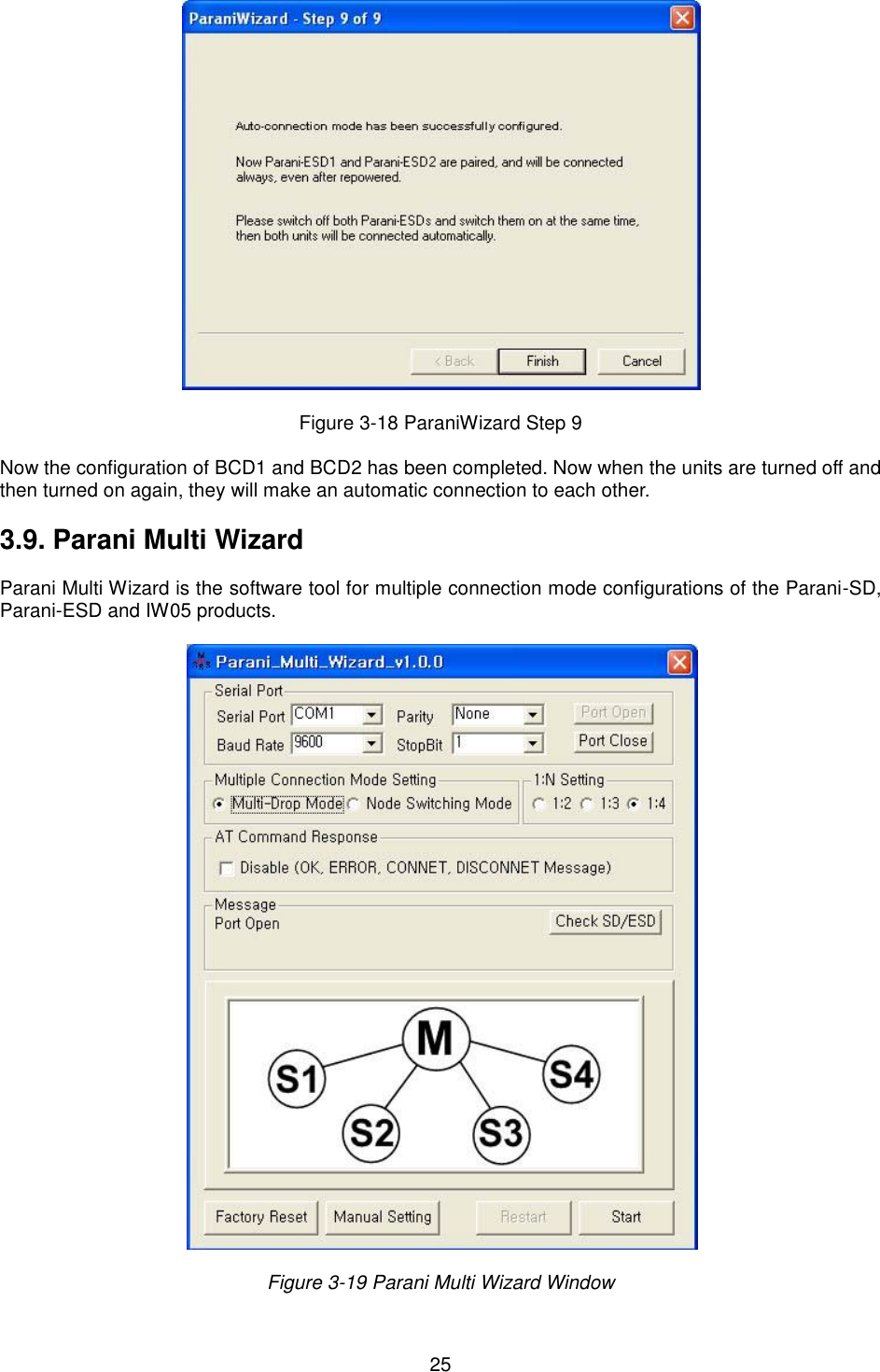
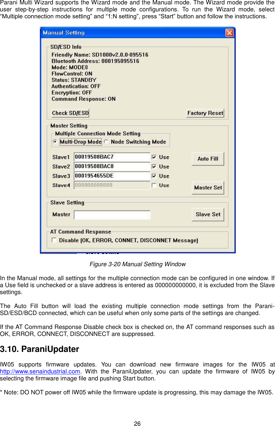
![21 configuration should be completed. Make sure that each IW05’s connect LED is on. At this point, when both IW05s are restarted the connection will be established automatically. 3.8. ParaniWizard ParaniWizard is a Wizard program that will allow you to configure a pair of IW05s for an automatic connection. To make connection with Bluetooth devices other than IW05, use ParaniWIN or AT commands on a terminal program. In this example, we will refer to the two IW05s as BCD1 and BCD2 respectively. Install and run ParaniWizard. Figure 3-10 ParaniWizard Step 1 Plug BCD1 into the serial port of the host computer and power on the unit. Click [Wizard Setting] button to configure the serial port settings of BCD1. These settings must be the same as those of the host system, to which BCD1 will be used. Click [Next]. Figure 3-11 ParaniWizard Step 2](https://usermanual.wiki/SENA-TECHNOLOGIES/IW05/User-Guide-3257862-Page-21.png)
![22 Click [Next] with after selecting the check box, which makes the unit discoverable, in which BCD1 can be discovered and connected from the other Bluetooth device. Remove BCD1 from the host computer, remember to leave the BCD1 powered on. Now, plug BCD2 into the serial port of the host computer and power on the unit. Figure 3-12 ParaniWizard Step 3 Click [Wizard Setting] button to configure the serial settings of BCD2. These settings must be same as those of the host system, to which BCD2 will be used. Click [Next]. Figure 3-13 ParaniWizard Step 4 Click [Next] after selecting check box. BCD2 will then do a search nearby, and search for Bluetooth](https://usermanual.wiki/SENA-TECHNOLOGIES/IW05/User-Guide-3257862-Page-22.png)
![23 devices for 30 seconds. The program will show the Bluetooth devices with Device Address, Device Name and CoD(Class of Device). Figure 3-14 ParaniWizard Step 5 Select the BCD1 from the list and click [Connect], then the following message box will be displayed. Figure 3-15 ParaniWizard Step 6 It may take about 5 seconds to complete the connection.](https://usermanual.wiki/SENA-TECHNOLOGIES/IW05/User-Guide-3257862-Page-23.png)