SENA TECHNOLOGIES IW06 Bluetooth Module User Manual Contents
Sena Technologies,Inc. Bluetooth Module Contents
UserManual.wiki
>
SENA TECHNOLOGIES
>
IW06 User Manual
User Manual
Navigation menu
Upload a User Manual
Namespaces
Wiki Guide
HTML
PDF
Info
Views
User Manual
Discussion / Help
Navigation

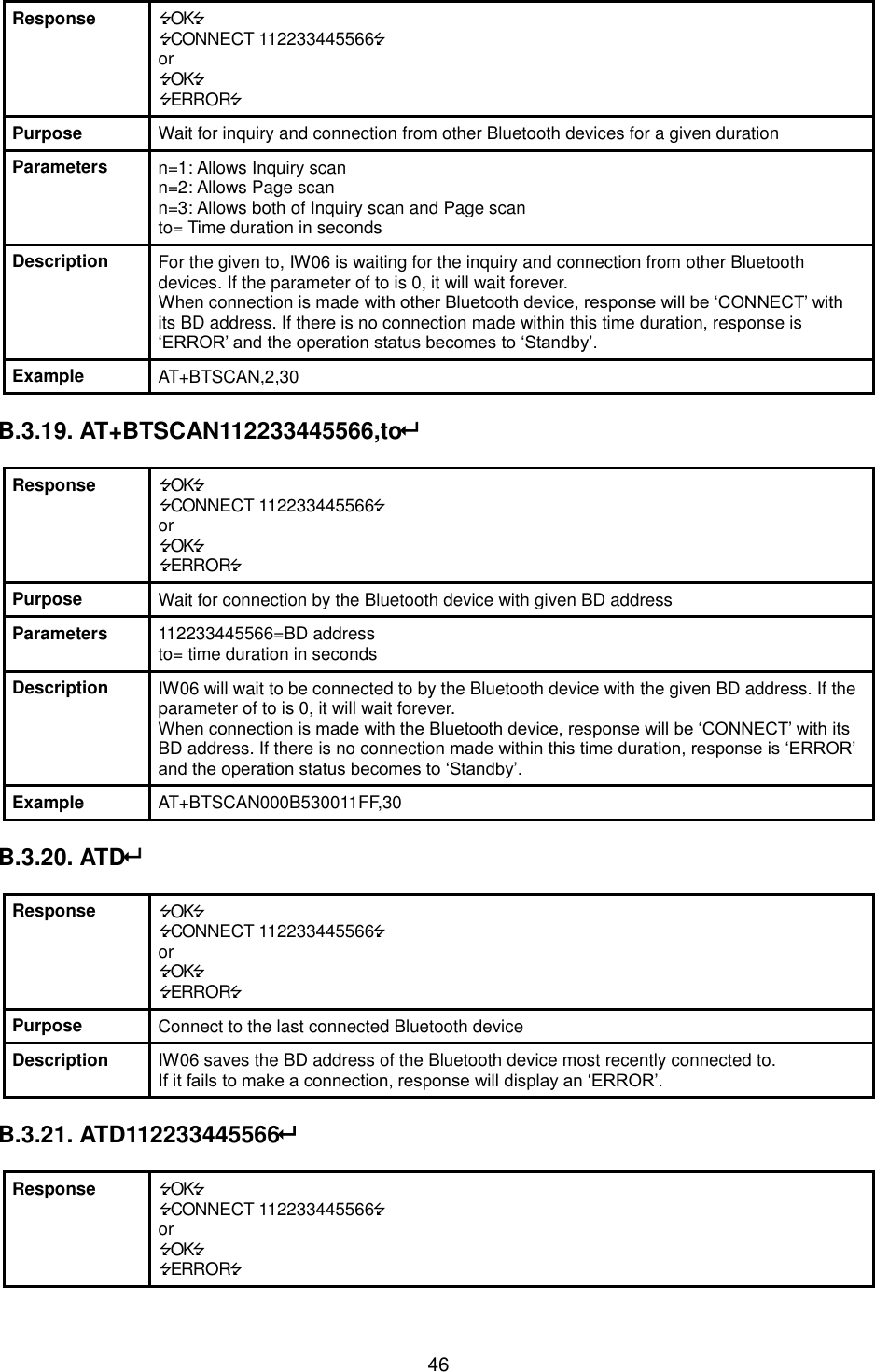
![14 Example of remote configuration mode. 3.6. Software and Utility This configuration software and utility for firmware update is included with the product, which also can be downloaded from http://www.senaindustrial.com Table 3-3 Configuration Software Software Purpose Operating System ParaniWIN Configuration MS Windows 98SE or Higher ParaniWizard Pairing Configuration MS Windows 98SE or Higher ParaniMultiWizard Multi Configuration MS Windows 98SE or Higher ParaniUpdater Firmware Update MS Windows 98SE or Higher 3.7. ParaniWIN ParaniWIN is a program that runs on Microsoft Windows for the configuration of IW06. Install ParaniWIN on your computer. Plug a IW06 into the serial port of the computer and turn on the power. Run ParaniWIN. Figure 3-1 Serial Port Setting Set each option properly and click [Confirm]. If the settings of the IW06 are different from the ParaniWin, an error message will pop up. If the IW06 is in the status of connection, warning message will pop up. Then the current connection can be cancelled by [Disconnect] button on the main window. CONNECT 000195000001 +++ Please Enter Password AT+PASS=0000 Remote Configuration Enabled AT+BTINFO? 000195000001,SD1000v2.0.3-095515,MODE0,CONNECT,0,0,HWFC](https://usermanual.wiki/SENA-TECHNOLOGIES/IW06/User-Guide-3236387-Page-14.png)
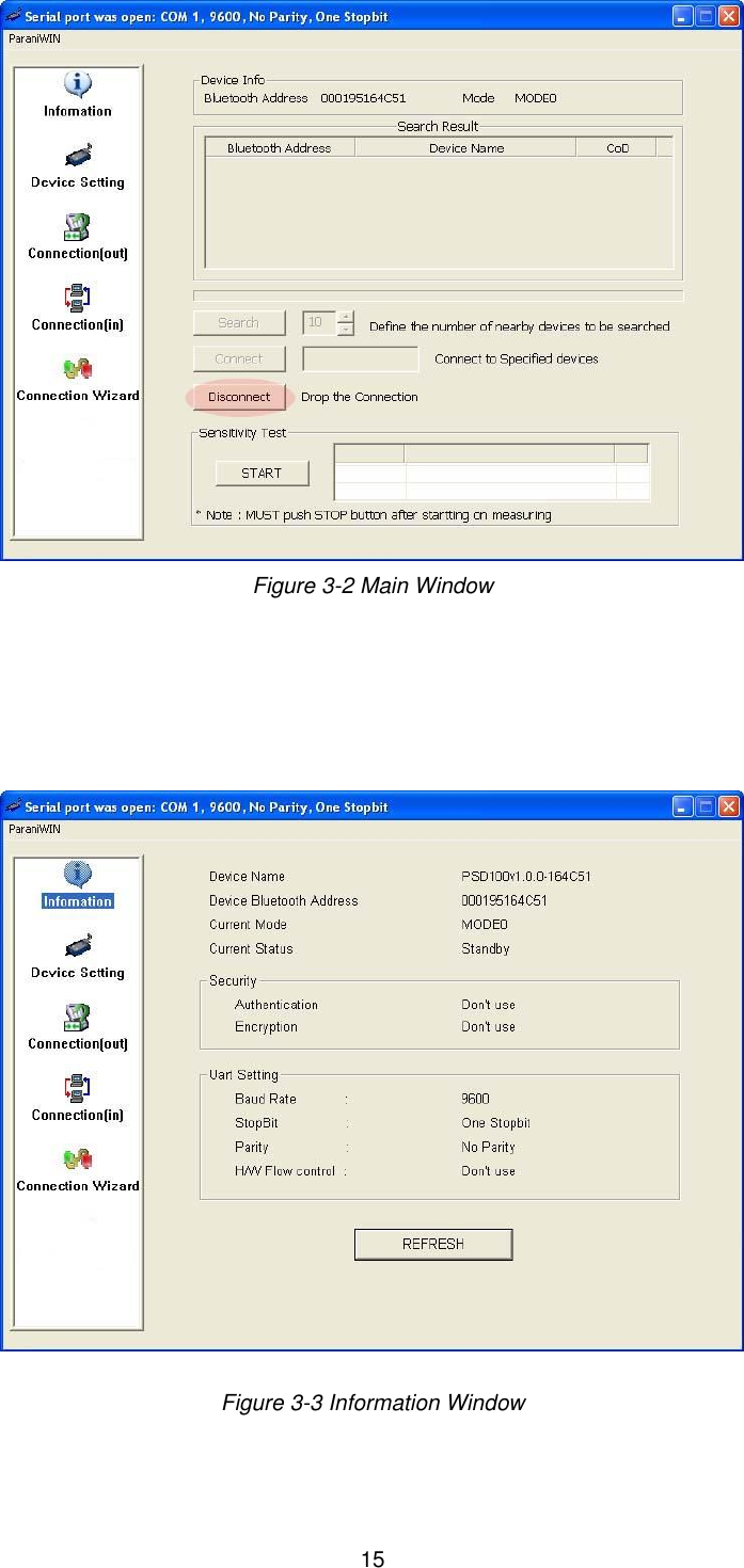
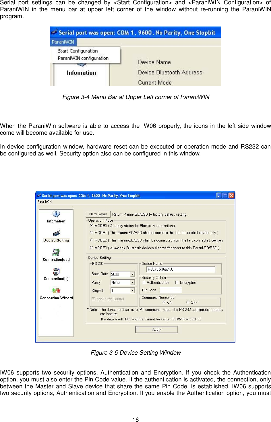
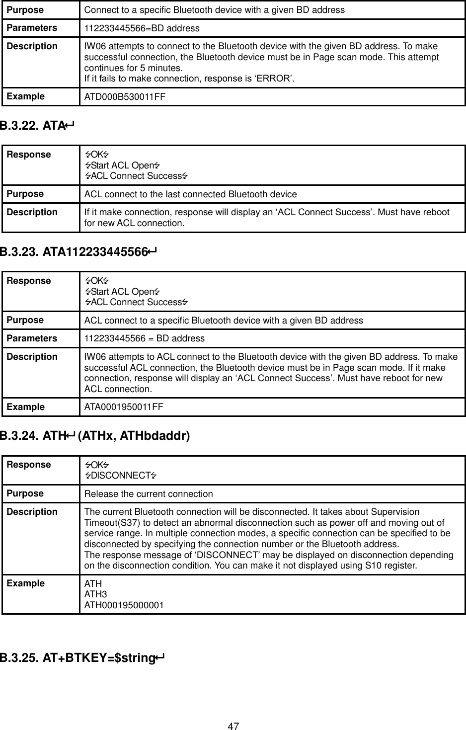
![17 also enter a Pin Code value. If the authentication is enabled, the connection, between the Master and Slave device must share the same Pin Code. In case that IW06 connects to another Bluetooth device, that requires authentication, you must know the other device’s Pin Code. In general, most Bluetooth devices have a pincode of 1234 or 0000. If you check Encryption option, the IW06 will encrypt packets and sent to the device. The Encryption options works well in case that only one of the devices between Master and Slave use the Encryption option. IW06 has 4 response messages, ‘OK’, ‘ERROR’, ‘CONNECT’, and ‘DISCONNECT’. In some cases, these responses can affect the host system unexpectedly. To prevent this, user can set the Command response to ON or OFF. Click [Apply] button to apply any changes made to the IW06. Connection(out) icon will show the following window to search and connect other Bluetooth devices. Figure 3-6 Connection(out) Window Click [Search] button to search nearby Bluetooth devices. Once several Bluetooth devices has been found, select one of the devices and click the [Connect] button. The selected Bluetooth device must be discoverable and connectable. Click [Disconnect] button to cancel the connection. After the connection has been established, you will be able to test signal strength by pushing the START button.](https://usermanual.wiki/SENA-TECHNOLOGIES/IW06/User-Guide-3236387-Page-17.png)
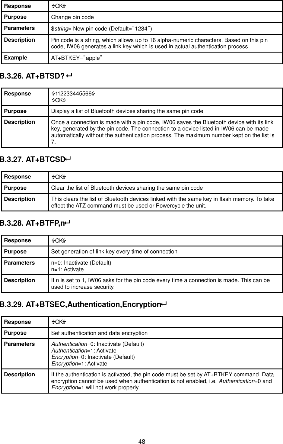
![18 Figure 3-7 Signal Strength Test The signal strength test shows LInkQuality and RSSI values. The closer LinkQuality is to 255 and RSSI is to 0, this means the IW06 has a good connection to the connected Bluetooth device. In general, the wireless connectivity is at its best within 10 meters. You can push the STOP button at anytime in order to terminate the signal strength test. The signal strength test will continue until the STOP button is pushed. If you close the ParaniWIN Window without pushing the STOP button, you must restart IW06 to terminate the test. Connection(in) icon will show the following window, which enables the IW06 to wait for a connection from another Bluetooth device. If the waiting time is set to 0, IW06 will continually wait for connection until [Cancel] button is clicked.](https://usermanual.wiki/SENA-TECHNOLOGIES/IW06/User-Guide-3236387-Page-18.png)
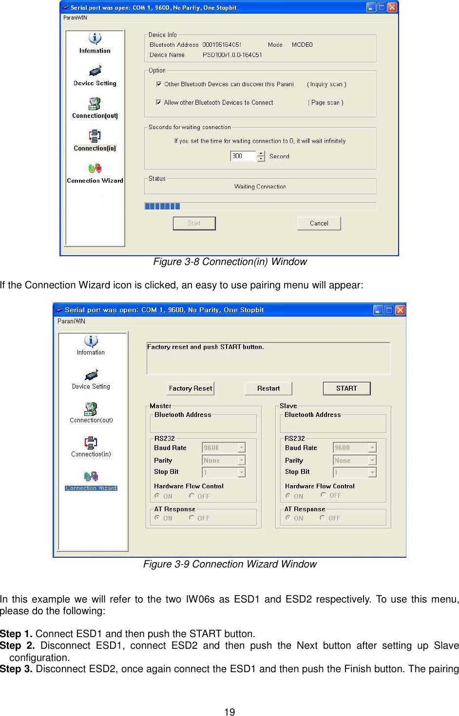
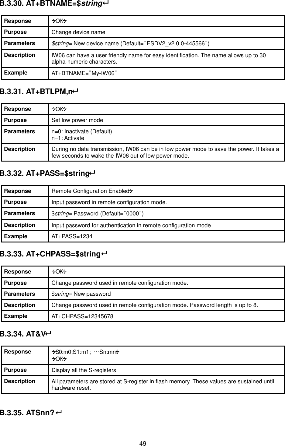
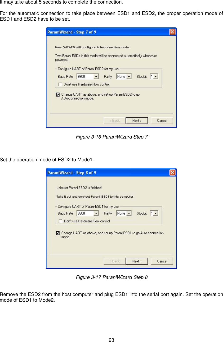
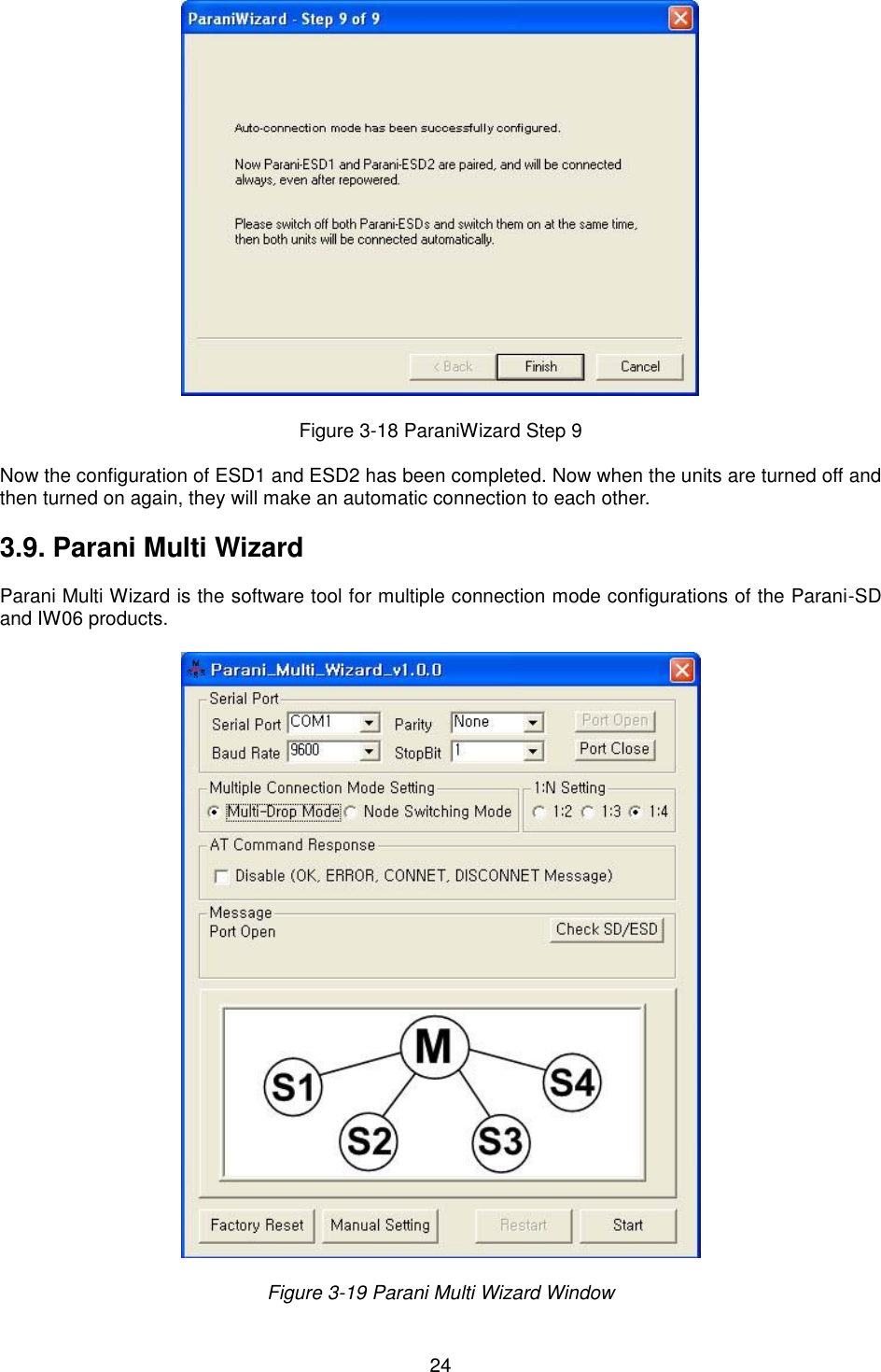
![20 configuration should be completed. Make sure that each IW06’s connect LED is on. At this point, when both IW06’s are restarted the connection will be established automatically. 3.8. ParaniWizard ParaniWizard is a Wizard program that will allow you to configure a pair of IW06’s for an automatic connection. To make connection with Bluetooth devices other than IW06, use ParaniWIN or AT commands on a terminal program. In this example, we will refer to the two IW06’s as ESD1 and ESD2 respectively. Install and run ParaniWizard. Figure 3-10 ParaniWizard Step 1 Plug ESD1 into the serial port of the host computer and power on the unit. Click [Wizard Setting] button to configure the serial port settings of ESD1. These settings must be the same as those of the host system, to which ESD1 will be used. Click [Next]. Figure 3-11 ParaniWizard Step 2](https://usermanual.wiki/SENA-TECHNOLOGIES/IW06/User-Guide-3236387-Page-20.png)
![21 Click [Next] with after selecting the check box, which makes the unit discoverable, in which ESD1 can be discovered and connected from the other Bluetooth device. Remove ESD1 from the host computer, remember to leave the ESD1 powered on. Now, plug ESD2 into the serial port of the host computer and power on the unit. Figure 3-12 ParaniWizard Step 3 Click [Wizard Setting] button to configure the serial settings of ESD2. These settings must be same as those of the host system, to which ESD2 will be used. Click [Next]. Figure 3-13 ParaniWizard Step 4](https://usermanual.wiki/SENA-TECHNOLOGIES/IW06/User-Guide-3236387-Page-21.png)
![22 Click [Next] after selecting check box. ESD2 will then do a search nearby, and search for Bluetooth devices for 30 seconds. The program will show the Bluetooth devices with Device Address, Device Name and CoD (Class of Device). Figure 3-14 ParaniWizard Step 5 Select the ESD1 from the list and click [Connect], then the following message box will be displayed. Figure 3-15 ParaniWizard Step 6](https://usermanual.wiki/SENA-TECHNOLOGIES/IW06/User-Guide-3236387-Page-22.png)
![33 5.2. IC This device complies with Industry Canada license-exempt RSS standard(s). Operation is subject to the following two conditions: (1) this device may not cause interference, and (2) this device must accept any interference, including interference that may cause undesired operation of the device. Le present appareil est conforme aux CNR d'Industrie Canada applicables aux appareils radio exempts de licence. L'exploitation est autorisee aux deux conditions suivantes : (1) l'appareil ne doit pas produire de brouillage, et. (2) l'utilisateur de l'appareil doit accepter tout brouillage radio electrique subi, meme si le brouillage est susceptible d'en compromettre le fonctionnement. The antenna must be installed so as to maintain at all times a distance minimum of at least 20 cm between the radiation source and any individual. This device may not be installed or used in conjunction with any other antenna or transmitter. L’antenne doit être installée de façon à maintenir à tout instant une distance minimum de au moins 20 cm entre la source de radiation et toute personne physique. Cet appareil ne peut pas être installé ou utilisé avec une autre antenne ou émetteur. This radio transmitter (Model: IW06) has been approved by Industry Canada to operate with the antenna types listed below with the maximum permissible gain indicated. Antenna types not included in this list, having a gain greater than the maximum gain indicated for that type, are strictly prohibited for use with this device. Cet émetteur radio (modèle: IW 06) a été approuvé par Industrie Canada pour fonctionner avec les types d'antennes répertoriés ci-dessous avec le gain maximal autorisé indiqué. Les types d'antennes non inclus dans cette liste, ayant un gain supérieur au gain maximal indiqué pour ce type, sont strictement interdits pour une utilisation avec cet appareil. Type Frequency[MHz] Max gain[dBi] Dipole antenna 2402~2480 5.70 Chip antenna 2402~2480 1.00 *In case of dipole antenna, it is maximum gain 5.2dBi including cable loss. É tiquetage du produit final (IC) Le module est étiqueté avec sa propre identification FCC et son propre numéro de certification IC. Si l’identification FCC et le numéro de certification IC ne sont pas visibles lorsque le module est installé à l’intérieur d’un autre dispositif, la partie externe du dispositif dans lequel le module est installé devra également présenter une étiquette faisant référence au module inclus. Dans ce cas, le produit final devra être étiqueté sur une zone visible avec les informations suivantes : « Contient module émetteur identification FCC ID : S7A-IW06 « Contient module émetteur IC : 8154A-IW06 5.3. CE Hereby, SENA TECHNOLOGIES.Inc Declares that this IW07 is in compliance with the essential requirements and other relevant provisions of directive 1999/5/EC.](https://usermanual.wiki/SENA-TECHNOLOGIES/IW06/User-Guide-3236387-Page-33.png)