SENA TECHNOLOGIES IW06 Bluetooth Module User Manual Contents
Sena Technologies,Inc. Bluetooth Module Contents
User Manual
Model: IW06
User Guide
Version 2.0.6.2
2016-10-29

2
User Guide for the IW06
Version 2.0.6.1
Firmware version 2.0.X
Printed in Korea
Copyright
Copyright 2008~2015, Sena Technologies, Inc. All rights reserved.
Sena Technologies reserves the right to make changes and improvements to its product without
providing notice.
Trademark
Parani™ is a trademark of Sena Technologies, Inc.
Windows® is a registered trademark of Microsoft Corporation.
Ethernet® is a registered trademark of XEROX Corporation.
Notice to Users
When a system failure may cause serious consequences, protecting life and property against such
consequences with a backup system or safety device is essential. The user agrees that protection
against consequences resulting from system failure is the user's responsibility.
This device is not approved for life-support or medical systems.
Changes or modifications to this device not explicitly approved by Sena Technologies will void the
user's authority to operate this device.
Precautions and Safety
Electricity
Use only the supplied AC adapter. Use of unauthorized power adapter is not recommended. Electrical
shock may result.
Do not kink or crease the power cable or place heavy objects on the power cable. Fire can result from
damaged power cables.
Do not handle power plug and adapter with wet hands. Electrical shock may result.
Immediately power off the product and unplug the AC adapter if smoke or odors emit from the product
and adapter. Fire can result from improper use.
Immediately power off the product and unplug the AC adapter if water or other liquids are present. Fire
can result from improper use.
Product
IW06 meets the RS-232 standards. Do not wire with non-standard products. Damage to your products
may result from improper use.
Do not drop or subject the device to impact. Damage to your products may result from improper use.
Keep away from harsh environments including humid, dusty, and smoky areas. Damage to your
products may result from improper use.
Do not use excessive force on the buttons or attempt to disassemble the device. Damage to your
products may result from improper use.
Do not place heavy objects on the product. Damage to your products may result from improper use.
Technical Support
Sena Technologies, Inc.
Tel: (+82-2) 576-7362
Fax: (+82-2) 573-7710
E-Mail: support@senaindustrial.com
Website: http://www.senaindustrial.com

3
Revision History
Revision
Date
Name
Description
V1.0.0
2009-09-29
Yh Moon
Initial Revision History
V2.0.0
2009-11-19
Yh Moon
Multiple connection mode
V2.0.2
2010-05-04
Yh Moon
Add a Parani Multi Wizard
V2.0.3
2010-09-03
Yh Moon
Update Table 3-3
V2.0.4
2011-01-31
Jh Park
Add remote configuration
V2.0.4.1
2011-12-26
HR Zo
Package does not contain CD-ROM
V2.0.5
2012-01-18
Jh Park
Modify contents about page timeout and
node switching mode
V2.0.6
2012-02-24
Jh Park
Modify AT+MULTI command of response
V2.0.6.1
2015-09-10
TM Kim
Change the website address
4
Contents
1. Introduction 7
1.1. Overview .................................................................................................................................... 7
1.2. Package Check List ................................................................................................................... 7
1.2.1. Single/Bulk Unit Package ................................................................................................. 7
1.2.2. Starter Kit ......................................................................................................................... 7
1.3. Product Specification ................................................................................................................. 8
2. Getting Started 9
2.1. Panel Layout .............................................................................................................................. 9
2.2. Connecting the Hardware .......................................................................................................... 9
2.2.1. Connecting IW06 to Development Board ...................................................................... 10
2.2.2. Connecting Power to Development Board ..................................................................... 10
2.2.3. Connecting a Device to Development Board ................................................................. 11
3. Configuration 12
3.1. Operation Modes ...................................................................................................................... 12
3.2. Serial Ports ............................................................................................................................... 13
3.3. Data Bit ..................................................................................................................................... 13
3.4. Hardware Flow Control ............................................................................................................ 13
3.5. Remote Configuration .............................................................................................................. 13
3.6. Software and Utility .................................................................................................................. 14
3.7. ParaniWIN ................................................................................................................................ 14
3.8. ParaniWizard ............................................................................................................................ 20
3.9. Parani Multi Wizard .................................................................................................................. 24
3.10. ParaniUpdater ........................................................................................................................ 25
3.11. Terminal Program ................................................................................................................... 26
4. Multiple Connection Mode 28
4.1. Overview .................................................................................................................................. 28
4.2. Configuration ............................................................................................................................ 29
4.3. AT Commands .......................................................................................................................... 30
4.3.1. AT+MULTI,n ................................................................................................................... 30
4.3.2. AT+MLIST? .................................................................................................................... 30
4.3.3. ATHx, ATHbdaddr .......................................................................................................... 30
4.3.4. ATOx, ATObdaddr ......................................................................................................... 30
4.4. Notes ........................................................................................................................................ 31
5. Approval Information 32
6. Approval Information 오류! 책갈피가 정의되어 있지 않습니다.
6.1. FCC ............................................................................ 오류! 책갈피가 정의되어 있지 않습니다.
6.1.1. FCC Compliance Statement ............................ 오류! 책갈피가 정의되어 있지 않습니다.
6.1.2. RF Exposure Statement ................................... 오류! 책갈피가 정의되어 있지 않습니다.
6.1.3. Do not ............................................................... 오류! 책갈피가 정의되어 있지 않습니다.
7. RF Information 34
7.1. Radio Frequency Range .......................................................................................................... 34
7.2. Number of Frequency Channel ................................................................................................ 34
7.3. Transmission Method ............................................................................................................... 34
7.4. Modulation Method ................................................................................................................... 34
7.5. Radio Output Power ................................................... 오류! 책갈피가 정의되어 있지 않습니다.
7.6. Receiving Sensitivity ................................................................................................................ 34
7.7. Power Supply ........................................................................................................................... 34
Appendix A: Connections 35
A.1. Pin Assignment ........................................................................................................................ 35
A.1.1. IW06 .............................................................................................................................. 35
A.1.2. DCD Signal (Status: Bluetooth Connect Detect) ........................................................... 35
A.1.3. Factory Reset Signal ..................................................................................................... 36
A.1.4. Pairing (BT_MODE) Signal (Single Connection Mode Only) ........................................ 36
A.2. Connection Diagram ................................................................................................................ 37
5
A.2.1. IW06 .............................................................................................................................. 37
Appendix B: AT Commands 40
B.1. Terminology .............................................................................................................................. 40
B.1.1. AT Command ................................................................................................................. 40
B.1.2. AT Response ................................................................................................................. 40
B.1.3. Operation Mode ............................................................................................................. 40
B.1.4. Operation Status ............................................................................................................ 40
B.1.5. Security .......................................................................................................................... 40
B.1.6. Symbols ......................................................................................................................... 40
B.2. Command Category ................................................................................................................. 41
B.3. Command Description ............................................................................................................. 42
B.3.1. ATZ .............................................................................................................................. 42
B.3.2. AT&F ............................................................................................................................ 42
B.3.3. AT ................................................................................................................................. 42
B.3.4. AT+UARTCONFIG,Baudrate,Parity,Stopbit,Hwfc ........................................................ 42
B.3.5. AT+BTINFO? ............................................................................................................... 42
B.3.6. AT+BTINQ?.................................................................................................................. 43
B.3.7. AT+BTLAST? ............................................................................................................... 43
B.3.8. AT+BTVER? ................................................................................................................ 43
B.3.9. AT+BTRSSI,n(Single Connection Mode Only) ............................................................ 43
B.3.10. AT+MLIST? ................................................................................................................ 44
B.3.11. AT+BTMODE,n .......................................................................................................... 44
B.3.12. AT+MULTI,n ............................................................................................................... 44
B.3.13. +++............................................................................................................................. 44
B.3.14. AT+SETESC,nn ......................................................................................................... 45
B.3.15. ATO (ATOx, ATObdaddr) ........................................................................................... 45
B.3.16. AT+BTCANCEL ......................................................................................................... 45
B.3.17. AT+BTSCAN .............................................................................................................. 45
B.3.18. AT+BTSCAN,n,to ....................................................................................................... 45
B.3.19. AT+BTSCAN112233445566,to .................................................................................. 46
B.3.20. ATD ............................................................................................................................ 46
B.3.21. ATD112233445566 .................................................................................................... 46
B.3.22. ATA............................................................................................................................. 47
B.3.23. ATA112233445566 ..................................................................................................... 47
B.3.24. ATH (ATHx, ATHbdaddr) ............................................................................................ 47
B.3.25. AT+BTKEY=$string .................................................................................................... 47
B.3.26. AT+BTSD? ................................................................................................................ 48
B.3.27. AT+BTCSD ................................................................................................................ 48
B.3.28. AT+BTFP,n ................................................................................................................. 48
B.3.29. AT+BTSEC,Authentication,Encryption ...................................................................... 48
B.3.30. AT+BTNAME=$string ................................................................................................ 49
B.3.31. AT+BTLPM,n ............................................................................................................. 49
B.3.32. AT+PASS=$string ...................................................................................................... 49
B.3.33. AT+CHPASS=$string ................................................................................................. 49
B.3.34. AT&V .......................................................................................................................... 49
B.3.35. ATSnn? ..................................................................................................................... 49
B.3.36. ATSnn=mm ................................................................................................................ 50
B.4. Command Validity .................................................................................................................... 50
Appendix C: S-Register 52
C.1. S1: Force to Reconnect (default 1).......................................................................................... 52
C.2. S3: Stream UART Policy (default 0) ........................................................................................ 52
C.3. S4: Enable Remote Name Query (default 1) ........................................................................... 52
C.4. S6: Enable Low Power Mode (default 0) ................................................................................. 52
C.5. S10: Enable Response Message (default 1) ........................................................................... 52
C.6. S11: Enable Escape (default 1) ............................................................................................... 52
C.7. S12: Clear Data Buffer When Disconnected (default 0) .......................................................... 53
C.8. S13: Enable DCD Signal (default 1) ........................................................................................ 53
C.9. S14: Enable DTR Transfer (default 1) ..................................................................................... 53
6
C.10. S15: Enable Disconnect by DTR (default 0) .......................................................................... 53
C.11. S22: Faster Connection (default 3) ........................................................................................ 53
C.12. S23: Intercharacter Timeout Setting (default 0) ..................................................................... 53
C.13. S24: Maximum Number of Inquiry Result (default 15) .......................................................... 53
C.14. S26: Intercharacter Timeout (default 0) ................................................................................. 53
C.15. S28: Escape Sequence Character (default 43) ..................................................................... 54
C.16. S31: Page Timeout (default 20) ............................................................................................. 54
C.17. S33: Inquiry Timeout (default 30) .......................................................................................... 54
C.18. S37: Supervision Timeout (default 5) .................................................................................... 54
C.19. S43: COD (default 001F00) ................................................................................................... 54
C.20. S44: COD Filter (default 0) .................................................................................................... 54
C.21. S45: Inquiry Access Code (default 0x9E8B33) ..................................................................... 54
C.22. S46: BD Address of Last Connected Device ......................................................................... 54
C.23. S48: Low Power Max Interval (default 5000) ........................................................................ 55
C.24. S49: Low Power Min Interval (default 4500) ......................................................................... 55
C.25. S52: Low Power Timeout (default 5) ..................................................................................... 55
C.26. S54: BD Address of Last Connected Device ......................................................................... 55
C.27. TS55: BD Address of Last Connected Device ....................................................................... 55
C.28. S56: BD Address of Last Connected Device ......................................................................... 55
C.29. S57: Slave Disconnect Timeout (default 3) ........................................................................... 55
C.30. S58: MAX TX POWER (default 0) ......................................................................................... 55
C.31. S59: Current Slave in Communication (default 0) ................................................................. 56
C.32. S60: Reconnect Time Interval (default 5) .............................................................................. 56
Appendix D: Trouble Shooting 57
D.1. No Data Transmission ............................................................................................................. 57
D.1.1. Device Settings ............................................................................................................. 57
D.2. Data Loss or Malfunctioning .................................................................................................... 57
D.2.1. Hardware Flow Control .................................................................................................. 57
D.2.2. Response Message ....................................................................................................... 57
D.3. Transmission Delay ................................................................................................................. 57
D.3.1. RF Processing Delay ..................................................................................................... 57
D.3.2. RF Transmission Environment ...................................................................................... 57
Appendix E: Warranty 58
E.1. GENERAL WARRANTY POLICY ............................................................................................ 58
E.2. LIMITATION OF LIABILITY ...................................................................................................... 58
E.3. HARDWARE PRODUCT WARRANTY DETAILS .................................................................... 58
E.4. SOFTWARE PRODUCT WARRANTY DETAILS .................................................................... 59
E.5. THIRD-PARTY SOFTWARE PRODUCT WARRANTY DETAILS ............................................ 59
Appendix F: How to make a RS232 interface Development Board 60
Appendix G: IW06 PCB mechanical drawing 61
7
1. Introduction
1.1. Overview
IW06 is a module device for wireless serial communication using Bluetooth technology that is
international a standard for short range wireless communications. IW06 can communicate with other
Bluetooth devices that support the Serial Port Profile.
The working distance of IW06 with default antenna is 100m. The IW06 delivers better quality of
communication than a standard RS232 cables.
IW06 has a compact design and can be placed conveniently into devices or equipment. Its detachable
antenna optimizes the quality and distance for wireless communications.
IW06 supports FHSS (Frequency Hopping Spread Spectrum), which is a technique, native to
Bluetooth that allows the IW06 minimize radio interference while decreasing the likelihood of over-air
hijacking. IW06 also supports authentication and Bluetooth data encryption.
IW06 can be configured and controlled by typical AT commands. Users can easily configure IW06 by
using a terminal program such as HyperTerminal and can use Bluetooth wireless communication
without modifying user’s existing serial communication program. In addition to the basic AT commands,
IW06 provides some expanded AT commands for various functions. User friendly ParaniWizard and
ParaniWIN are also provided for easy setup on Microsoft Windows.
1.2. Package Check List
1.2.1. Single/Bulk Unit Package
IW06
- IW06 Module (on-board chip antenna)
IW06
- IW06 Module
- Stub Antenna
- Antenna extension cable
1.2.2. Starter Kit
- Development board
- Serial data cable
- DC Power Adapter
- A hardcopy of Quick Start Guide

8
1.3. Product Specification
Note *:
Bluetooth v2.0 supports improved AFH function. AFH function is to mitigate the interference
between WiFi and Bluetooth radios by automatically avoiding the active WiFi channel from
Bluetooth link. However, AFH does not provide a complete solution making WiFi and Bluetooth
work together in harmony. It is highly recommended for users to test their wireless system
enough before deployment since the overall system performance is affected by various
environmental factors such as distance between them.
IW06
Serial Interface
Serial UART speed up to 921.6kbps
CTS/RTS flow control, DTR/DSR for loop-back & full transfer
2.54mm Pin Header 2X6 (12pin)
Bluetooth Interface
Bluetooth v2.0 + EDR
Profile: Serial Port Profile
Class 1
Working distance:
- IW06:
Nominal 100m
- IW06:
Ant (AN2400-3306RS) - Ant (AN2400-3306RS) 100 meters
Ant (AN2400-3306RS) - Ant (R-AN2400-5801RS) 150 meters
Ant (R-AN2400-5801RS) - Ant (R-AN2400-5801RS) 200 meters
Ant (R-AN2400-5801RS) - Ant ( R-AN2400-1901RS) 300 meters
Ant (R-AN2400-1901RS) - Ant (R-AN2400-1901RS) 400 meters
Configuration
ParaniWIN, ParaniWizard, Modem AT command set
Firmware Update
ParaniUpdater
Power
Supply voltage: 3.3V DC
Supply current::10mA – 60mA
Environmental
Operating temperature: -30 ~ 80 oC
Storage temperature: -40 ~ 85 oC
Humidity : 90% (Non-condensing)
Physical properties
IW06 Dimension
27.5 mm L (1.08 in )
30.0 mm W (1.18 in )
14.0 mm H (0.55 in )
Weight
6 g
Approvals
FCC, CE, KCC, TELEC, SIG
Warranty
1-year limited warranty
9
2. Getting Started
This chapter describes how to set up the IW06 for the first time.
- 2.1 Panel Layout explains the panel layout.
- 2.2 Connecting the Hardware describes how to connect the IW06, the power, and the serial device
to the Jig Board.
Following items are pre-required to get started.
- One Jig Board (included in the Starter Kit package).
- One DC power adapter or one USB power cable (included in the Starter Kit package).
- One serial console cable for configuration (included in the Starter Kit package).
- One PC with RS232 serial port.
- Terminal emulation program running on the PC
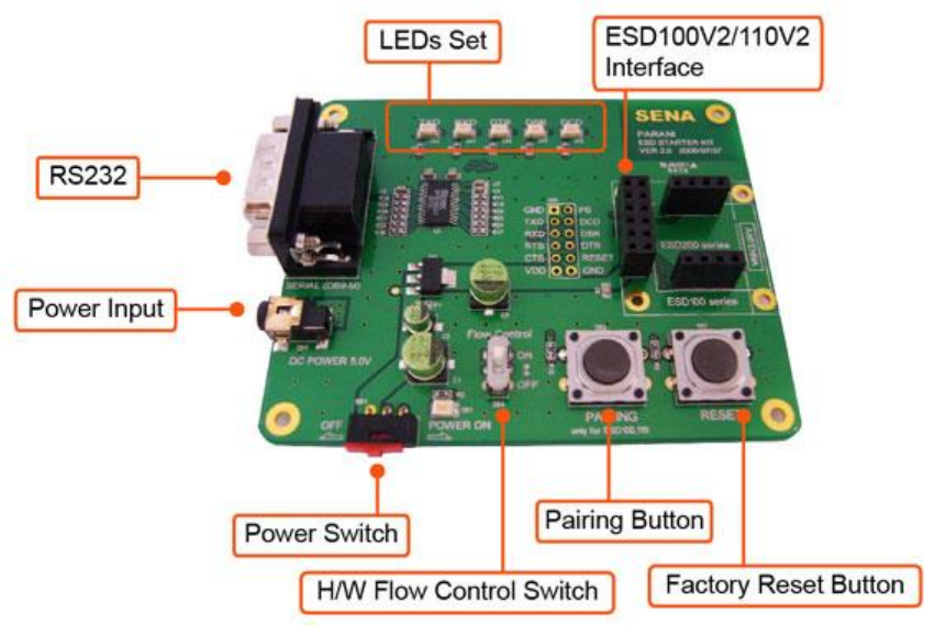
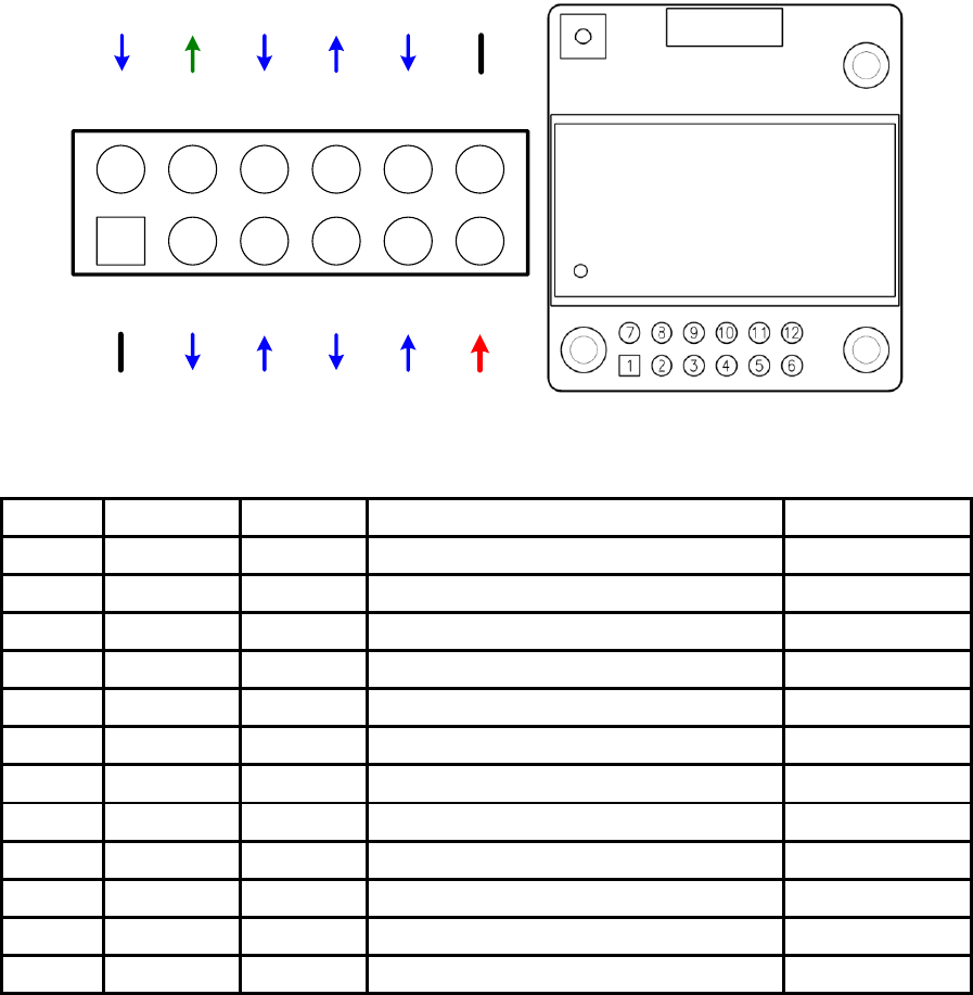
2.1. Panel Layout
This section describes the panel layout of the Development Board.
Figure 2-1 The Panel Layout of Development Board
2.2. Connecting the Hardware
This section describes how to connect the IW06 to the Development Board and the Development
Board to the serial device for initial testing.
- Connect the IW06 to the Development Board.
- Connect a power source to the Development Board for the IW06.
- Connect the Development Board for the IW06 to a serial device.
10
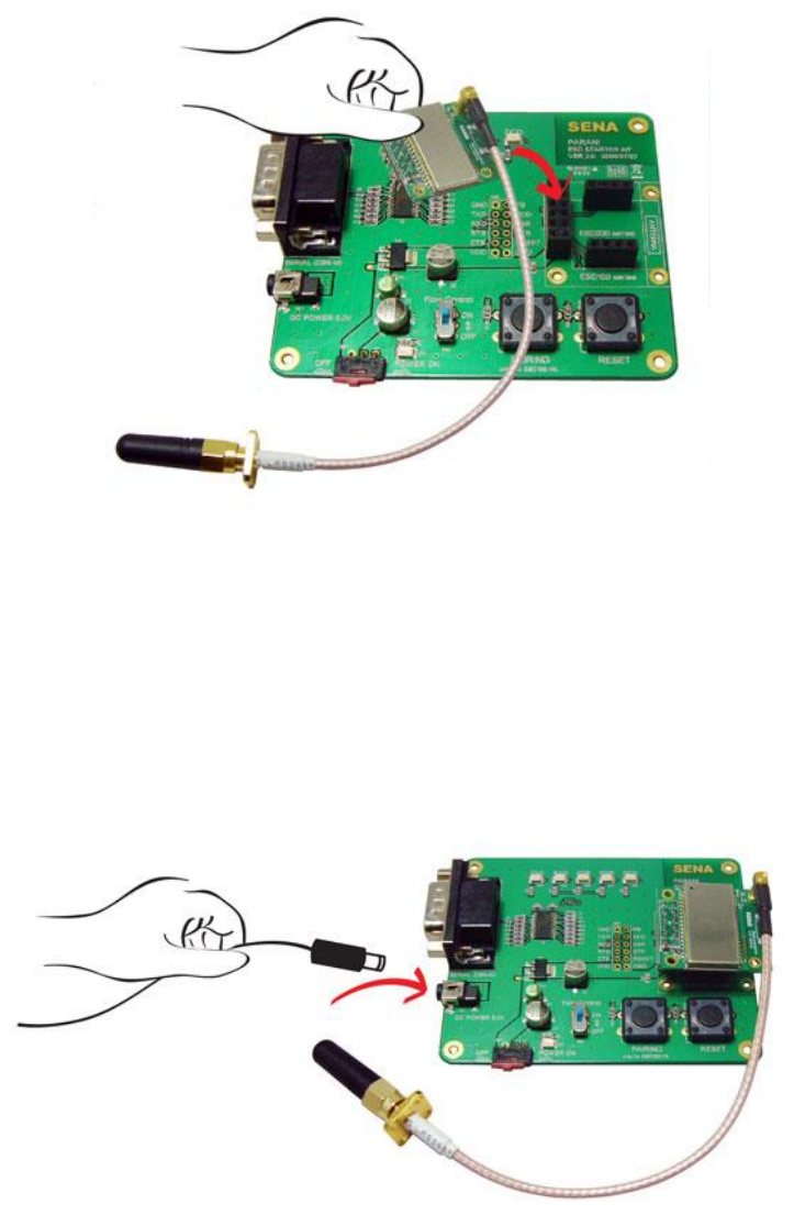
2.2.1. Connecting IW06 to Development Board
Connect the IW06 to the Development Board as shown below.
Figure 2-2 Connecting IW06 to Development Board
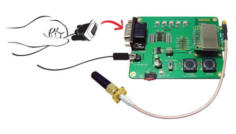
2.2.2. Connecting Power to Development Board
Connect the power plug to the power connector of the Development Board for the IW06 using the DC
power adapter or USB power cable that is included in the package.
Figure 2-3 Connecting Power to Development Board
11
2.2.3. Connecting a Device to Development Board
Connect the serial data cable between the Development Board and the serial device. If necessary,
supply power to the serial device attached to the Development Board.
Figure 2-4 Connecting a Device to Development Board

12
3. Configuration
3.1. Operation Modes
In addition to the serial port configurations, the IW06 requires also includes some settings for
Bluetooth. For getting the most out of IW06, user should understand the following Bluetooth
connection schemes.
A Bluetooth device can play a role as a master or slave. Master tries to connect itself to other
Bluetooth devices, and slave is waiting to be connected from other Bluetooth devices. A Bluetooth
connection is always made by a pair of master and slave devices. A slave can be in two modes,
Inquiry Scan or Page Scan mode. Inquiry Scan mode is waiting for a packet of inquiry from other
Bluetooth device and Page Scan mode is waiting for a packet of connection from other Bluetooth
device. Every Bluetooth device has its unique address, called BD (Bluetooth Device) address, which is
composed of 12 hexa-decimal numbers.
IW06 has 4 operation modes as follows:
Table 3-1 The IW06 Operation Modes
Mode
Description
Mode0
In this mode, there is no response when power on or software reset, and IW06 is just waiting
for AT command input. Neither master nor slave is assigned to IW06 in mode0. User can
change the configuration parameters of IW06 in this mode.
IW06 must be in Mode0, when it is directly controlled by AT commands.
The factory default is set to Mode0.
Mode1
IW06 tries to connect the last connected Bluetooth device.
IW06 in Mode1 is to be a master and tries to connect the last connected Bluetooth device.
IW06 always stores the BD address of the Bluetooth device to which IW06 has connected last.
When IW06 is initially used or after hardware reset, there is no BD address stored in IW06. In
this case, Mode1 will not be able to work properly. The mode change to Mode1 can be made
after IW06 succeeds to connect to one other Bluetooth device. Once changed to Mode1, IW06
will try to connect automatically the last connected Bluetooth device whenever the unit is
powered on or software reset.
IW06 in Mode1 cannot be discovered or connected by other Bluetooth devices.
Mode2
IW06 is waits for a connection from the last connected Bluetooth device.
IW06 in Mode2 is to be a slave and waiting for the connection only from the last connected
Bluetooth device. Just like Mode1, if there is no BD address stored in IW06, the mode change
from other operation modes to Mode2 is not work properly. Once changed to Mode2, IW06 will
wait for the connection from the last connected Bluetooth device whenever the unit is powered
on or software reset.
IW06 in Mode2 cannot be discovered or connected to Bluetooth devices other than the last
connected device.
Mode3
IW06 is waiting for the connection from any other Bluetooth devices. In Mode 3 the IW06 is
discoverable and can be connected to by other Bluetooth devices.

13
3.2. Serial Ports
The applicable settings for serial ports are as follows.
Table 3-2 The IW06 Serial Port Settings
Serial Port Settings
Values
Baud rate
1200, 2400, 4800, 9600, 14400, 19200, 38400, 57600, 115200, 230400, 460800,
921600
Data bite
8
Parity
No parity, Even parity, Odd parity
Stop bit
1, 2
Hardware Flow Control
Use, No Use
The values in box are the factory default settings.
3.3. Data Bit
IW06 supports only 8 data bit. In the case of 7 data bit and even/odd parity, use IW06 8 data bit and
none parity. At this time, master and slave are Parani-SD, IW06 or Parani-MSP1000 series. But 7 data
bit and none parity is not support.
3.4. Hardware Flow Control
IW06 plugged into its host system transmits data from host to the other side Bluetooth device. This
data is saved temporarily in the internal buffer of IW06 and sent repeatedly until the transmission is
completed packet by packet. When the radio transmission condition is not good enough to send data
promptly, it can cause a transmission delay. If the host sends more data when the buffer is full, buffer
overflow will make IW06 malfunction consequently. In order to prevent this buffer overflow, IW06 works
as follows.
When using hardware flow control, IW06 disables RTS so that it stops receiving any further data from
the host when the buffer becomes full. RTS will be re-enabled again to begin receiving data from the
host when the buffer has created more room for more data.
When hardware flow control is not being used, the IW06 clears the buffer to secure room for the next
data when the buffer becomes full. This can mean a loss of data may occur. As the transmission data
becomes large, the possibility of data loss becomes greater.
For large data transmissions, the use of hardware flow control is highly recommended. (Not support
flow control in Multi-Drop Mode.)
3.5. Remote Configuration
Parani-SD1000 supports remote configuration. After connecting to the Parani-SD1000 through
Bluetooth, before sending any other character, send three escape character (default :+). Then, the
Parani-SD1000 will enter remote configuration mode and print “Please Enter Password”. You have to
enter the password with “AT+PASS” command within 2 minutes. After the password authentication,
you are able to enter any at command except “ATH”, “ATO”, “ATD”, “AT+BTSCAN”, “AT+BTINQ?” and
“AT+BTCANCEL”. The default password is “0000” and it is configurable with “AT+CHPASS” command.
14
Example of remote configuration mode.
3.6. Software and Utility
This configuration software and utility for firmware update is included with the product, which also can
be downloaded from http://www.senaindustrial.com
Table 3-3 Configuration Software
Software
Purpose
Operating System
ParaniWIN
Configuration
MS Windows 98SE or Higher
ParaniWizard
Pairing Configuration
MS Windows 98SE or Higher
ParaniMultiWizard
Multi Configuration
MS Windows 98SE or Higher
ParaniUpdater
Firmware Update
MS Windows 98SE or Higher
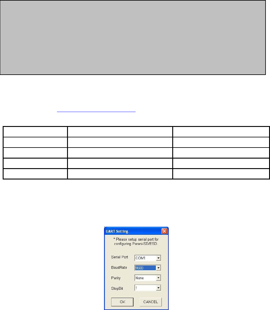
3.7. ParaniWIN
ParaniWIN is a program that runs on Microsoft Windows for the configuration of IW06. Install
ParaniWIN on your computer. Plug a IW06 into the serial port of the computer and turn on the power.
Run ParaniWIN.
Figure 3-1 Serial Port Setting
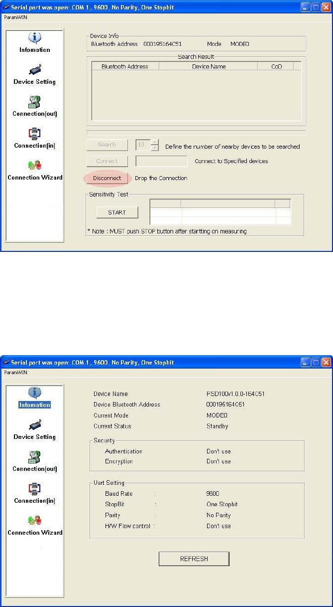
Set each option properly and click [Confirm]. If the settings of the IW06 are different from the
ParaniWin, an error message will pop up. If the IW06 is in the status of connection, warning message
will pop up. Then the current connection can be cancelled by [Disconnect] button on the main window.
CONNECT 000195000001
+++
Please Enter Password
AT+PASS=0000
Remote Configuration Enabled
AT+BTINFO?
000195000001,SD1000v2.0.3-095515,MODE0,CONNECT,0,0,HWFC
15
Figure 3-2 Main Window
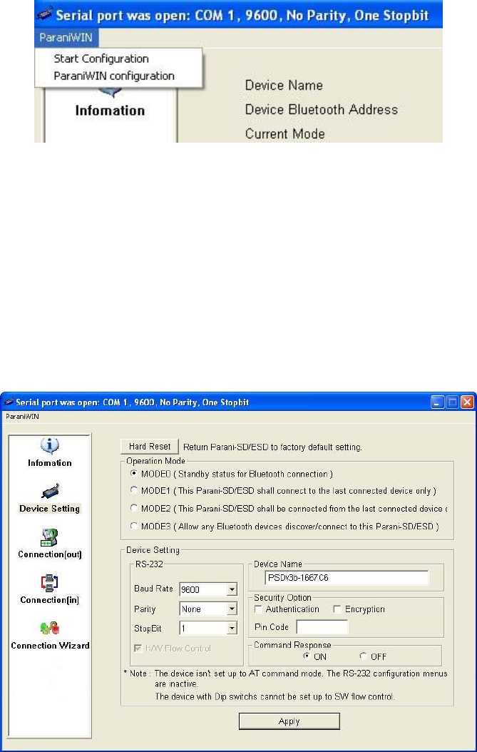
Figure 3-3 Information Window
16
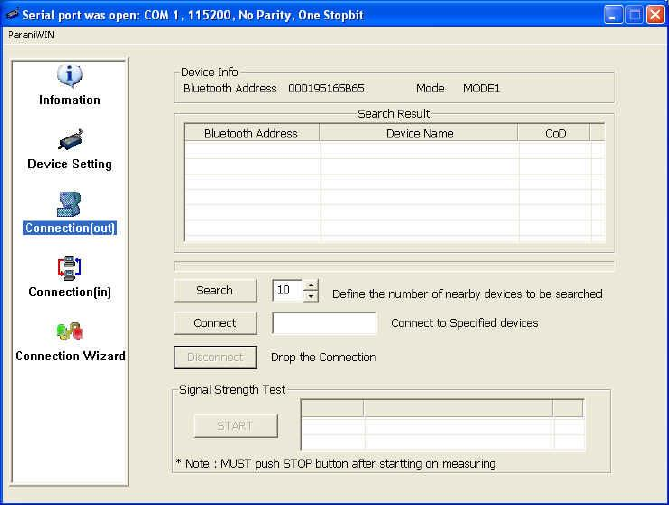
Serial port settings can be changed by <Start Configuration> and <ParaniWIN Configuration> of
ParaniWIN in the menu bar at upper left corner of the window without re-running the ParaniWIN
program.
Figure 3-4 Menu Bar at Upper Left corner of ParaniWIN
When the ParaniWin software is able to access the IW06 properly, the icons in the left side window
come will become available for use.
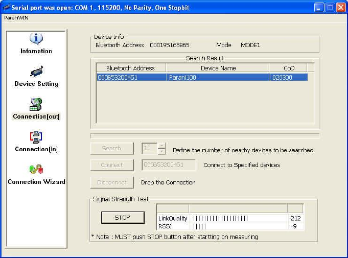
In device configuration window, hardware reset can be executed or operation mode and RS232 can
be configured as well. Security option also can be configured in this window.
Figure 3-5 Device Setting Window
IW06 supports two security options, Authentication and Encryption. If you check the Authentication
option, you must also enter the Pin Code value. If the authentication is activated, the connection, only
between the Master and Slave device that share the same Pin Code, is established. IW06 supports
two security options, Authentication and Encryption. If you enable the Authentication option, you must
17
also enter a Pin Code value. If the authentication is enabled, the connection, between the Master and
Slave device must share the same Pin Code. In case that IW06 connects to another Bluetooth device,
that requires authentication, you must know the other device’s Pin Code. In general, most Bluetooth
devices have a pincode of 1234 or 0000. If you check Encryption option, the IW06 will encrypt packets
and sent to the device. The Encryption options works well in case that only one of the devices
between Master and Slave use the Encryption option.
IW06 has 4 response messages, ‘OK’, ‘ERROR’, ‘CONNECT’, and ‘DISCONNECT’. In some cases,
these responses can affect the host system unexpectedly. To prevent this, user can set the Command
response to ON or OFF.
Click [Apply] button to apply any changes made to the IW06.
Connection(out) icon will show the following window to search and connect other Bluetooth devices.
Figure 3-6 Connection(out) Window
Click [Search] button to search nearby Bluetooth devices. Once several Bluetooth devices has been
found, select one of the devices and click the [Connect] button. The selected Bluetooth device must be
discoverable and connectable. Click [Disconnect] button to cancel the connection.
After the connection has been established, you will be able to test signal strength by pushing the
START button.
18
Figure 3-7 Signal Strength Test
The signal strength test shows LInkQuality and RSSI values. The closer LinkQuality is to 255 and
RSSI is to 0, this means the IW06 has a good connection to the connected Bluetooth device. In
general, the wireless connectivity is at its best within 10 meters. You can push the STOP button at
anytime in order to terminate the signal strength test. The signal strength test will continue until the
STOP button is pushed. If you close the ParaniWIN Window without pushing the STOP button, you
must restart IW06 to terminate the test.
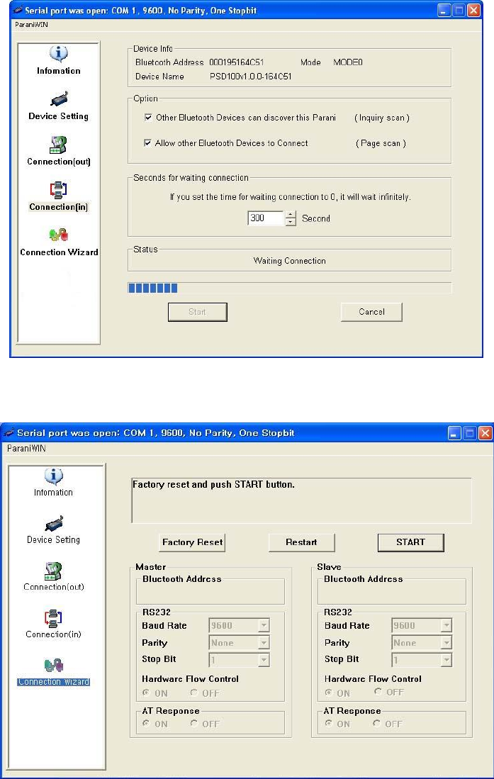
Connection(in) icon will show the following window, which enables the IW06 to wait for a connection
from another Bluetooth device. If the waiting time is set to 0, IW06 will continually wait for connection
until [Cancel] button is clicked.
19
Figure 3-8 Connection(in) Window
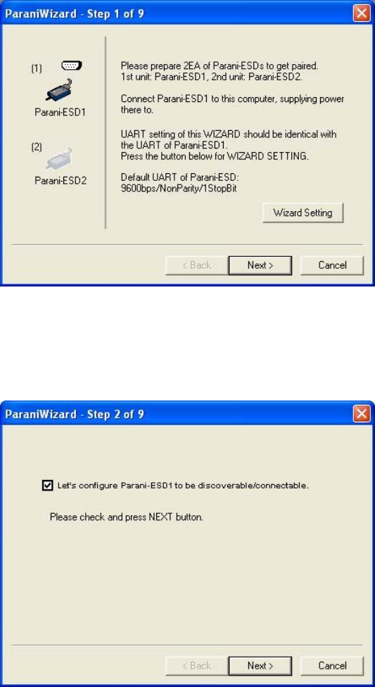
If the Connection Wizard icon is clicked, an easy to use pairing menu will appear:
Figure 3-9 Connection Wizard Window
In this example we will refer to the two IW06s as ESD1 and ESD2 respectively. To use this menu,
please do the following:
Step 1. Connect ESD1 and then push the START button.
Step 2. Disconnect ESD1, connect ESD2 and then push the Next button after setting up Slave
configuration.
Step 3. Disconnect ESD2, once again connect the ESD1 and then push the Finish button. The pairing
20
configuration should be completed. Make sure that each IW06’s connect LED is on. At this point,
when both IW06’s are restarted the connection will be established automatically.
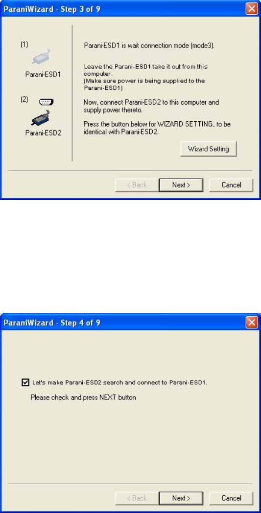
3.8. ParaniWizard
ParaniWizard is a Wizard program that will allow you to configure a pair of IW06’s for an automatic
connection. To make connection with Bluetooth devices other than IW06, use ParaniWIN or AT
commands on a terminal program.
In this example, we will refer to the two IW06’s as ESD1 and ESD2 respectively.
Install and run ParaniWizard.
Figure 3-10 ParaniWizard Step 1
Plug ESD1 into the serial port of the host computer and power on the unit. Click [Wizard Setting]
button to configure the serial port settings of ESD1. These settings must be the same as those of the
host system, to which ESD1 will be used. Click [Next].
Figure 3-11 ParaniWizard Step 2
21
Click [Next] with after selecting the check box, which makes the unit discoverable, in which ESD1 can
be discovered and connected from the other Bluetooth device.
Remove ESD1 from the host computer, remember to leave the ESD1 powered on.
Now, plug ESD2 into the serial port of the host computer and power on the unit.
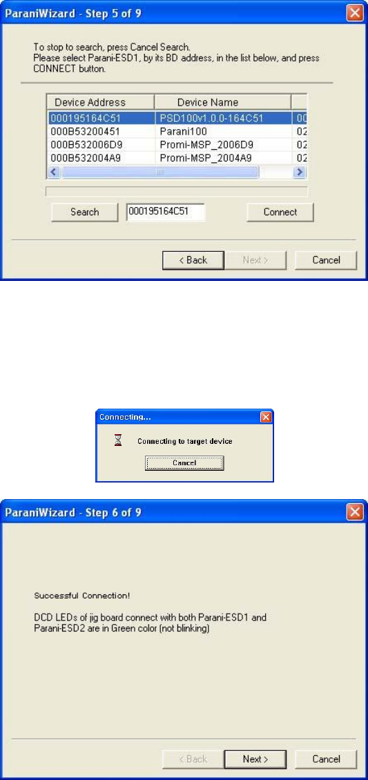
Figure 3-12 ParaniWizard Step 3
Click [Wizard Setting] button to configure the serial settings of ESD2. These settings must be same as
those of the host system, to which ESD2 will be used. Click [Next].
Figure 3-13 ParaniWizard Step 4
22
Click [Next] after selecting check box. ESD2 will then do a search nearby, and search for Bluetooth
devices for 30 seconds. The program will show the Bluetooth devices with Device Address, Device
Name and CoD (Class of Device).
Figure 3-14 ParaniWizard Step 5
Select the ESD1 from the list and click [Connect], then the following message box will be displayed.
Figure 3-15 ParaniWizard Step 6
23
It may take about 5 seconds to complete the connection.
For the automatic connection to take place between ESD1 and ESD2, the proper operation mode of
ESD1 and ESD2 have to be set.
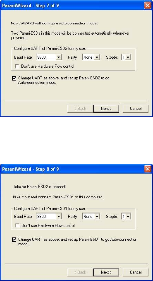
Figure 3-16 ParaniWizard Step 7
Set the operation mode of ESD2 to Mode1.
Figure 3-17 ParaniWizard Step 8
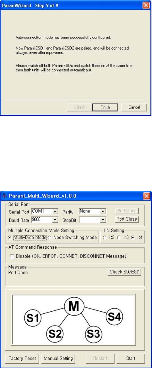
Remove the ESD2 from the host computer and plug ESD1 into the serial port again. Set the operation
mode of ESD1 to Mode2.
24
Figure 3-18 ParaniWizard Step 9
Now the configuration of ESD1 and ESD2 has been completed. Now when the units are turned off and
then turned on again, they will make an automatic connection to each other.
3.9. Parani Multi Wizard
Parani Multi Wizard is the software tool for multiple connection mode configurations of the Parani-SD
and IW06 products.
Figure 3-19 Parani Multi Wizard Window
25
Parani Multi Wizard supports the Wizard mode and the Manual mode. The Wizard mode provide the
user step-by-step instructions for multiple mode configurations. To run the Wizard mode, select
“Multiple connection mode setting” and “1:N setting”, press “Start” button and follow the instructions.
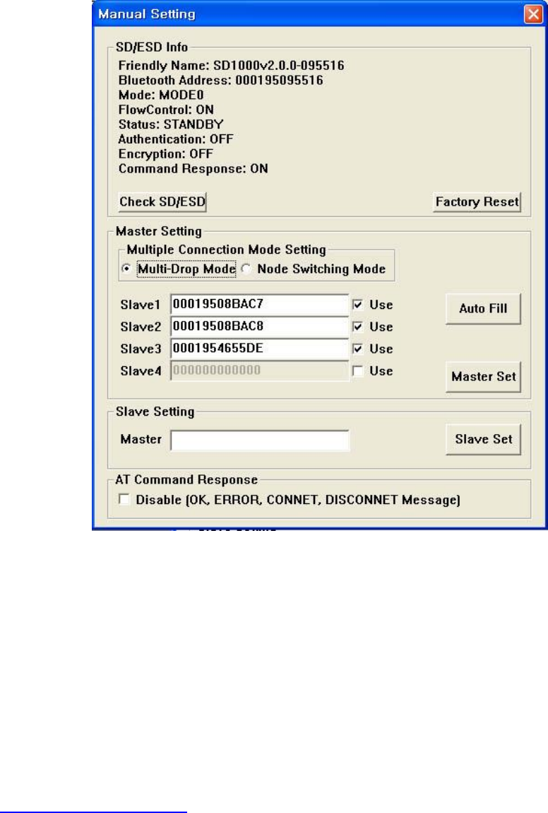
Figure 3-20 Manual Setting Window
In the Manual mode, all settings for the multiple connection mode can be configured in one window. If
a Use field is unchecked or a slave address is entered as 000000000000, it is excluded from the Slave
settings.
The Auto Fill button will load the existing multiple connection mode settings from the Parani-SD/ESD
connected, which can be useful when only some parts of the settings are changed.
If the AT Command Response Disable check box is checked on, the AT command responses such as
OK, ERROR, CONNECT, DISCONNECT are suppressed.
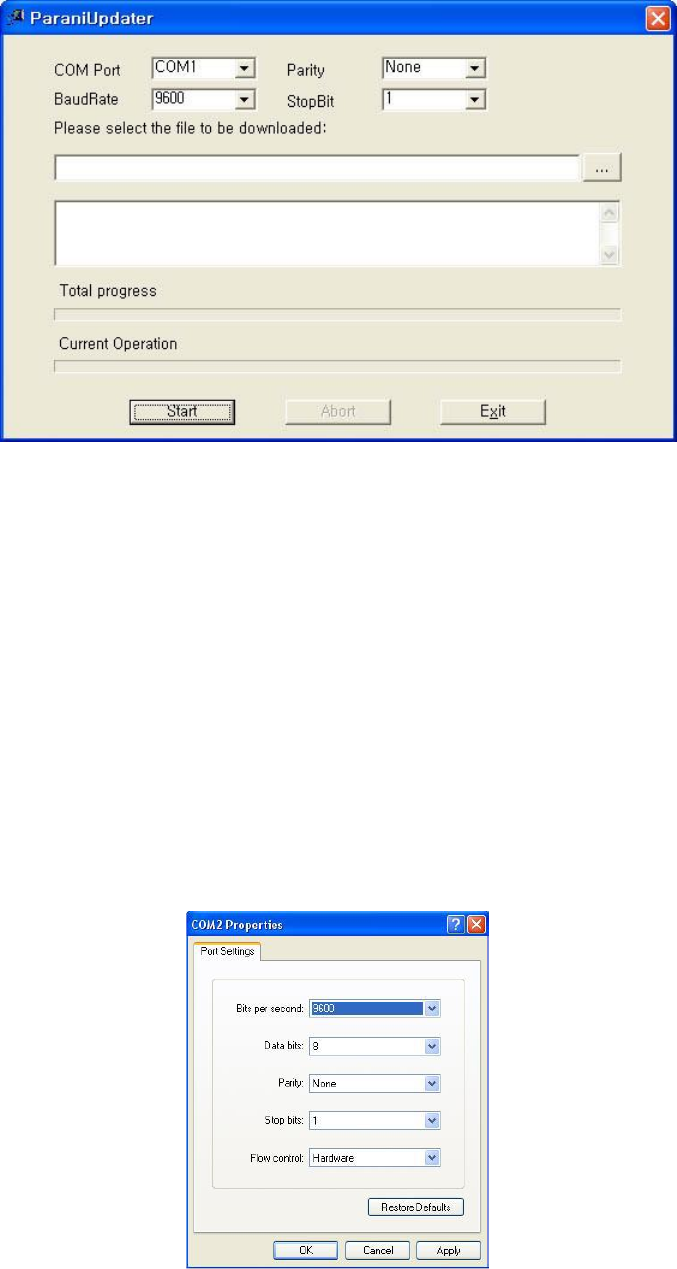
3.10. ParaniUpdater
IW06 supports firmware updates. You can download new firmware images for the IW06 at
http://www.senaindustrial.com. With the ParaniUpdater, you can update the firmware of IW06 by
selecting the firmware image file and pushing Start button.
* Note: DO NOT power off IW06 while the firmware update is progressing, this may damage the IW06.
26
Figure 3-21 ParaniUpdater Window
3.11. Terminal Program
A terminal program is typically an application that will enable a PC to communicate directly with a
modem. If you are using Windows 98SE or higher version of Windows, HyperTerminal program is
included as part of the operating system. IW06 provides some extended AT commands for
configuration of the IW06.
This manual will explain the method using HyperTerminal. If you need to install HyperTerminal, click
start>setting>control panel>add/remove programs. For more precise details on HyperTerminal
installations, please refer to Microsoft Windows Help section.
Attach IW06 to serial port of host computer and power on the unit.
Launch HyperTerminal. It can be found in start menu >programs >accessories >communication
>HyperTerminal. Select the Serial port that IW06 will be connected to.
Input the same settings into Serial port configuration window as IW06 settings.
Select the Serial port setting in the window displayed, please make sure the serial settings in
Hyperterminal are set to the same settings as the IW06’s serial settings.
Figure 3-22 HyperTerminal

27
To view the AT commands that are being typed, you will need to enable the local echo option. Go to
File->Properties->Settings->ASCII setup and select the “Echo typed characters locally” option.
For expanded AT commands, please refer to Appendix A. AT commands.
Example of AT commands:
at
OK
at+btinfo?
000195000144,ESD100V3_v2.0.0-000144,MODE0,STANDBY,0,0,NoFC
OK
at+btinq?
000B5320070E,Promi-MSP_20070E,020300
0009DD500027,LEECOM,1E010C
OK
atd000b5320070e
OK
CONNECT 000B5320070E
28
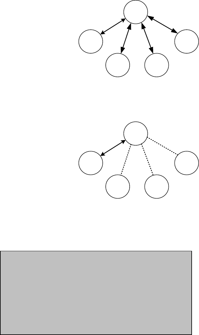
4. Multiple Connection Mode
4.1. Overview
IW06 supports multiple connections up to 4 slave units. There are two types of multiple connection
modes: Multi-Drop Mode and Node Switching Mode.
M
S1 S4
S3S2
Figure 4-1 Multi-Drop Mode
In Multi-Drop Mode a master unit can connect to maximum 4 slave units at the same time and they
transfer data bi-directionally as in Figure 4-1.
M
S1 S4
S3S2
Figure 4-2 Node Switching Mode
In Node Switching Mode, the master unit maintains multiple connections with maximum 4 slave units
but only one connection with one slave unit is active and data is transferred as shown in Figure 4-2.
After connected to slave, master acts command mode. Active slave is selected by AT commands.
On communication after connecting
ATO1 – Communicating with #1 Slave
+++
OK
ATO000195000003 – Communicating with slave of BD 000195000003

29
4.2. Configuration
All the slaves should be in the status of waiting for connection either in Mode 2 or Mode 3 and the
master unit tries to connect to the slave units. The master unit needs to be configured to work in a
multiple connection mode using AT+MULTI,x command, which makes master reboots after execution.
Table 4-1 AT+MULTI,x
AT+MULTI,0
Single Connection Mode
AT+MULTI,1
Multi-Drop Mode
AT+MULTI,2
Node Switching Mode
Table 4-2 Configuration of a Multiple Connection Mode
Manual Connection
Automatic Connection
ATD000195000001
CONNECT000195000001
+++
OK
ATD000195000002
CONNECT000195000002
+++
OK
ATD000195000003
CONNECT000195000003
+++
OK
ATD000195000004
CONNECT000195000004
+++
ATS46=000195000001
OK
ATS54=000195000002
OK
ATS55=000195000003
OK
ATS56=000195000004
OK
AT+MULTI,1 or AT+MULTI,2
OK
AT+BTMODE,1
After rebooted automatically
master tries to connect to
slaves
After input the BD addresses of the slave units into 4 S-registers S46, S54, S55 and S56 and then set
operation mode as MODE1, users can use multiple connection function. If S-registers have available
slaves’ address, AUTO CONNECT message will be displayed following corresponding TASK.
TASK1 OK – AUTO CONNECT
TASK2 OK
TASK3 OK – AUTO CONNECT
TASK4 OK

30
4.3. AT Commands
4.3.1. AT+MULTI,n
Select a multiple connection mode. Refer to Table 4-1 for descriptions.
4.3.2. AT+MLIST?
It shows the current mode, the connection status and the BD addresses of slaves.
4.3.3. ATHx, ATHbdaddr
Using the ATH command, connections with all slaves or only connections with specific slaves can be
disconnected selectively
Table 4-3 ATH
ATH
Disconnect all the slaves.
ATHx (ATH1, ATH2, ATH3, ATH4)
Disconnect the slave which belongs to the TASK x.
ATHbdaddr (ATH000195000001)
Disconnect the slave with specified BD address.
4.3.4. ATOx, ATObdaddr
Using the ATO command, the communication status with the last active slave or a specific slave can
be set to online (only in Node Switching Mode).
Table 4-4 ATO
ATO
Communicate with the slave recently communicated.
ATOx (ATO1, ATO2, ATO3, ATO4)
Communicate with the slave which belongs to the TASK x.
ATObdaddr (ATO000195000001)
Communicate with the slave with specified BDaddress.
at+mlist?
CURRENT MODE: MULTI DROP
TASK1 – 000195000001
TASK2 – 000195000002
TASK3 – DISCONNECT
TASK4 - 000195000004
OK
31
4.4. Notes
When large data exchange occurs in Multi-drop mode without flow-control enabled, the master unit
may experience data loss. It may also experience occasional disconnections and/or system rebooting
especially when bi-directional communication happens. It is strongly recommended to perform
extensive performance test before any real world field applications.
The master unit would try to connect all slave units specified by S-register 46, 54, 55 and 56. If non-
existing or inactive slave addresses are entered in these S-registers, the overall performance will
degrade due to frequent connection trials to non-existing/inactive slaves. It may also force
disconnections for overall performance and outputs disconnect messages repeatedly.
Node-switching mode provides nearly equivalent performance as single connection mode. It is always
recommended to use flow-control for both of Multi-Drop Mode and Node Switching Mode.
32
5. Approval Information
5.1. FCC
Any changes or modifications to the equipment not expressly approved by the party responsible for
compliance could void user’s authority to operate the equipment.
This device complies with part 15 of the FCC Rules. Operation is subject to the following two
conditions:
(1) This device may not cause harmful interference, and
(2) This device must accept any interference received. Including interference that may cause
undesired operation
This device has been tested and found to comply with the limits for a Class B digital device, pursuant
to part 15 of the FCC Rules.
These limits are designed to provide reasonable protection against harmful interference in a
residential installation. This equipment generates, uses and can radiate radio frequency energy and, if
not installed and used in accordance with the instructions, may cause harmful interference to radio
communications. However, there is no guarantee that interference will not occur in a particular
installation. If this equipment does cause harmful interference to radio or television reception, which
can be determined by turning the equipment off and on, the user is encouraged to try to correct the
interference by one or more of the following measures:
- Reorient or relocate the receiving antenna.
- Increase the separation between the equipment and receiver.
- Connect the equipment into an outlet on a circuit different from that to which the receiver is
connected.
This device complies with FCC radiation exposure limits set forth for an uncontrolled environment.
This device should be installed and operated with minimum distance 20cm between the radiating
element of this device and the user. This device must not be co-located or operating in conjunction
with any other antenna or transmitter.
This device is intended only for OEM integrators and following statements shall be included to host
user manual
1) The antenna must be installed such that 20cm is maintained between the antenna and users.
2) This module may not be co-located with any other transmitters or antennas.
As long as 2 conditions above are met, further transmitter test will not be required. However, the OEM
integrator is still responsible for testing their end-product for any
additional compliance requirements with this module installed. In the event that these conditions
cannot be met, then the FCC authorizations are no longer considered valid and the FCC ID cannot be
used on the final product. In these circumstances, the OEM integrator will be responsible for re-
evaluating the end product including this module and obtaining separate FCC authorizations.
The module is labeled with its own FCC ID and IC Certification Number. If the FCC ID and IC
Certification Number are not visible when the module is installed inside another device, then the
outside of the device into which the module is installed must also display a label referring to the
enclosed module. In that case, the final end product must be labeled in a visible area with the
following:
“Contains FCC ID: S7A-IW06
“Contains IC: 8154A-IW06

33
5.2. IC
This device complies with Industry Canada license-exempt RSS standard(s).
Operation is subject to the following two conditions:
(1) this device may not cause interference, and
(2) this device must accept any interference, including interference that may cause undesired
operation of the device.
Le present appareil est conforme aux CNR d'Industrie Canada applicables aux appareils radio
exempts de licence. L'exploitation est autorisee aux deux conditions suivantes :
(1) l'appareil ne doit pas produire de brouillage, et.
(2) l'utilisateur de l'appareil doit accepter tout brouillage radio electrique subi, meme si le brouillage est
susceptible d'en compromettre le fonctionnement.
The antenna must be installed so as to maintain at all times a distance minimum of at least 20 cm
between the radiation source and any individual. This device may not be installed or used in
conjunction with any other antenna or transmitter.
L’antenne doit être installée de façon à maintenir à tout instant une distance minimum de au moins 20
cm entre la source de radiation et toute personne physique. Cet appareil ne peut pas être installé ou
utilisé avec une autre antenne ou émetteur.
This radio transmitter (Model: IW06) has been approved by Industry Canada to operate with the
antenna types listed below with the maximum permissible gain indicated. Antenna types not included
in this list, having a gain greater than the maximum gain indicated for that type, are strictly prohibited
for use with this device.
Cet émetteur radio (modèle: IW 06) a été approuvé par Industrie Canada pour fonctionner avec les
types d'antennes répertoriés ci-dessous avec le gain maximal autorisé indiqué. Les types d'antennes
non inclus dans cette liste, ayant un gain supérieur au gain maximal indiqué pour ce type, sont
strictement interdits pour une utilisation avec cet appareil.
Type
Frequency[MHz]
Max gain[dBi]
Dipole antenna
2402~2480
5.70
Chip antenna
2402~2480
1.00
*In case of dipole antenna, it is maximum gain 5.2dBi including cable loss.
É tiquetage du produit final (IC)
Le module est étiqueté avec sa propre identification FCC et son propre numéro de certification IC. Si
l’identification FCC et le numéro de certification IC ne sont pas visibles lorsque
le module est installé à l’intérieur d’un autre dispositif, la partie externe du dispositif dans lequel
le module est installé devra également présenter une étiquette faisant référence au module inclus.
Dans ce cas, le produit final devra être étiqueté sur une zone visible avec les informations suivantes :
« Contient module émetteur identification FCC ID : S7A-IW06
« Contient module émetteur IC : 8154A-IW06
5.3. CE
Hereby, SENA TECHNOLOGIES.Inc Declares that this IW07 is in compliance with the essential
requirements and other relevant provisions of directive 1999/5/EC.

34
6. RF Information
6.1. Radio Frequency Range
2.402~2.480GHz
6.2. Number of Frequency Channel
79 channels
6.3. Transmission Method
FHSS(Frequency Hopping Spread Spectrum)
6.4. Modulation Method
1Mbps: GFSK(Gaussian Frequency Shift Keying)
2Mbps: π/4 DQPSK(pi/4 rotated Differential Quaternary Phase Shift Keying)
3Mbps: 8DPSK(8 phase Differential Phase Shift Keying)
6.5. Receiving Sensitivity
Products
Receiving Sensitivity
IW06
-90dBm
6.6. Power Supply
Products
Power Supply
IW06
DC3.3V
35
Appendix A: Connections
A.1. Pin Assignment
A.1.1. IW06
7 8 9 10 11 12
2 3 4 5 6
1
GND
GNDPairing
VDDRTSTXD RXD CTS
DTRDCD DSR RST
Figure A-1 Pin Assignment of IW06
Table A-1. Pin Assignment of IW06
Pin #
Signal
Direction
Description
Signal Level
1
GND
-
Power Ground
Ground
2
TxD
Output
UART Data Output
TTL
3
RxD
Input
UART Data Input
TTL
4
RTS
Output
UART Ready to Send
TTL
5
CTS
Input
UART Clear to Send
TTL
6
VDD
Input
DC Input (3.0~3.3V)
Power
7
Pairing
Input
Pairing Input (Active Low)
TTL
8
DCD
Output
Bluetooth Connect Detect (Active Low)
TTL
9
DSR
Input
Data Set Ready
TTL
10
DTR
Output
Data Terminal Ready
TTL
11
RST
Input
Reset (Active Low)
TTL
12
GND
-
Power Ground
Ground
A.1.2. DCD Signal (Status: Bluetooth Connect Detect)
Status of Bluetooth connection will be delivered to Host PC via DCD line. When Bluetooth connection
is made, DCD signal will be to low.

36
A.1.3. Factory Reset Signal
Factory reset signal will be used for setting the IW06 to factory defaults. Factory reset signal should be
on 0V status for at least 1 second for the reset to occur.
A.1.4. Pairing (BT_MODE) Signal (Single Connection Mode Only)
IW06 provides a pairing signal input for instant configuration and automatic connection to two IW06s.
In this example, we will name the two IW06s as ESD1 and ESD2. In pairing mode.
Step 1. Turn on ESD1 and ESD2 and do factory default both of them by using RST signal.
Step 2. Set the pairing signal of ESD1 to a low state and hold the signal for 2 seconds.
Step 3. Set the pairing signal of ESD2 to a low state and hold the signal for 2 seconds.
Set the pairing signal of ESD2 to high state and hold the signal for 2 seconds. Now Set the pairing
signal of ESD2 to low state and hold it for 2 seconds
Step 4. Wait for ESD1 & ESD2 to connect to each other. It may take about 10 seconds to make a
connection. If there are many Bluetooth devices nearby, the connection time may increase.
Step 5. At this point your pair of IW06 is configured to make automatic connection to each other.
You can now use this pair of IW06’s like virtual serial cable.
* Note : During the pairing process, by way of the pairing signal, the Command Response will be
deactivated. Thus, the IW06 will not send the response messages such as OK, Connect and
Disconnect.
Table A-2 Pairing Process by Pairing Signal
ESD1
Status
Pairing Signal
ESD2
Status
Pairing Signal
1. Reset
Mode0
HIGH
1. Reset
Mode0
HIGH
2. Drop pairing
signal
Mode3
LOW
2. Drop pairing signal
Mode3
LOW
3.Restore
pairing signal
Mode3
HIGH
3.Restore
pairing signal
Mode3
HIGH
4. Drop pairing signal
Mode1
LOW
5.Restore
pairing signal
Mode1
HIGH
6. Connected
Slave
HIGH
6. Connected
Master
HIGH
Using pairing button, users can make a pairing connection between a IW06 unit and other Bluetooth
devices.
Step 1. Turn on ESD1 and do factory default by using RST signal.
Step 2. Set the pairing signal of ESD1 to a low state and hold the signal for 2 seconds.
Step 3. Users can discover and connect to ESD1 by using the software or user interface of other
Bluetooth device that they want to connect from.
Step 4. Wait for ESD1 & other Bluetooth device to connect to each other. It may take about 10
seconds to make a connection. If there are many Bluetooth devices nearby, the connection time
may increase.
Step 5. Now ESD1 is waiting for a connection from the last connected Bluetooth device. The last
connected Bluetooth device can connect to ESD1.
37
Table A-3 Pairing Process with other Bluetooth device by Pairing Signal
ESD1
Status
Pairing Signal
Other Bluetooth Deivce
Status
1. Reset
Mode0
HIGH
2. Drop pairing signal
Mode3
LOW
3. Inquiry and connect to
ESD1
4. Connected
Slave
HIGH
4. Connected
Master
*Caution : When you are designing a new hardware, you must maintain the pull up status by hardware
for pairing signals. If pairing signals are floating by hardware, unexpected errors may occur.
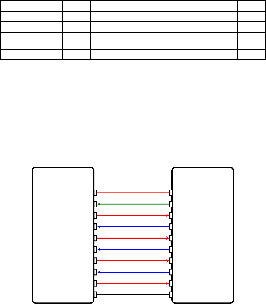
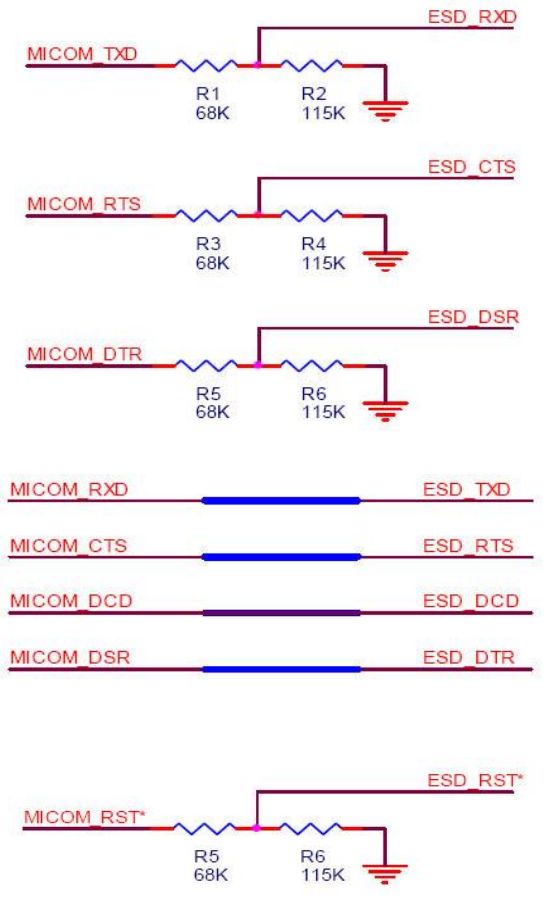
A.2. Connection Diagram
A.2.1. IW06
A.2.1.1. When TTL level of MICOM is 3.3V
MICOM
MICRO-VDD
MICOM-RXD
MICOM-CTS
MICOM-RTS
MICOM-RST
MICOM-DTR
MICOM-DSR
TXD
RXD
CTS
RTS
RST
DTR
DSR
MICOM-TXD
MICOM-GND
VDD
GND
MICOM-DCD DCD
DC 3.3V
PARANI-ESD
38
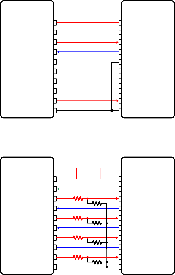
A.2.1.2. When TTL level of MICOM is 3.3V and Hardware Flow Control is not used
MICOM
MICRO-VDD
MICOM-RXD
MICOM-RST
TXD
RXD
CTS
RTS
RST
DTR
DSR
MICOM-TXD
MICOM-GND
VDD
GND
DCD
DC 3.3V
PARANI-ESD
A.2.1.3. When TTL level of MICOM is 5V
MICOM
MICRO-VDD
MICOM-RXD
MICOM-CTS
MICOM-RTS
MICOM-RST
MICOM-DTR
MICOM-DSR
TXD
RXD
CTS
RTS
RST
DTR
DSR
MICOM-TXD
MICOM-GND
VDD
GND
MICOM-DCD DCD
DC 3.3V
68K115K
68K115K
68K115K
68K115K
DC 5V
PARANI-ESD
39

40
Appendix B: AT Commands
B.1. Terminology
B.1.1. AT Command
AT command set is a HTin fact standardTH HTlanguageTH for controlling HTmodemsTH. The AT command set was
developed by HTHayesTH and is recognized by virtually all HTpersonal computerTH modems. IW06 provides the
extended AT command set to control and configure the serial parameters and Bluetooth connection.
B.1.2. AT Response
IW06 replies to AT commands with 4 kinds of message, ‘OK’, ‘ERROR’, ‘CONNECT’ and
‘DISCONNECT’.
B.1.3. Operation Mode
Mode
Description
Mode0
Waiting for AT commands
Mode1
Attempting to connect to the last connected Bluetooth device
Mode2
Waiting for a connection from the last connected Bluetooth device
Mode3
Waiting for the connection from another Bluetooth device
B.1.4. Operation Status
Status
Description
Standby
Waiting for AT commands
Pending
Executing tasks
Connect
Transmitting data
B.1.5. Security
Security
Description
Authentication
Pin Code (or Pass key)
Encryption
Data encryption
B.1.6. Symbols
The symbols are used for the description of command syntax as follows:

41
Symbols
Meaning
ASCII Code
Carriage return
0x0D
Line feed
0x0A
Carriage return + Line feed
112233445566
Bluetooth device address
N or m
One digit decimal number
To
Timeout in seconds
B.2. Command Category
Command Category
Index
AT Commands
RESET
1
2
ATZ
AT&F
SERIAL PORT
3
4
AT
AT+UARTCONFIG,b,p,s,h
BLUETOOTH
Information
5
6
7
8
9
10
AT+BTINFO?
AT+BTINQ?
AT+BTLAST?
AT+BTVER?
AT+BTRSSI,n
AT+MLIST?
Mode
11
12
AT+BTMODE,n
AT+MULTI,n
Status
13
14
15
16
17
18
19
+++
AT+SETESC,nn
ATO
AT+BTCANCEL
AT+BTSCAN
AT+BTSCAN,n,to
AT+BTSCAN112233445566,to
Connection
20
21
22
23
24
ATD
ATD112233445566
ATA
ATA112233445566
ATH
Security
25
26
27
28
29
AT+BTKEY=$string
AT+BTSD?
AT+BTCSD
AT+BTFP,n
AT+BTSEC,a,e
Miscellaneous
30
31
AT+BTNAME=$string
AT+BTLPM,n
REMOTE CONFIGURATION
32
33
AT+PASS=”nnnnnnnn”
AT+CHPASS=”nnnnnnnn”
S-REGISTER
34
35
36
AT&V
ATSnn?
ATSnn=mm

42
B.3. Command Description
B.3.1. ATZ
Response
OK
Purpose
Software Reset
Description
This has the same effects as Powercycling the unit.
This command disconnects any connected Bluetooth device, and stops ongoing tasks.
After rebooting, the status will be decided by the preset operation mode.
Some AT commands require the ATZ command be run so that the commands can take
effect.
B.3.2. AT&F
Response
OK
Purpose
Hardware reset
Description
This has the same effect as initialization by pressing the factory reset button.
All parameters are initialized to factory defaults
B.3.3. AT
Response
OK
Purpose
Check the connection status with host equipment
Description
Check if the connection to host equipment is operating normally. The serial parameters of
IW06 must be same as those of host equipment. If not, the IW06 will not respond or
‘ERROR’ message will appear or an abnormal sequence of strings will appear.
B.3.4. AT+UARTCONFIG,Baudrate,Parity,Stopbit,Hwfc
Response
OK
Purpose
Set Serial parameters
Parameters
Baudrate=1200/2400/4800/9600/14400/19200/38400/57600/115200/230400/460800/921600
(Default=9600)
Parity=N/E/O (Default=N)
Stopbit=1/2 (Default=1)
Hwfc(Hardware Flow Control)=0/1 (Default=1)
Description
The Serial parameters can be set or changed. The factory default is 9600, N, 1, 1.
To take effect the ATZ command must be used or Powercycle the unit.
Example
AT+UARTCONFIG,115200,N,1,1
B.3.5. AT+BTINFO?
Response
112233445566,DeviceName,Mode,Status,Auth,Encryp,FlowControl
OK
Purpose
Display Bluetooth settings
Description
The current Bluetooth settings are displayed including BD address, Device name,
Operation mode, Operation status, Authentication, Data Encryption, and Hardware Flow

43
Control. The initial value of Device name is ‘ESD100V3_v2.0.0-445566’. ESD stands for
IW06, v2.0.0 for the version of firmware, and 445566 for the last 6 digits of BD address.
Mode=MODE0/MODE1/MODE2/MODE3
Status=STANDBY/PENDING/CONNECT
Auth=0/1 (Authentication is not activated when 0)
Encrypt=0/1 (Encryption is not activated when 0)
FlowControl=HWFC/NoFC
Example
000B530011FF,SENA,MODE0,PENDING,1,1,HWFC
B.3.6. AT+BTINQ?
Response
112233445566,FriendlyName,CoD
112233445566,FriendlyName,CoD
112233445566,FriendlyName,CoD
OK
Purpose
Search Bluetooth devices nearby
Description
The Bluetooth devices in Inquiry scan mode nearby are displayed with their BD addresses,
Device names, and Class of device.
Maximum 15 devices are scanned for 30 seconds. (Default 15 value in S-register 24)
B.3.7. AT+BTLAST?
Response
112233445566
Purpose
Display the BD address of the last connected device
Description
The Bluetooth device last connected to this IW06 is displayed with its BD address.
B.3.8. AT+BTVER?
Response
ESD100V3_v2.0.0
OK
Purpose
Display device firmware version
Description
Display device firmware version
B.3.9. AT+BTRSSI,n(Single Connection Mode Only)
Response
OK
0,255,0,0 (repeatedly)
Purpose
Test signal strength
Parameters
n=0: Stop signal strength test
n=1: Start signal strength test
Description
When Bluetooth connection is established, you can use this command in Standby status.
The signal strength will be displayed repeatedly in order of Status, LinkQuality, Status,
RSSI. If the LinkQuality is close to 255 and RSSI is close to 0, the signal strength is in good
standing.
Example
+++
AT+BTRSSI,1
OK
0,255,0,0

44
B.3.10. AT+MLIST?
Response
CURRENT MODE:SINGLE CONNECTION MODE
OK
Purpose
Display the current multiple connection mode and connected slave’s Bluetooth addresses.
Description
Display current mode(SINGLE CONNECTION MODE , MULTI-DROP MODE, NODE
SWITCHING MODE) and connected slave Bluetooth address.
Example
AT+MLIST?
CURRENT MODE: MULTI-DROP MODE
TASK1 – 000195000001
TASK2 – DISCONNECT
TASK3 – DISCONNECT
TASK4 – 000195000004
B.3.11. AT+BTMODE,n
Response
OK
Purpose
Set operation mode
Parameters
n=0: MODE0 (Default)
n=1: MODE1
n=2: MODE2
n=3: MODE3
Description
When the operation status is ‘Pending’ currently, change the status to ‘Standby’ with
AT+BTCANCEL prior to this command.
To take effect the ATZ must be executed or Powercycle the unit
Example
AT+BTMODE,2
OK
ATZ
B.3.12. AT+MULTI,n
Response
(n = 0)
OK
(n = 1 or n = 2)
TASK1 OK
TASK2 OK
TASK3 OK
TASK4 OK
Purpose
Set multiple connection mode
Parameters
n=0: Single Connection Mode (Default)
n=1: Multi-Drop Mode
n=2: Node Switching Mode
Description
Set single connection mode, multi-drop mode or node switching mode.
B.3.13. +++
Response
OK
Purpose
Convert the operation status of ‘Connect’ to ‘Standby’
Description
In ‘Connect’ status, data from host is transmitted to the other side Bluetooth device, and
any AT command is not accepted but this command, which is not echoed on the screen.
When IW06 encounters a character ‘+’ from host, it stops the data transmission and waits

45
for next 2 characters. If the next 2 characters aren’t both ‘+’, it restart to transmit data
including the first ‘+’ as well. If not, it converts the operation status to ‘Standby’.
If the data from host includes ‘+++’, it will convert the operation status to ‘Standby’. Notice
that IW06 holds data transmission when it encounters ‘+’, until receiving next character.
‘+’ is an escape sequence character by default, which is changeable by AT+SETESC.
* Caution : In low power mode, you cannot change online status to command waiting status
by using the ‘+++’ string. Entering the ‘+++’ string during low power mode and online status
may entail unexpected errors.
B.3.14. AT+SETESC,nn
Response
OK
Purpose
Change the escape sequence character
Description
Escape sequence character set to ‘+’ by default is changeable.
The parameter nn must be a printable character.
Example
AT+SETESC,42
B.3.15. ATO (ATOx, ATObdaddr)
Response
None
Purpose
Convert the operation status of ‘Standby’ to ‘Connect’
Description
You can convert the operation status of ‘Standby’ to ‘Connect’ ready to transmit data. In
Node Switching mode, a specific slave can be specified to become an active connection by
specifying the connection number or the Bluetooth address.
Example
ATO
ATO3
ATO000195000001
B.3.16. AT+BTCANCEL
Response
OK
Purpose
Terminate the current executing task
Description
This terminates a current executing task, such as Inquiry scan and Page scan, then
converts the operation status to ‘Standby’
B.3.17. AT+BTSCAN
Response
OK
CONNECT 112233445566
Purpose
Wait for inquiry and connection from other Bluetooth devices
Description
This allows the inquiry and connection from the other Bluetooth devices. The operation
status will be in ‘Pending’ after this command. When connection is made and released, the
operation status is back to ‘Pending’. To convert the operation status to ‘Standby’
AT+BTCANCEL must be used.
This has the same effect as AT+BTSCAN,3,0.
When connection is made with other Bluetooth device, response will be ‘CONNECT’ with
its BD address.
B.3.18. AT+BTSCAN,n,to

46
Response
OK
CONNECT 112233445566
or
OK
ERROR
Purpose
Wait for inquiry and connection from other Bluetooth devices for a given duration
Parameters
n=1: Allows Inquiry scan
n=2: Allows Page scan
n=3: Allows both of Inquiry scan and Page scan
to= Time duration in seconds
Description
For the given to, IW06 is waiting for the inquiry and connection from other Bluetooth
devices. If the parameter of to is 0, it will wait forever.
When connection is made with other Bluetooth device, response will be ‘CONNECT’ with
its BD address. If there is no connection made within this time duration, response is
‘ERROR’ and the operation status becomes to ‘Standby’.
Example
AT+BTSCAN,2,30
B.3.19. AT+BTSCAN112233445566,to
Response
OK
CONNECT 112233445566
or
OK
ERROR
Purpose
Wait for connection by the Bluetooth device with given BD address
Parameters
112233445566=BD address
to= time duration in seconds
Description
IW06 will wait to be connected to by the Bluetooth device with the given BD address. If the
parameter of to is 0, it will wait forever.
When connection is made with the Bluetooth device, response will be ‘CONNECT’ with its
BD address. If there is no connection made within this time duration, response is ‘ERROR’
and the operation status becomes to ‘Standby’.
Example
AT+BTSCAN000B530011FF,30
B.3.20. ATD
Response
OK
CONNECT 112233445566
or
OK
ERROR
Purpose
Connect to the last connected Bluetooth device
Description
IW06 saves the BD address of the Bluetooth device most recently connected to.
If it fails to make a connection, response will display an ‘ERROR’.
B.3.21. ATD112233445566
Response
OK
CONNECT 112233445566
or
OK
ERROR

47
Purpose
Connect to a specific Bluetooth device with a given BD address
Parameters
112233445566=BD address
Description
IW06 attempts to connect to the Bluetooth device with the given BD address. To make
successful connection, the Bluetooth device must be in Page scan mode. This attempt
continues for 5 minutes.
If it fails to make connection, response is ‘ERROR’.
Example
ATD000B530011FF
B.3.22. ATA
Response
OK
Start ACL Open
ACL Connect Success
Purpose
ACL connect to the last connected Bluetooth device
Description
If it make connection, response will display an ‘ACL Connect Success’. Must have reboot
for new ACL connection.
B.3.23. ATA112233445566
Response
OK
Start ACL Open
ACL Connect Success
Purpose
ACL connect to a specific Bluetooth device with a given BD address
Parameters
112233445566 = BD address
Description
IW06 attempts to ACL connect to the Bluetooth device with the given BD address. To make
successful ACL connection, the Bluetooth device must be in Page scan mode. If it make
connection, response will display an ‘ACL Connect Success’. Must have reboot for new
ACL connection.
Example
ATA0001950011FF
B.3.24. ATH (ATHx, ATHbdaddr)
Response
OK
DISCONNECT
Purpose
Release the current connection
Description
The current Bluetooth connection will be disconnected. It takes about Supervision
Timeout(S37) to detect an abnormal disconnection such as power off and moving out of
service range. In multiple connection modes, a specific connection can be specified to be
disconnected by specifying the connection number or the Bluetooth address.
The response message of ‘DISCONNECT’ may be displayed on disconnection depending
on the disconnection condition. You can make it not displayed using S10 register.
Example
ATH
ATH3
ATH000195000001
B.3.25. AT+BTKEY=$string

48
Response
OK
Purpose
Change pin code
Parameters
$string= New pin code (Default=”1234”)
Description
Pin code is a string, which allows up to 16 alpha-numeric characters. Based on this pin
code, IW06 generates a link key which is used in actual authentication process
Example
AT+BTKEY=”apple”
B.3.26. AT+BTSD?
Response
112233445566
OK
Purpose
Display a list of Bluetooth devices sharing the same pin code
Description
Once a connection is made with a pin code, IW06 saves the Bluetooth device with its link
key, generated by the pin code. The connection to a device listed in IW06 can be made
automatically without the authentication process. The maximum number kept on the list is
7.
B.3.27. AT+BTCSD
Response
OK
Purpose
Clear the list of Bluetooth devices sharing the same pin code
Description
This clears the list of Bluetooth devices linked with the same key in flash memory. To take
effect the ATZ command must be used or Powercycle the unit.
B.3.28. AT+BTFP,n
Response
OK
Purpose
Set generation of link key every time of connection
Parameters
n=0: Inactivate (Default)
n=1: Activate
Description
If n is set to 1, IW06 asks for the pin code every time a connection is made. This can be
used to increase security.
B.3.29. AT+BTSEC,Authentication,Encryption
Response
OK
Purpose
Set authentication and data encryption
Parameters
Authentication=0: Inactivate (Default)
Authentication=1: Activate
Encryption=0: Inactivate (Default)
Encryption=1: Activate
Description
If the authentication is activated, the pin code must be set by AT+BTKEY command. Data
encryption cannot be used when authentication is not enabled, i.e. Authentication=0 and
Encryption=1 will not work properly.

49
B.3.30. AT+BTNAME=$string
Response
OK
Purpose
Change device name
Parameters
$string= New device name (Default=”ESDV2_v2.0.0-445566”)
Description
IW06 can have a user friendly name for easy identification. The name allows up to 30
alpha-numeric characters.
Example
AT+BTNAME=”My-IW06”
B.3.31. AT+BTLPM,n
Response
OK
Purpose
Set low power mode
Parameters
n=0: Inactivate (Default)
n=1: Activate
Description
During no data transmission, IW06 can be in low power mode to save the power. It takes a
few seconds to wake the IW06 out of low power mode.
B.3.32. AT+PASS=$string
Response
Remote Configuration Enabled
Purpose
Input password in remote configuration mode.
Parameters
$string= Password (Default=”0000”)
Description
Input password for authentication in remote configuration mode.
Example
AT+PASS=1234
B.3.33. AT+CHPASS=$string
Response
OK
Purpose
Change password used in remote configuration mode.
Parameters
$string= New password
Description
Change password used in remote configuration mode. Password length is up to 8.
Example
AT+CHPASS=12345678
B.3.34. AT&V
Response
S0:m0;S1:m1; …Sn:mn
OK
Purpose
Display all the S-registers
Description
All parameters are stored at S-register in flash memory. These values are sustained until
hardware reset.
B.3.35. ATSnn?

50
Response
value
OK
Purpose
Display a given S-register
Parameters
nn= Address of S-register
Description
A specific S-register will be displayed.
B.3.36. ATSnn=mm
Response
OK
Purpose
Change S-register value
Parameters
nn= Address of S-register
mm= New value of S-register
Description
Some S-registers are optimized for the overall performance and protected and cannot be
changed. When users try to change these S-registers, response is ‘ERROR’.
For details of S-register, refer Appendix. B.
Example
ATS10=0
B.4. Command Validity
AT Command
Operation Status
Standby
Pending
Connect
AT
○
○
ATZ
○
○
AT&F
○
○
AT+BINQ?
◎
ATD112233445566
◎
ATD
◎
ATA112233445566
◎
ATA
◎
AT+BTSCAN
◎
AT+BTSCAN,n,to
◎
AT+BTSCAN112233445566,to
◎
AT+BTCANCEL
○
+++
○
AT+SETESC
◎
ATO
●
ATH
●
AT+BTSEC,Auth,Encr
◎
AT+BTLAST?
○
○

51
AT+BTMODEn
◎
AT+BTNAME=”Name”
◎
AT+BTKEY=”nnnn”
◎
AT+BTINFO?
○
AT+BTLPM,n
◎
AT+BTSD?
○
○
AT+BTCSD
◎
AT+BTFP,n
◎
AT+UARTCONFIG,b,p,s,h
◎
AT+BTVER?
○
○
AT+BTRSSI,n
●
AT+PASS=”nnnnnnnn”
○
○
AT+CHPASS=”nnnnnnnn”
○
○
◎ Valid only when IW06 is not connected to other Bluetooth device.
● Valid only when IW06 is connected to other Bluetooth device.
52
Appendix C: S-Register
S-registers contain 52 parameters for the IW06. These are stored in flash memory and the values will
be saved unless hardware reset is executed. The value of S-register can be accessed and changed
with ATS command. Some S-registers not shown below are set to maximize the performance of IW06.
Thus it is not recommended to change these S-registers.
Change the value of S-register only in Standby status. Turn IW06 off and on.
C.1. S1: Force to Reconnect (default 1)
S1=0, IW06 in Mode1 does not try to reconnect when disconnected.
S1=1, IW06 in Mode1 keeps trying to reconnect when disconnected.
C.2. S3: Stream UART Policy (default 0)
S3=0, the priority of UART streaming is throughput.
S3=1, the priority is latency, which minimizes the delay of data transmission. This is useful in case of
transmitting very small data quickly.
When this value is 1, in order to minimize latency, IW06 sends the received data immediately. When
this value is 0, the IW06 maximizes throughput, the IW06 stores received data for a short time and
sends a large data packet. If the packet length is less than 100 bytes, having latency being the priority
is recommended. If the packet length is more than 100 bytes, having throughput as the priority is
recommended. Also, if you want to use high baud rate, throughput priority will be more effective. Just
for reference, the buffer length for receiving data is 2 Kbytes.
C.3. S4: Enable Remote Name Query (default 1)
S4=0, IW06 will query only the BD address. This speeds up the inquiry process.
S4=1, IW06 will query the BD address, device name and class of device.
When this value is 1, IW06 finds not only BD address but also friendly name. When this value is 0,
IW06 finds only BD address. When set to 0 this will make queries much faster. When using the pairing
button, finding friendly name will be omitted automatically.
C.4. S6: Enable Low Power Mode (default 0)
S6=0, deactivate Low Power Mode.
S6=1, activate Low Power Mode.
This value decides whether IW06 works in Low Power Mode or not. When this value is 0, IW06 works
only in active power mode. When this value is 1, IW06 will be in low power mode to save the power.
Therefore, it takes a few seconds to wake the IW06 out of low power mode.
C.5. S10: Enable Response Message (default 1)
S10=0, IW06 does not send response messages to the host system.
S10=1, IW06 sends response messages to host system.
This value decides whether IW06 sends response messages such as OK, ERROR, CONNECT,
DISCONNECT or not. When this value is 0, IW06 will not send any response messages. If the
response messages conflicts with your host programs or devices that is connected to IW06, change
this value to 0.
C.6. S11: Enable Escape (default 1)
S11=0, IW06 does not allow escape sequence characters. The operation status of Connect cannot be
changed to Standby. Since the IW06 skips the process of detecting escape sequence characters,
more efficient data transmission can be had.

53
S11=1, IW06 allows for the escape sequence character. Whenever it is needed, the Connect status
can be changed to Standby.
C.7. S12: Clear Data Buffer When Disconnected (default 0)
S12=0, IW06 does not clear the data buffer received from host system when disconnected.
S12=1, IW06 clears the data buffer when disconnected.
C.8. S13: Enable DCD Signal (default 1)
S13=0, DCD signal off
S13=1, DCD signal on
C.9. S14: Enable DTR Transfer (default 1)
S14=0, DTR/DSR signal is transferred in a loop-back fashion..
S14=1, DTR signal is transferred to DSR of remote device.
C.10. S15: Enable Disconnect by DTR (default 0)
S15=0, DTR signal cannot release the connection.
S15=1, The Bluetooth connection can be released when DTR signal is off.
This value decides whether Bluetooth connection is released when DTR signal drops or not. If this
value is 1, you can use DTR signal in order to disconnect Bluetooth connection.
C.11. S22: Faster Connection (default 3)
S22=0, none
S22=1, page scan
S22=2, inquiry scan
S22=3, page/inquiry scan
Connecting time is average 1.5sec faster than normal mode.
C.12. S23: Intercharacter Timeout Setting (default 0)
S23=0 : Not used
S23=1 : 1 x S26
S23=2 : 10 x S26
S23=3 : 100 x S26
C.13. S24: Maximum Number of Inquiry Result (default 15)
The maximum number of inquiry list can be controlled. If value is 0, maximum number is limitless.
C.14. S26: Intercharacter Timeout (default 0)
This value describes time interval between characters used to separate the data from serial port. If
there is no more data coming from serial port in this value, data is sent to client.
S23=1 x S26=50 : Timeout-> 50msec
S23=2 x S26=50 : Timeout-> 500msec
S23=3 x S26=3 : Timeout-> 300msec
Inter Character Time Out
* Optimal Value(S23 x S26)

54
50ms
180
100ms
235
200ms
340
* When 10 bytes data are sent every intercharacter timeout, they are sent separately by 10 bytes at
the optimal value. If the intercharater timeout is set below the optimal value, the data will be put
together and sent by 20, 30, 40 bytes or more.
C.15. S28: Escape Sequence Character (default 43)
The decimal number of the ASCII code of escape sequence character can be controlled. The initial
value is 43, the ASCII code of ‘+’.
C.16. S31: Page Timeout (default 20)
This is the timeout in seconds to attempt connection with the ATD command. After this timeout expires,
the IW06 will restart automatically. If this value is 0, IW06 will attempt to connect without restarting. . It
must set at 5 second units.
C.17. S33: Inquiry Timeout (default 30)
This is the timeout in seconds to execute inquiry scan.
C.18. S37: Supervision Timeout (default 5)
This is the timeout to presume disconnection, which is set to 5 seconds initially. The smaller the value
becomes, the more quickly Parani-SD can detect an abnormal disconnection. But when the
communication is suspended, it may be regarded as disconnection. This value should be greater than
the Slave Disconnect Timeout(S57). (Slave unit depends on the value of master unit.)
C.19. S43: COD (default 001F00)
This value describes the sort of the bluetooth device and is editable.
C.20. S44: COD Filter (default 0)
This value is used to filter the sort of the bluetooth devices on inquiring. All the bluetooth devices are
inquired in case of 0. In case of 3E0100, bluetooth devices with COD 3E0100 are inquired.
C.21. S45: Inquiry Access Code (default 0x9E8B33)
Inquiry access code is used during inquiry state. The reserved IAC addresses are 0x9E8B00 ~
0x9E8B3F. The general inquiry IAC is 0x9E8B33.
IW06 is able to find the Bluetooth devices that are configured as the same IAC.
C.22. S46: BD Address of Last Connected Device
This saves the BD address of the Bluetooth device connected most recently in single connection
mode. This saves the Task1 BD address of the Bluetooth device connected most recently in a multiple
connection mode.

55
C.23. S48: Low Power Max Interval (default 5000)
This is the max interval value to use low power mode, which is set to 5000 initially. (5000 x 625μsec =
3125msec)
C.24. S49: Low Power Min Interval (default 4500)
This is the min interval value to use low power mode, which is set to 4500 initially. (4500 x 625μsec =
2812msec)
A small interval increases power consumption, a large interval increases latency.
C.25. S52: Low Power Timeout (default 5)
This is the low power timeout value, which is set to 5 initially. (5sec)
During no data transmission in the timeout, IW06 will be in low power mode to save the power.
Therefore, it takes a few seconds to wake the IW06 out of low power mode.
C.26. S54: BD Address of Last Connected Device
This saves the Task2 BD address of the Bluetooth device connected most recently in a multiple
connection mode.
C.27. TS55: BD Address of Last Connected Device
This saves the Task3 BD address of the Bluetooth device connected most recently in a multiple
connection mode.
C.28. S56: BD Address of Last Connected Device
This saves the Task4 BD address of the Bluetooth device connected most recently in a multiple
connection mode.
C.29. S57: Slave Disconnect Timeout (default 3)
This S57 register value defines the time period in seconds that a master unit waits in case a slave unit
does not receive the data sent from the master. For this time period, the master unit will not send data
to all slave units if any slave unit does not receive the data. If the slave unit does not receive the data
after this time period elapses, the master unit will disconnect the connection with the problematic slave
unit. The value should be greater than 0 and smaller than the Supervision Timeout(S37).
C.30. S58: MAX TX POWER (default 0)
This value describes the peak output power. Setting this causes rebooting and applying. (There is a
little deviation according to the devices.)
Parameter
dBm
0
Use chip setting.
1
-12
2
-8
3
-4
4
0
5
4
6
8
7
12
56
C.31. S59: Current Slave in Communication (default 0)
This value shows the current slave number in communication. The value is automatically stored when
the slave is selected for communication. This value can also be set by user so the master unit
connects to a specific slave to connect first in case the master unit reboots. The value range is 0~4. 0
means the maser unit never connected to a slave. The master will connect to a slave whatever
responses first.
C.32. S60: Reconnect Time Interval (default 5)
This value defines reconnect time interval in case a slave is disconnected in multiple connection mode.
The actual reconnect time interval will be the value multiplied by two in seconds. For example, if the
value is set to 5, the reconnect time interval will be 10 seconds. The value should be greater than or
equal to 5. The master unit will only try to reconnect when its mode is set to Mode1.
57
Appendix D: Trouble Shooting
D.1. No Data Transmission
D.1.1. Device Settings
Check whether the Baud rate of IW06 matches that of its host equipment.
Check whether the host equipment of IW06 uses Hardware Flow Control. IW06 is initially set to Use of
Hardware Flow Control. If your host equipment does not use Hardware Flow Control, please disable
the Hardware flow control option by ParaniWIN or AT command.
D.2. Data Loss or Malfunctioning
D.2.1. Hardware Flow Control
When transmitting large amounts of data with No Hardware Flow Control, IW06 may clear the data
buffer unexpectedly. The possibility becomes greater as the RF transmission environment becomes
worse.
D.2.2. Response Message
The messages of IW06 response may affect the function of host system. Set ATS10=0 not to send IW06
response to host system and try again. Refer Appendix B. for details.
D.3. Transmission Delay
D.3.1. RF Processing Delay
It takes 30msec approximately for a IW06 to complete a data transmission to the other Bluetooth
device. This time delay cannot be reduced and may enlarge as the RF transmission environment
becomes worse. Do not use IW06 If your applications cannot allow for this time delay.
D.3.2. RF Transmission Environment
If there are many Bluetooth devices working in a small area and/or the RF communication distance is
too great and/or there are some obstacles affecting RF performance, the IW06 repeats the
transmission packet by packet due to interferences and/or low RF performance. This may lead to
increased data transmission time delays.
58
Appendix E: Warranty
E.1. GENERAL WARRANTY POLICY
Sena Technologies, Inc. (hereinafter referred to as SENA) warrants that the Product shall conform to
and perform in accordance with published technical specifications and the accompanying written
materials, and shall be free of defects in materials and workmanship, for the period of time herein
indicated, such warranty period commencing upon receipt of the Product.
This warranty is limited to the repair and/or replacement, at SENA’s discretion, of defective or non-
conforming Product, and SENA shall not be responsible for the failure of the Product to perform
specified functions, or any other non- conformance caused by or attributable to: (a) any misapplication
or misuse of the Product; (b) failure of Customer to adhere to any of SENA’s specifications or
instructions; (c) neglect of, abuse of, or accident to, the Product; or (d) any associated or
complementary equipment or software not furnished by SENA.
Limited warranty service may be obtained by delivering the Product to SENA or to the international
distributor it was purchased through and providing proof of purchase or receipt date. Customer agrees
to insure the Product or assume the risk of loss or damage in transit, to prepay shipping charges to
SENA, and to use the original shipping container or equivalent.
E.2. LIMITATION OF LIABILITY
EXCEPT AS EXPRESSLY PROVIDED HEREIN, SENA MAKES NO WARRANTY OF ANY KIND,
EXPRESSED OR IMPLIED, WITH RESPECT TO ANY EQUIPMENT, PARTS OR SERVICES
PROVIDED PURSUANT TO THIS AGREEMENT, INCLUDING BUT NOT LIMITED TO THE IMPLIED
WARRANTIES OF MERCHANTABILITY AND FITNESS FOR A PARTICULAR PURPOSE. NEITHER
SENA NOR ITS DEALER SHALL BE LIABLE FOR ANY OTHER DAMAGES, INCLUDING BUT NOT
LIMITED TO DIRECT, INDIRECT, INCIDENTAL, SPECIAL OR CONSEQUENTIAL DAMAGES,
WHETHER IN AN ACTION IN CONTRACT OR TORT (INCLUDING NEGLIGENCE AND STRICT
LIABILITY), SUCH AS, BUT NOT LIMITED TO, LOSS OF ANTICIPATED PROFITS OR BENEFITS
RESULTING FROM, OR ARISING OUT OF, OR IN CONNECTION WITH THE USE OF FURNISHING
OF EQUIPMENT, PARTS OR SERVICES HEREUNDER OR THE PERFORMANCE, USE OR
INABILITY TO USE THE SAME, EVEN IF SENA OR ITS DEALER HAS BEEN ADVISED OF THE
POSSIBILITY OF SUCH DAMAGES. IN NO EVENT WILL SENA OR ITS DEALERS TOTAL LIABILITY
EXCEED THE PRICE PAID FOR THE PRODUCT.
E.3. HARDWARE PRODUCT WARRANTY DETAILS
WARRANTY PERIOD: SENA warranties embedded hardware Product for a period of one (1) year, and
external hardware Product for a period of three (3) or five (5) years according to the Product type.
WARRANTY PROCEDURE: Upon return of the hardware Product SENA will, at its option, repair or
replace Product at no additional charge, freight prepaid, except as set forth below. Repair parts and
replacement Product will be furnished on an exchange basis and will be either reconditioned or new.
All replaced Product and parts become the property of SENA. If SENA determines that the Product is
not under warranty, it will, at the Customers option, repair the Product using current SENA standard
rates for parts and labor, and return the Product at no charge in or out of warranty.
WARRANTY EXCLUSIONS: Damages caused by
- Accidents, falls, objects striking the SENA product,
- Operating the Product in environments that exceed SENA's temperature and humidity specifications,
- Power fluctuations, high voltage discharges,
- Improper grounding, incorrect cabling,
- Misuse, negligence by the customer or any other third party,
- Failure to install or operate the product (s) in accordance to their SENA User Manual,
- Failure caused by improper or inadequate maintenance by the customer or any other third party,
59
- Floods, lightning, earthquakes,
- Water spills,
- Replacement of parts due to normal wear and tear,
- Hardware has been altered in any way,
- Product that has been exposed to repair attempts by a third party without SENA’s written consent,
- Hardware hosting modified SENA Software, or non-SENA Software, unless modifications have been
approved by SENA.
- Battery component capacity degradation due to usage, aging, and with some chemistry, lack of
maintenance.
E.4. SOFTWARE PRODUCT WARRANTY DETAILS
WARRANTY PERIOD: SENA warranties software Product for a period of one (1) year.
WARRANTY COVERAGE: SENA warranty will be limited to providing a software bug fix or a software
patch, at a reasonable time after the user notifies SENA of software non-conformance.
E.5. THIRD-PARTY SOFTWARE PRODUCT WARRANTY DETAILS
The warranty policy of the third-party software is conformed to the policy of the corresponding vendor

60
Appendix F: How to make a RS232 interface Development
Board
Confidential
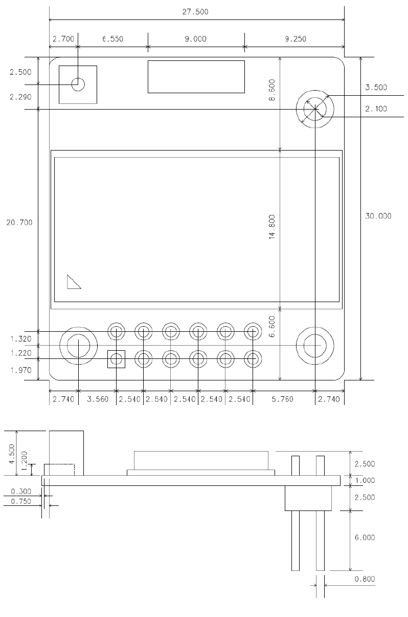
61
Appendix G: IW06 PCB mechanical drawing