SENA TECHNOLOGIES PARANIMSP1000 BLUETOOTH ACCESS POINT User Manual USERS MANUAL
Sena Technologies,Inc. BLUETOOTH ACCESS POINT USERS MANUAL
UserManual.wiki
>
SENA TECHNOLOGIES
>
PARANIMSP1000 User Manual
USERS MANUAL
Navigation menu
Upload a User Manual
Namespaces
Wiki Guide
HTML
PDF
Info
Views
User Manual
Discussion / Help
Navigation


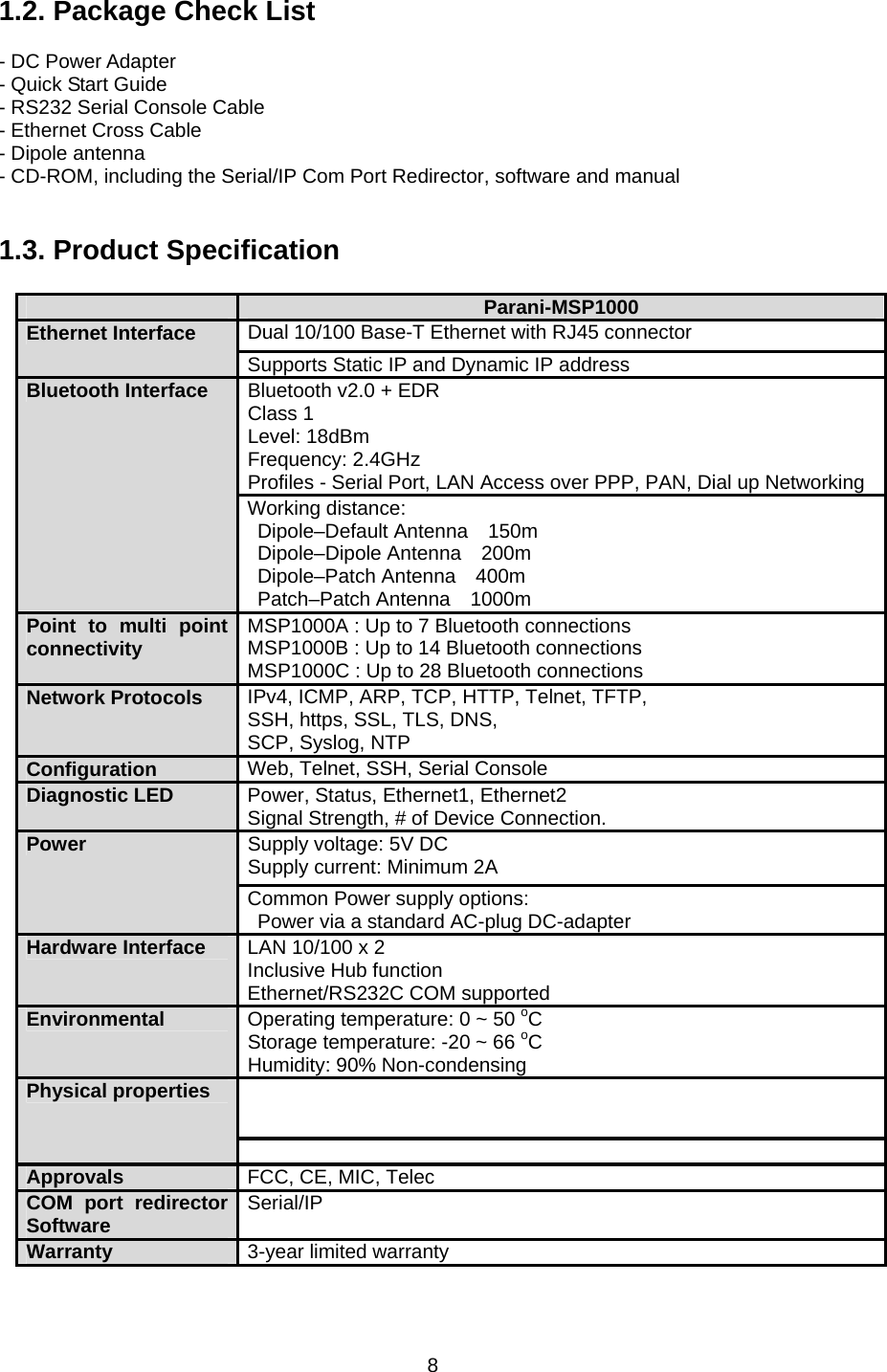
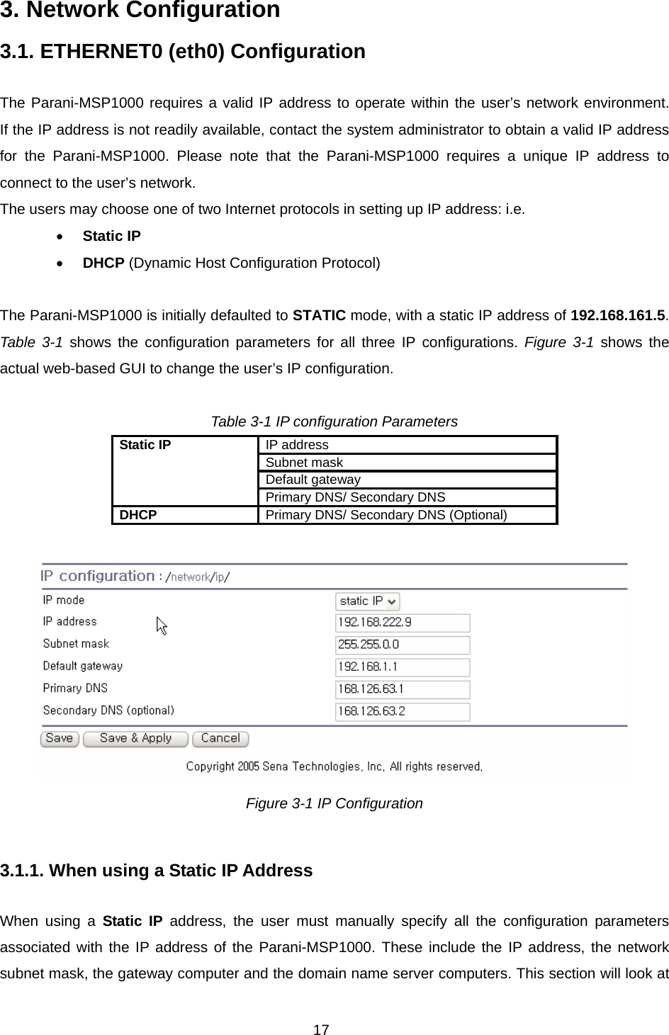
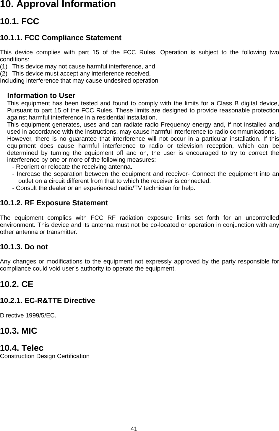
![10 2. Getting Started 2.1. External View 2.2. LED Indicators The Parani-MSP100 has a number of LED indicator lamps for status display. Table 2-1 describes function of each LED indicator lamp Table 2-1 LED indicator lamps Lamps Function Ethernet 0 Blinks whenever there is any activity on the Ethernet 0 port Ethernet Ethernet 1 Blinks whenever there is any activity on the Ethernet 1 port Signal Strength ? Bluetooth # of Bluetooth Connections Shows the number of Bluetooth sessions currently connected to the Parani-MSP1000 Status Solid GREEN, if system is running and ready to be used. System Power Solid RED, if power is supplied 2.3. Connecting the Hardware This section describes how to connect the Parani-MSP1000 to your equipment for initial testing. - Connect the power source to the Parani-MSP1000 - Connect the Parani-MSP1000 to Ethernet switch 2.3.1. Connecting the power Connect the power cable to the Parani-MSP1000. If the power is properly supplied, the [Power] lamp will light up solid green.](https://usermanual.wiki/SENA-TECHNOLOGIES/PARANIMSP1000/User-Guide-838054-Page-10.png)
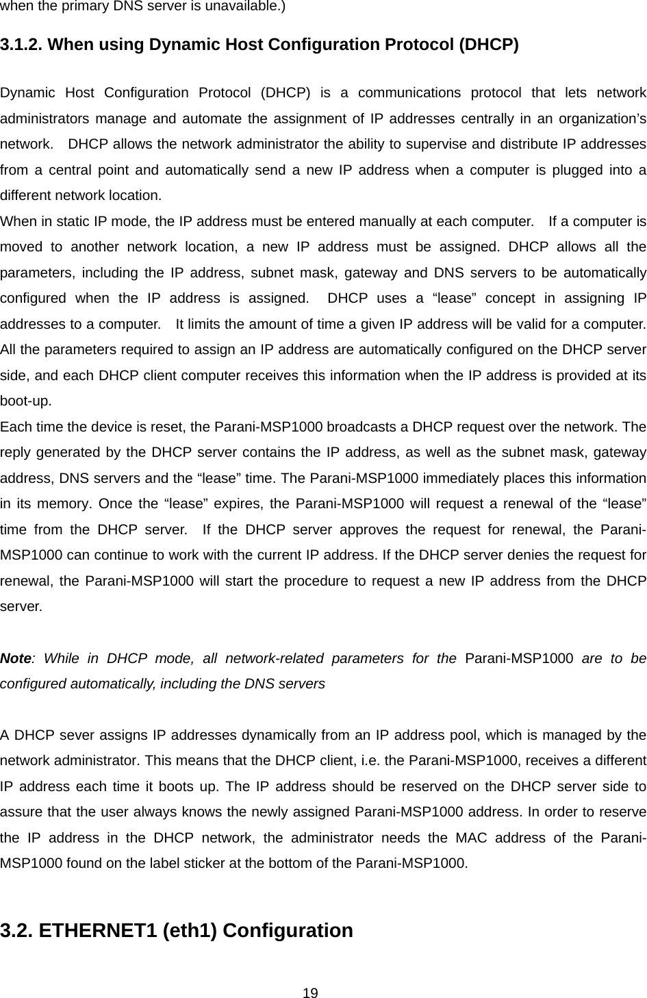
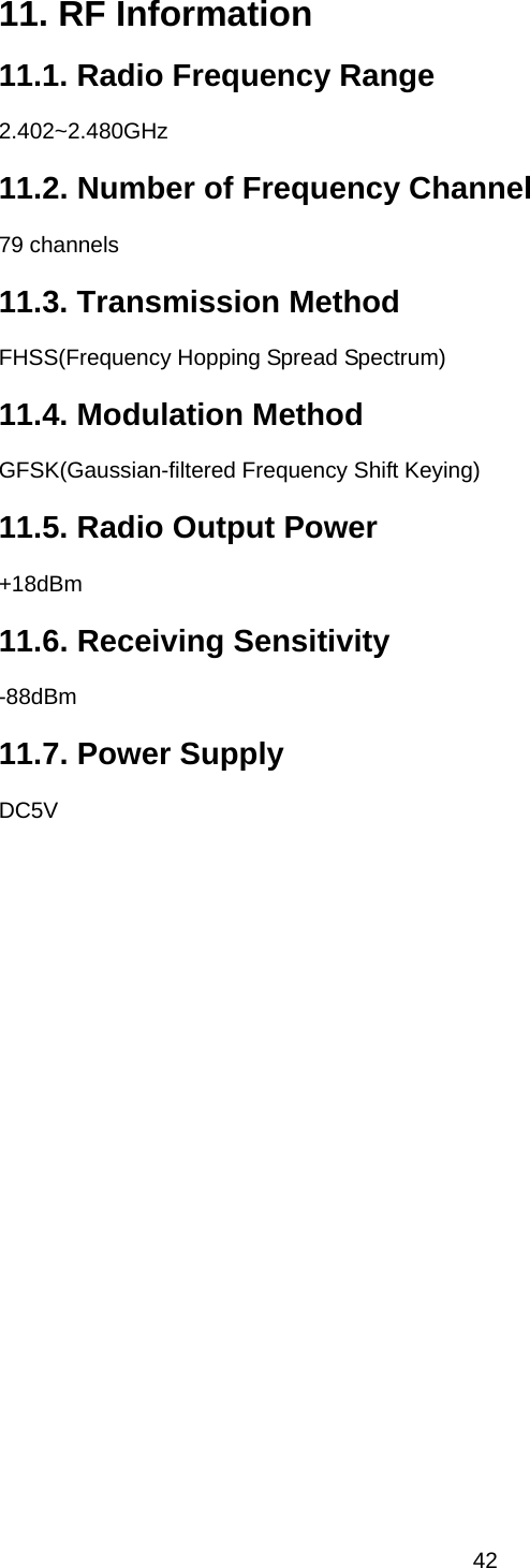
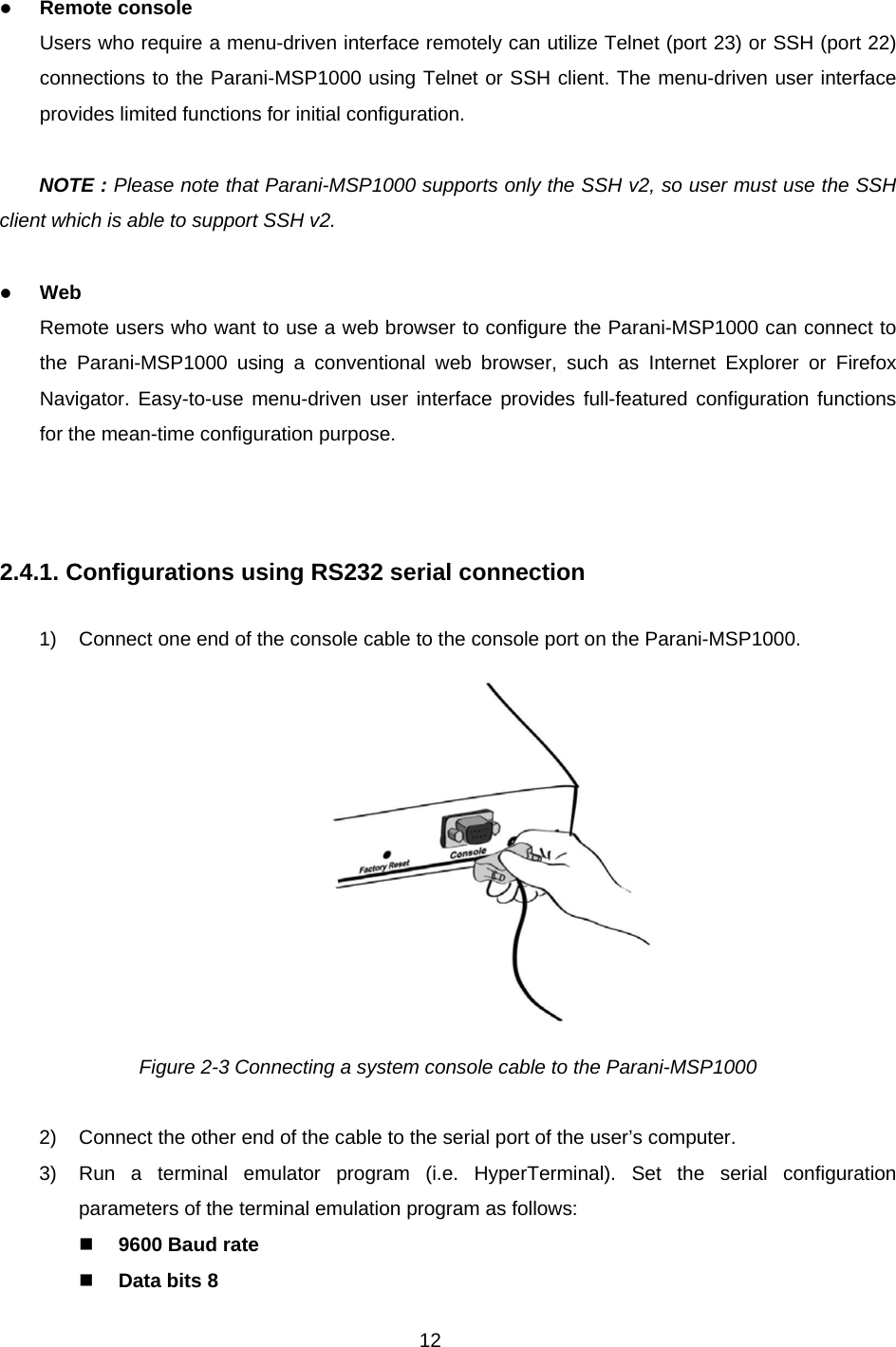
![11 Figure 2-1 Connecting the power to the Parani-MSP1000 2.3.2. Connecting to the network Plug one end of the Ethernet cable to the Parani-MSP1000 [Eth0] port. The other end of the Ethernet cable should be connected to a network port. If the cable is properly connected, the Parani-MSP1000 will have a valid connection to the Ethernet network. This will be indicated by: The [Eth0] blink to indicate incoming/outgoing Ethernet packets. Figure 2-2 Connecting a network cable to the MSP1000 2.4. Configurations The Parani-MSP1000 provides several paths to set up the box to make it work properly as expected. z RS232 Serial console If users want to set up the box before the network set-up, they can do it directly by using RS232 serial console cable provided in the package. This method is used when users want to set up the box initially or without network connection. The menu-driven user interface provides limited functions for initial configuration.](https://usermanual.wiki/SENA-TECHNOLOGIES/PARANIMSP1000/User-Guide-838054-Page-11.png)
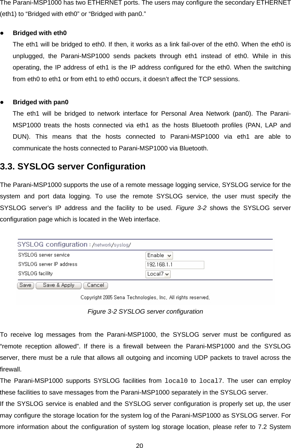
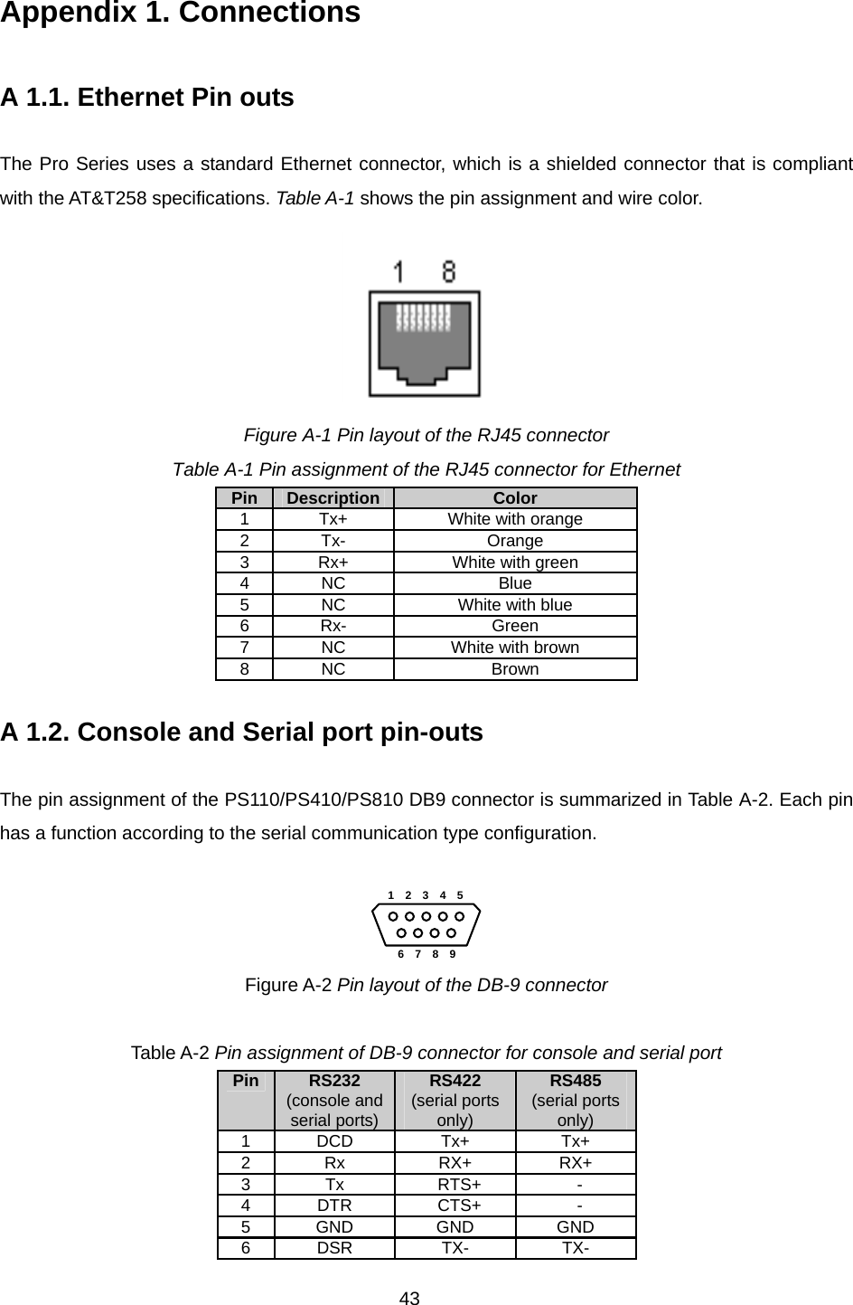
![13 Parity None Stop bits 1 No flow control 4) Press the [ENTER] key. 5) Enter your username and password to log into the Parani-MSP1000. The factory default user settings are as follows. Login: root Password: root 6) After login, users can use various shell commands in the CLI(Command Line interface). For details on the CLI, refer to the chapter 9, “CLI Guide”. 7) “editconf” command will allow you to enter the text-menu driven interface and the menu screen in #editconf [root@MSP1000 /]# editconf ------------------------------------------------------------------------------- Welcome to MSP1000 configuration page Current Time : 7/14/2007 12:22:56 Serial No. : msp1000-test1234 F/W Rev. : v1.0.0 MAC Addr.(eth0) : 00:01:95:AF:BF:DD IP Mode (eth0) : Static IP Addr.(eth0) : 192.168.161.5 ------------------------------------------------------------------------------- 1. Network configuration 2. System administration 3. System status & log 4. CF card configuration 5. Monitoring 6. Save changes 7. Exit without saving 8. Exit and apply changes 9. Exit and reboot <ESC> Back, <ENTER> Refresh --> 1 8) Select menu 1. [Network Configuration] and then proceed to [Ethernet 0] configuration to set up the IP address of the box. Users may set up the network configuration according to their environment. Once network set-up is done, users may access the box through telnet/ssh connection or by web browser. ------------------------------------------------------------------------------- Network Configuration ------------------------------------------------------------------------------- 1. ETHERNET 0 (eth0) configuration 2. ETHERNET 1 (eth1) configuration 3. Firewall configuration 4. TCP configuration <ESC> Back, <ENTER> Refresh --> 1 ------------------------------------------------------------------------------- ETHERNET 0 (eth0) configuration ------------------------------------------------------------------------------- 1. IP mode: Static IP 2. IP address: 192.168.14.123 3. Subnetmask: 255.255.0.0 4. Gateway: 192.168.1.1 5. Primary DNS: 168.126.63.1 6. Secondary DNS: 168.126.63.2 <ESC> Back, <ENTER> Refresh -->](https://usermanual.wiki/SENA-TECHNOLOGIES/PARANIMSP1000/User-Guide-838054-Page-13.png)
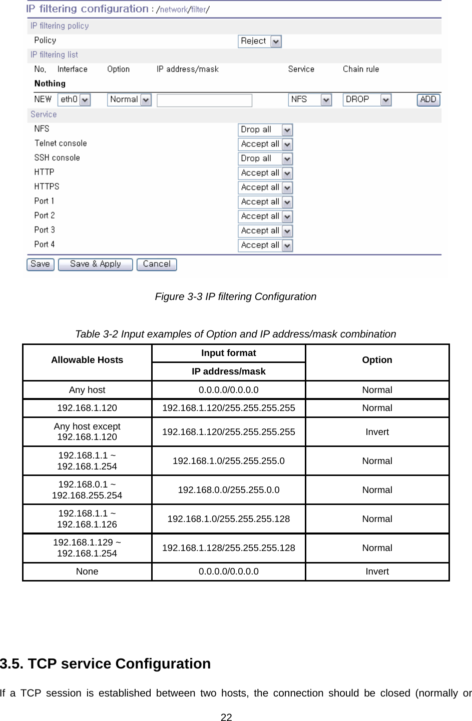
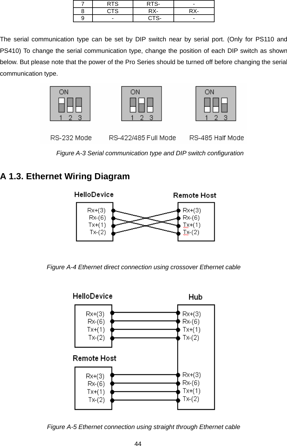
![14 From the main menu screen, the users may select a menu item for configuration of the Parani-MSP1000 parameters by selecting the menu number and pressing the [ENTER] key. In the submenu screen, users can configure the required parameters guided by online comments. NOTE: Be sure to perform “save” and “apply” command before you exit from editconf menu program. All the parameters can be stored into the non-volatile memory space of the box, but the settings will not be stored until users perform “save” command on the menu. All the configuration change will be effective after entering “apply” command on the menu. 2.4.2. Configurations using Ethernet connection The IP address of the Parani-MSP1000 must be known before users can access the box using the Remote console. The default IP address of the Parani-MSP1000 is 192.168.161.5. Once users know the IP address of the box, they can access to it either by using telnet/ssh program or web browser. The default user name and password is as same as the serial console interface as follows. root : root 1) Telnet/SSH Access The steps for accessing telnet/ssh interface is exactly same as the ones in serial console access. Please take steps from 5) to 8) in chapter 2.4.1 to get into the menu-driven user interface. 2) Web Access The Parani-MSP1000 supports both HTTP and HTTPS (HTTP over SSL) protocols.](https://usermanual.wiki/SENA-TECHNOLOGIES/PARANIMSP1000/User-Guide-838054-Page-14.png)

![16 menu bar is provided on the left side of the screen. The menu bar includes the uppermost configuration menu groups. Selecting an item on the menu bar opens a tree view of all the submenus available under each grouping. Selecting a submenu item will allow the user to modify parameter settings for that item. Every page will allow the user to [Save to Flash], [Save & apply] or [Cancel] their actions. After changing the configuration parameter values, the users must select [Save] to save the changed parameter values to the non-volatile memory. To apply all changes made, the user must select [Apply Changes]. This option is available on the bottom of the menu bar. Only when the user selects [Apply changes] will the new parameter values be applied to the Parani-MSP1000 configuration. Users also can select [Save & apply] to save parameters and apply changes in one step. If the user does not want to save the new parameter values, the user must opt to [Cancel]. All changes made will be lost and the previous values restored. But the changes that are already saved or applied cannot be canceled. 2.4.3. Configurations using Bluetooth wireless connection The Parani-MSP1000 provides PAN(Personal Area Network) profile service as a way to access the configuration interface of the box through TCP/IP using Bluetooth connection. Users may initially configure the box using Bluetooth connection when their PC or lap-top has Bluetooth communication capability. The following is the brief guide to do this way. 1) Hook up the power adapter to the Parani-MSP10000. Do not wire the Ethernet connection. 2) Search Parani-MSP1000 using Bluetooth Scan software and then connect to the device using [Network Access Point] protocol. 3) Make sure the connection is made, and then check the IP address of the PC or laptop. The Parani-MSP1000 has a built-in DHCP server, and it lease the 10.0.0.x IP address to the client computer. The default IP address of the Parani-MSP1000 in this PAN is 10.0.0.1. 4) Try to connect to the Parani-MSP1000 by IP address, 10.0.0.1 using web or telnet program. 5) Users can configure the box using wireless connection.](https://usermanual.wiki/SENA-TECHNOLOGIES/PARANIMSP1000/User-Guide-838054-Page-16.png)