Sena Technologies PARANIMSP1000 BLUETOOTH ACCESS POINT User Manual USERS MANUAL
Sena Technologies,Inc. BLUETOOTH ACCESS POINT USERS MANUAL
USERS MANUAL
Parani-MSP1000
For Wireless Multi-Serial Communications,
based on Bluetooth Technology
User Guide
Version 0.0.1
2007-05-28

2
User Guide for the Parani-MSP1000
Version 0.0.1
Firmware version 1.0.X
Last revised on August 16, 2007
Printed in Korea
Copyright
Copyright 2007, Sena Technologies, Inc. All rights reserved.
Sena Technologies reserves the right to make changes and improvements to its product without
providing notice.
Trademark
Parani™ is a trademark of Sena Technologies, Inc.
Windows® is a registered trademark of Microsoft Corporation.
Ethernet® is a registered trademark of XEROX Corporation.
Notice to Users
Proper back-up systems and necessary safety devices should be utilized to protect against injury,
death or property damage due to system failure. Such protection is the responsibility of the user.
This device is not approved for use as a life-support or medical system.
Any changes or modifications made to this device without the explicit approval or consent of Sena
Technologies will void Sena Technologies of any liability or responsibility of injury or loss caused by
any malfunction.
Technical Support
Sena Technologies, Inc.
210 Yangjae-dong, Seocho-gu
Seoul 137-130, Korea
Tel: (+82-2) 573-5422
Fax: (+82-2) 573-7710
E-Mail: support@sena.com
Website: http://www.sena.com

3
Revision History
Revision Date Name Description
V0.0.1 2007-08-16 Hanjun Yeom Initial Draft
4
Contents
1. Introduction 7
1.1. Overview ....................................................................................................................................7
1.2. Package Check List....................................................................................................................8
1.3. Product Specification..................................................................................................................8
2. Getting Started 10
2.1. External View ...........................................................................................................................10
2.2. LED Indicators..........................................................................................................................10
2.3. Connecting the Hardware ........................................................................................................10
2.3.1. Connecting to the network ...............................오류! 책갈피가 정의되어 있지 않습니다.
2.3.2. Connecting the power......................................오류! 책갈피가 정의되어 있지 않습니다.
2.3.3. Accessing the System console ........................오류! 책갈피가 정의되어 있지 않습니다.
2.3.4. Using the System console ...............................오류! 책갈피가 정의되어 있지 않습니다.
2.3.5. Using Remote console.....................................오류! 책갈피가 정의되어 있지 않습니다.
2.4. Accessing the Web Browser Management Interface .오류! 책갈피가 정의되어 있지 않습니다.
2.5. Serial Port...................................................................오류! 책갈피가 정의되어 있지 않습니다.
2.6. Reset/Reboot/Quit......................................................오류! 책갈피가 정의되어 있지 않습니다.
3. Network Configuration 10
3.1. ETHERNET0 (eth0) Configuration...........................................................................................17
3.1.1. When using a Static IP Address.....................................................................................17
3.1.2. When using Dynamic Host Configuration Protocol (DHCP)..........................................19
3.2. ETHERNET1 (eth1) Configuration...........................................................................................19
3.3. SYSLOG server Configuration.................................................................................................20
3.4. Firewall Configuration ..............................................................................................................21
3.5. TCP service Configuration .......................................................................................................22
4. Bluetooth Configuration 24
4.1. Overview ..................................................................................................................................24
4.2. Device Configuration................................................................................................................24
4.2.1. Bluetooth friendly name ...................................오류! 책갈피가 정의되어 있지 않습니다.
4.2.2. Inquiry scan......................................................오류! 책갈피가 정의되어 있지 않습니다.
4.2.3. Page scan ........................................................오류! 책갈피가 정의되어 있지 않습니다.
4.2.4. Authentication ..................................................오류! 책갈피가 정의되어 있지 않습니다.
4.2.5. Pass key (PIN code) ........................................오류! 책갈피가 정의되어 있지 않습니다.
4.2.6. Encryption ........................................................오류! 책갈피가 정의되어 있지 않습니다.
4.2.7. Available Bluetooth devices .............................오류! 책갈피가 정의되어 있지 않습니다.
4.3. Serial Port Profile (SPP) Configuration ....................................................................................24
4.3.1. Operation mode .............................................................................................................24
4.3.2. Operation mode – Initiate connection to unspecific devices..........................................25
4.3.3. Operation mode – Accept connection from unspecific devices .....................................28
4.3.4. Operation mode – Initiate/Accept connection to/from specific devices .........................28
4.3.5. Available Bluetooth devices .............................오류! 책갈피가 정의되어 있지 않습니다.
4.4. PAN/DUN/LAP Configuration ...................................................................................................30
4.4.1. Private address ..............................................................................................................30
4.4.2. Personal Area Networking (PAN)...................................................................................30
4.4.3. Dial-Up Networking (DUN).............................................................................................30
4.4.4. LAN Access over PPP (LAP) .........................................................................................30
5. CF card Configuration 31
5.1. When using a flash memory card.............................................................................................31
6. System administration 32
6.1. Device name ............................................................................................................................32
6.2. User management....................................................................................................................32
5
6.2.1. Adding a new user .........................................................................................................32
6.2.2. Removing a user............................................................................................................32
6.2.3. Editing a user .................................................................................................................32
6.3. Certificates ...............................................................................................................................32
6.3.1. Changing certificate .......................................................................................................32
6.3.2. Changing private key .....................................................................................................32
6.3.3. Uploading a new Trusted CA certificate.........................................................................32
6.3.4. Removing a Trusted CA certificate ................................................................................32
6.4. Date and Time..........................................................................................................................32
6.5. Configuration management......................................................................................................32
6.5.1. Exporting configuration ..................................................................................................32
6.5.2. Importing configuration ..................................................................................................32
6.5.3. Reset to factory-default..................................................................................................32
6.6. Firmware upgrade ....................................................................................................................32
6.7. Change password ....................................................................................................................32
7. System status & log 33
7.1. System status...........................................................................................................................33
7.2. System logging.........................................................................................................................33
7.2.1. System log location........................................................................................................33
7.2.2. System log buffer size....................................................................................................33
7.2.3. Lessen system log .........................................................................................................33
7.3. Bluetooth connection monitoring..............................................................................................33
8. System statistics 34
8.1. Network interfaces....................................................................................................................34
8.2. IP ..............................................................................................................................................34
8.3. ICMP ........................................................................................................................................35
8.4. TCP ..........................................................................................................................................37
8.5. UDP..........................................................................................................................................38
9. CLI guide 39
9.1. Introduction...............................................................................................................................39
9.2. Flash partitions.........................................................................................................................39
9.3. Supported Linux Utilities ..........................................................................................................39
9.3.1. Shell & shell utilities .......................................................................................................39
9.3.2. File and dis utilities.........................................................................................................39
9.3.3. System utilities ...............................................................................................................39
9.3.4. Network utilities..............................................................................................................39
9.3.5. Blutooth utilities..............................................................................................................39
9.4. Accessing CLI...........................................................................................................................39
10. Approval Information 41
10.1. FCC ........................................................................................................................................41
10.1.1. FCC Compliance Statement ........................................................................................41
10.1.2. RF Exposure Statement...............................................................................................41
10.1.3. Do not...........................................................................................................................41
10.2. CE ..........................................................................................................................................41
10.2.1. EC-R&TTE Directive....................................................................................................41
10.3. MIC.........................................................................................................................................41
10.4. Telec .......................................................................................................................................41
11. RF Information 42
11.1. Radio Frequency Range.........................................................................................................42
11.2. Number of Frequency Channel ..............................................................................................42
11.3. Transmission Method .............................................................................................................42
11.4. Modulation Method.................................................................................................................42
11.5. Radio Output Power ...............................................................................................................42
11.6. Receiving Sensitivity...............................................................................................................42
11.7. Power Supply .........................................................................................................................42
6
Appendix 1. Connections 43
A 1.1. Ethernet Pin outs...................................................................................................................43
A 1.2. Console and Serial port pin-outs...........................................................................................43
A 1.3. Ethernet Wiring Diagram.......................................................................................................44
Appendix 2. Parani-MSP1000 Configuration files 45
A 2.1. ip.conf....................................................................................................................................45
Appendix 3. Well-known port numbers 46
Appendix 4. Guide to the Bios menu program 47
Appendix 5: Warranty 48
A.5.1. GENERAL WARRANTY POLICY .........................................................................................48
A.5.2. LIMITATION OF LIABILITY...................................................................................................48
A.5.3. HARDWARE PRODUCT WARRANTY DETAILS.................................................................48
A.5.4. SOFTWARE PRODUCT WARRANTY DETAILS .................................................................49
A.5.5. THIRD-PARTY SOFTWARE PRODUCT WARRANTY DETAILS.........................................49
7
1. Introduction
1.1. Overview
The Parani-MSP1000 series is a Bluetooth Access Point to enable Bluetooth devices to be
connected to 10/100Mbps Ethernet network. Parani-MSP1000 supports 7, 14, and 28 Bluetooth
connections according to the model, and it supports up to 3Mbps throughput through Bluetooth
2.0+EDR specification. The Parani-MSP1000 series is a class 1 Bluetooth device that supports 150m
using basic dipole antenna and up to 1 km using patch antenna. The Parani-MSP1000 series supports
such various profiles as Serial Port (SPP), LAN Access over PPP (LAP), Dial-up Networking (DUN),
Personal Area Networking (PAN) and FTP for various applications.
For ideal serial cable replacement applications, COM/TTY port redirector software is provided for free
for Windows/Linux. The Bluetooth connection downside of the Parani-MSP1000 may be transferred to
the specified multiple hosts on the network through various TCP/IP connections such as raw TCP or
SSL/TLS or SSH.
For mission-critical applications requiring secure data communication, the Parani-MSP1000
supports SSLv2 SSLv3, TLSv1, SSHv1 and SSHv2 for data encryption. In addition, IP address filtering
function is provided for protecting unintentional data streams to be transmitted to the Parani-MSP1000.
The dual Ethernet, fail-over feature may be also helpful to the users who want to apply this box in
mission-critical fail-safe applications.
The Parani-MSP1000 series is based on embedded Linux system and it supports versatile Python
script engine and corresponding libraries. Hence, users may customize the function of the box easily
by using Python script. Users may run their Python script in 2MB user space inside of the box, and
then run various system and network functions.
The Parani-MSP1000 provides you with full-featured system management functionality of system
status display, firmware upgrade, remote reset and system log display by using various ways such as
telnet, SSH, serial console port or web. You can easily configure and administrate the Parani-
MSP1000, with the full-featured management functions of status monitor, remote reset, error log
monitor and firmware upgrade by using Telnet and serial console port under the password protection
support.
Typical application areas of the Parani-MSP1000 Series are:
- Industrial automation
- Wireless building automation
- Wireless POS system
- Wireless printing
- Wireless factory monitoring
- Wireless machine monitoring
- Security/Access control systems
- General data acquisition application
- Truck/Bus monitoring system
- Car diagnostics
Please note that this manual assumes user knowledge of Bluetooth and TCP/IP Internetworking
protocols.

8
1.2. Package Check List
- DC Power Adapter
- Quick Start Guide
- RS232 Serial Console Cable
- Ethernet Cross Cable
- Dipole antenna
- CD-ROM, including the Serial/IP Com Port Redirector, software and manual
1.3. Product Specification
Parani-MSP1000
Dual 10/100 Base-T Ethernet with RJ45 connector
Ethernet Interface
Supports Static IP and Dynamic IP address
Bluetooth v2.0 + EDR
Class 1
Level: 18dBm
Frequency: 2.4GHz
Profiles - Serial Port, LAN Access over PPP, PAN, Dial up Networking
Bluetooth Interface
Working distance:
Dipole–Default Antenna 150m
Dipole–Dipole Antenna 200m
Dipole–Patch Antenna 400m
Patch–Patch Antenna 1000m
Point to multi point
connectivity MSP1000A : Up to 7 Bluetooth connections
MSP1000B : Up to 14 Bluetooth connections
MSP1000C : Up to 28 Bluetooth connections
Network Protocols IPv4, ICMP, ARP, TCP, HTTP, Telnet, TFTP,
SSH, https, SSL, TLS, DNS,
SCP, Syslog, NTP
Configuration Web, Telnet, SSH, Serial Console
Diagnostic LED Power, Status, Ethernet1, Ethernet2
Signal Strength, # of Device Connection.
Supply voltage: 5V DC
Supply current: Minimum 2A
Power
Common Power supply options:
Power via a standard AC-plug DC-adapter
Hardware Interface LAN 10/100 x 2
Inclusive Hub function
Ethernet/RS232C COM supported
Environmental Operating temperature: 0 ~ 50 oC
Storage temperature: -20 ~ 66 oC
Humidity: 90% Non-condensing
Physical properties
Approvals FCC, CE, MIC, Telec
COM port redirector
Software Serial/IP
Warranty 3-year limited warranty

9
Note *:
Bluetooth v2.0 supports improved AFH function. AFH function is to mitigate the interference
between WiFi and Bluetooth radios by automatically avoiding the active WiFi channel from
Bluetooth link. However, AFH does not provide a complete solution making WiFi and Bluetooth
work together in harmony. It is highly recommended for users to test their wireless system
enough before deployment since the overall system performance is affected by various
environmental factors such as distance between them.
10
2. Getting Started
2.1. External View
2.2. LED Indicators
The Parani-MSP100 has a number of LED indicator lamps for status display. Table 2-1 describes
function of each LED indicator lamp
Table 2-1 LED indicator lamps
Lamps Function
Ethernet 0 Blinks whenever there is any activity on the Ethernet 0 port
Ethernet Ethernet 1 Blinks whenever there is any activity on the Ethernet 1 port
Signal Strength ?
Bluetooth # of Bluetooth
Connections Shows the number of Bluetooth sessions currently connected to the
Parani-MSP1000
Status Solid GREEN, if system is running and ready to be used.
System Power Solid RED, if power is supplied
2.3. Connecting the Hardware
This section describes how to connect the Parani-MSP1000 to your equipment for initial testing.
- Connect the power source to the Parani-MSP1000
- Connect the Parani-MSP1000 to Ethernet switch
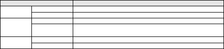
2.3.1. Connecting the power
Connect the power cable to the Parani-MSP1000. If the power is properly supplied, the [Power] lamp
will light up solid green.
11
Figure 2-1 Connecting the power to the Parani-MSP1000
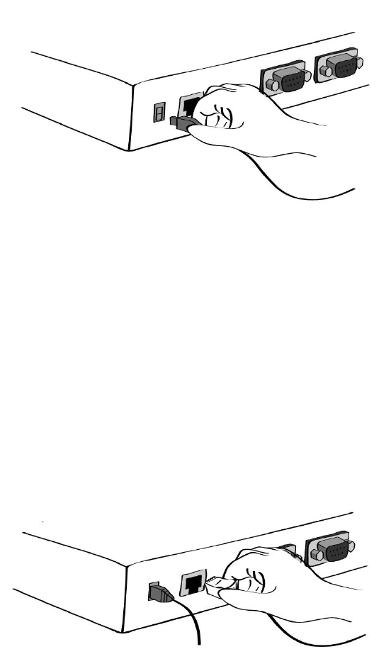
2.3.2. Connecting to the network
Plug one end of the Ethernet cable to the Parani-MSP1000 [Eth0] port. The other end of the Ethernet
cable should be connected to a network port. If the cable is properly connected, the Parani-MSP1000
will have a valid connection to the Ethernet network. This will be indicated by:
The [Eth0] blink to indicate incoming/outgoing Ethernet packets.
Figure 2-2 Connecting a network cable to the MSP1000
2.4. Configurations
The Parani-MSP1000 provides several paths to set up the box to make it work properly as expected.
z RS232 Serial console
If users want to set up the box before the network set-up, they can do it directly by using RS232
serial console cable provided in the package. This method is used when users want to set up the
box initially or without network connection. The menu-driven user interface provides limited
functions for initial configuration.
12
z Remote console
Users who require a menu-driven interface remotely can utilize Telnet (port 23) or SSH (port 22)
connections to the Parani-MSP1000 using Telnet or SSH client. The menu-driven user interface
provides limited functions for initial configuration.
NOTE : Please note that Parani-MSP1000 supports only the SSH v2, so user must use the SSH
client which is able to support SSH v2.
z Web
Remote users who want to use a web browser to configure the Parani-MSP1000 can connect to
the Parani-MSP1000 using a conventional web browser, such as Internet Explorer or Firefox
Navigator. Easy-to-use menu-driven user interface provides full-featured configuration functions
for the mean-time configuration purpose.
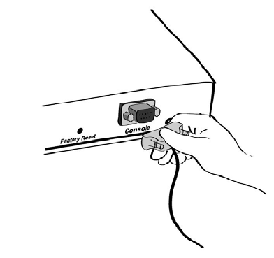
2.4.1. Configurations using RS232 serial connection
1) Connect one end of the console cable to the console port on the Parani-MSP1000.
Figure 2-3 Connecting a system console cable to the Parani-MSP1000
2) Connect the other end of the cable to the serial port of the user’s computer.
3) Run a terminal emulator program (i.e. HyperTerminal). Set the serial configuration
parameters of the terminal emulation program as follows:
9600 Baud rate
Data bits 8

13
Parity None
Stop bits 1
No flow control
4) Press the [ENTER] key.
5) Enter your username and password to log into the Parani-MSP1000. The factory default user
settings are as follows.
Login: root Password: root
6) After login, users can use various shell commands in the CLI(Command Line interface). For
details on the CLI, refer to the chapter 9, “CLI Guide”.
7) “editconf” command will allow you to enter the text-menu driven interface and the menu
screen in #editconf
[root@MSP1000 /]# editconf
-------------------------------------------------------------------------------
Welcome to MSP1000 configuration page
Current Time : 7/14/2007 12:22:56 Serial No. : msp1000-test1234
F/W Rev. : v1.0.0 MAC Addr.(eth0) : 00:01:95:AF:BF:DD
IP Mode (eth0) : Static IP Addr.(eth0) : 192.168.161.5
-------------------------------------------------------------------------------
1. Network configuration
2. System administration
3. System status & log
4. CF card configuration
5. Monitoring
6. Save changes
7. Exit without saving
8. Exit and apply changes
9. Exit and reboot
<ESC> Back, <ENTER> Refresh
--> 1
8) Select menu 1. [Network Configuration] and then proceed to [Ethernet 0] configuration to set
up the IP address of the box. Users may set up the network configuration according to their
environment. Once network set-up is done, users may access the box through telnet/ssh
connection or by web browser.
-------------------------------------------------------------------------------
Network Configuration
-------------------------------------------------------------------------------
1. ETHERNET 0 (eth0) configuration
2. ETHERNET 1 (eth1) configuration
3. Firewall configuration
4. TCP configuration
<ESC> Back, <ENTER> Refresh
--> 1
-------------------------------------------------------------------------------
ETHERNET 0 (eth0) configuration
-------------------------------------------------------------------------------
1. IP mode: Static IP
2. IP address: 192.168.14.123
3. Subnetmask: 255.255.0.0
4. Gateway: 192.168.1.1
5. Primary DNS: 168.126.63.1
6. Secondary DNS: 168.126.63.2
<ESC> Back, <ENTER> Refresh
-->
14
From the main menu screen, the users may select a menu item for configuration of the Parani-
MSP1000 parameters by selecting the menu number and pressing the [ENTER] key. In the submenu
screen, users can configure the required parameters guided by online comments.
NOTE: Be sure to perform “save” and “apply” command before you exit from editconf menu
program. All the parameters can be stored into the non-volatile memory space of the box, but the
settings will not be stored until users perform “save” command on the menu. All the configuration
change will be effective after entering “apply” command on the menu.
2.4.2. Configurations using Ethernet connection
The IP address of the Parani-MSP1000 must be known before users can access the box using the
Remote console. The default IP address of the Parani-MSP1000 is 192.168.161.5. Once users know
the IP address of the box, they can access to it either by using telnet/ssh program or web browser.
The default user name and password is as same as the serial console interface as follows.
root : root
1) Telnet/SSH Access
The steps for accessing telnet/ssh interface is exactly same as the ones in serial console access.
Please take steps from 5) to 8) in chapter 2.4.1 to get into the menu-driven user interface.
2) Web Access
The Parani-MSP1000 supports both HTTP and HTTPS (HTTP over SSL) protocols.
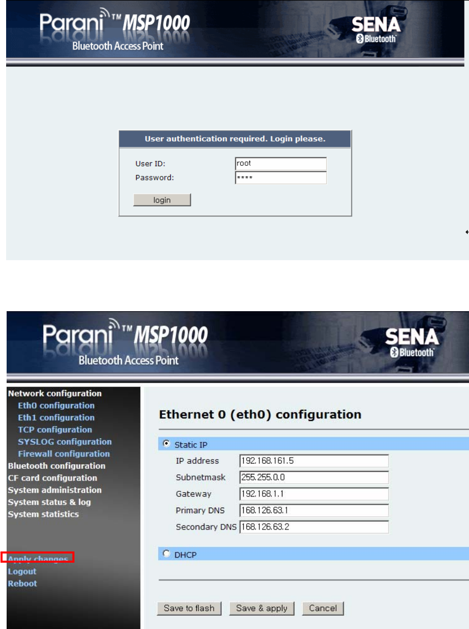
15
Figure 2-4 Login screen of the Parani-MSP1000 web management
Figure 2-5 The Parani-MSP1000 Series web management screen
Figure 2-5 shows the configuration homepage of the Parani-MSP1000 Web management interface. A
16
menu bar is provided on the left side of the screen. The menu bar includes the uppermost
configuration menu groups. Selecting an item on the menu bar opens a tree view of all the submenus
available under each grouping. Selecting a submenu item will allow the user to modify parameter
settings for that item. Every page will allow the user to [Save to Flash], [Save & apply] or [Cancel] their
actions. After changing the configuration parameter values, the users must select [Save] to save the
changed parameter values to the non-volatile memory.
To apply all changes made, the user must select [Apply Changes]. This option is available on the
bottom of the menu bar. Only when the user selects [Apply changes] will the new parameter values be
applied to the Parani-MSP1000 configuration. Users also can select [Save & apply] to save
parameters and apply changes in one step.
If the user does not want to save the new parameter values, the user must opt to [Cancel]. All changes
made will be lost and the previous values restored. But the changes that are already saved or applied
cannot be canceled.
2.4.3. Configurations using Bluetooth wireless connection
The Parani-MSP1000 provides PAN(Personal Area Network) profile service as a way to access
the configuration interface of the box through TCP/IP using Bluetooth connection. Users may initially
configure the box using Bluetooth connection when their PC or lap-top has Bluetooth communication
capability. The following is the brief guide to do this way.
1) Hook up the power adapter to the Parani-MSP10000. Do not wire the Ethernet connection.
2) Search Parani-MSP1000 using Bluetooth Scan software and then connect to the device using
[Network Access Point] protocol.
3) Make sure the connection is made, and then check the IP address of the PC or laptop.
The Parani-MSP1000 has a built-in DHCP server, and it lease the 10.0.0.x IP address to the
client computer. The default IP address of the Parani-MSP1000 in this PAN is 10.0.0.1.
4) Try to connect to the Parani-MSP1000 by IP address, 10.0.0.1 using web or telnet program.
5) Users can configure the box using wireless connection.
17
3. Network Configuration
3.1. ETHERNET0 (eth0) Configuration
The Parani-MSP1000 requires a valid IP address to operate within the user’s network environment.
If the IP address is not readily available, contact the system administrator to obtain a valid IP address
for the Parani-MSP1000. Please note that the Parani-MSP1000 requires a unique IP address to
connect to the user’s network.
The users may choose one of two Internet protocols in setting up IP address: i.e.
• Static IP
• DHCP (Dynamic Host Configuration Protocol)
The Parani-MSP1000 is initially defaulted to STATIC mode, with a static IP address of 192.168.161.5.
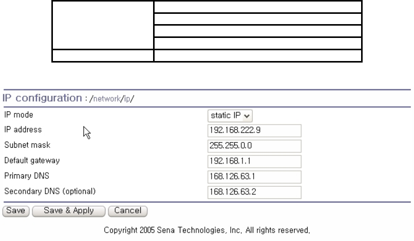
Table 3-1 shows the configuration parameters for all three IP configurations. Figure 3-1 shows the
actual web-based GUI to change the user’s IP configuration.
Table 3-1 IP configuration Parameters
IP address
Subnet mask
Default gateway
Static IP
Primary DNS/ Secondary DNS
DHCP Primary DNS/ Secondary DNS (Optional)
Figure 3-1 IP Configuration
3.1.1. When using a Static IP Address
When using a Static IP address, the user must manually specify all the configuration parameters
associated with the IP address of the Parani-MSP1000. These include the IP address, the network
subnet mask, the gateway computer and the domain name server computers. This section will look at

18
each of these in more detail.
Note: The Parani-MSP1000 will attempt to locate all this information every time it is turned on.
z IP address
A Static IP address acts as a “static” or permanent identification number. This number is assigned to
a computer to act as its location address on the network. Computers use these IP addresses to
identify and talk to each other on a network. Therefore, it is imperative that the selected IP address be
both unique and valid in a network environment.
Note: 192.168.1.x, 172.16.x.x and 10.x.x.x will never be assigned by and ISP (Internet Service
Provider). IP addresses using this form are considered private. Actual applications of the Parani-
MSp1000 may require access to public network, such as the Internet. If so, a valid public IP address
must be assigned to the user’s computer. A public IP address is usually purchased or leased from a
local ISP.
z Subnet mask
A subnet represents all the network hosts in one geographic location, such as a building or local area
network (LAN). The Parani-MSP1000 will use the subnet mask setting to verify the origin of all packets.
If the desired TCP/IP host specified in the packet is in the same geographic location (on the local
network segment) as defined by the subnet mask, the Parani-MSP1000 will establish a direct
connection. If the desired TCP/IP host specified in the packet is not identified as belonging on the local
network segment, a connection is established through the given default gateway.
z Default gateway
A gateway is a network point that acts as a portal to another network. This point is usually the
computer or computers that control traffic within a network or a local ISP (Internet service provider).
The Parani-MSP1000 uses the IP address of the default gateway computer to communicate with hosts
outside the local network environment. Refer to the network administrator for a valid gateway IP
address.
z Primary and Secondary DNS
The DNS (Domain Name System) server is used to locate and translate the correct IP address for a
requested web site address. A domain name is the web address (i.e. www.yahoo.com) and is
usually easier to remember. The DNS server is the host that can translate such text-based domain
names into the numeric IP addresses for a TCP/IP connection.
The IP address of the DNS server must be able to access the host site with the provided domain
name. The Parani-MSP1000 provides the ability to configure the required IP addresses of both the
Primary and Secondary DNS servers addresses. (The secondary DNS server is specified for use
19
when the primary DNS server is unavailable.)
3.1.2. When using Dynamic Host Configuration Protocol (DHCP)
Dynamic Host Configuration Protocol (DHCP) is a communications protocol that lets network
administrators manage and automate the assignment of IP addresses centrally in an organization’s
network. DHCP allows the network administrator the ability to supervise and distribute IP addresses
from a central point and automatically send a new IP address when a computer is plugged into a
different network location.
When in static IP mode, the IP address must be entered manually at each computer. If a computer is
moved to another network location, a new IP address must be assigned. DHCP allows all the
parameters, including the IP address, subnet mask, gateway and DNS servers to be automatically
configured when the IP address is assigned. DHCP uses a “lease” concept in assigning IP
addresses to a computer. It limits the amount of time a given IP address will be valid for a computer.
All the parameters required to assign an IP address are automatically configured on the DHCP server
side, and each DHCP client computer receives this information when the IP address is provided at its
boot-up.
Each time the device is reset, the Parani-MSP1000 broadcasts a DHCP request over the network. The
reply generated by the DHCP server contains the IP address, as well as the subnet mask, gateway
address, DNS servers and the “lease” time. The Parani-MSP1000 immediately places this information
in its memory. Once the “lease” expires, the Parani-MSP1000 will request a renewal of the “lease”
time from the DHCP server. If the DHCP server approves the request for renewal, the Parani-
MSP1000 can continue to work with the current IP address. If the DHCP server denies the request for
renewal, the Parani-MSP1000 will start the procedure to request a new IP address from the DHCP
server.
Note: While in DHCP mode, all network-related parameters for the Parani-MSP1000 are to be
configured automatically, including the DNS servers
A DHCP sever assigns IP addresses dynamically from an IP address pool, which is managed by the
network administrator. This means that the DHCP client, i.e. the Parani-MSP1000, receives a different
IP address each time it boots up. The IP address should be reserved on the DHCP server side to
assure that the user always knows the newly assigned Parani-MSP1000 address. In order to reserve
the IP address in the DHCP network, the administrator needs the MAC address of the Parani-
MSP1000 found on the label sticker at the bottom of the Parani-MSP1000.
3.2. ETHERNET1 (eth1) Configuration
20
The Parani-MSP1000 has two ETHERNET ports. The users may configure the secondary ETHERNET
(eth1) to “Bridged with eth0” or “Bridged with pan0.”
z Bridged with eth0
The eth1 will be bridged to eth0. If then, it works as a link fail-over of the eth0. When the eth0 is
unplugged, the Parani-MSP1000 sends packets through eth1 instead of eth0. While in this
operating, the IP address of eth1 is the IP address configured for the eth0. When the switching
from eth0 to eth1 or from eth1 to eth0 occurs, it doesn’t affect the TCP sessions.
z Bridged with pan0
The eth1 will be bridged to network interface for Personal Area Network (pan0). The Parani-
MSP1000 treats the hosts connected via eth1 as the hosts Bluetooth profiles (PAN, LAP and
DUN). This means that the hosts connected to Parani-MSP1000 via eth1 are able to
communicate the hosts connected to Parani-MSP1000 via Bluetooth.
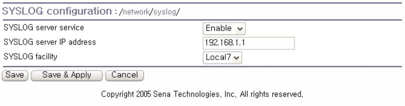
3.3. SYSLOG server Configuration
The Parani-MSP1000 supports the use of a remote message logging service, SYSLOG service for the
system and port data logging. To use the remote SYSLOG service, the user must specify the
SYSLOG server’s IP address and the facility to be used. Figure 3-2 shows the SYSLOG server
configuration page which is located in the Web interface.
Figure 3-2 SYSLOG server configuration
To receive log messages from the Parani-MSP1000, the SYSLOG server must be configured as
“remote reception allowed”. If there is a firewall between the Parani-MSP1000 and the SYSLOG
server, there must be a rule that allows all outgoing and incoming UDP packets to travel across the
firewall.
The Parani-MSP1000 supports SYSLOG facilities from local0 to local7. The user can employ
these facilities to save messages from the Parani-MSP1000 separately in the SYSLOG server.
If the SYSLOG service is enabled and the SYSLOG server configuration is properly set up, the user
may configure the storage location for the system log of the Parani-MSP1000 as SYSLOG server. For
more information about the configuration of system log storage location, please refer to 7.2 System
21
logging.
3.4. Firewall Configuration
The Parani-MSP1000 prevents unauthorized access using an IP address based filtering method. The
users can allow one of the following scenarios by changing the parameter settings:
- Any host cannot access a specific service of the Parani-MSP1000
- Only one host of a specific IP address can access a specific service of the Parani-MSP1000
- Hosts on a specific subnet can access a specific service of the Parani-MSP1000
- Any host can access a specific service of the Parani-MSP1000
The firewall feature is intended to control access to Telnet console, SSH console, Web server or each
Serial Port Profile session, which may be enabled or disabled. The factory default of the firwall feature
is “All services and ports are accessible from any host”.
The meanings of each parameter in IP filtering configuration are as follows,
z Interface
Apply IP filtering rule to the incoming packet of Parani-MSP1000. This is configurable one of
eth0 or pan0.
z Option and IP address/mask
Input field to describe a specific range of host on the network. The user may allow a host or a
group of hosts to access the Parani-MSP1000. The user must then enter the IP address and
subnet of access. Any user on a remote host must stay in the specified subnet boundary to
access the Parani-MSP1000. To allow only a specific host to access the Parani-MSP1000,
enter the IP address of the specific host and just give 255.255.255.255 for the subnet with
Normal option. To allow any hosts to have access to the Parani-MSP1000, give 0.0.0.0 for both
of the IP address and subnet with Normal option also. Refer to Table 3-2 for more details.
z Port
The TCP port number to which will be applied to the firewall rule. User can select one of
23(Telnet), 22(SSH), 80(HTTP), 443(HTTPS) or each Serial Port Profile session.
z Chain rule
Set the basic rule for the host to access the Parani-MSP1000 as one of Accept, Drop or Reject.
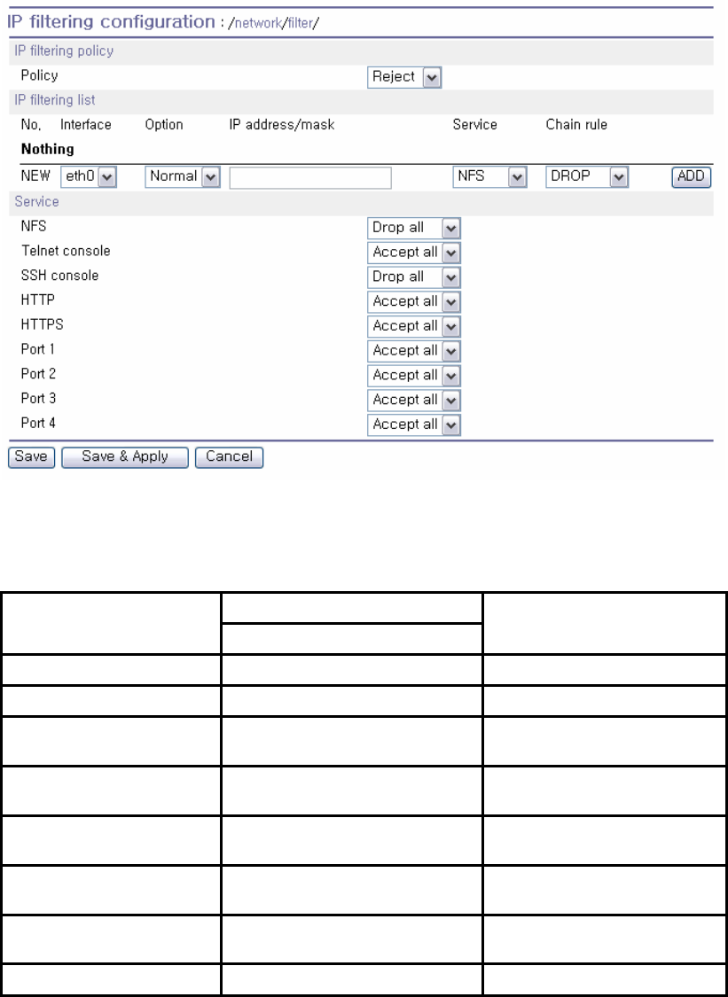
22
Figure 3-3 IP filtering Configuration
Table 3-2 Input examples of Option and IP address/mask combination
Input format
Allowable Hosts IP address/mask Option
Any host 0.0.0.0/0.0.0.0 Normal
192.168.1.120 192.168.1.120/255.255.255.255 Normal
Any host except
192.168.1.120 192.168.1.120/255.255.255.255 Invert
192.168.1.1 ~
192.168.1.254 192.168.1.0/255.255.255.0 Normal
192.168.0.1 ~
192.168.255.254 192.168.0.0/255.255.0.0 Normal
192.168.1.1 ~
192.168.1.126 192.168.1.0/255.255.255.128 Normal
192.168.1.129 ~
192.168.1.254 192.168.1.128/255.255.255.128 Normal
None 0.0.0.0/0.0.0.0 Invert
3.5. TCP service Configuration
If a TCP session is established between two hosts, the connection should be closed (normally or
23
abnormally) by either of the hosts to prevent the lock-up of the corresponding TCP port. To prevent
this type of lock-up situation, the Parani-MSP1000 provides a TCP “keep-alive” feature. The Parani-
MSP1000 will send packets back and forth through the network periodically to confirm that the network
exists . The corresponding TCP session is closed automatically if there’s no response from the remote
host.
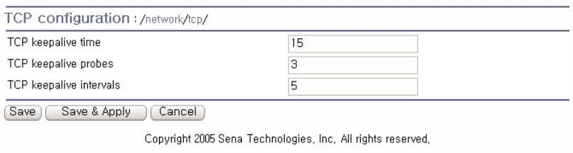
To use the TCP “keep-alive” feature with the Parani-MSP1000, the users should configure three
parameters as follows:
z TCP keep-alive time:
This represents the time interval between the last data transmission and keep-alive packet
submissions by the Parani-MSP1000. These “keep-alive” messages are sent to the remote host
to confirm that the session is still open. The default time value is 15 sec.
z TCP “keep-alive” probes:
This represents how many “keep-alive” probes will be sent to the remote host, until it decides that
the connection is dead. Multiplied with the “TCP ‘keep-alive’ intervals”, this gives the time that a
link is forced to close after a “keep-alive” packet has been sent for the first time. The default is 3
times
z TCP keep-alive intervals:
This represents the waiting period until a “keep-alive” packet is retransmitted. The default value is
5 seconds.
By default, the Parani-MSP1000 will send the keep-alive packets 3 times with 5 seconds interval after
15 seconds have elapsed since the time when there’s no data transmitted back and forth.
Figure 3-4 TCP keep-alive configuration
24
4. Bluetooth Configuration
4.1. Overview
4.2. Device Configuration
This menu is the configuration for the Bluetooth devices embedded in the Parani-MSP1000.
z Bluetooth friendly name
The device name. %h inserts the host name (device name) configured in the Device name
configuration. %d inserts the device id.
z Inquiry scan
When this is enabled, the Parani-MSP1000 is “discoverable.”
z Page scan
When this is enabled, the Parani-MSP1000 is “connectable to.”
z Authentication
When this is enabled, the Parani-MSP1000 require pass key (PIN code) for incoming connection.
If the pass key is incorrect, the connection will be rejected.
z Pass key
The pass key is also called as “PIN code.” This pass key is used for incoming and outgoing
connections both.
z Encryption
When this is enabled, the Parani-MSP1000 apply encryption to all Bluetooth connections.
z Available Bluetooth devices
The information of all the built-in Bluetooth devices is displayed.
4.3. Serial Port Profile (SPP) Configuration
The Bluetooth devices that support Serial Port Profile are able to connect with the Parani-MSP1000. In
order to use the SPP, first of all, the operation mode should be selected.
4.3.1. Operation mode
The operation mode option is as follows:
z Disable
The SPP will be disabled.
z Initiate connection to unspecific devices
The Parani-MSP1000 scans neighborhood Bluetooth devices, and initiates connection to them.
25
The Parani-MSP1000 doesn’t accept any incoming connection.
z Accept connection from unspecific devices
The Parani-MSP1000 accepts all incoming connections. The Parani-MSP1000 doesn’t create any
outgoing connection.
z Initiate/accept connection to/from specific devices
The Parani-MSP1000 accepts incoming connections from the registered devices and initiates
outgoing connections to the registered devices.
4.3.2. Operation mode – Initiate connection to unspecific devices
The Parani-MSP1000 scans nearby Bluetooth devices with an interval, and tries to create connection
to them. The configurable parameters are as follows:
z Port configuration
For more details, please refer to 4.3.2.1 Port configuration.
z Scan interval
The Parani-MSP1000 scans neighborhood Bluetooth devices with this interval (in seconds). This
value means the time required for the Parani-MSP1000 to recognize a new device.
Note: Too short interval may make the data rate slow.
z Inquiry access code (IAC)
The Parani-MSP1000 scans neighborhood Bluetooth devices with this IAC. When the IAC is
generic, it is possible the Parani-MSP1000 finds too many Bluetooth devices to connect. If then,
please change this value and configure the IAC of Bluetooth device that will connected to the
Parani-MSP1000.
4.3.2.1. Port configuration
4.3.2.1.1. Service category
Available services are CLI and Network.
4.3.2.1.2. Service category – CLI
When a new connection is created, the Parani-MSP1000 provides a CLI for the connection. With this
option, system administrators are able to access to CLI without serial cable.
4.3.2.1.3. Service category - Network
When a new Bluetooth connection is created, the Parani-MSP1000 starts the registered network
26
service. If the network service is client, the Parani-MSP1000 creates a outgoing connection and if the
network service is server, the Parani-MSP1000 listen on a TCP port. And then, if TCP connection is
established, the data received from SPP is transmitted to TCP/IP and the data received from TCP/IP is
transmitted to SPP. If there are more than one registered network service, each network service
operates independently.
The configurable parameters are as follows:
z Frame buffer
When receiving data through SPP, the Parani-MSP1000 makes TCP packets according to the
configured frame buffer. If there is a protocol, for example, STX + data + ETX (that is popular in
serial communication), the frame buffer is able to make the network service more efficient.
For more details, please refer to 4.3.2.1.4 Frame buffer.
z Network service
For more details, please refer to 4.3.2.1.5 Network service.
4.3.2.1.4. Frame buffer
The available options are as follows:
z Disable
The frame buffer functionality is disabled. The Parani-MSP1000 sends the data received from
SPP to remote hosts as soon as possible.
z Fixed size
The Parani-MSP1000 waits until the received data size is the configured fixed size.
z Timeout
The Parani-MSP1000 waits until the received data size is the configured fixed size or the timer is
expired. If the timeout is zero, it means unlimited.
z Delimiter
The Parani-MSP1000 waits until the configured delimiter is arrived, the received data size is the
configured fixed size or the timer is expired. If the timeout is zero, it means unlimited.
z STX + data + ETX
The Parani-MSP1000 waits until a frame composed of STX, data and ETX is arrived, the received
data size is the configured fixed size or the timer is expired. If the timeout is zero, it means
unlimited. If the timeout is zero, it means unlimited.
z STX + data + ETX + wildcard-characters
The Parani-MSP1000 waits until a frame composed of STX, data, ETX and some wildcard-
characters is arrived, the received data size is the configured fixed size or the timer is expired. If
the timeout is zero, it means unlimited. If the timeout is zero, it means unlimited.
27
4.3.2.1.5. Network service
The available options are as follows:
z Network service mode
The available mode is server, client and tunneling. If the server is selected, the Parani-MSP1000
waits for incoming connection. If the client is selected, the Parani-MSP1000 tries to connect to
remote hosts. If the tunneling is selected, the Parani-MSP1000 waits for incoming connection, but
when there is data received from SPP and there is no incoming connection, the Parani-MSP1000
tries to connect to remote host.
z Service protocol
When the network service mode is server or client, the available protocols are RawTCP, SSL,
Telnet and SSH. When the network service mode is tunneling, the available protocols are
RawTCP, SSL.
z Inactivity timeout
If there is no data for a long time, the network session will be terminated by this timeout.
z Local port number / Base port number
When the network service mode is server or tunneling, a TCP port number is required for
incoming connection. When the operation mode is “Initiate/accept connection to/from specific
devices”, the local port number is configurable and when the operation mode is the other, the
base port number is configurable. The Parani-MSP1000 allocates a TCP port number for a
Bluetooth connection. The allocated TCP port number is based on the base port number and
increases by 1.
Note: Be careful in setting up the base port number not to overlap with other network,
z Authentication
When the network service mode is server, the Parani-MSP1000 requires the incoming connection
to login.
z Users allowed to access
The only users registered in this option are able to login the network service.
z Primary/Secondary remote host & port
When the network service mode is client or tunneling, the Parani-MSP1000 attempts to connect to
these hosts.
z Username & Password
When the network service mode is client and the remote hosts requires the Parani-MSP1000 to
login, the Parani-MSP1000 logins with this account. If the username or password is not configured,
the Parani-MSP1000 doesn’t try to login.
z Periodic connection
When the network service mode is client, the Parani-MSP1000 attempts to create outgoing
28
connection with this interval. If the periodic connection is zero, it means that the Parani-MSP1000
never initiates connection when there is no data received from SPP.
z When Bluetooth connection is established: Initiate connection or Do nothing
If the “Initiate connection” is selected, the Parani-MSP1000 attempts to connect to remote host
immediately when Bluetooth connection is established. However, If the “Do nothing” is selected,
the Parani-MSP1000 wait until data is arrived from SPP.
4.3.3. Operation mode – Accept connection from unspecific devices
The Parani-MSP1000 accepts all incoming connections. The configurable parameters are as follows:
z Port configuration
For more details, please refer to 4.3.2.1 Port configuration.
4.3.3.1. Port configuration
Please, refer to 4.3.2.1 Port configuration
4.3.3.2. SPP connections
The current SPP connections are displayed.
4.3.4. Operation mode – Initiate/Accept connection to/from specific devices
The Parani-MSP1000 accepts all incoming connections. The configurable parameters are as follows:
z Port configuration (Click the BD address)
This configuration is different from them of other operation modes. This operation mode requires a
BD address. The direction of the Bluetooth connection should be selected. For example, to
connect the BD address or to accept connection from the BD address. The data logging
functionality is available only in this mode.
Please, refer to 4.3.4.1 Port configuration.
4.3.4.1. Port configuration
4.3.4.1.1. Operation mode
If the mode is “Accept connection,” the Parani-MSP1000 waits for incoming connection from the
Bluetooth device. If the mode is “Initiate connection,” the Parani-MSP1000 attempts to connect the
Bluetooth device.

29
4.3.4.1.2. Remote BD address
The Parani-MSP1000 waits for incoming connection from this BD address or tries to connect to this
BD address.
4.3.4.1.3. Service category
Please, refer to 4.3.2.1.1 Service category
4.3.4.1.4. Frame buffer
Please, refer to 4.3.2.1.4 Frame buffer
4.3.4.1.5. Network service
Please, refer to 4.3.4.1.5 Network service
4.3.4.1.6. Logging
The data logging functionality is available. The configurable parameters are as follows:
z Activation
When this is “enable,” the Parani-MSP1000 starts logging the data.
z Log location
The data is able to be logged to memory or CF memory (when a CF memory is plugged). The
logged data is saved to a file of which name is “portlogs/the_BD_address.log”
z Data stream to be logged
z Logging mode
If the data is composed of text, select “Text.” If the data is composed of binary, select “Pure
binary” or “Readable text.” When the logging mode is “Readable text,” the Parani-MSP1000
converts the data to text data and save it.
z Log buffer size & Lesson Log
Every month, every week, every day or every hour, the Parani-MSP1000 reduces the logged data
to fixed size.
Table 4-1 The time of Reducing logged data
Every month First day of every month, AM 00:00:00,
Every week Every Sunday, AM 00:00:00

30
Every day Every day, AM 00:00:00,
Every hour Every hour, 0 minute, 0 second
4.4. PAN/DUN/LAP Configuration
4.4.1. Private address
4.4.2. Personal Area Networking (PAN)
4.4.3. Dial-Up Networking (DUN)
4.4.4. LAN Access over PPP (LAP)
31
5. CF card Configuration
5.1. When using a flash memory card
32
6. System administration
6.1. Device name
6.2. User management
6.2.1. Adding a new user
6.2.2. Removing a user
6.2.3. Editing a user
6.3. Certificates
6.3.1. Changing certificate
6.3.2. Changing private key
6.3.3. Uploading a new Trusted CA certificate
6.3.4. Removing a Trusted CA certificate
6.4. Date and Time
6.5. Configuration management
6.5.1. Exporting configuration
6.5.2. Importing configuration
6.5.3. Reset to factory-default
6.6. Firmware upgrade
6.7. Change password
33
7. System status & log
7.1. System status
7.2. System logging
7.2.1. System log location
7.2.2. System log buffer size
7.2.3. Lessen system log
7.3. Bluetooth connection monitoring
34
8. System statistics
8.1. Network interfaces
Network interfaces statistics displays basic network interfaces usage of the Parani-MSP1000, lo, eth0
and eth1. lo is a local loop back interface and eth0 and eth1 are network interfaces of Parani-
MSP1000.
Figure 8-1 Network interfaces statistics
8.2. IP
The IP Statistics screen provides statistical information about packets/connections using an IP
protocol. Definitions and descriptions of each parameter are described below:
Forwarding :
Specifies whether IP forwarding is enabled or disabled.
DefaultTTL :
Specifies the default initial time to live (TTL) for datagrams originating on a particular computer.
InReceives :
Shows the number of datagrams received.
InHdrErrors :
Shows the number of datagrams received that have header errors. Datagrams Received Header
Errors is the number of input datagrams discarded due to errors in their IP headers, including bad
checksums, version number mismatch, other format errors, time-to-live exceeded, errors
discovered in processing their IP options, etc.
InAddrErrors :
Specifies the number of datagrams received that have address errors. These datagrams are
discarded because the IP address in their IP header’s destination field was not a valid address to
be received at this entity. This count includes invalid addresses (for example, 0.0.0.0) and
addresses of unsupported Classes (for example, Class E).
ForwDatagrams :
Specifies the number of datagrams forwarded.
InUnknownProtos :
Specifies the number of locally addressed datagrams received successfully but discarded
because of an unknown or unsupported protocol.
InDiscard :
Specifies the number of input IP datagrams for which no problems were encountered to prevent
their continued processing, but which were discarded (for example, for lack of buffer space). This
counter does not include any datagrams discarded while awaiting reassembly.

35
InDelivers :
Specifies the number of received datagrams delivered.
OutRequests :
Specifies the number of outgoing datagrams that an IP is requested to transmit. This number
does not include forwarded datagrams.
OutDiscards :
Specifies the number of transmitted datagrams discarded. These are datagrams for which no
problems were encountered to prevent their transmission to their destination, but which were
discarded (for example, for lack of buffer space.) This counter would include datagrams counted
in Datagrams Forwarded if any such packets met this (discretionary) discard criterion.
OutNoRoutes :
Specifies the number of datagrams for which no route could be found to transmit them to the
destination IP address. These datagrams were discarded. This counter includes any packets
counted in Datagrams Forwarded that meet this “no route” criterion.
ReasmTimeout :
Specifies the amount of time allowed for all pieces of a fragmented datagram to arrive. If all
pieces do not arrive within this time, the datagram is discarded.
ReasmReqds :
Specifies the number of datagrams that require reassembly.
ReasmOKs :
Specifies the number of datagrams that were successfully reassembled.
ReasmFails :
Specifies the number of datagrams that cannot be reassembled.
FragOKs :
Specifies the number of datagrams that were fragmented successfully.
FragFails :
Specifies the number of datagrams that need to be fragmented but couldn’t be because the IP
header specifies no fragmentation. For example, if the datagrams “Don’t Fragment” flag was set,
the datagram would not be fragmented. These datagrams are discarded.
FragCreates :
Specifies the number of fragments created.
Figure 8-2 IP statistics
8.3. ICMP
36
The ICMP Statistics screen provides statistical information about packets/connections using an ICMP
protocol. Definitions and descriptions of each parameter are described below:
InMsgs, OutMsgs :
Specifies the number of messages received or sent.
InErrors, OutErrors :
Specifies the number of errors received or sent.
InDestUnreachs, OutDestUnreachs :
Specifies the number of destination-unreachable messages received or sent. A destination-
unreachable message is sent to the originating computer when a datagram fails to reach its
intended destination.
InTimeExcds, OutTimeExcds :
Specifies the number of time-to-live (TTL) exceeded messages received or sent. A time-to-live
exceeded message is sent to the originating computer when a datagram is discarded because the
number of routers it has passed through exceeds its time-to-live value.
InParmProbs, OutParmProbs :
Specifies the number of parameter-problem messages received or sent. A parameter-problem
message is sent to the originating computer when a router or host detects an error in a
datagram’s IP header.
InSrcQuenchs, OutSrcQuenchs :
Specifies the number of source quench messages received or sent. A source quench request is
sent to a computer to request that it reduces its rate of packet transmission.
InRedirects, OutRedirects :
Specifies the number of redirect messages received or sent. A redirect message is sent to the
originating computer when a better route is discovered for a datagram sent by that computer.
InEchos, OutEchos :
Specifies the number of echo requests received or sent. An echo request causes the receiving
computer to send an echo reply message back to the originating computer.
NEchoReps, OutEchoReps :
Specifies the number of echo replies received or sent. A computer sends an echo reply in
response to receiving an echo request message.
InTimestamps, OutTimestamps :
Specifies the number of time-stamp requests received or sent. A time-stamp request causes the
receiving computer to send a time-stamp reply back to the originating computer.
InTimestampReps, OutTimestampReps :
Specifies the number of time-stamp replies received or sent. A computer sends a time-stamp
reply in response to receiving a time-stamp request. Routers can use time-stamp requests and
replies to measure the transmission speed of datagrams on a network.
37
InAddrMasks, OutAddrMasks :
Specifies the number of address mask requests received or sent. A computer sends an address
mask request to determine the number of bits in the subnet mask for its local subnet.
InAddrMaskReps, OutAddrMaskReps :
Specifies the number of address mask responses received or sent. A computer sends an address
mask response in response to an address mask request.
Figure 8-3 ICMP statistics
8.4. TCP
The TCP Statistics screen provides statistical information about packets/connections using a TCP
protocol. Definitions and descriptions of each parameter are described below:
RtoAlgorithm :
Specifies the retransmission time-out (RTO) algorithm in use. The Retransmission Algorithm can
have one of the following values.
0 : CONSTANT - Constant Time-out
1: RSRE - MIL-STD-1778 Appendix B
2: VANJ - Van Jacobson’s Algorithm
3: OTHER – Other
RtoMin :
Specifies the minimum retransmission time-out value in milliseconds.
RtoMax :
Specifies the maximum retransmission time-out value in milliseconds.
MaxConn :
Specifies the maximum number of connections. If is the maximum number is set to -1, the
maximum number of connections are dynamic.
ActiveOpens :
Specifies the number of active opens. In an active open, the client is initiating a connection with
the server.
PassiveOpens :
Specifies the number of passive opens. In a passive open, the server is listening for a connection
request from a client.
AttemptFails :
Specifies the number of failed connection attempts.
38
EstabResets :
Specifies the number of established connections that have been reset.
CurrEstab :
Specifies the number of currently established connections.
InSegs :
Specifies the number of segments received.
OutSegs :
Specifies the number of segments transmitted. This number does not include retransmitted
segments.
RetransSegs :
Specifies the number of segments retransmitted.
RetransSegs :
Specifies the number of errors received.
OutRsts :
Specifies the number of segments transmitted with the reset flag set.
Figure 8-4 TCP statistics
8.5. UDP
The UDP Statistics screen provides statistical information about packets/connections using a UDP
protocol. Definitions and descriptions of each parameter are described below:
InDatagrams :
Specifies the number of datagrams received.
NoPorts :
Specifies the number of received datagrams that were discarded because the specified port was
invalid.
InErrors :
Specifies the number of erroneous datagrams that were received. Datagrams Received Errors is
the number of received UDP datagrams that could not be delivered for reasons other than the
lack of an application at the destination port.
OutDatagrams :
Specifies the number of datagrams transmitted.

39
9. CLI guide
9.1. Introduction
The root user can access the Linux console command line interface (CLI) of the Pro Series via the
serial console or TELENT/SSH. In the CLI, the user can perform standard Linux commands to view
the status of the Pro Series, edit the configuration, apply configuration changes.
9.2. Flash partitions
The Pro Series internal flash is partitioned as shown in the table below. The user can access files at
/var directory at his own risk. Simply accessing these files will not affect the Pro Series after
rebooting. However, if the user invokes the command saveconf, the changes in the configuration file
will be committed to the internal flash memory area of the Pro Series. This will result in the changes
being kept after the reboot sequence. Invalid configuration changes can affect the Pro Series behavior.
At worst, it may cause the Pro Series to become inoperable.
Block Type Mount point Size (KB)
Mtdblock0 Bios None 128
Mtdblock1 Kernel & ROM file system / 1024
Mtdblock2 CRAMFS (Read only) /mtd 2880
Mtdblock3 EXT2 (R/W) /cnf (normally
unmounted) 64
Total 4096
9.3. Supported Linux Utilities
9.3.1. Shell & shell utilities
9.3.2. File and dis utilities
9.3.3. System utilities
9.3.4. Network utilities
9.3.5. Blutooth utilities
9.4. Accessing CLI
Serial console:
1) Connect the console port of the Parani-MSP1000 with the PC serial port
2) Run a PC terminal emulation program
3) Configure the PC serial port to: 9600-8-N-1 No flow control
4) Press <enter>
5) Login with root account
40
Telnet console:
1) telnet Parani-MSP1000_IP_address
SSH console:
1) ssh Parani-MSP1000_IP_address
41
10. Approval Information
10.1. FCC
10.1.1. FCC Compliance Statement
This device complies with part 15 of the FCC Rules. Operation is subject to the following two
conditions:
(1) This device may not cause harmful interference, and
(2) This device must accept any interference received,
Including interference that may cause undesired operation
Information to User
This equipment has been tested and found to comply with the limits for a Class B digital device,
Pursuant to part 15 of the FCC Rules. These limits are designed to provide reasonable protection
against harmful interference in a residential installation.
This equipment generates, uses and can radiate radio Frequency energy and, if not installed and
used in accordance with the instructions, may cause harmful interference to radio communications.
However, there is no guarantee that interference will not occur in a particular installation. If this
equipment does cause harmful interference to radio or television reception, which can be
determined by turning the equipment off and on, the user is encouraged to try to correct the
interference by one or more of the following measures:
- Reorient or relocate the receiving antenna.
- Increase the separation between the equipment and receiver- Connect the equipment into an
outlet on a circuit different from that to which the receiver is connected.
- Consult the dealer or an experienced radio/TV technician for help.
10.1.2. RF Exposure Statement
The equipment complies with FCC RF radiation exposure limits set forth for an uncontrolled
environment. This device and its antenna must not be co-located or operation in conjunction with any
other antenna or transmitter.
10.1.3. Do not
Any changes or modifications to the equipment not expressly approved by the party responsible for
compliance could void user’s authority to operate the equipment.
10.2. CE
10.2.1. EC-R&TTE Directive
Directive 1999/5/EC.
10.3. MIC
10.4. Telec
Construction Design Certification
42
11. RF Information
11.1. Radio Frequency Range
2.402~2.480GHz
11.2. Number of Frequency Channel
79 channels
11.3. Transmission Method
FHSS(Frequency Hopping Spread Spectrum)
11.4. Modulation Method
GFSK(Gaussian-filtered Frequency Shift Keying)
11.5. Radio Output Power
+18dBm
11.6. Receiving Sensitivity
-88dBm
11.7. Power Supply
DC5V
43
Appendix 1. Connections
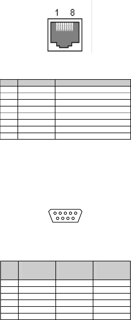
A 1.1. Ethernet Pin outs
The Pro Series uses a standard Ethernet connector, which is a shielded connector that is compliant
with the AT&T258 specifications. Table A-1 shows the pin assignment and wire color.
Figure A-1 Pin layout of the RJ45 connector
Table A-1 Pin assignment of the RJ45 connector for Ethernet
Pin Description Color
1 Tx+ White with orange
2 Tx- Orange
3 Rx+ White with green
4 NC Blue
5 NC White with blue
6 Rx- Green
7 NC White with brown
8 NC Brown
A 1.2. Console and Serial port pin-outs
The pin assignment of the PS110/PS410/PS810 DB9 connector is summarized in Table A-2. Each pin
has a function according to the serial communication type configuration.
6 7 8 9
1 2 3 4 5
Figure A-2 Pin layout of the DB-9 connector
Table A-2 Pin assignment of DB-9 connector for console and serial port
Pin RS232
(console and
serial ports)
RS422
(serial ports
only)
RS485
(serial ports
only)
1 DCD Tx+ Tx+
2 Rx RX+ RX+
3 Tx RTS+ -
4 DTR CTS+ -
5 GND GND GND
6 DSR TX- TX-
44
7 RTS RTS- -
8 CTS RX- RX-
9 - CTS- -
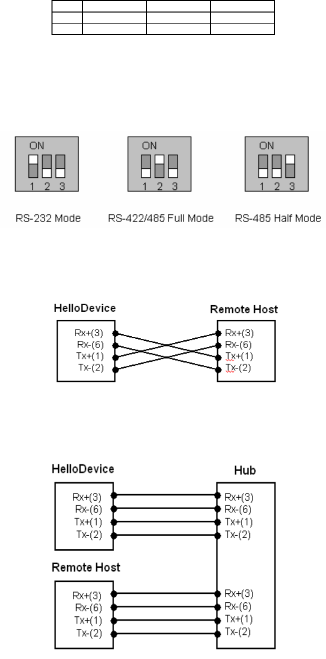
The serial communication type can be set by DIP switch near by serial port. (Only for PS110 and
PS410) To change the serial communication type, change the position of each DIP switch as shown
below. But please note that the power of the Pro Series should be turned off before changing the serial
communication type.
Figure A-3 Serial communication type and DIP switch configuration
A 1.3. Ethernet Wiring Diagram
Figure A-4 Ethernet direct connection using crossover Ethernet cable
Figure A-5 Ethernet connection using straight through Ethernet cable
45
Appendix 2. Parani-MSP1000 Configuration files
A 2.1. ip.conf

46
Appendix 3. Well-known port numbers
Port numbers are divided into three ranges: Well Known Ports, Registered Ports, and Dynamic and/or
Private Ports. Well Known Ports are those from 0 through 1023. Registered Ports are those from 1024
through 49151. Dynamic and/or Private Ports are those from 49152 through 65535.
Well Known Ports are assigned by IANA, and on most systems, can only be used by system
processes or by programs executed by privileged users. Table A-3 shows some of the well-known port
numbers. For more details, please visit the IANA website:
http://www.iana.org/assignments/port-numbers
Table A-3 Well-known port numbers
Port number Protocol TCP/UDP
21 FTP (File Transfer Protocol) TCP
22 SSH (Secure Shell) TCP
23 Telnet TCP
25 SMTP (Simple Mail Transfer Protocol) TCP
37 Time TCP, UDP
39 RLP (Resource Location Protocol) UDP
49 TACACS, TACACS+ UDP
53 DNS UDP
67 BOOTP server UDP
68 BOOTP client UDP
69 TFTP UDP
70 Gopher TCP
79 Finger TCP
80 HTTP TCP
110 POP3 TCP
119 NNTP (Network News Transfer Protocol) TCP
161/162 SNMP UDP
443 HTTPS TCP
47
Appendix 4. Guide to the Bios menu program
48
Appendix 5: Warranty
A.5.1. GENERAL WARRANTY POLICY
Sena Technologies, Inc. (hereinafter referred to as SENA) warrants that the Product shall conform to
and perform in accordance with published technical specifications and the accompanying written
materials, and shall be free of defects in materials and workmanship, for the period of time herein
indicated, such warranty period commencing upon receipt of the Product.
This warranty is limited to the repair and/or replacement, at SENA’s discretion, of defective or non-
conforming Product, and SENA shall not be responsible for the failure of the Product to perform
specified functions, or any other non- conformance caused by or attributable to: (a) any misapplication
or misuse of the Product; (b) failure of Customer to adhere to any of SENA’s specifications or
instructions; (c) neglect of, abuse of, or accident to, the Product; or (d) any associated or
complementary equipment or software not furnished by SENA.
Limited warranty service may be obtained by delivering the Product to SENA or to the international
distributor it was purchased through and providing proof of purchase or receipt date. Customer agrees
to insure the Product or assume the risk of loss or damage in transit, to prepay shipping charges to
SENA, and to use the original shipping container or equivalent.
A.5.2. LIMITATION OF LIABILITY
EXCEPT AS EXPRESSLY PROVIDED HEREIN, SENA MAKES NO WARRANTY OF ANY KIND,
EXPRESSED OR IMPLIED, WITH RESPECT TO ANY EQUIPMENT, PARTS OR SERVICES
PROVIDED PURSUANT TO THIS AGREEMENT, INCLUDING BUT NOT LIMITED TO THE IMPLIED
WARRANTIES OF MERCHANTABILITY AND FITNESS FOR A PARTICULAR PURPOSE. NEITHER
SENA NOR ITS DEALER SHALL BE LIABLE FOR ANY OTHER DAMAGES, INCLUDING BUT NOT
LIMITED TO DIRECT, INDIRECT, INCIDENTAL, SPECIAL OR CONSEQUENTIAL DAMAGES,
WHETHER IN AN ACTION IN CONTRACT OR TORT (INCLUDING NEGLIGENCE AND STRICT
LIABILITY), SUCH AS, BUT NOT LIMITED TO, LOSS OF ANTICIPATED PROFITS OR BENEFITS
RESULTING FROM, OR ARISING OUT OF, OR IN CONNECTION WITH THE USE OF FURNISHING
OF EQUIPMENT, PARTS OR SERVICES HEREUNDER OR THE PERFORMANCE, USE OR
INABILITY TO USE THE SAME, EVEN IF SENA OR ITS DEALER HAS BEEN ADVISED OF THE
POSSIBILITY OF SUCH DAMAGES. IN NO EVENT WILL SENA OR ITS DEALERS TOTAL LIABILITY
EXCEED THE PRICE PAID FOR THE PRODUCT.
A.5.3. HARDWARE PRODUCT WARRANTY DETAILS
WARRANTY PERIOD: SENA warranties embedded hardware Product for a period of one (1) year,
and external hardware Product for a period of three (3) or five (5) years according to the Product type.
WARRANTY PROCEDURE: Upon return of the hardware Product SENA will, at its option, repair or
replace Product at no additional charge, freight prepaid, except as set forth below. Repair parts and
replacement Product will be furnished on an exchange basis and will be either reconditioned or new.
All replaced Product and parts become the property of SENA. If SENA determines that the Product is
not under warranty, it will, at the Customers option, repair the Product using current SENA standard
rates for parts and labor, and return the Product at no charge in or out of warranty.
WARRANTY EXCLUSIONS: Damages caused by
- Accidents, falls, objects striking the SENA product,
- Operating the Product in environments that exceed SENA's temperature and humidity specifications,
- Power fluctuations, high voltage discharges,
- Improper grounding, incorrect cabling,
- Misuse, negligence by the customer or any other third party,
- Failure to install or operate the product (s) in accordance to their SENA User Manual,
- Failure caused by improper or inadequate maintenance by the customer or any other third party,
- Floods, lightning, earthquakes,
- Water spills,
- Replacement of parts due to normal wear and tear,
- Hardware has been altered in any way,
49
- Product that has been exposed to repair attempts by a third party without SENA’s written consent,
- Hardware hosting modified SENA Software, or non-SENA Software, unless modifications have been
approved by
SENA.
- Battery component capacity degradation due to usage, aging, and with some chemistry, lack of
maintenance.
A.5.4. SOFTWARE PRODUCT WARRANTY DETAILS
WARRANTY PERIOD: SENA warranties software Product for a period of one (1) year.
WARRANTY COVERAGE: SENA warranty will be limited to providing a software bug fix or a software
patch, at a reasonable time after the user notifies SENA of software non-conformance.
A.5.5. THIRD-PARTY SOFTWARE PRODUCT WARRANTY DETAILS
The warranty policy of the third-party software is conformed to the policy of the corresponding vendor