SENA TECHNOLOGIES PSX10W SERIAL DEVICE SERVER User Manual Manual PSx10W v1 0 1
Sena Technologies,Inc. SERIAL DEVICE SERVER Manual PSx10W v1 0 1
UserManual.wiki
>
SENA TECHNOLOGIES
>
PSX10W User Manual
USERS MANUAL
Navigation menu
Upload a User Manual
Namespaces
Wiki Guide
HTML
PDF
Info
Views
User Manual
Discussion / Help
Navigation
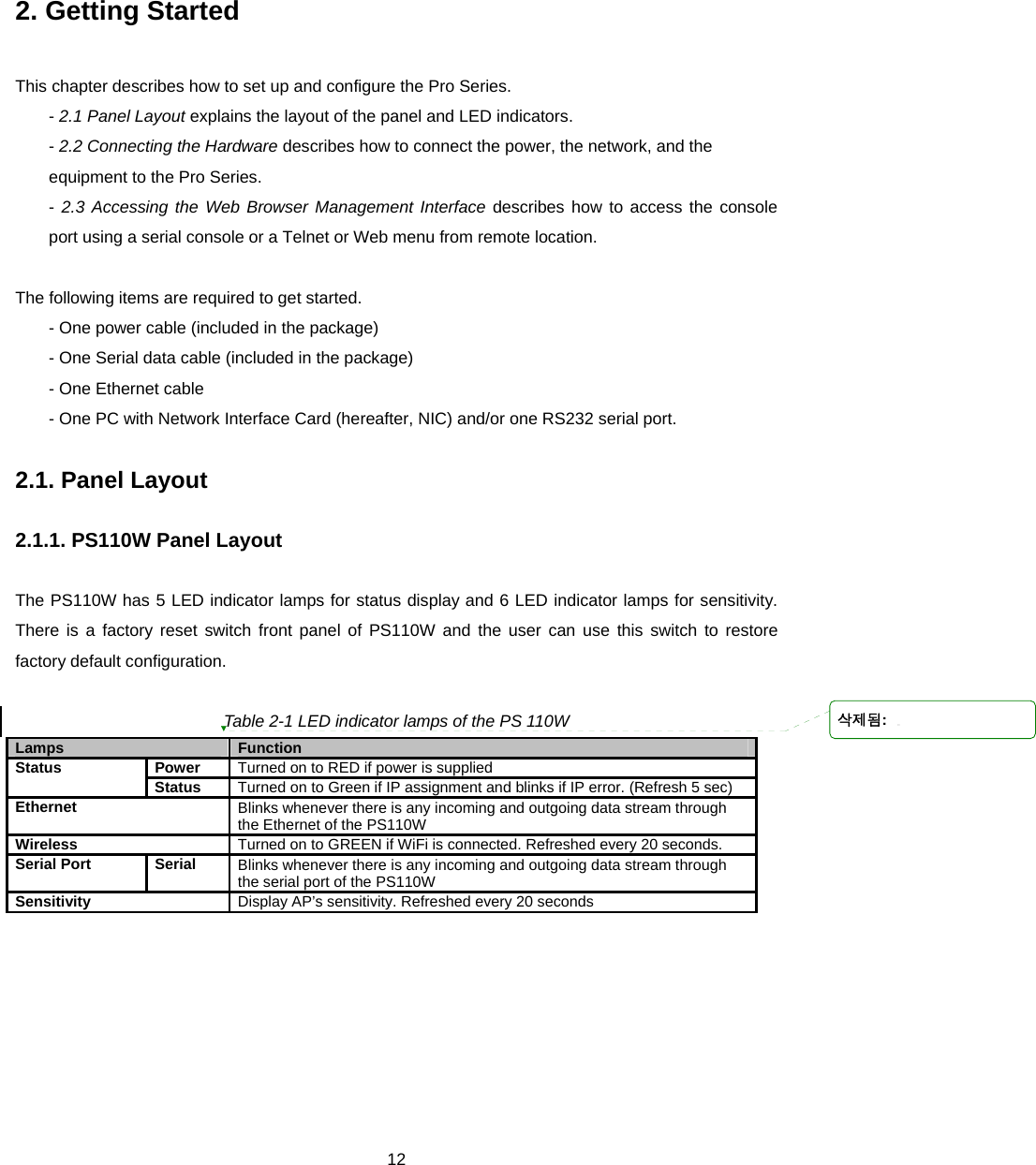
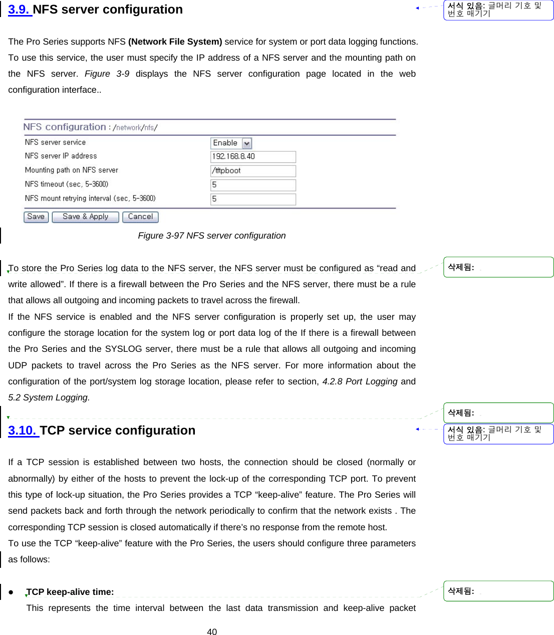
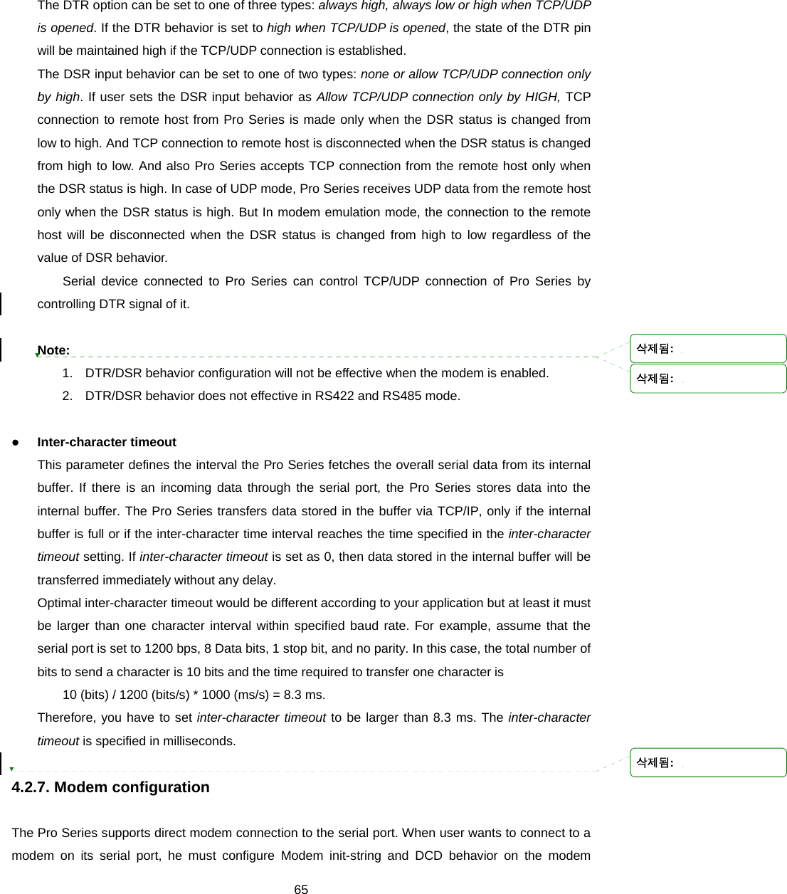
![Universal Device Servers HelloDevice Pro Series (PS110W/210W) User Guide Version 1.0.1 2007-12-21 메모 [..1]: 삭제됨: 1삭제됨: 2삭제됨: 0삭제됨: 0삭제됨: 1삭제됨: 2](https://usermanual.wiki/SENA-TECHNOLOGIES/PSX10W/User-Guide-888756-Page-1.png)

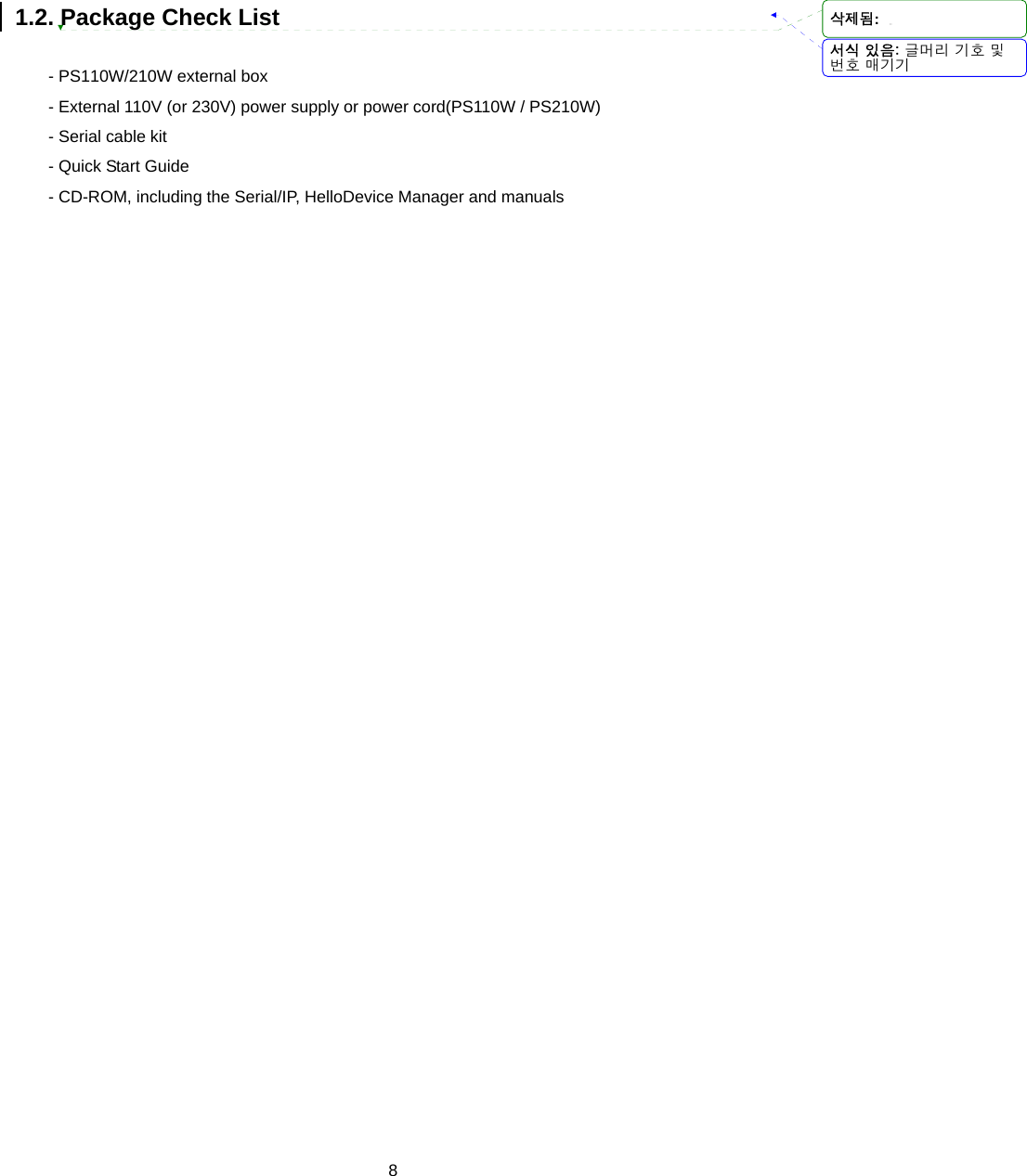

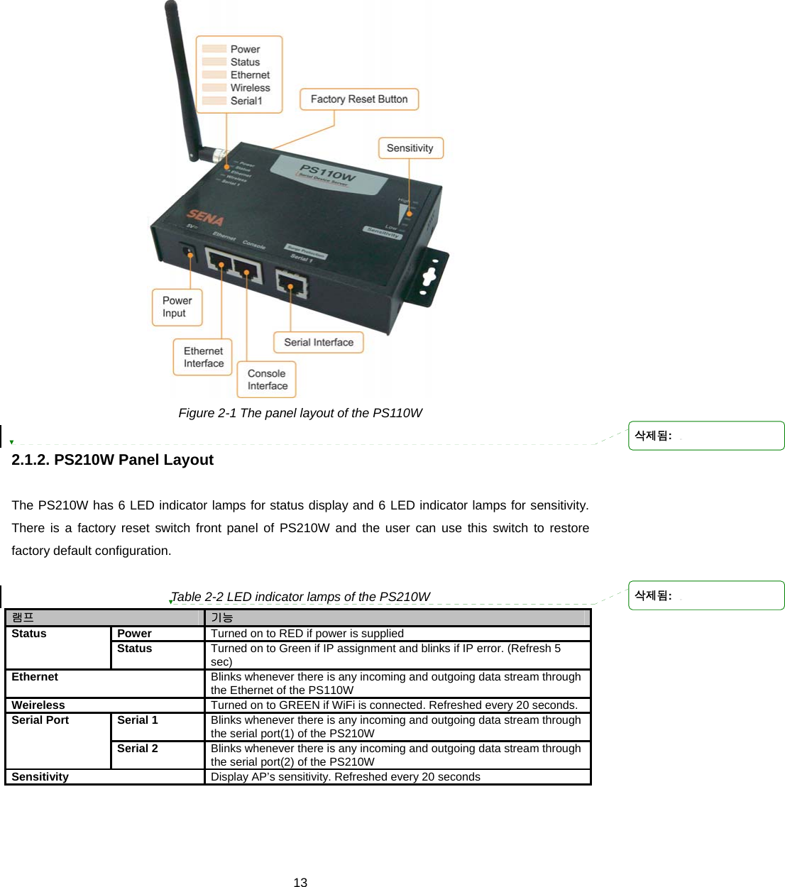
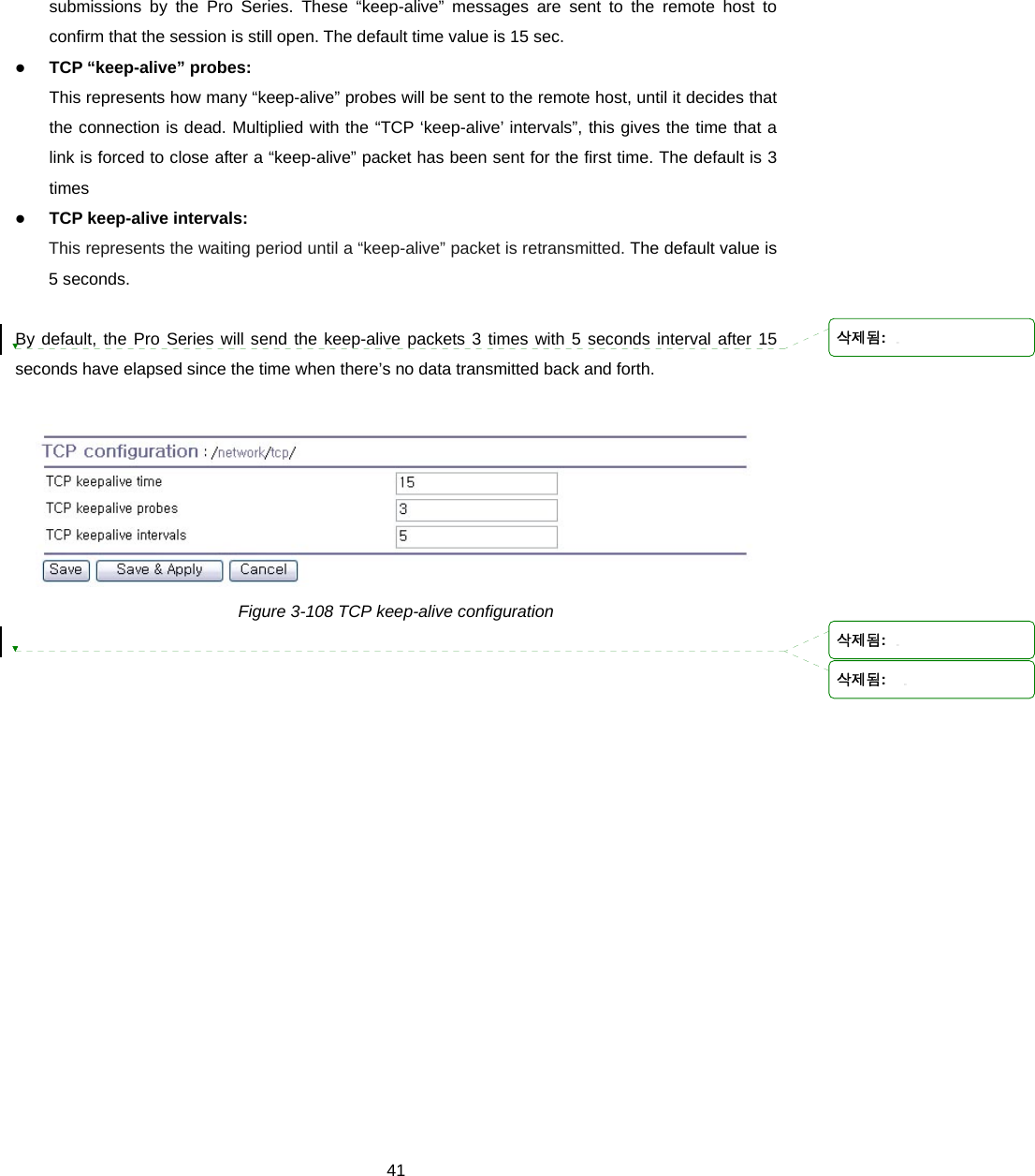
![14 Figure 2-2 The panel layout of the PS210W 2.2. Connecting the Hardware This section describes how to connect the Pro Series to your equipment for initial testing. - Connect the Pro Series to an Ethernet hub or switch - Connect the device - Connect the provided power source to the Pro Series 2.2.1. Connecting to the network Plug one end of the Ethernet cable to the Pro Series Ethernet port. The other end of the Ethernet cable should be connected to a network port. If the cable is properly connected, the Pro Series will have a valid connection to the Ethernet network. This will be indicated by: The [Ethernet] lamp will blink to indicate incoming/outgoing Ethernet packets 삭제됨:](https://usermanual.wiki/SENA-TECHNOLOGIES/PSX10W/User-Guide-888756-Page-14.png)
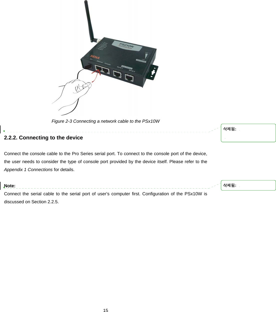
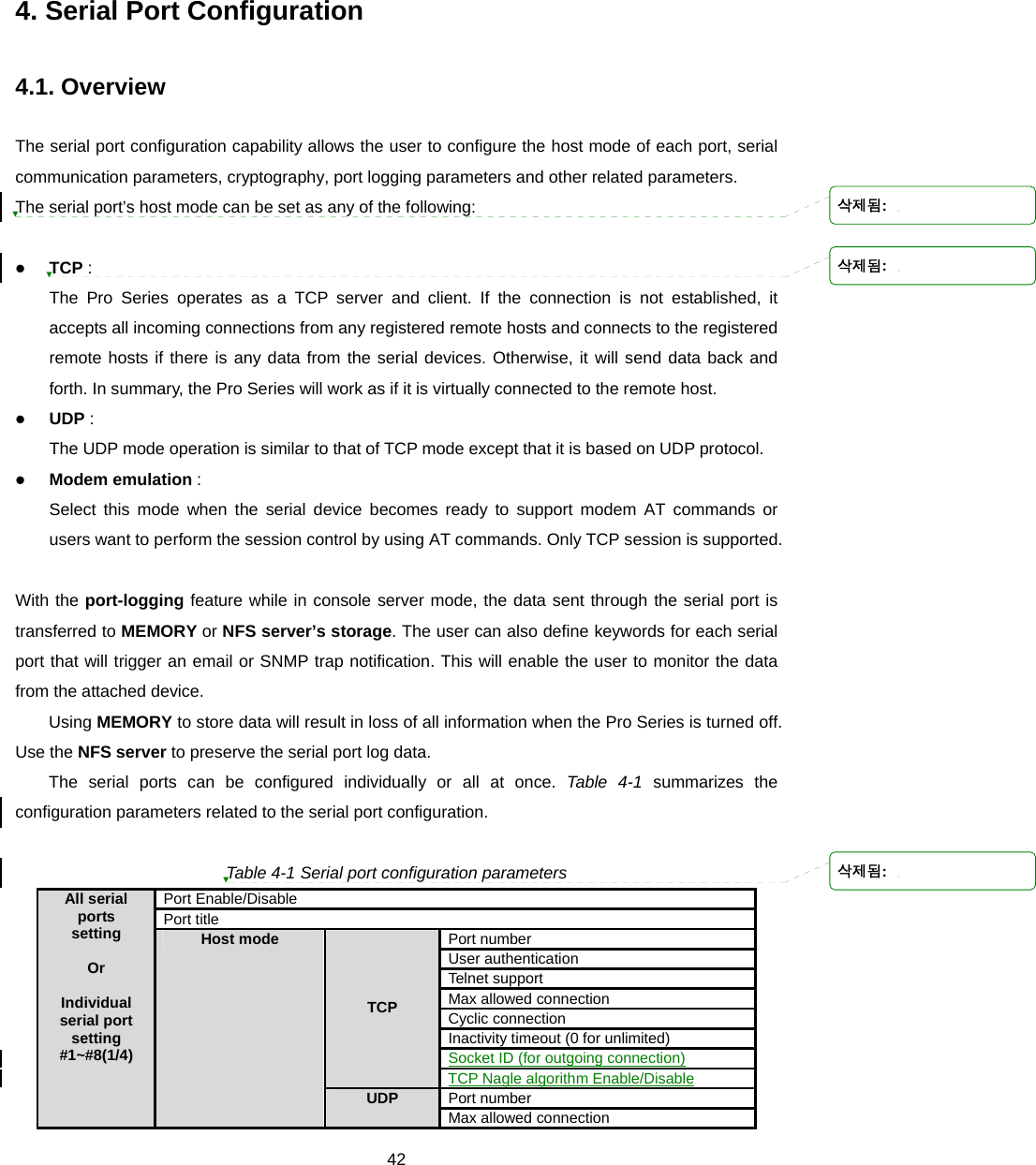
![16 Figure 2-4 Connecting a equipment to the PSx10W 2.2.3. Connecting the power Connect the power cable to the Pro Series. If the power is properly supplied, the [Power] lamp will light up solid red. Figure 2-5 Connecting the power to the PSx10W 2.2.4. Accessing the System Console There are several ways to access the Pro Series. These methods are dependent on whether the user is located at a local site or a remote site, or whether the user requires a menu-driven interface, graphic menu system or CLI (Command Line Interface). z System console: 삭제됨: 삭제됨:](https://usermanual.wiki/SENA-TECHNOLOGIES/PSX10W/User-Guide-888756-Page-16.png)
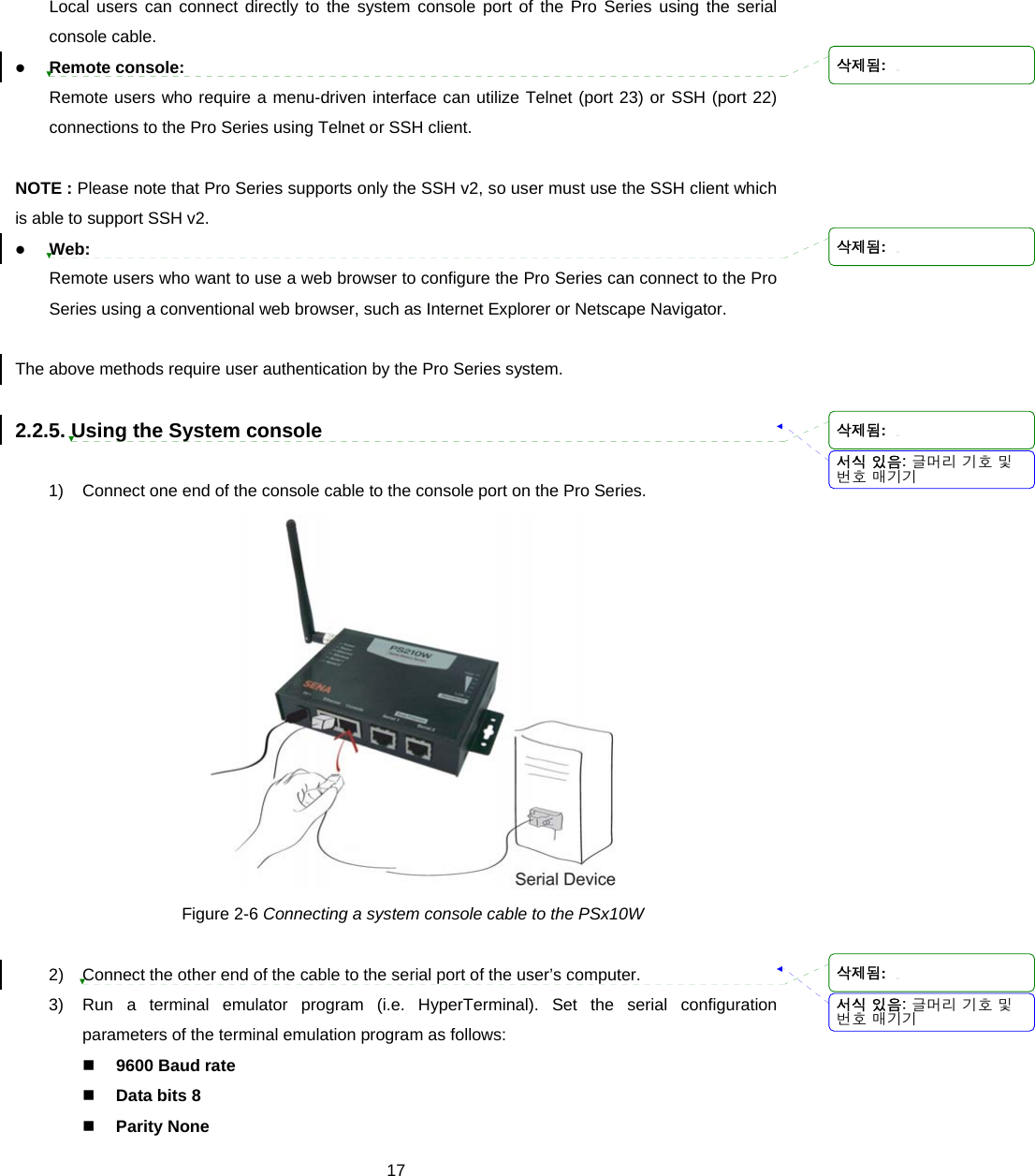
![18 Stop bits 1 No flow control 4) Press the [ENTER] key. 5) Enter your username and password to log into the Pro Series. The factory default user settings are as follows. Login: root Password: root ProSeries login: root Password: # 6) After login, user can use various shell commands in the CLI(Command Line interface). For details on the CLI, refer to the chapter 7 CLI guide. 7) “editconf” command will allow you to enter the text-menu driven interface and the menu screen in # editconf _] / [________________________________________________________________________ 1. Network configuration 2. Serial port configuration 3. System administration ________________________________________________________________________________ COMMAND (Display HELP : help)>save COMMAND (Display HELP : help)>apply COMMAND (Display HELP : help)>help _] HELP [_____________________________________________________________________ [Enter] refresh [ESC] cancel or go to upper / go to root .. go to upper clear clear screen pwd display path to current menu save save current configuration apply apply current configuration help display this exit exit ________________________________________________________________________________ COMMAND (Display HELP : help)>[Enter] _] / [________________________________________________________________________ 1. Network configuration 2. Serial port configuration 3. System administration ________________________________________________________________________________ COMMAND (Display HELP : help)> 8) Figure 2-7 is displayed. 서식 있음: 글머리 기호 및번호 매기기삭제됨: 삭제됨:](https://usermanual.wiki/SENA-TECHNOLOGIES/PSX10W/User-Guide-888756-Page-18.png)
![19 # editconf _] / [________________________________________________________________________ 1. Network configuration 2. Serial port configuration 3. System administration ________________________________________________________________________________ COMMAND (Display HELP : help)>save COMMAND (Display HELP : help)>apply COMMAND (Display HELP : help)>help _] HELP [_____________________________________________________________________ [Enter] refresh [ESC] cancel or go to upper / go to root .. go to upper clear clear screen pwd display path to current menu save save current configuration apply apply current configuration help display this exit exit ________________________________________________________________________________ COMMAND (Display HELP : help)>[Enter] _] / [________________________________________________________________________ 1. Network configuration 2. Serial port configuration 3. System administration ________________________________________________________________________________ COMMAND (Display HELP : help)> Figure 2-7 The main menu screen From the main menu screen, the users may select a menu item for configuration of the Pro Series parameters by selecting the menu number and pressing the [ENTER] key. In the submenu screen, users can configure the required parameters guided by online comments. All the parameters can be stored into the non-volatile memory space of the Pro Series, but the settings will not be stored until users enter ”save” command on the menu. All the configuration change will be effective after entering “apply” command on the menu. 2.2.6. Using Remote console The IP address of the Pro Series must be known before users can access the Pro Series using the Remote console (see chapter 3 Network Configuration for details). The default IP address of Pro Series is 192.168.161.5. The Remote console access function can be disabled in the remote host access option (3.6 IP Filtering for details). The following instructions will assist in setting up the Remote Console functionality: 서식 있음: 글머리 기호 및번호 매기기삭제됨: 삭제됨:](https://usermanual.wiki/SENA-TECHNOLOGIES/PSX10W/User-Guide-888756-Page-19.png)
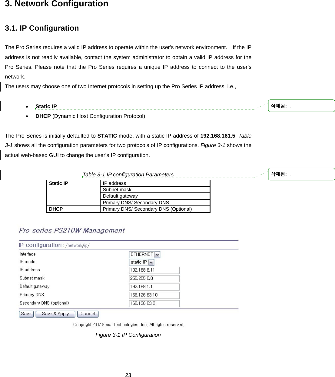
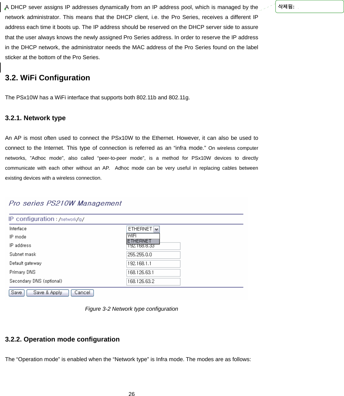
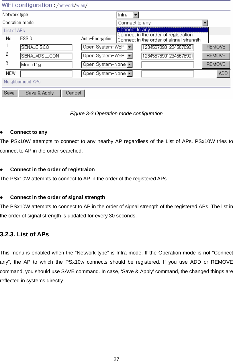
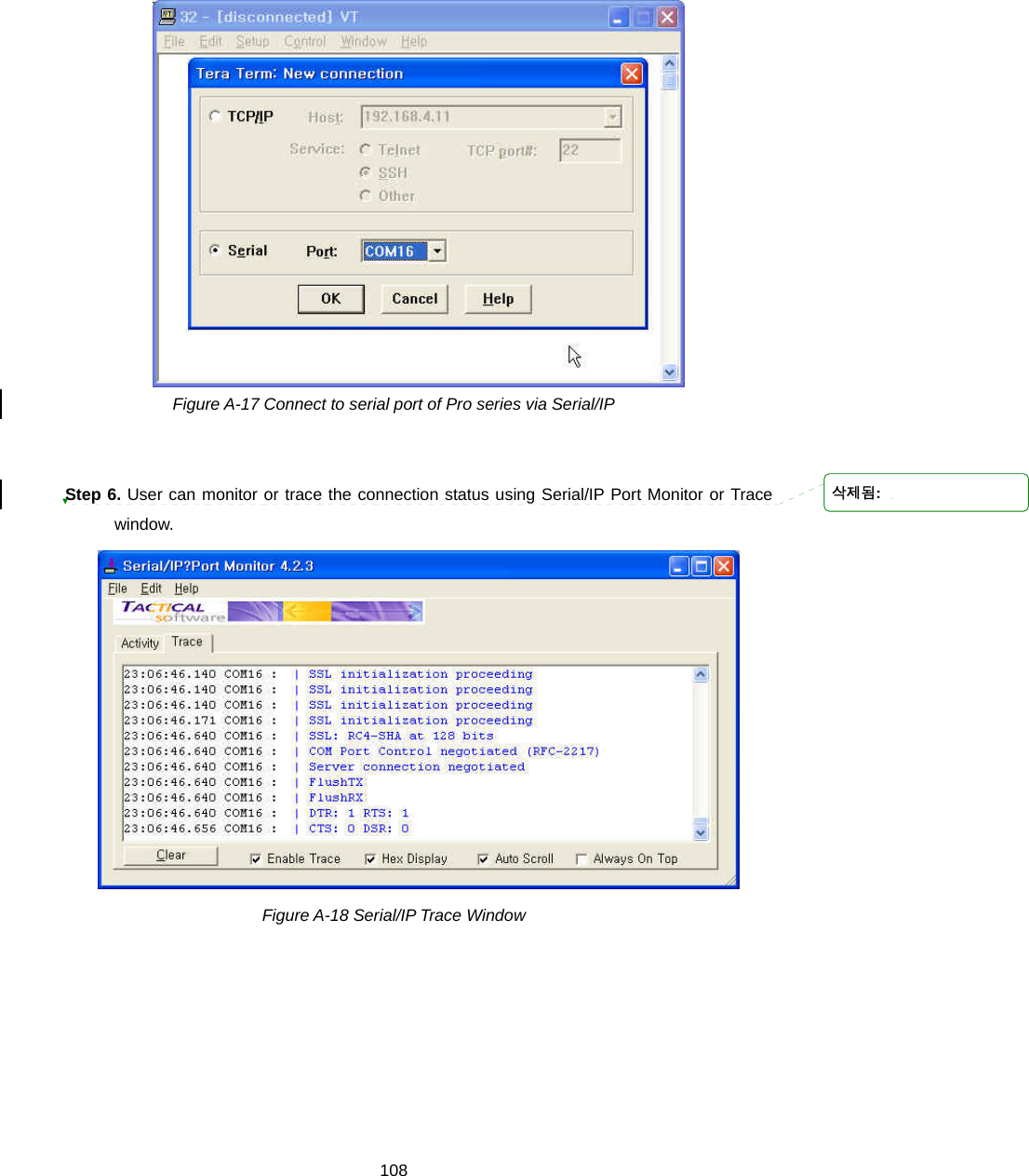
![201) ]Run either a Telnet program or a program that supports Telnet functions (i.e. TeraTerm-Pro or HyperTerminal). The target IP address and the port number must match the Pro Series. If required, specify the port number as 23. Type the following command in the command line interface of user’s computer. telnet 192.168.161.5 Or run a Telnet program with the following parameters: Figure 2-8 Telnet program set up example (TeraTerm Pro) 2) The user must log into the Pro Series. Type the user name and password. A factory default settings of the user name and password for CLI login are both root. 3) After entering correct user name and password, user can see the CLI prompts. 2.3. Accessing the Web Browser Management Interface The Pro Series supports both HTTP and HTTPS (HTTP over SSL) protocols. The Pro Series also contains its own Web management utility. To access the Pro Series Web management utility, enter the IP address or resolvable hostname of the Pro Series into the web browser’s URL/Location field. This will direct the user to the Pro Series login screen. The user must authenticate themselves by logging into they system with a correct user name and password. The factory default settings are: Login: root Password: root 삭제됨: 삭제됨: 삭제됨: 삭제됨:](https://usermanual.wiki/SENA-TECHNOLOGIES/PSX10W/User-Guide-888756-Page-20.png)
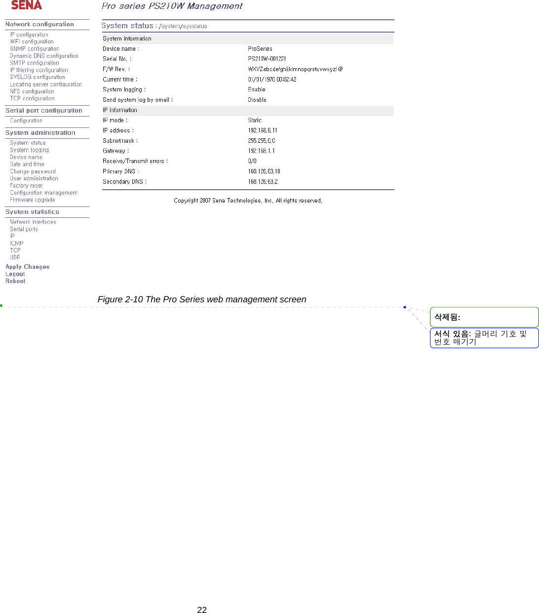
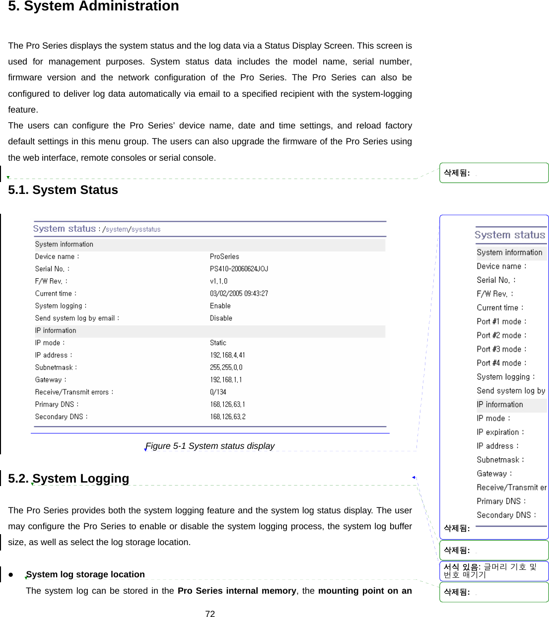
![21 Note: Before accessing the Pro Series Web management page, the user must check the IP address (or resolvable Hostname) of the Pro Series and Subnet mask settings. Figure 2-9 Login screen of the Pro Series web management Figure 2-10 shows the configuration homepage of the Pro Series Web management interface. A menu bar is provided on the left side of the screen. The menu bar includes the uppermost configuration menu groups. Selecting an item on the menu bar opens a tree view of all the submenus available under each grouping. Selecting a submenu item will allow the user to modify parameter settings for that item. Every page will allow the user to [Save], [Save & apply] or [Cancel] their actions. After changing the configuration parameter values, the users must select [Save] to save the changed parameter values to the non-volatile memory. To apply all changes made, the user must select [Apply Changes]. This option is available on the bottom of the menu bar. Only when the user selects [Apply changes] will the new parameter values be applied to the Pro Series configuration. The user also can select [Save & apply] to save parameters and apply changes in one step. If the user does not want to save the new parameter values, the user must opt to [Cancel]. All changes made will be lost and the previous values restored. But the changes that are already saved or applied cannot be canceled. 삭제됨: 삭제됨:](https://usermanual.wiki/SENA-TECHNOLOGIES/PSX10W/User-Guide-888756-Page-21.png)


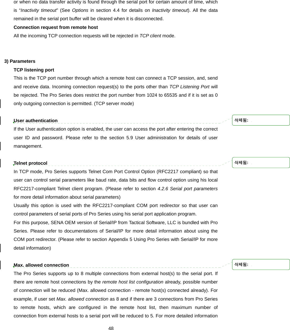
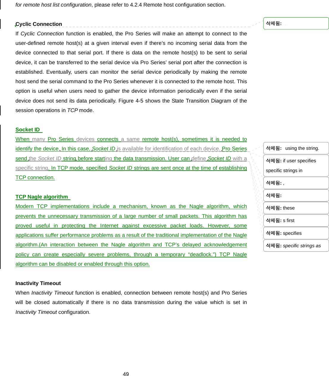
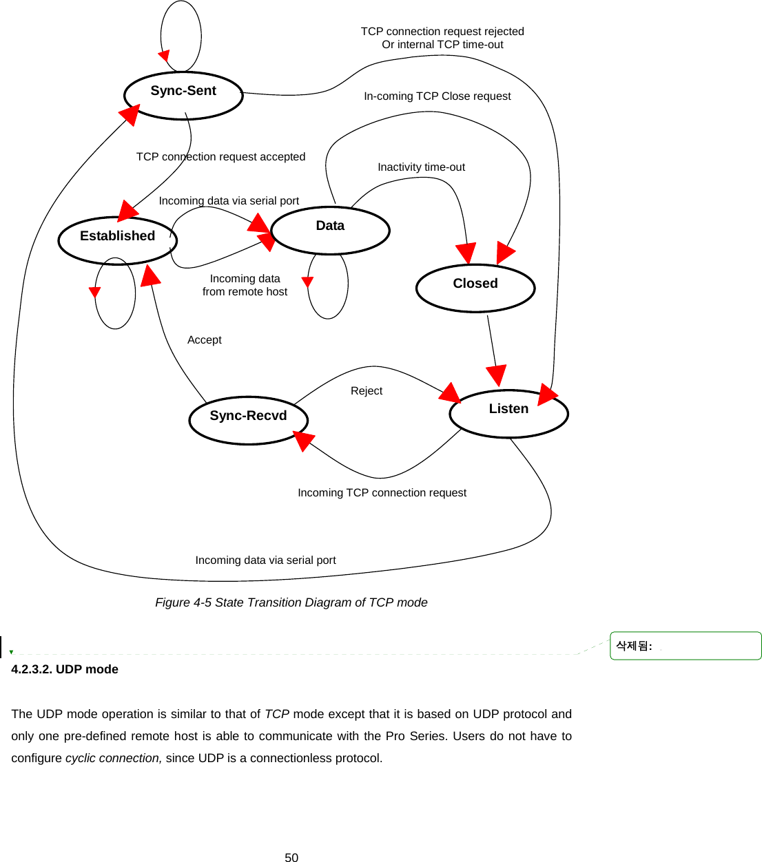
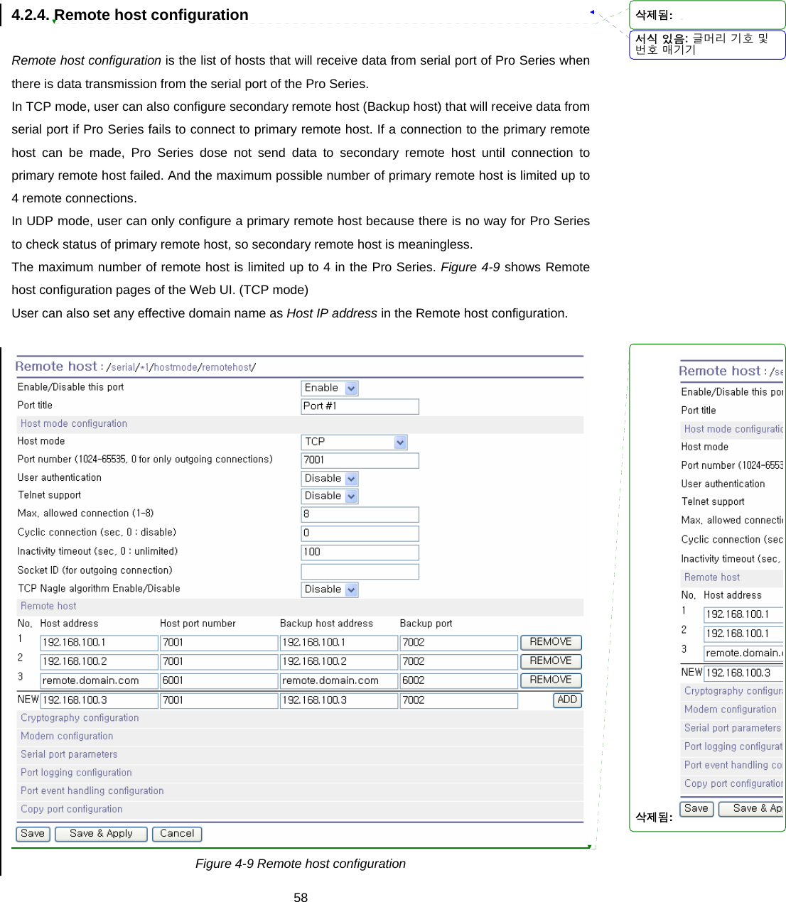
![46 Figure 4-4 Host mode configuration (TCP mode) 4.2.3.1. TCP mode For easier understanding of TCP modes, a simplified State Transition Diagram is often used. And to help users understand the diagram, the TCP state of the Pro Series is briefly described as follows. [Listen] It represents “a waiting for a connection request from any registered remote host”. It is a default start-up mode when it is set as TCP mode. [Closed] It means “no connection state”. If the data transfer between a remote host and the Pro Series is completed, the state is changed to this state as a result that either of the remote host or the Pro Series sent a disconnection request. After this, the state is automatically changed to [Listen] mode. [Sync-Received] The state is changed from [Listen] to [Sync-Received] if one of the remote hosts has sent a connection request. If the Pro Series accepts the request, the state is changed into [Established]. [Sync-Sent] If the Pro Series has sent a connection request to a remote host, the state is changed from [Closed] to [Sync-Sent]. This state is maintained until the remote host accepts the connection 서식 있음: 글머리 기호 및번호 매기기삭제됨: 삭제됨: 삭제됨:](https://usermanual.wiki/SENA-TECHNOLOGIES/PSX10W/User-Guide-888756-Page-46.png)
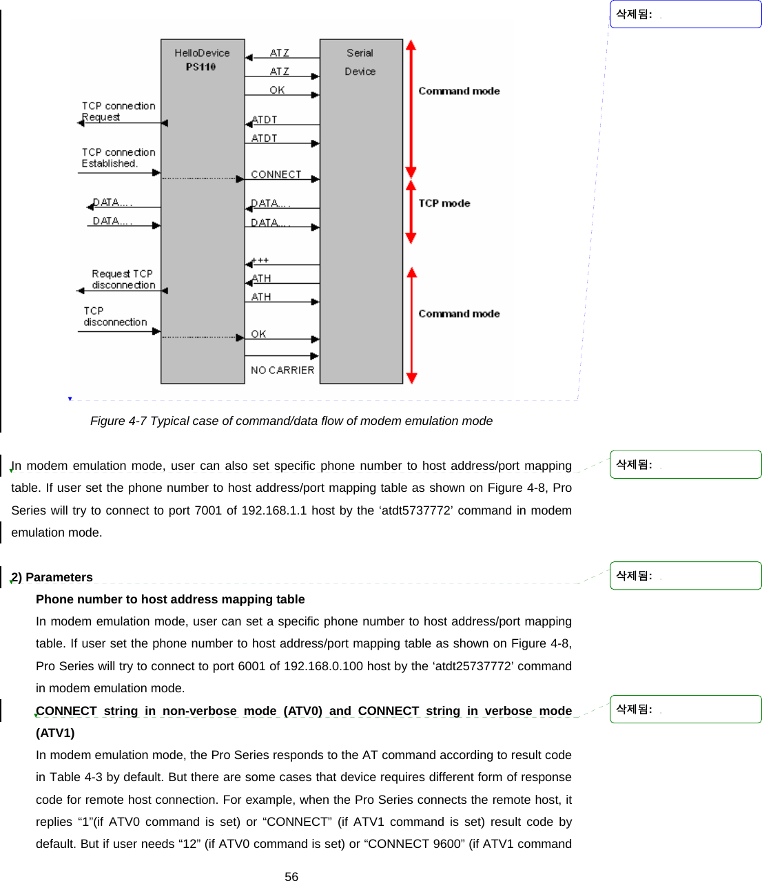
![47request. [Established] It represents “an open connection”. If one of the hosts, the remote host or the Pro Series, accepts a connection request from the other, the connection is opened and state is changed into [Established]. [Data] When it is in [Established] state, data from a host will be transferred to the other one. For easier understanding of the TCP session operation, we called the state as [Data] state when actual data transfer is performed. Actually, the [Data] mode is a part of [Established] state as is described in the RFC 793 [Transmission Control Protocol]. This is a normal state for the data transfer phase of the connection. The Pro Series works as either TCP server or client according to the situation. This will be the typical mode for most applications, since it will transfer the data either from serial port or from TCP port. The default TCP state is [Listen] which is the same as that of TCP server mode. 1) Typical State Transition [Listen] --> [Sync-Received] --> [Established] --> [Data] --> [Closed] --> [Listen] Or [Listen] --> [Sync-Sent] --> [Established] --> [Data] --> [Closed] --> [Listen] The initial state is [Listen]. If there are data coming from the serial port, it will connect to the remote host as a TCP client and then transfer data through the TCP port. If there is incoming connection request from the remote host, it will accept the connection as a TCP server, and then transfer data through the serial port. Thus, users can assume that the Pro Series is always connected to the specified remote host. 2) Operations Serial data transfer Whenever the serial device sends data through the serial port of the Pro Series, data will be accumulated on the serial port buffer of the Pro Series. If the buffer is full or the time gap reaches the inter-character timeout (See Options in section 4.4 for details on inter-character timeout), the Pro Series connect to the registered remote host(s). If a TCP session has not been established yet. If the Pro Series succeeds in connecting to the remote host, the data in the serial port buffer will be transferred to the host. Otherwise, all the data stored in the buffer will be cleared. Session disconnection The connected session will be disconnected when the remote host sends disconnection request 삭제됨: 삭제됨: 삭제됨:](https://usermanual.wiki/SENA-TECHNOLOGIES/PSX10W/User-Guide-888756-Page-47.png)
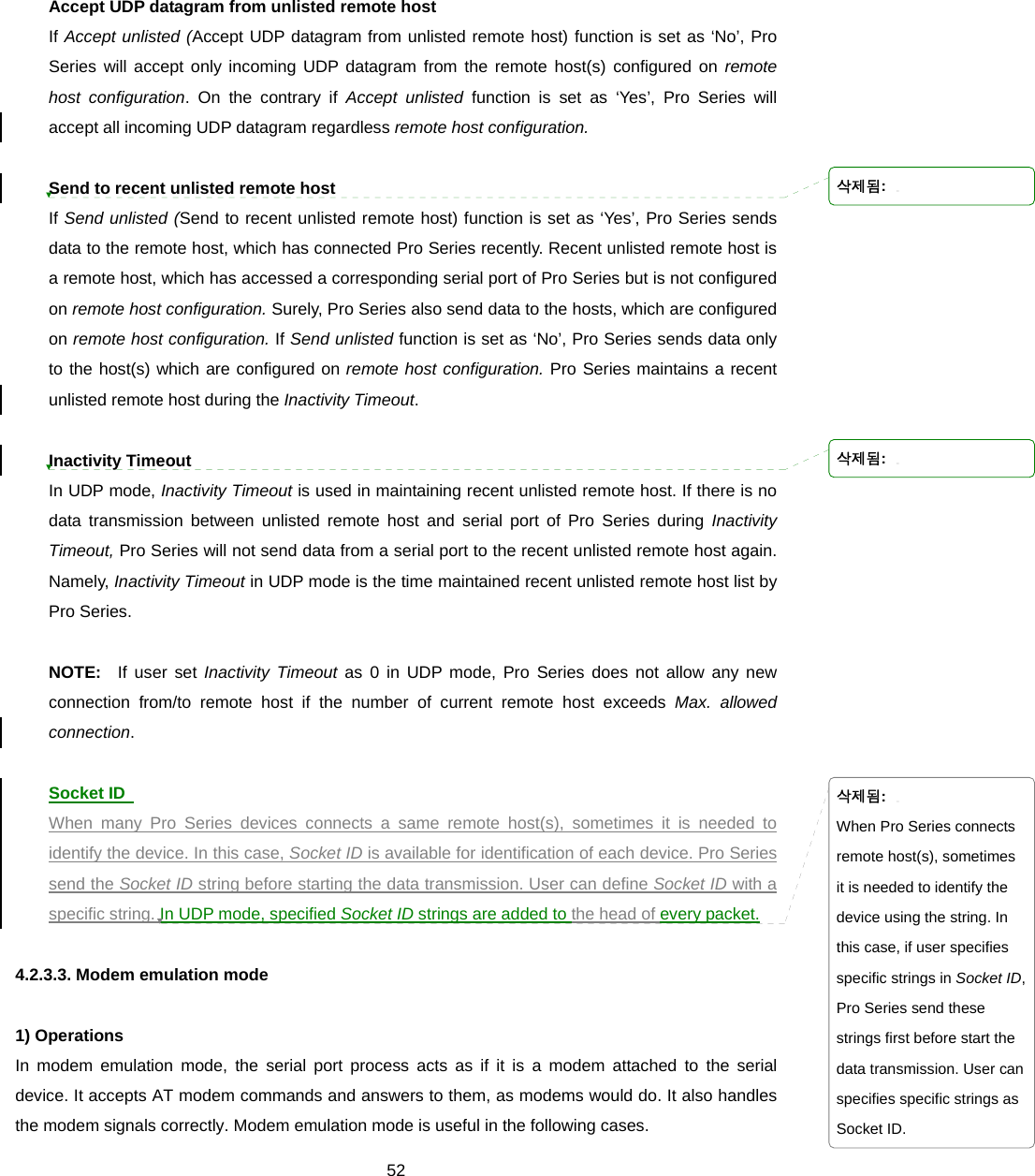
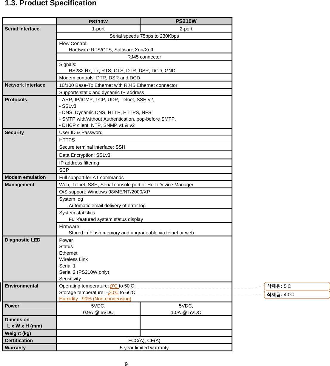
![53 There already exists a modem attached to the users’ serial device. If users’ serial device already has a modem for phone-line connection, it can be just replaced by the Pro Series for Ethernet connection. What users need to do is to use an IP address (or domain name) and port number instead of phone number as a parameter of ATA/ATDT commands. It is required to send serial data to the multiple remote hosts. If the serial device should send data to the multiple hosts, modem emulation mode is required. For example, the first data from the serial device can be sent to the first data acquisition server and the second to the second server. What user device has to do is to change the IP address (or domain name) and port number parameters whenever the device sends ATD(T) XXX command. By using the modem emulation mode of the Pro Series, users can have their serial device connected to the Ethernet network easily, which is cheaper than using phone line modem. Table 4-2 is a summarized AT command table which is supported by the Pro Series. Figure 4-7 shows the typical case of the serial port command flow when ATDA command is used to connect to the Ethernet network. Table 4-2 AT commands supported in the Pro Series Command Internal Operation Response 4 (Verbose Code) +++ Return to command input mode None ATD(T) [remote IP or domain name]:[remote port][CR][LF] or ATD(T) [remote IP][remote port] [CR][LF] Set TCP mode as TCP client mode. And then, try to connect to the specified remote host. e.g. atdt192.168.1.9:1002 e.g. atdt1921680010091002 Connect to IP address, 192.168.1.9, port 1002 (Port Number is permitted from 1 to 65534) e.g. atdtps.sena.com:1002 Connect to domain address ps.sena.com, port 1002 ATDR [remote IP or domain name]:[remote port] [CR][LF] This command is similar to ATD(T). The difference is that ATDR forces the connection to be Raw TCP connection regardless of Cryptography configuration and Default Data mode option. ATDS [remote IP or domain name]:[remote port] [CR][LF] This command is similar to ATD(T). The difference is that ATDR forces the connection to be SSLv3 connection. The Cryptography configuration should be SSLv3. If not, this command returns ERROR. If success, CONNECT [CR][LF] If failure in connection, NO CARRIER [CR][LF] If other errors, ERROR [CR][LF] 4 If Echo mode is enabled, the command will be sent back first. And then, corresponding response will be sent. If disabled, only response will be sent. 삭제됨: 삭제됨: 삭제됨: 과 기본적으로 동일합니다. 그러나 ATDR 명령은 Cryptography 설정과 Default Data mode 옵션과는 무관하게 Raw TCP mode로 접속을 시도합니다.삭제됨: ATD(T)과 기본적으로 동일 하지만, ATDS 명령은 SSLv3로 접속을 시도합니다. 단, Cryptography 설정이 SSLv3로 설정되었을시에만연결합니다..](https://usermanual.wiki/SENA-TECHNOLOGIES/PSX10W/User-Guide-888756-Page-53.png)
![54AT&Tn [CR][LF] Change and display the default data mode. AT&T : Display the current Default data mode AT&T0 : Change the Default data mode to Raw TCP mode AT&T1 : Change the Default data mode to Telnet binary modeAT&T If Data mode=RawTCP 0 [CR][LF] If Data mode=Telnet binary 1 [CR][LF] AT&Tn If success, OK[CR][LF] If failure, ERROR[CR][LF] AT or ATZ [CR][LF] Initialize TCP socket and serial port ATA/ [CR][LF] Repeat last command ATA [Local port number] [CR][LF] Set TCP mode as TCP server mode. And then, set TCP state as [Listen]. -. If the command parameter, Local port number is not specified, the TCP session parameter, Local Port is used instead. ATAR [Local port number] [CR][LF] This command is similar to ATA. The difference is that ATAR forces the connection to be Raw TCP connection regardless of Cryptography configuration and Default Data mode option.ATAS [Local port number] [CR][LF] This command is similar to ATA. The difference is that ATAS forces the connection to be SSLv3 connection. The Cryptography configuration should be SSLv3. If not, this command returns ERROR. ATEn [CR][LF] E, E0: Disable echo E1: Enable echo ATOn [CR][LF] O, O0: Turn to data mode ATQn [CR][LF] Q, Q0: Response display on (default) Q1: Response display off ATVn [CR][LF] V, V0: Response = <numeric code> [CR][LF] V1 (default): Response = <verbose code> [CR][LF] AT&Fn [CR][LF] F, F0, F1: Restore default modem settings ATHn [CR][LF] H, H0: Disconnect current TCP connection All the data will be cleared H1: Keep the current TCP connection If success, OK [CR][LF] If failure, ERROR [CR][LF] ATIn [CR][LF] I, I0 : display “Sena Technologies, Inc.” I3 : display model number Others : display “OK” <= AT\Tn [CR][LF] Set inactivity timer to n minutes \T, \T0: inactivity timer disabled (default) ERROR [CR][LF] or OK [CR][LF] ATBn, ATCn, ATLn, ATMn, ATNn, ATP, ATT, ATYn, AT%Cn, AT%En, AT&Bn, AT&Gn, AT&In, AT&Qn, AT&V, ATMn, AT\An, AT\Bn, AT\Nn, ATXn None OK [CR][LF] ATS?, ATSn=x Internal S-register can be set or read. Default values are shown on Table 4-4 Changed values are not preserved if the power is off. <= 삭제됨: Default data mode의 변경과 현재 설정된 Default data mode를 확인할수 있습니다.삭제됨: 현재삭제됨: e를 확인삭제됨: 를삭제됨: 로 변경삭제됨: 를삭제됨: 로 변경삭제됨: ATA명령과 기본적으로 동일 합니다. 그러나 ATAR 명령은 Cryptography 설정과 Default Data mode 옵션과는 무관하게 Raw TCP mode로 접속을 기다립니다..삭제됨: 삭제됨: ATA명령과 기본적으로 동일 하지만, ATAS 명령은 SSLv3로 접속을 기다립니다. 단, Cryptography 설정이 SSLv3로 설정되었을시에만연결합니다..삭제됨: If successful,OK [CR][LF]If failure,ERROR [CR][LF]삭제됨: }삭제됨: none삭제됨: , AT&Cn,AT&Wn, AT&Zn=x](https://usermanual.wiki/SENA-TECHNOLOGIES/PSX10W/User-Guide-888756-Page-54.png)
![55AT&Cn, AT&Wn, AT&Zn=x Factory default response is ERROR. This can be changed to OK by user configuration. (Figure 4-8) ERROR [CR][LF] or OK [CR][LF] ATFn [CR][LF] None If n=1 OK [CR][LF] Else ERROR [CR][LF] ATWn None If n=0 OK [CR][LF] Else ERROR [CR][LF] AT+DATE Set the system data and time e.g. AT+DATE=2007.01.01-14:30:30 AT+NET Set the IP address and the subnet mask. e.g. AT+NET= 192.168.17.9/255.255.0.0 AT+GATEWAY Set the default gateway e.g. AT+GATEWAY=192.168.1.1 AT+DNS Set the domain name server. e.g. AT+DNS=168.126.63.1/168.126.63.2 If success, OK [CR][LF] If failure, ERROR [CR][LF] Table 4-3 AT commands Response Code Verbose Code (After “ATV1” command executed) Non-Verbose Code(Numeric Code)(After “ATV0” command executed) Description OK 0 Command executed CONNECT 1 Modem connected to line RING 2 A ring signal has been detected NO CARRIER 3 Modem lost carrier signal ERROR 4 Invalid command Table 4-4 Default value of S-Registers Index Default Value Index Default Value Index Default Value 0 ~ 1 0 2 43 3 13 4 10 5 8 6 2 7 30 8 2 9 6 10 14 11 100 12 50 13 ~ 24 0 24 5 25 1 26 ~ 37 0 38 20 39 ~ 99 0 삭제됨: ERROR [CR][LF]삭제됨: 날짜와 시간을 변경합니다.삭제됨: 예)삭제됨: 2007년1월1일14시30분30초로 시간을 변경합니다.삭제됨: 와N삭제됨: 를 변경합니다.삭제됨: 예)삭제됨: 삭제됨: IP는192.168.17.9, Netmask는255.255.0.0으로 변경합니다.삭제됨: D삭제됨: 를 변경합니다.삭제됨: 예)삭제됨: Default gateway를192.168.1.1로 변경합니다.삭제됨: D삭제됨: N삭제됨: S삭제됨: 를 변경합니다삭제됨: 예삭제됨: )삭제됨: Domain Name Server를168.126.63.1, 168.126.63.2로 변경합니다.](https://usermanual.wiki/SENA-TECHNOLOGIES/PSX10W/User-Guide-888756-Page-55.png)
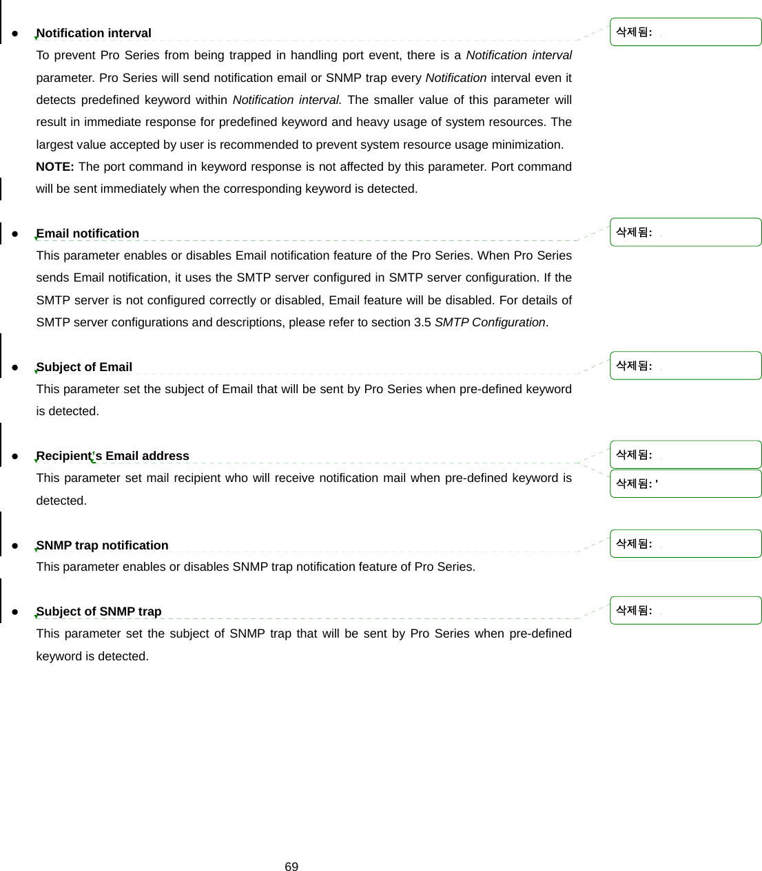
![57is set) response for this case, he can get the required result after setting CONNECT strings as shown on Figure 4-8. Respond to AT&Cn, AT&Wn and AT&Zn with For the following three AT commands, AT&Cn, AT&Wn, AT&Zn User can select the response as one of OK or ERROR. Command echo delay(ms) AT commands that are entered by user can be echoed with a delay specified in this menu. This is useful if user uses modem emulation mode in RS485 mode. Default command echo User can disable or enable echo of AT command that is entered by user in this menu. (Same functionality to ATEn command) Default data mode User can select the TCP data mode between Raw TCP mode and Telnet binary mode. The Raw TCP means that there is no application protocol over the TCP protocol. The Telnet binary mode means that there is Telnet protocol over the TCP protocol. The Telnet binary mode supports the Telnet COM Port Control Option defined by RFC2217. When selecting this option with a COM Port Redirector compatible with RFC2217, user is able to control the serial port parameter of the Pro Series through a serial port application such as Hyperterminal. Figure 4-8 Host mode configuration (Modem emulation mode) 삭제됨: 삭제됨: 삭제됨: TCP 연결이 이루어지고 나서 Data를 주고 받을 때, 어떤 형식으로 주고 받을지를 지정할수있습니다. Default data mode가 ‘Raw TCP’로 삭제됨: Default data mode가 ‘Telnet binary’로 지정되어 있을시에는, Modem emulation mode에서 텔넷 COM 포트 제어 옵션을 지원합니다. 대개 이 옵션은 삭제됨: 삭제됨: ... [2]... [1]](https://usermanual.wiki/SENA-TECHNOLOGIES/PSX10W/User-Guide-888756-Page-57.png)

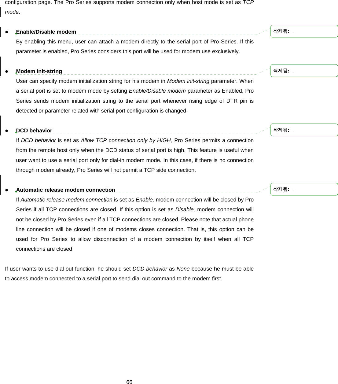
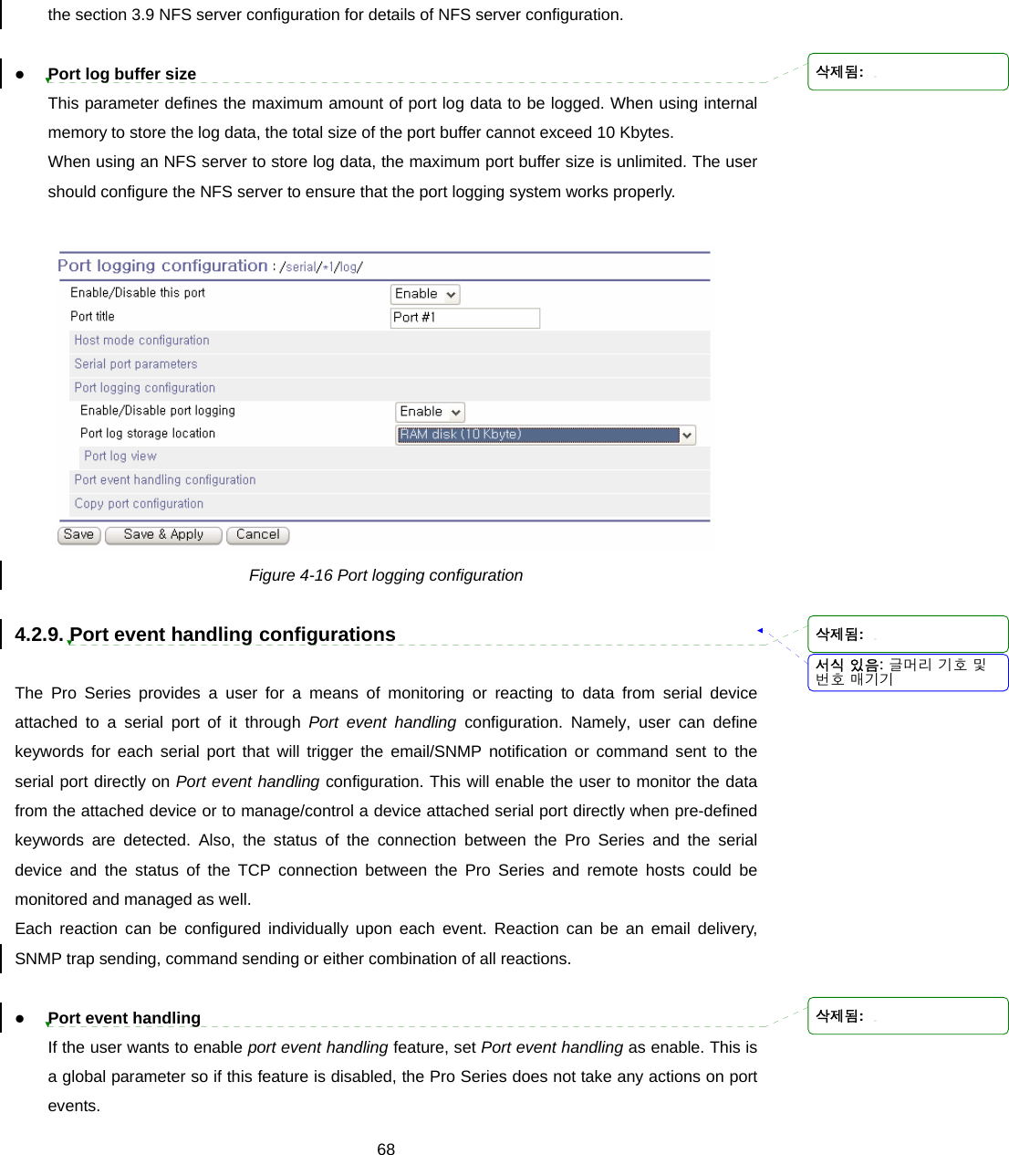
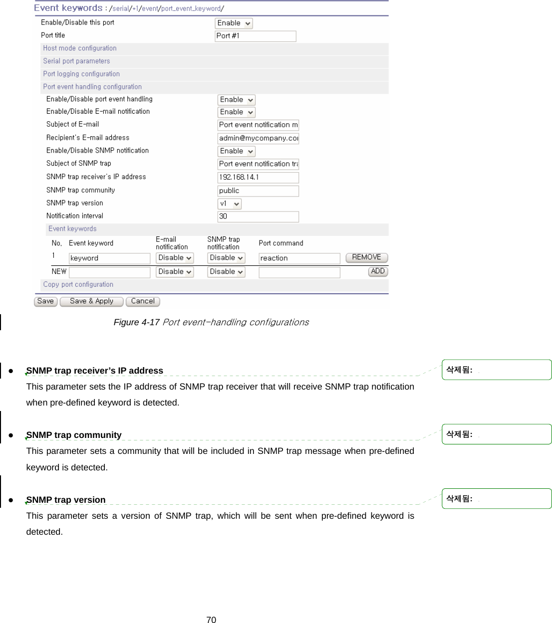
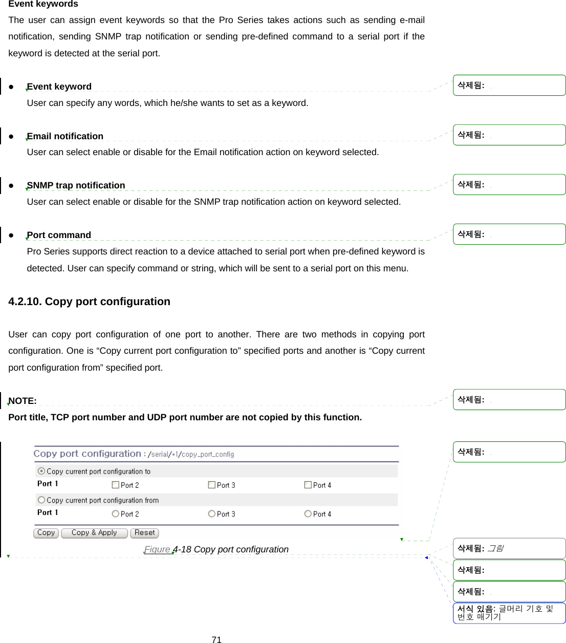
![67 Figure 4-15 Modem configuration 4.2.8. Port Logging With the port logging feature, the data sent through the serial port is stored to MEMORY or a mounting point on an NFS server. z Enable/disable port logging This parameter defines whether to enable or disable the port-logging feature. The factory default setting is [disabled]. z Port log storage location The port log data can be stored to the Pro Series’ internal memory or the mounting point on an NFS server. If the internal memory is used to store port log data, the port log data will be cleared when the Pro Series is turned off. To preserve the serial port log data, set the storage location to be the NFS server. To do this, the user must configure the NFS server in advance. Please refer to 서식 있음: 글머리 기호 및번호 매기기삭제됨: 삭제됨: 삭제됨: 삭제됨:](https://usermanual.wiki/SENA-TECHNOLOGIES/PSX10W/User-Guide-888756-Page-67.png)

![76 Figure 5-8 Configuration Management To export the current configurations, follow this: 1. Select the encrypting option 2. Type the file name. 3. Click the [Export] button. To import the exported configurations, follow this: 1. Select the location to import from. 2. Select the configurations to import. 3. Select the encrypting option. 4. Select the file to import from the file selection list box if location is not local machine nor factory default. 5. Select the file to import by clicking browse button if location is local machine. 6. Click the [Import] button. 서식 있음: 글머리 기호 및번호 매기기서식 있음: 글머리 기호 및번호 매기기](https://usermanual.wiki/SENA-TECHNOLOGIES/PSX10W/User-Guide-888756-Page-76.png)
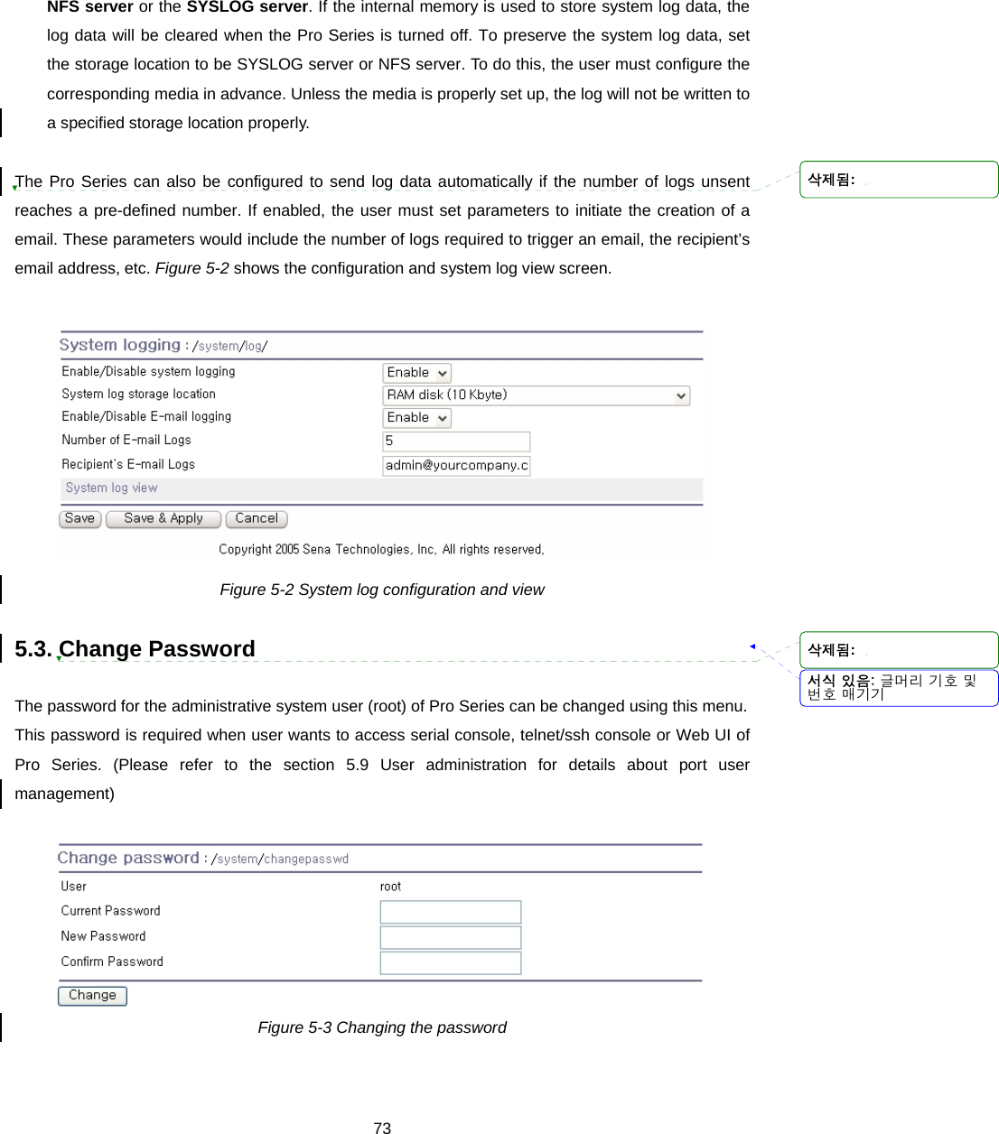
![77 5.8. Firmware Upgrade Firmware upgrades are available via serial, remote console or web interface. The latest upgrades are available on the Sena web site at http://www.sena.com/support/downloads/. Figure 5-9 shows the firmware upgrade web interface. To upgrade firmware via the web: 1. Select the latest firmware binary by clicking browse button. 2. Select and upload the selected version. 3. Once the upgrade has been completed, the system will reboot to apply the changes. Figure 5-9 Firmware upgrade To use either a remote or serial console to upgrade your firmware, the TELENT/SSH or terminal emulation program must support Zmodem transfer protocol. The previous settings will be retained after the firmware upgrade. To upgrade firmware via a remote console: 1. Obtain the latest firmware. 2. Connect the terminal emulation program using either TELENT/SSH or a serial console port. (TELNET or SSH is recommended since the process of firmware upgrade by serial console requires extremely long time.) 3. Select from the firmware upgrade menu as shown in login: root Password: # editconf _] / [________________________________________________________________________ 1. Network configuration 2. Serial port configuration 3. System administration ________________________________________________________________________________ COMMAND (Display HELP : help)>3 서식 있음: 글머리 기호 및번호 매기기삭제됨: 삭제됨: 삭제됨: 삭제됨: 삭제됨:](https://usermanual.wiki/SENA-TECHNOLOGIES/PSX10W/User-Guide-888756-Page-77.png)
![78_] System administration [____________________________________________________ 1. System status 2. System logging 3. Device Name : PSx10W 4. Date and time 5. Change password 6. User Administration 7. Factory reset 8. Firmware upgrade ________________________________________________________________________________ COMMAND (Display HELP : help)>8 _] Firmware upgrade [_________________________________________________________ Do you want to upgrade firmware? [yes/no] yes Transfer firmware by zmodem using your terminal application. To escape, press Ctrl+X **B0ff000005b157 4. Figure 5-10 5. Follow the online directions and transfer the firmware binary file using the Zmodem protocol as shown in Figure 5-11. 6. Once the upgrade has been completed, the system will reboot to apply the changes 7. If the firmware upgrade fails, the Pro Series will display error messages as shown in Figure 5-12. It will also maintain the current firmware version. 서식 있음: 글머리 기호 및번호 매기기서식 있음: 글머리 기호 및번호 매기기](https://usermanual.wiki/SENA-TECHNOLOGIES/PSX10W/User-Guide-888756-Page-78.png)
![79 login: root Password: # editconf _] / [________________________________________________________________________ 1. Network configuration 2. Serial port configuration 3. System administration ________________________________________________________________________________ COMMAND (Display HELP : help)>3 _] System administration [____________________________________________________ 1. System status 2. System logging 3. Device Name : PSx10W 4. Date and time 5. Change password 6. User Administration 7. Factory reset 8. Firmware upgrade ________________________________________________________________________________ COMMAND (Display HELP : help)>8 _] Firmware upgrade [_________________________________________________________ Do you want to upgrade firmware? [yes/no] yes Transfer firmware by zmodem using your terminal application. To escape, press Ctrl+X **B0ff000005b157 Figure 5-10 Firmware upgrade using remote/serial console Figure 5-11 Transfer binary file by Zmodem (TeraTerm Pro) 서식 있음: 글머리 기호 및번호 매기기삭제됨: 삭제됨: 삭제됨: Follow the online directions and transfer the firmware binary file using the Zmodem protocol as shown in Figure 5-10Figure 5-10Figure 5-10Figure 5-10Figure 5-10Figure 5-10Figure 5-10.Once the upgrade has been completed, the system will reboot to apply the changesIf the firmware upgrade fails,the Pro Series will display error messages as shown in Figure 5-11Figure 5-11Figure 5-11Figure 5-11Figure 5-11Figure 5-11Figure 5-11. It will also maintain the current firmware version.](https://usermanual.wiki/SENA-TECHNOLOGIES/PSX10W/User-Guide-888756-Page-79.png)
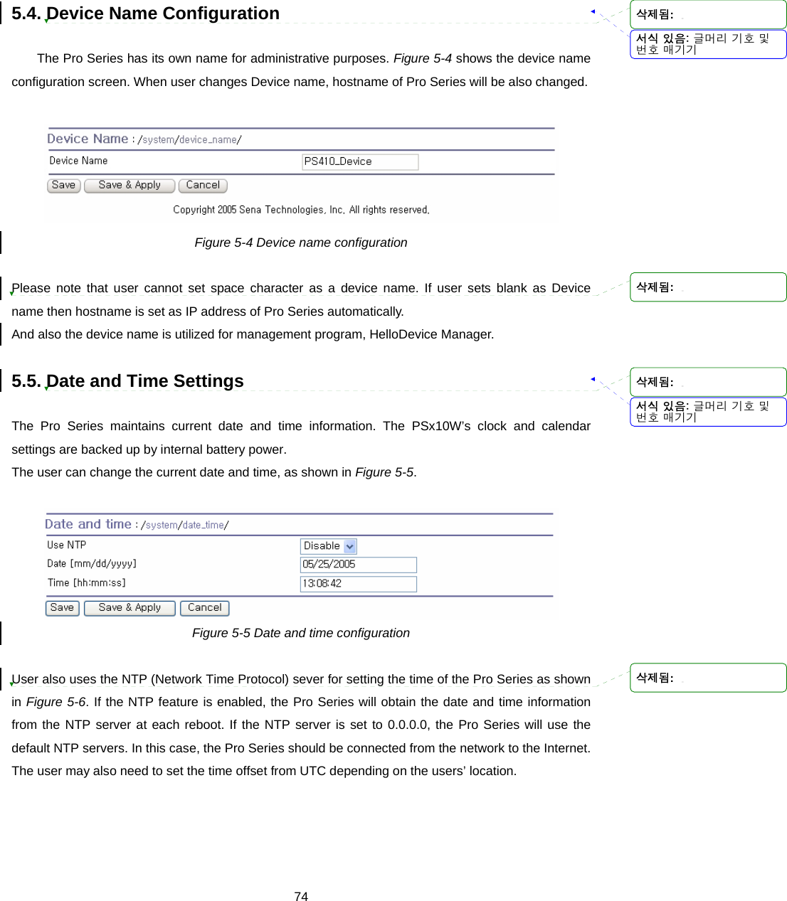
![80 _] Firmware upgrade [_________________________________________________________ Do you want to upgrade firmware? [yes/no] yes Transfer firmware by zmodem using your terminal application. To escape, press Ctrl+X **B0ff000005b157 **B0ff000005b157 **B0ff000005b157 **B0ff000005b157 Firmware upgrade failed ! Now reboot ... Figure 5-12 Firmware upgrade failure message 5.9. User administration User can enable port authentication (see section 4.2.3.1 TCP mode), then user should enter correct user ID and password of each port when he tries to access the serial port. The user ID and password for each serial port can be set using this menu. When user adds a new user for serial port, he can also assign permissible serial ports to the user selectively, as shown on Figure 5-13 Port user administration. Figure 5-13 Port user administration NOTE: System user (root) cannot access serial ports unless he is also added as a port user in this menu. To set the password for the port user or to change the configuration of each port user, click the corresponding number associated with the port user on port user administration page, then port user configuration page will be displayed as shown on Figure 5-14 Port user configuration. 서식 있음: 글머리 기호 및번호 매기기삭제됨: 삭제됨: 삭제됨: 삭제됨:](https://usermanual.wiki/SENA-TECHNOLOGIES/PSX10W/User-Guide-888756-Page-80.png)


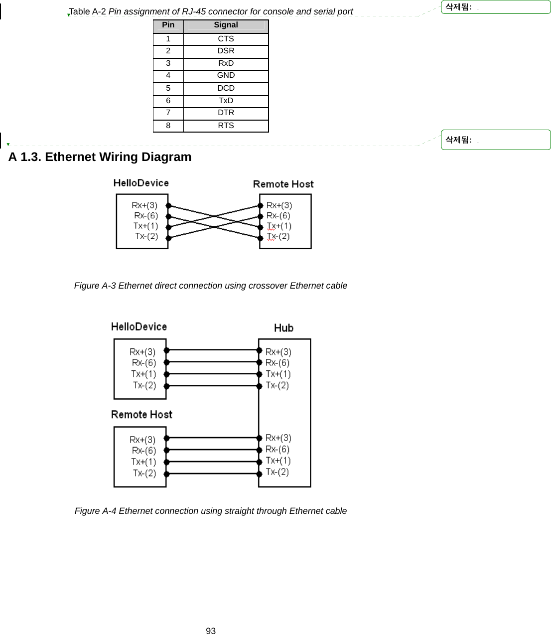
![917.4. Accessing CLI Serial console: 1) ]Connect the console port of the Pro Series with the PC serial port 2) Run a PC terminal emulation program 3) Configure the PC serial port to: 9600-8-N-1 No flow control 4) Press <enter> 5) Login with the Pro Series root account Telnet console: 1) telnet Pro_Series_ip_address SSH console: 1) ssh -2 Pro_Series_ip_address NOTE : The Pro Series support only SSH v2 protocol. 삭제됨:](https://usermanual.wiki/SENA-TECHNOLOGIES/PSX10W/User-Guide-888756-Page-91.png)


![98Appendix 4. Guide to the Bios menu program A 4.1. Overview The bios menu provides a way to recover the Pro Series unit, by using TFTP, as a disaster recovery option and to diagnose the system hardware. If the user presses the <ESC> key within 3 seconds after the Pro Series unit is powered up, the user will enter the bios menu program. From this menu program, the user can set various system parameters, test system hardware, and perform firmware upgrades. A 4.2. Main menu After entering the bios menu program, the user will see following main menu page: ----------------------------------------------------------------------------- BIOS v1.0.0 (c) 1998-2005 Sena Technologies, Inc. ----------------------------------------------------------------------------- ----------------------------------------------------------------------------- Welcome to Boot Loader Configuration page ----------------------------------------------------------------------------- Select menu 1. RTC Configuration 2. Hardware test 3. Firmware upgrade [S/W Version : v1.0.0] 4. Exit and boot from flash 5. Exit and reboot <ESC> Back, <ENTER> Refresh -----> Figure A-6 Main Menu Page of Bios Menu A 4.3. RTC configuration menu Using the RTC configuration menu, the user can set the system time of the Pro Series. 서식 있음: 글머리 기호 및번호 매기기서식 있음: 글머리 기호 및번호 매기기서식 있음: 글머리 기호 및번호 매기기삭제됨: 삭제됨: 삭제됨: 삭제됨: 삭제됨:](https://usermanual.wiki/SENA-TECHNOLOGIES/PSX10W/User-Guide-888756-Page-98.png)
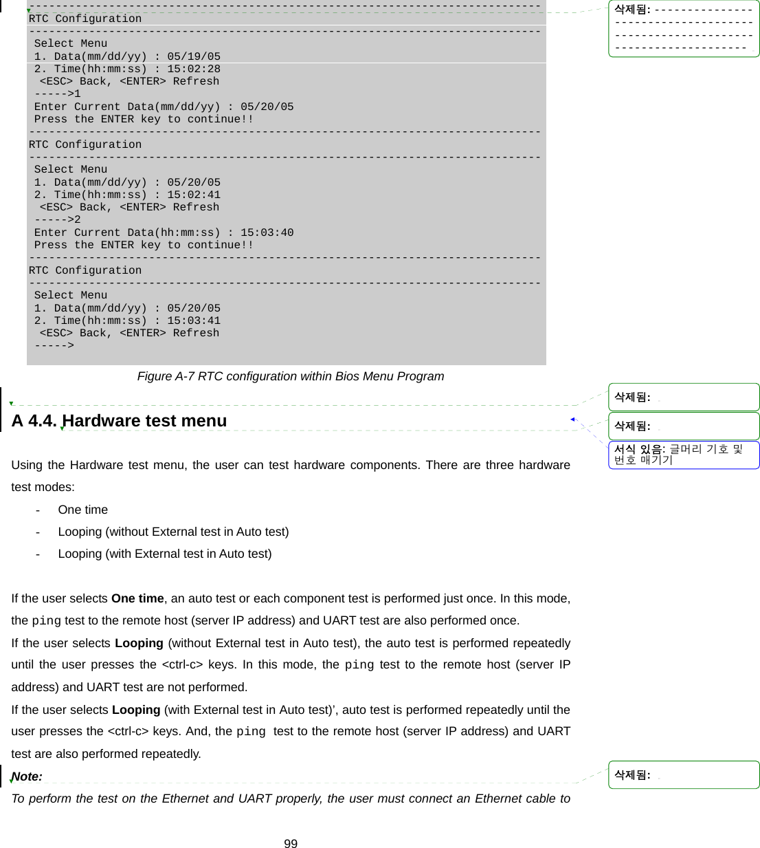
![100the Ethernet port of the Pro Series and must plug the loopback connector to all the serial ports of the Pro Series. There must exist a remote host with a valid IP address. The default server IP address is 192.168.0.128 and it can be changed using the [Firmware Upgrade] menu. Otherwise, the test may not be performed properly. ----------------------------------------------------------------------------- Hardware Test ----------------------------------------------------------------------------- Select menu 0. Test Mode - One Time 1. Auto test 2. DRAM test 3. FLASH test 4. EEPROM test 5. Ethernet test 6. UART Mode test <ESC> Back, <ENTER> Refresh -----> 0 ----------------------------------------------------------------------------- Hardware Test ----------------------------------------------------------------------------- Select menu 0. Test Mode - Looping(Without External test in Auto Test) 1. Auto test 2. DRAM test 3. FLASH test 4. EEPROM test 5. Ethernet test 6. UART Mode test <ESC> Back, <ENTER> Refresh -----> 0 ----------------------------------------------------------------------------- Hardware Test ----------------------------------------------------------------------------- Select menu 0. Test Mode - Looping(With External test in Auto Test) 1. Auto test 2. DRAM test 3. FLASH test 4. EEPROM test 5. Ethernet test 6. UART Mode test <ESC> Back, <ENTER> Refresh -----> 0 ----------------------------------------------------------------------------- Hardware Test ----------------------------------------------------------------------------- Select menu 0. Test Mode - One Time 1. Auto test 2. DRAM test 3. FLASH test 4. EEPROM test 5. Ethernet test 6. UART Mode test <ESC> Back, <ENTER> Refresh -----> Figure A-8 Hardware test menu within Bios Menu Program When the user selects [Auto test], a test of all the hardware components is performed automatically. 삭제됨: 삭제됨: -----------------------------------------------------------------------------삭제됨:](https://usermanual.wiki/SENA-TECHNOLOGIES/PSX10W/User-Guide-888756-Page-100.png)
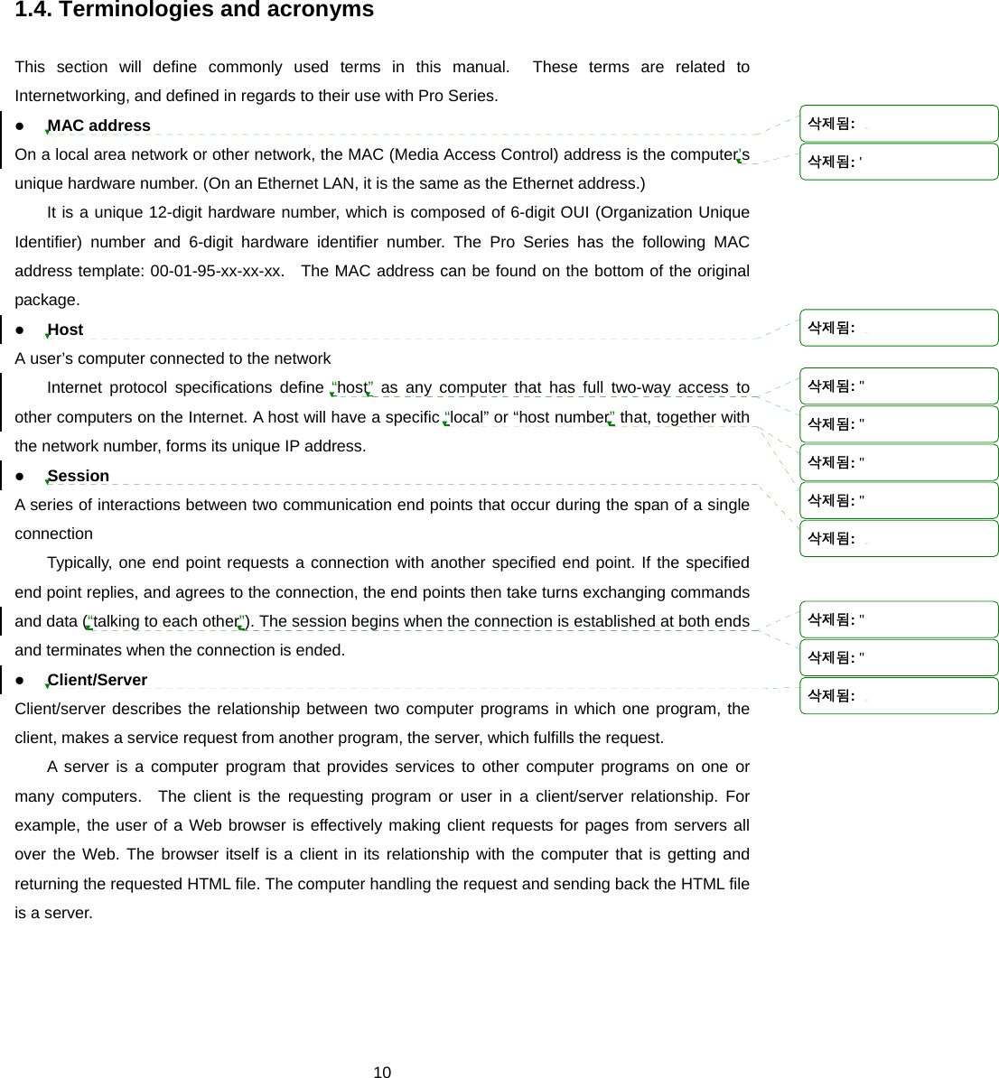
![101 ******* Hardware auto-detect and auto-test ******* [DRAM] DRAM Test ---------------------------------------------[ PASSED] [FLASH] FLASH Test ---------------------------------------------[ PASSED] [EEPROM] EEPROM Test ---------------------------------------------[ PASSED] [ETHERNET] ETHERNET Test ---------------------------------------------[ PASSED] [UART] <--Internal Loop Test--> Port # 1 test in progressing(MODE)------------------------[ RS232] (Read/WRite)------------------[ SUCCESS] Port # 2 test in progressing(MODE)------------------------[ RS232] (Read/WRite)------------------[ SUCCESS] Port # 3 test in progressing(MODE)------------------------[ RS232] (Read/WRite)------------------[ SUCCESS] Port # 4 test in progressing(MODE)------------------------[ RS232] (Read/WRite)------------------[ SUCCESS] <--External Uart Test--> Port # 1 test in progressing(MODE)------------------------[ RS232] (Read/WRite)------------------[ SUCCESS] (RTS/CTS)---------------------[ SUCCESS] (DTR/DSR)---------------------[ SUCCESS] Port # 2 test in progressing(MODE)------------------------[ RS232] (Read/WRite)------------------[ SUCCESS] (RTS/CTS)---------------------[ SUCCESS] (DTR/DSR)---------------------[ SUCCESS] Port # 3 test in progressing(MODE)------------------------[ RS232] (Read/WRite)------------------[ SUCCESS] (RTS/CTS)---------------------[ SUCCESS] (DTR/DSR)---------------------[ SUCCESS] Port # 4 test in progressing(MODE)------------------------[ RS232] (Read/WRite)------------------[ SUCCESS] (RTS/CTS)---------------------[ SUCCESS] (DTR/DSR)---------------------[ SUCCESS] ******* Hardware auto-detect and auto-test SUMMARY ******* 1. DRAM Test -----------------------------------------[ PASSED] 2. FLASH Test -----------------------------------------[ PASSED] 3. EEPROM Test -----------------------------------------[ PASSED] 4. ETHERNET Test -----------------------------------------[ PASSED] 5. UART Test Summary ----------------------------------------------------------------------------- Port Number |Port Mode | Data Communication Test | RTS/CTS | DTR/DSR | ----------------------------------------------------------------------------- Port # 1(Internal) | UNKNOWN | FAILED | SKIPPED | SKIPPED | Port # 1(External) | UNKNOWN | FAILED | FAILED | FAILED | ----------------------------------------------------------------------------- Port # 2(Internal) | UNKNOWN | FAILED | SKIPPED | SKIPPED | Port # 2(External) | UNKNOWN | FAILED | FAILED | FAILED | ----------------------------------------------------------------------------- Port # 3(Internal) | UNKNOWN | FAILED | SKIPPED | SKIPPED | Port # 3(External) | UNKNOWN | FAILED | FAILED | FAILED | ----------------------------------------------------------------------------- Port # 4(Internal) | UNKNOWN | FAILED | SKIPPED | SKIPPED | Port # 4(External) | UNKNOWN | FAILED | FAILED | FAILED | Hardware test is end. Press any key to return the test menu!! Figure A-9 Hardware test screen within Bios Menu Program For each hardware component test, the user can skip a test by pressing the <ESC> key. 삭제됨: 삭제됨: 삭제됨: 삭제됨: 삭제됨: 삭제됨: 삭제됨: 삭제됨: 삭제됨: -----------------------------------------------------------------------------삭제됨: -----------------------------------------------------------------------------삭제됨: 삭제됨:](https://usermanual.wiki/SENA-TECHNOLOGIES/PSX10W/User-Guide-888756-Page-101.png)
![102------------------------------------------------------------------------------- Hardware Test ------------------------------------------------------------------------------- Select menu 0. Test Mode - One Time 1. Auto test 2. DRAM test 3. FLASH test 4. EEPROM test 5. Ethernet test 6. UART Mode test <ESC> Back, <ENTER> Refresh -----> 1 ******* Hardware auto-detect and auto-test ******* [DRAM] DRAM Test ---------------------------------------------[SKIPPED] [FLASH] FLASH Test ---------------------------------------------[SKIPPED] Figure A-10 Skip the specific test using ESC key A 4.5. Firmware upgrade menu By using the ‘Firmware upgrade’ menu, the user can upgrade the firmware of the unit. Before firmware upgrade, the user can check the current firmware version by selecting menu item 3 from the Main menu page. The firmware upgrade menu supports only the TFTP protocol for remote firmware download. If the user would like to download firmware from TFTP server, he must also set the IP address for the unit properly. The default IP address for the unit is 192.168.161.5. For firmware upgrade, a firmware file configured as [Firmware File Name] on the server configured as [Server’s IP address] must exist. ----------------------------------------------------------------------------- Firmware upgrade ----------------------------------------------------------------------------- Select menu 1. Protocol [TFTP] 2. IP address assigned to Ethernet interface [192.168.161.5] 3. Server's IP address [192.168.0.128] 4. Firmware File Name [ps.img] 5. Start firmware upgrade <ESC> Back, <ENTER> Refresh -----> Figure A-11 Firmware upgrade menu within Bios Menu Program If the user selects [Start firmware upgrade], a confirmation message will be displayed on the screen. If the user enters ‘y’, the firmware upgrade process will start. This process cannot be stopped until it has finished. 서식 있음: 글머리 기호 및번호 매기기삭제됨: -------------------------------------------------------------------------------삭제됨: 삭제됨: 삭제됨:](https://usermanual.wiki/SENA-TECHNOLOGIES/PSX10W/User-Guide-888756-Page-102.png)
![103 ----------------------------------------------------------------------------- Firmware upgrade ----------------------------------------------------------------------------- Select menu 1. Protocol [TFTP] 2. IP address assigned to Ethernet interface [192.168.6.6] 3. Server’s IP address [192.168.6.1] 4. Firmware File Name [psx10W.img] 5. Start firmware upgrade <ESC> Back, <ENTER> Refresh -----> 5 Firmware upgrade cannot be stopped until finished. And all configuration parameters are restored to default values. Do you really want to start firmware upgrade(y/n)?y net trying to load image.... TFTP Boot image(psx10W.img) loading at 0xb00000.. 3019495 Bytes 3019495 bytes receive done. kernel upgrade start. Kernel Block : Write to Flash... done kernel upgrade complete. Cramfs upgrade start. Cramfs Block : Write to Flash... done Cramfs upgrade complete. Configuration upgrade start. Configuration Block : Write to Flash... done Configuration upgrade complete. Firmware upgrade is finished successfully.. ----------------------------------------------------------------------------- Firmware upgrade ----------------------------------------------------------------------------- Select menu 1. Protocol [TFTP] 2. IP address assigned to Ethernet interface [192.168.161.5] 3. Server’s IP address [192.168.0.128] 4. Firmware File Name [ps.img] 5. Start firmware upgrade <ESC> Back, <ENTER> Refresh -----> Figure A-12 Firmware upgrade process After finishing the firmware upgrade process, the program will display the main menu along with a success message. 삭제됨: -----------------------------------------------------------------------------삭제됨: -----------------------------------------------------------------------------삭제됨: '삭제됨: 삭제됨: 삭제됨: 삭제됨: 삭제됨: 삭제됨: -----------------------------------------------------------------------------삭제됨: '](https://usermanual.wiki/SENA-TECHNOLOGIES/PSX10W/User-Guide-888756-Page-103.png)


![페이지 57: [1] 삭제됨 염한준 2007-01-04 PM 3:54:00 TCP 연결이 이루어 지고 나서 Data를 주고 받을 때, 어떤 형식으로 주고 받을지를 지정할수있습니다. Default data mode가 ‘Raw TCP’로 설정되어 있을시에는 데이터에 아무런 가공을 하지 않은 상태로 데이터를 주고 받습니다. 페이지 57: [2] 삭제됨 염한준 2007-01-04 PM 4:03:00 Default data mode가 ‘Telnet binary’로 지정되어 있을시에는, Modem emulation mode에서 텔넷 COM 포트 제어 옵션을 지원합니다. 대개 이 옵션은 RFC2217호환 COM 포트 리다이렉터(Redirector)와 함께 사용되어 사용자는 본인의 시리얼 포트 어플리케이션 프로그램을 사용하여 Pro Series의 시리얼 포트 매개 변수를 제어할 수 있습니다.](https://usermanual.wiki/SENA-TECHNOLOGIES/PSX10W/User-Guide-888756-Page-112.png)