SES imagotag AP0001 digital network controller transceiver User Manual Product Specification AP 2010
imagotag GmbH digital network controller transceiver Product Specification AP 2010
Contents
- 1. Quick start guide
- 2. User manual
User manual

1.1 Key Features ................................................................................................................................................ 4
2.1 Front, Side and Top View ............................................................................................................................. 5
2.2 Upper Surface .............................................................................................................................................. 5
2.3 Side View...................................................................................................................................................... 6
2.4 Rear View ..................................................................................................................................................... 6
2.5 Status LED Colors ......................................................................................................................................... 7
2.6 Mechanical Dimensions ............................................................................................................................... 7
3.1 Used Channels ............................................................................................................................................. 8
3.2 Cabel Specifications ..................................................................................................................................... 8
3.3 Power Supply Specifications ........................................................................................................................ 9
3.4 Barcode Information .................................................................................................................................. 10
4.1 General Technical characteristics .............................................................................................................. 11
4.2 Power and Current Consumption .............................................................................................................. 11
4.3 General Specifications ............................................................................................................................... 11
5.1 Mounting Location Specifications ............................................................................................................. 12
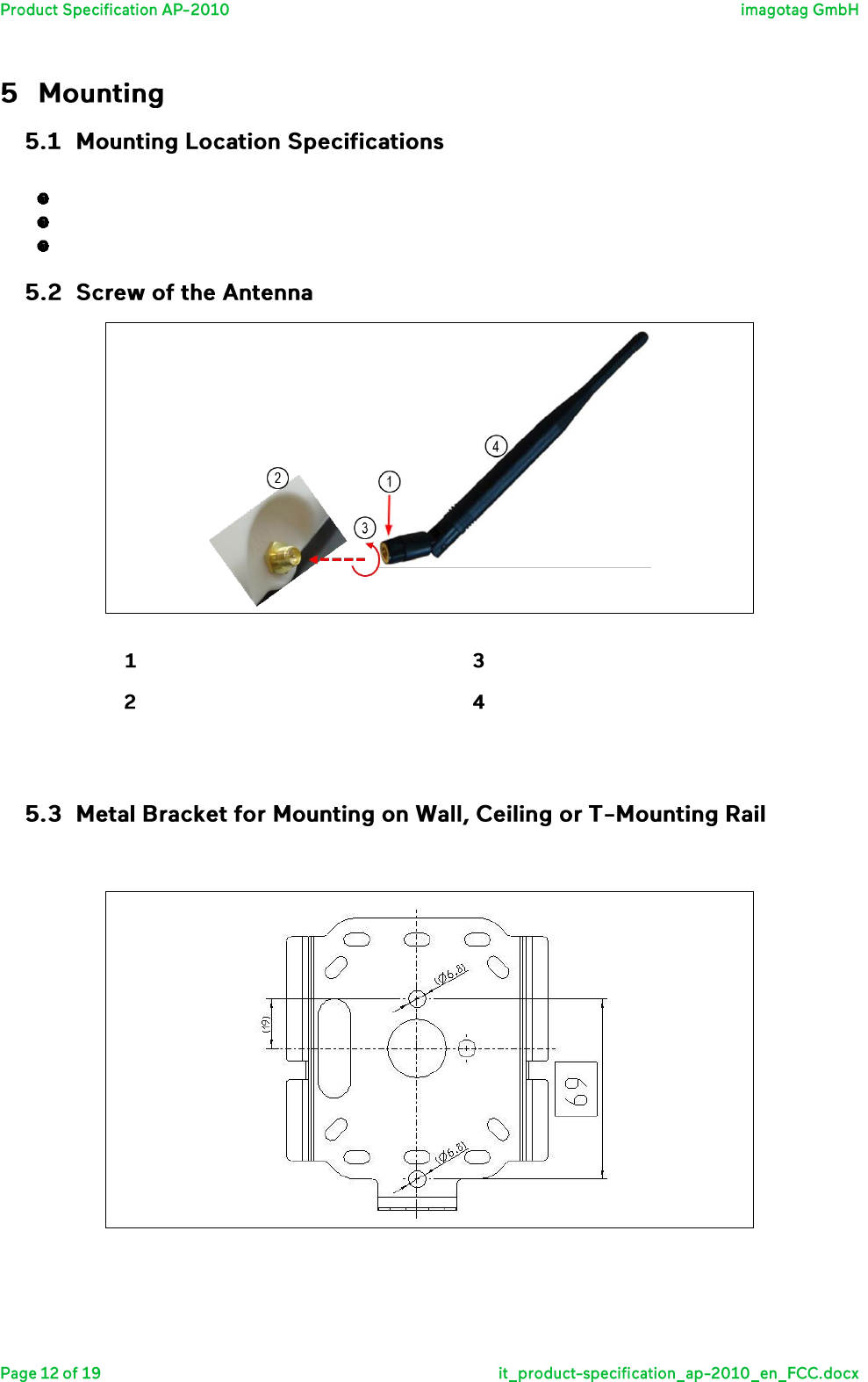
5.2 Screw of the Antenna ................................................................................................................................ 12
5.3 Metal Bracket for Mounting on Wall, Ceiling or T-Mounting Rail ............................................................. 12
6.1 Humidity and Operating Conditions .......................................................................................................... 15
6.2 Storage Conditions ..................................................................................................................................... 15
6.3 Cleaning Instructions ................................................................................................................................. 15
7.1 Packing Dimensions ................................................................................................................................... 16
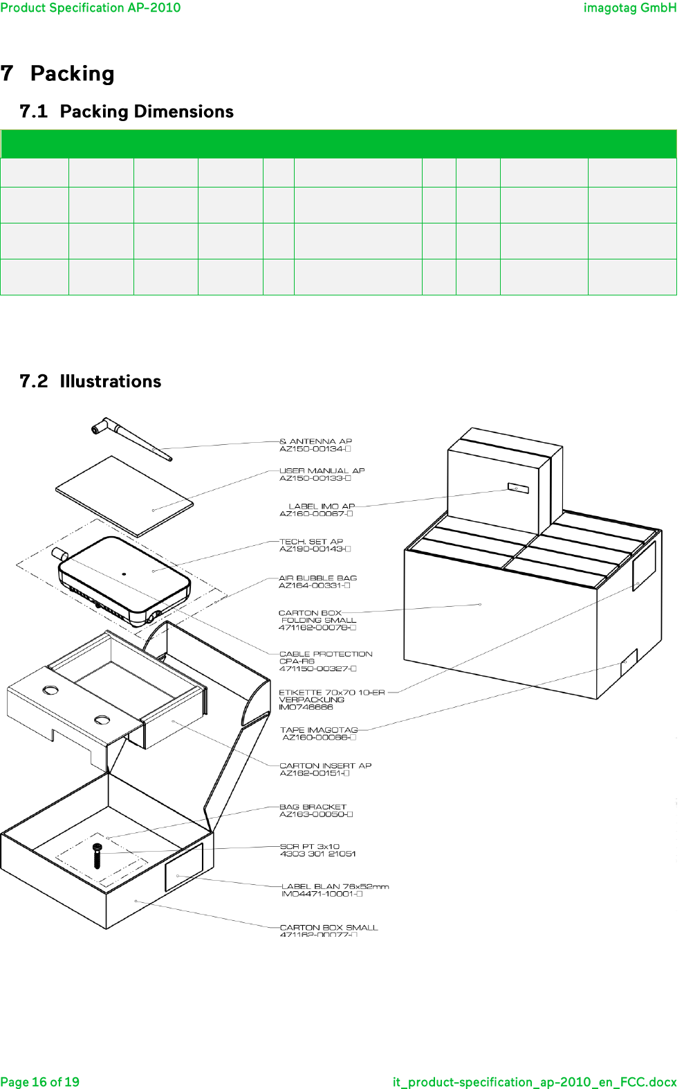
7.2 Illustrations ................................................................................................................................................ 16
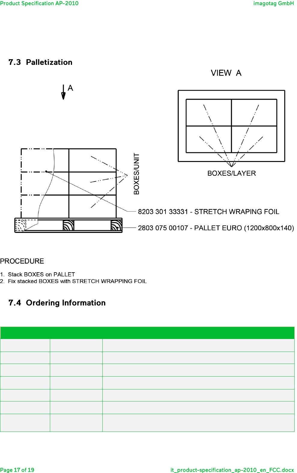
7.3 Palletization ............................................................................................................................................... 17
7.4 Ordering Information ................................................................................................................................. 17

8.1 Applied Standards ...................................................................................................................................... 18
8.2 Declaration ................................................................................................................................................. 18

The Access Point AP-2010 by imagotag is a network device similar to WLAN access points that is required for
communication with the imagotag electronic shelf labels (transmits price information to the labels).
Up to 10 000 labels can be managed per access point and the self-organizing network allows automatic
roaming of labels without manual handling. The high transmission rate of the 2.4 GHz wireless technology
and the intelligent task scheduling enables fast and secure updates on imago G1 labels of all sizes.
This document is the technical specification of the Access Point AP-2010.
Manages up to 10 000 imago G1 labels of all sizes
Covers up to 2 000 m² (depending on shop layout)
Low power consumption – powered by PoE (Power over Ethernet) or with low power plug
Easy configuration and monitoring
Optimized scheduling of tasks and self-managed roaming of labels
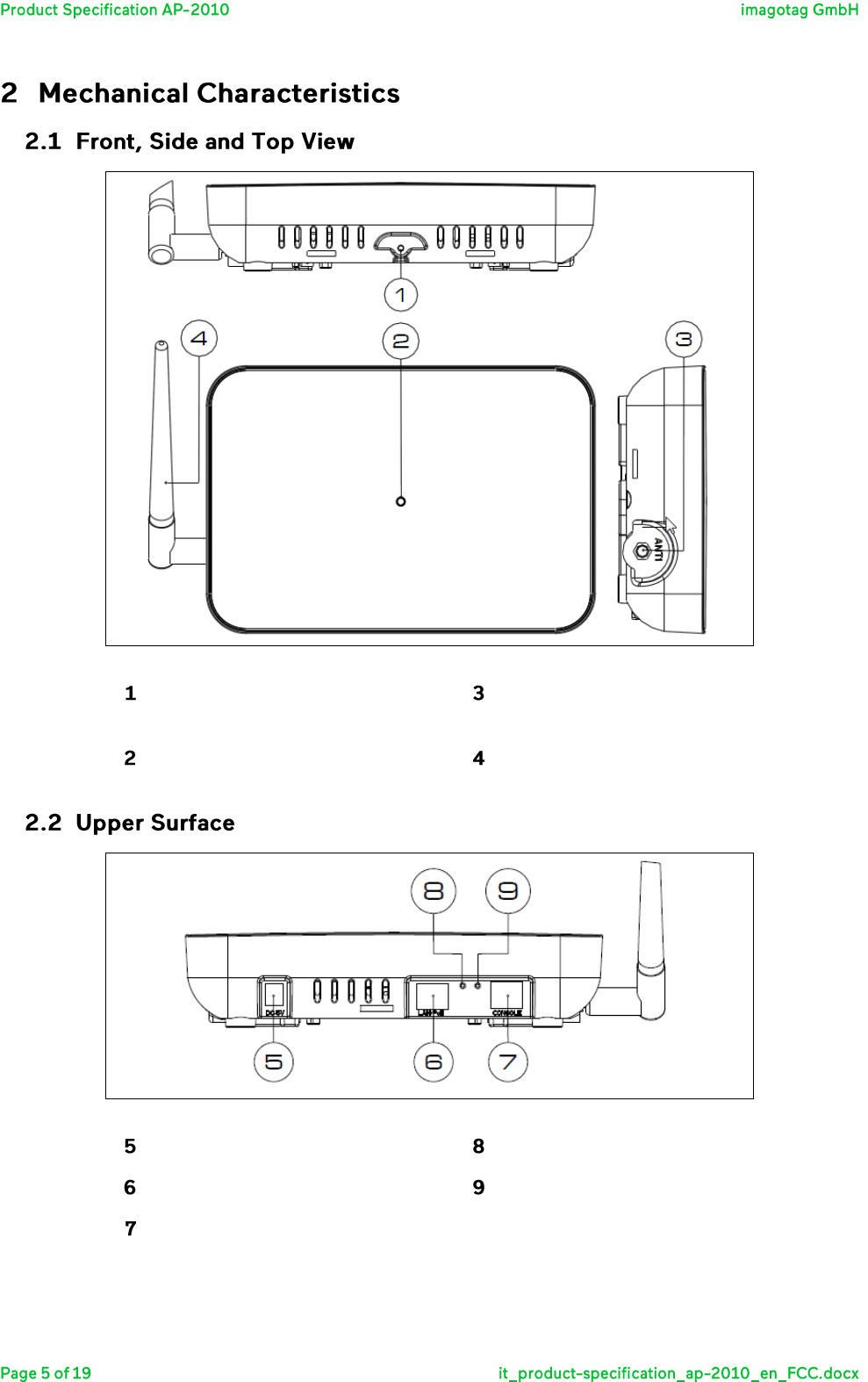
Front, side and top view of the AP-2010
Mounting plate fixation screw-
hole
Antenna socket
LED
Antenna
Top view of the imagotag AP-2010
Connection for the Power Supply
Reset
LAN/PoE
unused
Console
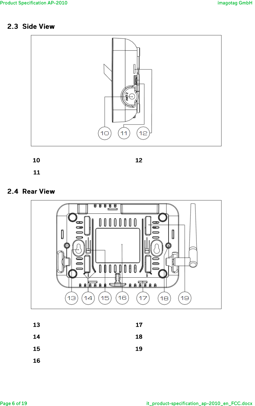
Side view of the imagotag AP-2010
Antenna Connector (unused)
Snap Connector Housing
Warranty Seal
Rear view of the imagotag AP-2010
Mounting Tab
Snap Connector Housing
Mounting Rail
Housing Screw
Locking Tab
Mounting Profile
Label
Color
Description
Note
Red
Boot process
Error
Can take about 2 minutes, if it takes much longer, the device is
defective and there is a need for service.
Blue
Normal mode
---
Yellow
Operational, but not connected
to any server
---
Red (blinking)
Running Firmware Update
During this time there is no connection to the electronic label
With antenna:
Outline (mm): 226 x 135 x 45
Weight: 350 g
Without antenna:
Outline (mm): 196 x 135 x 45
Weight: 320 g
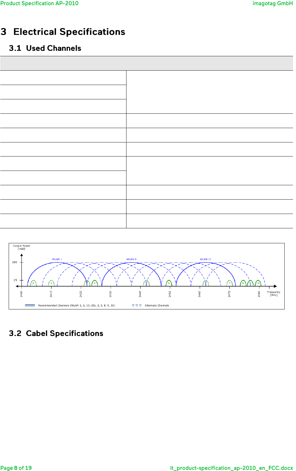
Kanal
Frequenz
WLAN Kanal (802.11b/g)
0
2404 MHz
WLAN 1 (2402 – 2422 MHz)
1
2010 MHz
2
2422 MHz
3
2425 MHz
4
2442 MHz
WLAN 6 (2427 – 2447 MHz)
5
2445 MHz
6
2462 MHz
WLAN 11 (2452 – 2472 MHz)
7
2470 MHz
8
2474 MHz
9
2477 MHz
10
2480 MHz
Overview of used channels of the imagotag AP-2010
Visualization of used channels of the imagotag AP-2010
You can use a commercially available LAN cable (CAT-5 or higher) for data connection and the power supply
(if PoE is used) of the imagotag AP-2010.
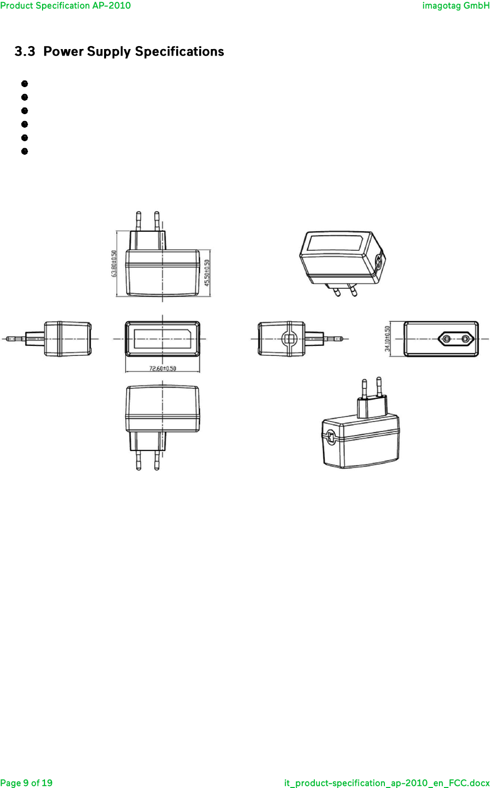
Sunny Computer Technology Europe s.r.o.
Model: SYS1449-1505-W2E
Input: 100-240 V ~ 1.0 A MAX, 50-60Hz
Output: 5V 3A
Output Power: 15W MAX
Operating Temperature: 0° C to + 45° C
Dimension (mm): 72.5 x 34 x 45
Note: This is the European version
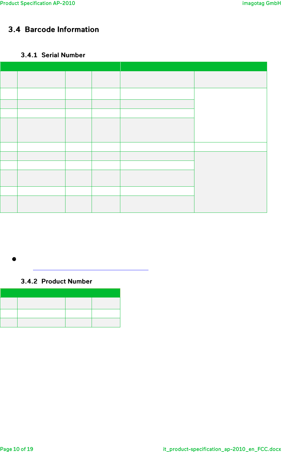
The AP-2010 comes with an AP-ID, P/N, MAC and S/N. The AP-ID consists of 5 decimal digits (0-9).
Part
Description
Format
Example
Comment
Source
A
Production fab
2 alpha
01
Specified by imagotag
once for each fab
B
Product family
2 alpha
A1
Specified by imagotag in
the product specification
document
C
Type identifier
2 hex
A0
D
Product version
2 alpha
02
E
Product
revision
3 alpha
004
Incremented on every
change of product
specification
-
Separator
“-“
-
Fixed
F
Internal
1 alpha
I
Internal
Calculated during
production
G
Year
2 dec
12
H
Week
2 dec
38
Calendar week in current
year (01-53)
I
Weekday
1 dec
5
J
Internal
4 dec
1133
Continuous Serial Number
(Counter)
S/N Format: AABBCCDDEEE-FGGHHIJJJJ
S/N Example: 01A1A002004-I123851133
Note:
Calendar week date is calculated according to ISO 8601
(see http://en.wikipedia.org/wiki/ISO_week_date)
Part
Description
Format
Example
B
Product family
2 alpha
A1
C
Type identifier
2 hex
A0
D
Product version
2 alpha
02
P/N Format: BBCCDD
P/N Example: A1A001
Power:
External Power Supply: 5 VDC / 3A
Power Supply via PoE: IEEE 802.3af, IEEE 802.3at
Power consumption: 15W MAX, typical 3W
Technology:
Radio technology: proprietary
Operating frequency: 2.4 GHz (ISM-Band) – 2.4835 GHz
Transmitted power: ≤ 10 dBm
Number of Channels: 11
Access protocol: proprietary
Power consumption measurements indicate that the AP-2010 has the following patterns:
Operating Current: ≤ 60 mA (max. current)
Operating Power: ≤ 280 mW
Supply Voltage: 5V ± 10%
600 MHz ARM Cortex-A8
Memory - 256MB DDR2 memory
256MB NAND Flash
SD/MMC card connector
o 512 MB card with imagotag software preinstalled
Power over Ethernet (PoE IEEE 802.3af / IEEE 802.3at)
o The original IEEE 802.3af-2003 PoE standard provides up to 15.4 W of DC power (minimum
44 V DC and 350 mA to each device). Only 12.95 W is assured to be available at the powered
device as some power is dissipated in the cable.
Other Interfaces
o Serial RS232 Interface
o 10/100 Ethernet Interface
Power
o Power source options (DC, PoE)
o 3.3 V I/O operation
o DC supply 5V ± 10%, 3A Max
OS: Embedded Linux (Kernel: 2.6.32)
imago AP-2010 application software in latest version (current 1.0.4)
imago RF Firmware in latest version (current 2.0.6)
The Access Point could be mounted on a:
Concrete wall
Mortar wall
T-Mounting Rail
Screw of the Antenna
Front Part
Direction of Rotation
Connection Socket
Rear Part (Swiveling)
Note: Screw the antenna with only the front part (1)
Once the metal bracket is mounted, the AP-2010 will be mechanical connected and fixed with a fixing screw.
Metal Bracket for imagotag AP-2010
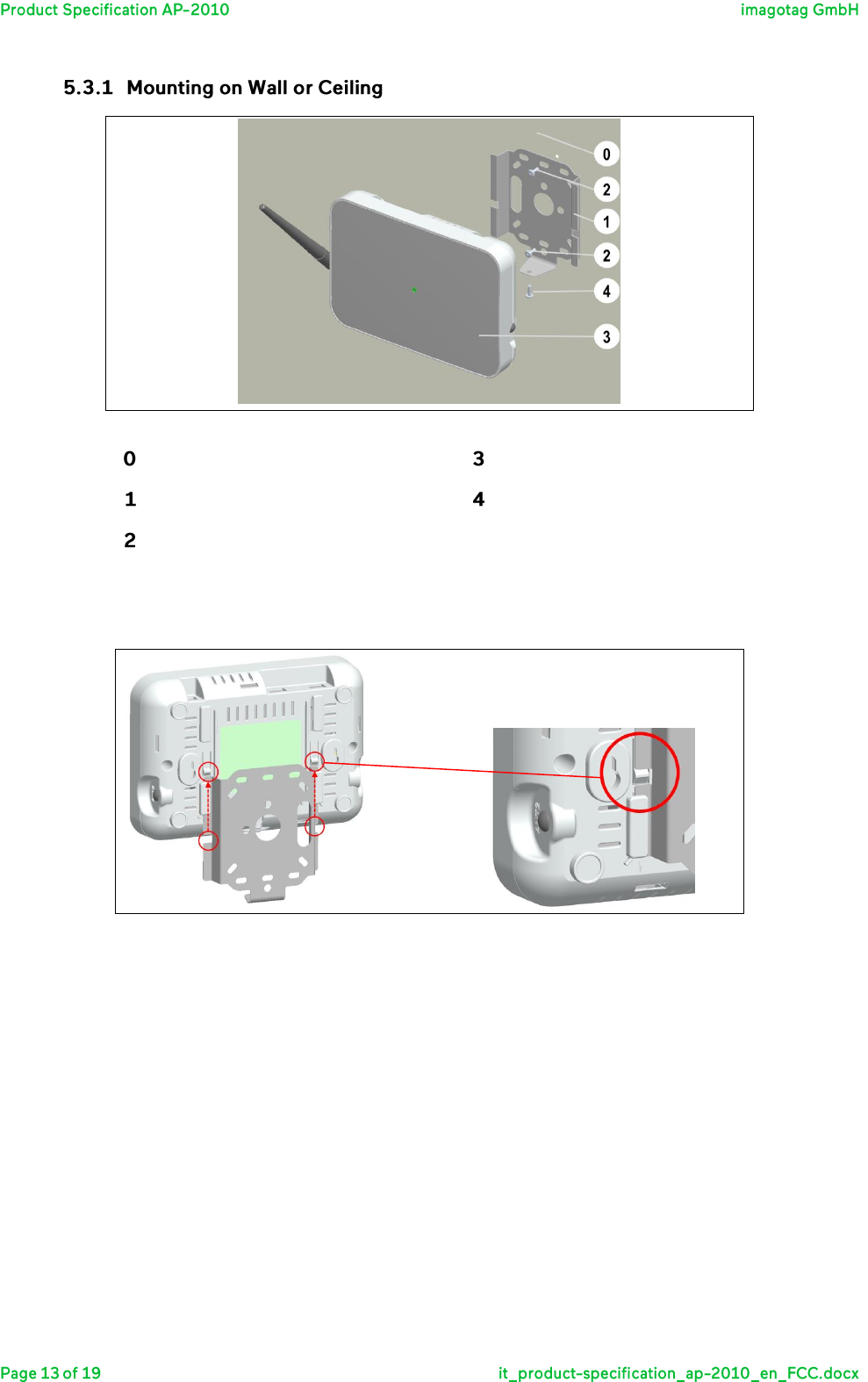
Wall or Ceiling Mounting (Scheme)
Mounting Surface
imagotag AP-2010
Metal Bracket
Fixation Screw
Mounting Screw
a. Install the metal bracket to the wall or ceiling with the help of dowels and mounting screws.
imagotag AP-2010 Locking Tabs
b. Slide the access point to the mechanical lock of the locking tabs
c. Attach the AP-2010 with the enclosed fixation screw to the metal bracket
Attach the metal bracket using the included “caddy® clips” from Erico® and the enclosed, self-locking screw
nuts M6.
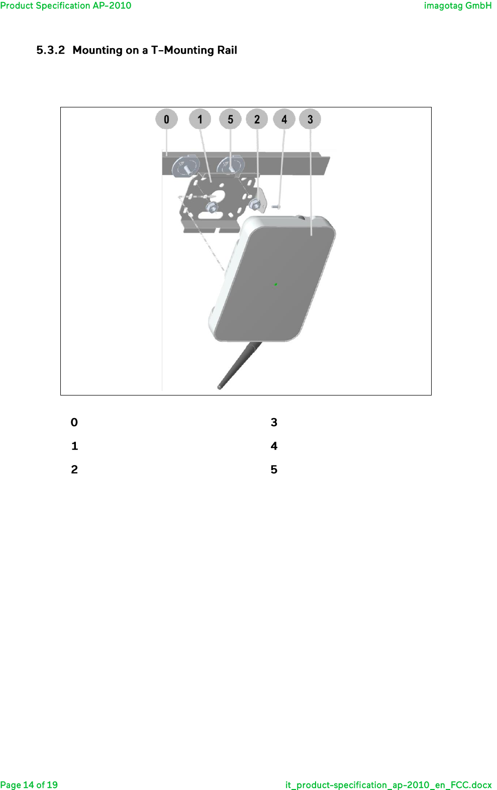
Mounting an AP-2010 on a T-Mounting Rail
T-Mounting Rail
imagotag AP-2010
Metal Bracket
Fixation Screw
Self-locking Screw Nuts M6
ERICO® „caddy® clips“
a. Place 2 pieces of “caddy® clips” with the right distance on the T-Mounting Rail and fix it (twist)
b. Place the metal bracket
c. Fix the Metal Bracket with 2 pieces of the self-locking screw nuts M6
d. Slide the access point to the mechanical lock of the locking tabs
e. Attach the AP-2010 with the enclosed fixation screw to the metal bracket

Turned OFF:
Temperature: -20° C to + 70° C
Humidity: 10% to 85% (non-condensing)
Turned ON:
Temperature: 0° C to + 40° C
Humidity: 10% to 80% (non-condensing)
Temperature: -20 °C to + 70 °C
Humidity: 10% to 85% (non-condensing)
Steps:
1) Shutdown Access Point
2) Plug Out Power Supply (AC or PoE)
3) Clean the Access Point with the help of a damp cloth
Note: Do not use liquid or aerosol cleaners.
DIMENSIONS
STACKING
QUANTITY
LENGTH
WIDTH
HEIGHT
BOX
520
350
260
LAYER / UNIT
3
SETS / BOX
10
PALLET
1200
800
140
BOXES / LAYER
4
SETS / LAYER
40
UNIT
1200
800
960
BOXES / UNIT
12
SETS / UNIT
120
Imagotag AP-2010 / Box: 10
You can choose between the following offered packages & accessories of the AP-2010:
Article Number
Model
Description
120002
AP-2010
AP-2010 incl. Antenna
120003
AP-2010
AP-2010 Bundle incl. Antenna and PSU (EUR)
120004
AP-2010
AP-2010 Bundle incl. Antenna and mounting plate
120008
AP-2010
AP-2010 Bundle incl. Antenna, PSU (EUR) and mounting plate
130001
Antenna
ANT OMNI 5 RP SMA INDOOR
120007
Mounting Plate
Mounting Plate
120005
AP-2010 PSU
(EUR)
Power Supply
Housing, board and the display of the imagotag AP-2010 conform with the ROHS
Directive
The product meets the EU safety, health and environmental protection requirements
and has the approval of CE marking
Information Technology Equipment
EN 60950-1/A2:2013
UL 60950-1/A2:2014
CSA CAN/CSA-C22.2 NO.60950-1-07
EMV
EN 301489-17 V2.2.1
R&TTE
EN 300328 V1.8.1
Human Exposure to Electromagnetic Fields
EN 62479:2010
The company imagotag GmbH declares on his own responsibility that the AP-2010 corresponds to the
standards mentioned above.
This device complies with part 15 of the FCC Rules. Operation is subject to the following two conditions: (1)
This device may not cause harmful interference, and (2) this device must accept any interference received,
including interference that may cause undesired operation.
Changes or modifications not expressly approved by the party responsible for compliance could void the
authority to operate the equipment.
This device complies with Industry Canada licence-exempt RSS standard(s). Operation is subject to the
following two conditions: (1) this device may not cause interference, and (2) this device must accept any
interference, including interference that may cause undesired operation of the device.
Le présent appareil est conforme aux CNR d'Industrie Canada applicables aux appareils radio exempts de
licence. L'exploitation est autorisée aux deux conditions suivantes : (1) l'appareil ne doit pas produire de
brouillage, et (2) l'appareil doit accepter tout brouillage radioélectrique subi, même si le brouillage est
susceptible d'en compromettre le fonctionnement.
Don't drop it.
Keep it away from water.
Don’t use the AP-2010 with defective parts.
Don’t use the AP-2010 with spare parts and accessories which are not examined and
approved by the imagotag GmbH.
Unauthorized changes or modifications to the electronic label and their components
without the consent of imagotag GmbH are not allowed.
Don't throw defective batteries into the dustbin. Give them to a reprocessing
company.
Don't throw AP-2010 into the dustbin. Give them to a reprocessing company.
Contact imagotag GmbH for more details about this process.