SES imagotag APG2-USB1-A digital network controller device User Manual
SES-imagotag GmbH digital network controller device
User Manual

Document Title Goes Here
Page 1
1.
2.
3.
a.
Test setup and specification for certification tests
Description
This page describes the quick-start with a per-defined test setup and how-to run tests with this setup.
FCC: This device complies with part 15 of the FCC Rules. Operation is subject to the following two conditions:
(1) This device may not cause harmful interference, and (2) this device must accept any interference received, including interference
that may cause undesired operation. Changes or modifications not expressly approved by the party responsible for compliance could void
the authority to operate the equipment.
IC: This device complies with Industry Canada licence-exempt RSS standard(s). Operation is subject to the following two conditions:
(1) this device may not cause interference, and (2) this device must accept any interference, including interference that may cause
undesired operation of the device.
Le présent appareil est conforme aux CNR d’Industrie Canada applicables aux appareils radio exempts de licence. L’exploitation est
autorisée
aux deux conditions suivantes : (1) l’appareil ne doit pas produire de brouillage, et (2) l’appareil doit accepter tout brouillage
radioélectrique subi,
même si le brouillage est susceptible d’en compromettre le fonctionnement.
Pr-requisites
Network cable
Local machine (laptop/PC)
Ethernet interface
Administration rights (to change the network settings)
JAVA Runtime Environment ( ), Version 8 or higherJRE
Test setup components
Core appliance 32GB - ID 52675 - 05CAB002303-I200000720
ESL Dongle - ID 50400
AP-2010 - ID TBA
USB pen drive incl. " " softwareControl Center
Initial test setup preparation
Prepare local machine
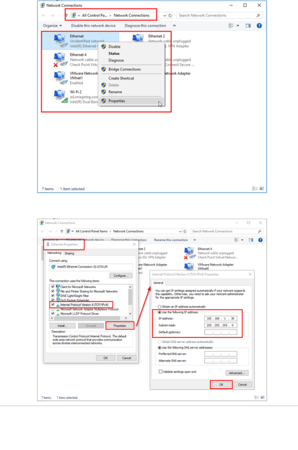
Change your Ethernet adapter settings
Control Panel - Network Connections
Right click on the desired Ethernet interface and select " "Properties
Document Title Goes Here
Page 2
3.
a.
4.
5. a.
b.
c.
1. a.
b.
Select " " and click " "Internet Protocol Version 4 (TCP/IPv4) Properties
Use the following IP address and subnet mask
IP address: 192.168.1.30
Subnet mask: 255.255.255.0
Prepare core appliance, ESL dongle and/or AP-2010
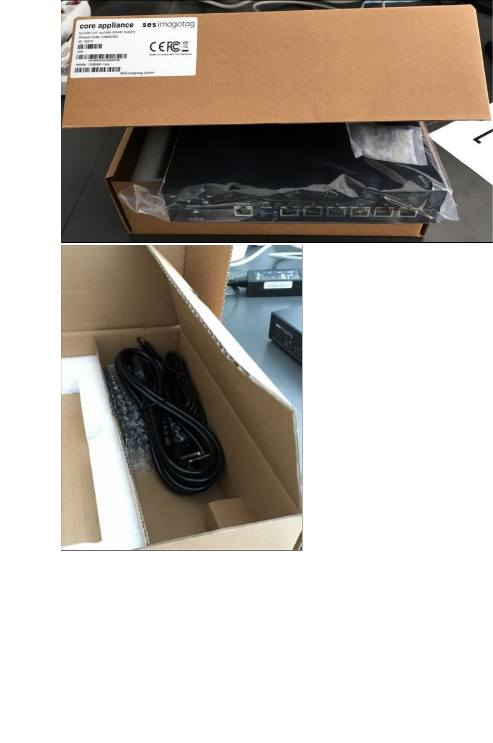
Unpack components
Unpack core appliance, power supply and ESL dongle.
Document Title Goes Here
Page 3
1.
b.
2. a.
b.
c.
d.
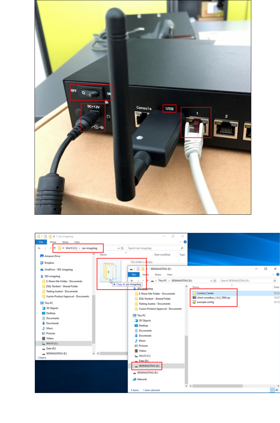
Connect components
Network cable Ethernet port " " & Ethernet port of your laptop or PC1
Power jack Power socket " "DC+12V
ESL Dongle USB port " "1
Document Title Goes Here
Page 4
2.
d.
3.
4. a.
b.
c.
d.
Power core appliance Power switch " "ON
Copy the following folder from the USB pen drive to your local computer: " "Control_Center
Example local directory: " "C:\ses-imagotag\
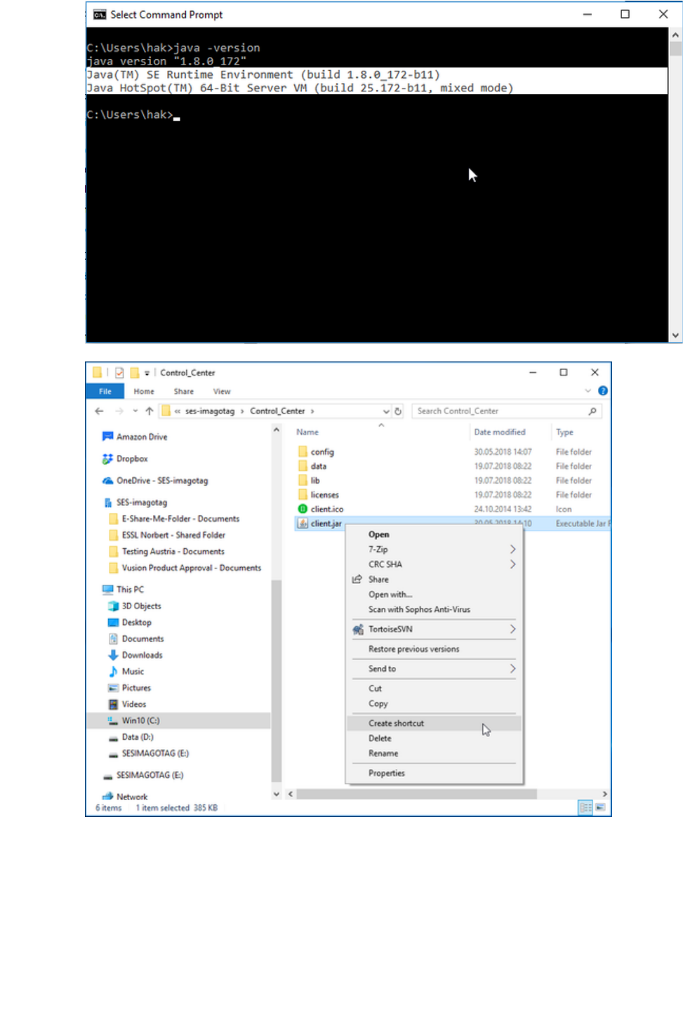
Make sure that JAVA is installed on your local machine. (e.g.: Open a windows command prompt and execute "java
" command)-version
Document Title Goes Here
Page 5
4.
d.
5.
a.
6.
7.
8.
a.
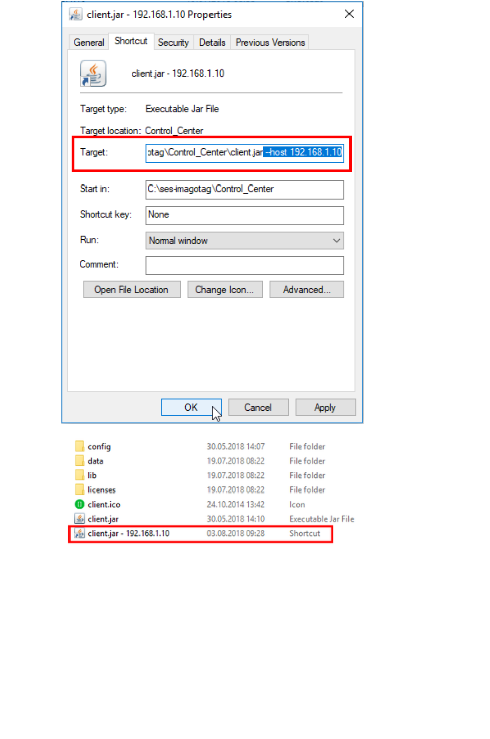
Create shortcut with " "client.jar
Rename shortcut to " "Control Center - 192.168.1.10
Edit shortcut with right click " "Properties
Add " " after " " as target link and apply the changes --host 192.168.1.10 client.jar
Document Title Goes Here
Page 6
8.
a.
9.
a.
10. a.
b.
11.
a.
Rename the shortcut to " "client.jar - 192.168.1.10
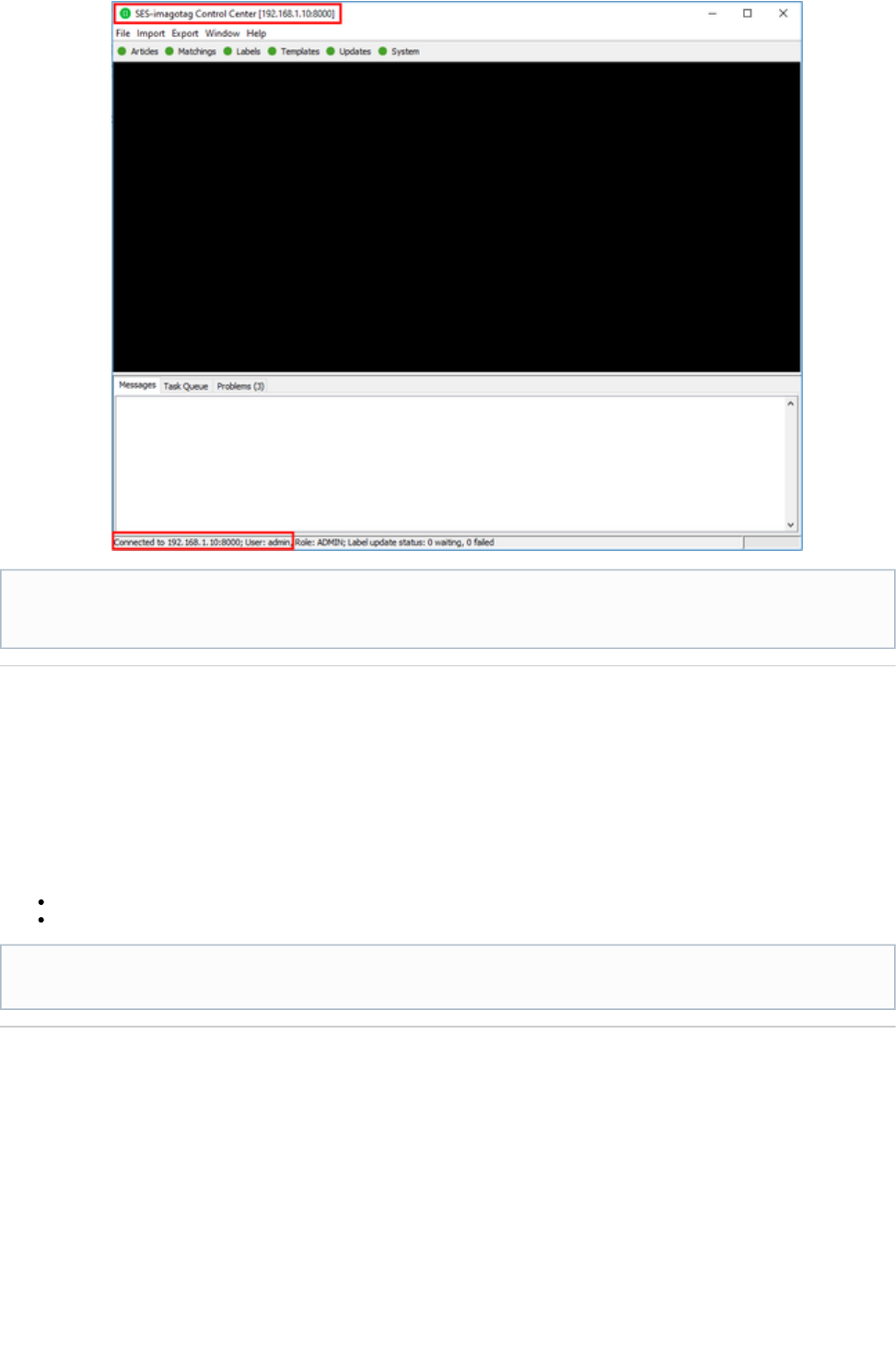
Execute the shortcut and use the following username/password combination to login:
Username: admin
Password: admin
Wait until the "Control Center" window opens
Document Title Goes Here
Page 7
11.
a.
1.
2.
a.
Working with labels
You'll find information about working with labels in the " "Core Service Quick Start Guide
10.1 Register labels
11.2 Sending images to labels
Sources:
https://portal.imagotag.com/get/documentation
https://portal.imagotag.com/files/all/docs/it_quick-start-guide_en.pdf
Operate the system with an AP-2010
This section describes how to change the operation from an ESL dongle to an AP-2010.
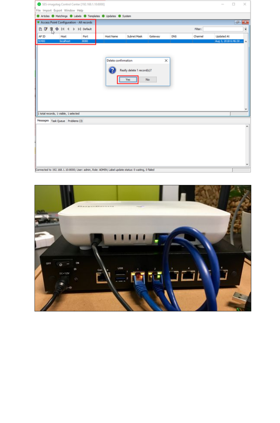
Unplug the ESL dongle
Delete the configuration of AP-ID "50400" via Control Center: " "System Access Point Configuration
Your system's now ready to start working with labels (register, send images, switch pages, ...)
Your current ESL channel is 10 (ESL dongle LED is blue)
Example images
The USB stick contains a collection of test images that can be sent to the labels.
Document Title Goes Here
Page 8
2.
a.
3. a.
b.
4.
5.
6.
a.
Connect the Ethernet interface of the AP-2010 with the of the core applianceEthernet port 2
Use the included network cable
Plug in the power supply of the access point
Wait until the AP-2010's LED turns blue
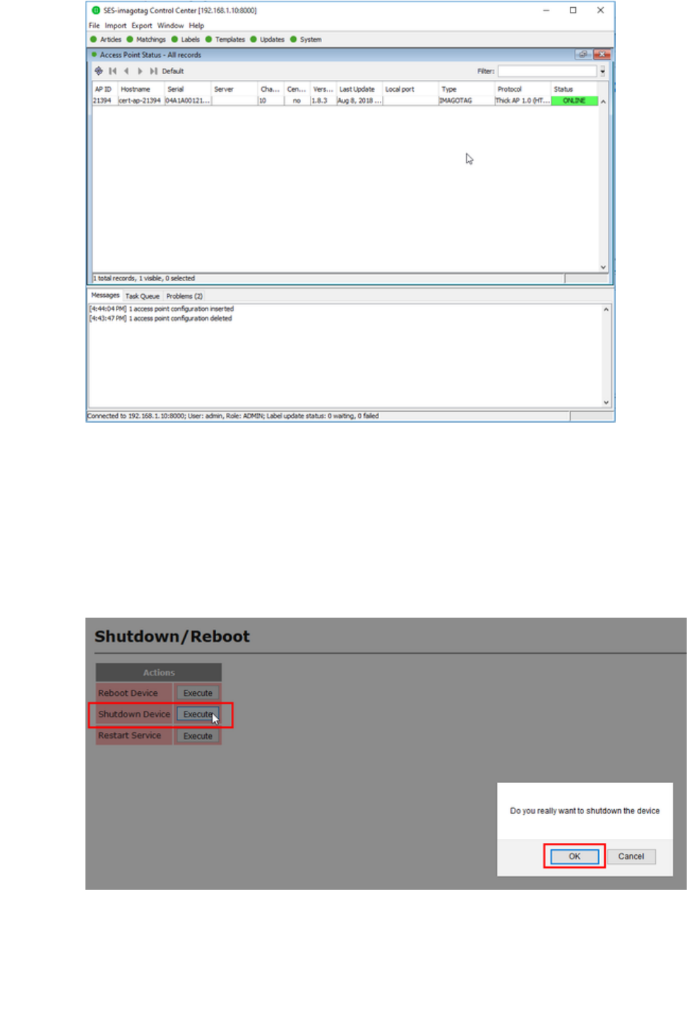
Check the Access Point status via Control Center: " "System Access Point Status
Document Title Goes Here
Page 9
6.
a.
1. a.
b.
c.
2. a.
b.
c.
d.
e.
3.
4.
5.
a.
Change back to the operation with ESL dongle
This section describes how to change the operation from an AP-2010 to an ESL dongle
Switch off the AP-2010
http://192.168.1.20/admin/shutdownReboot.xml Execute " "Shutdown Access Point
Wait until the LED turns RED
Plug out power supply
Turn off the core appliance
http://192.168.1.10/admin/shutdown.xml
Execute " "Shutdown Device
Wait for the device to shut down (LEDs off)
Power switch " "OFF
Plugin the ESL dongle to USB port "1"
Turn on core appliance Power switch " "ON
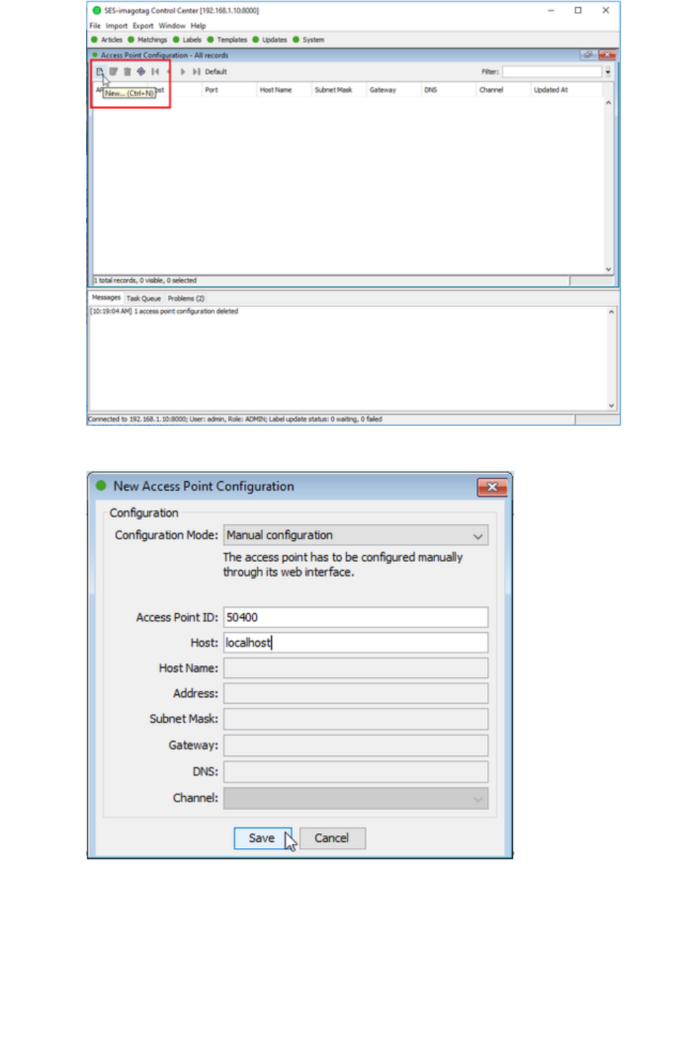
Add the configuration for the ESL dongle with ID "50400" via Control Center: " "System Access Point Configuration
Document Title Goes Here
Page 10
5.
a.
b.
c.
d.
e.
6.
7. a.
b.
c.
Fill " " with " " andAccess Point ID 50400
" " with " "Host localhost
Submit changes by " "Save
Wait until the ESL dongle's LED turns blue
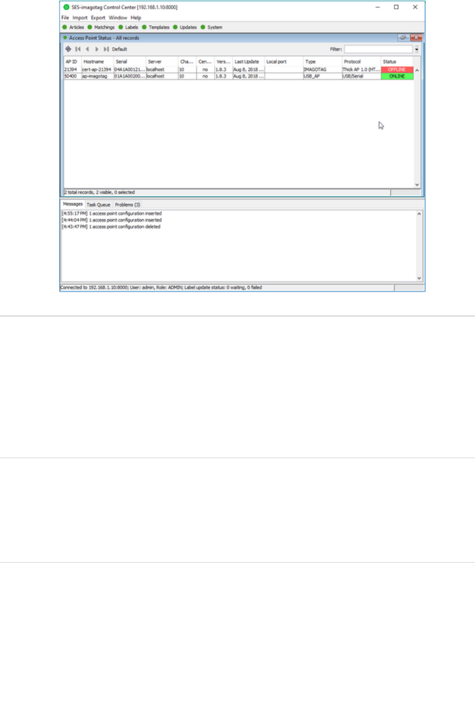
Check the Access Point status via Control Center: " "System Access Point Status
AP-2010 is " "OFFLINE
ESL dongle is " "ONLINE
Document Title Goes Here
Page 11
7.
c.
1.
2.
3.
4.
5.
6.
1.
2.
3.
Operate EMC Test
Take the prepared Sample with the channel you want to evaluate (CH 0, 4, 10)
Prepare the prepared counterpart with the same channel you chose (CH 0,4, 10)
Plug-in the power supply of the counterpart and put in the batteries of the EUT
The AP and the Label now start automatically to permanently exchange packets
If the transmission is OK, the LED will remain OFF. If a transmission fails the LED will be ON until the next successful
transmission of data.
You can check the functionality if a you unplug the counterpart The LED of the EUT should light up within 2 seconds.
Modulated/Unmodulated Output test
Take the EUT and put in the batteries
the label will send continuosly with maximum output power
You can start all required measurements for the certification report