SHARP Projector Manual L0907086
User Manual: SHARP SHARP Projector Manual SHARP Projector Owner's Manual, SHARP Projector installation guides
Open the PDF directly: View PDF ![]() .
.
Page Count: 73
®
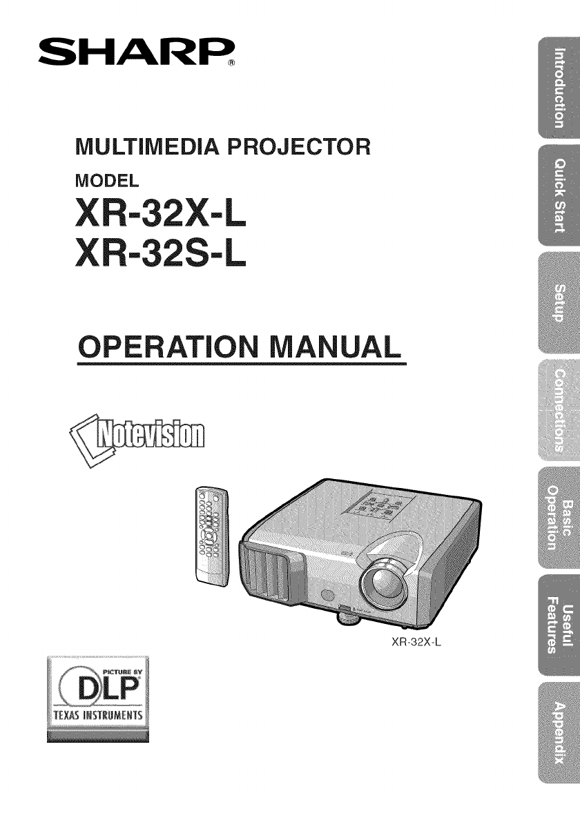
MULTiMEDiA PROJECTOR
MODEL
XR-32X-L
XR-32S-L
OPERATION MANUAL
XR-32X-L
iMPORTANT
• For your assistance in reporting the loss
or theft of your Projector, please record
the Model and Serial Number located on
the bottom of the projector and retain this
information.
,, Before recycling the packaging, please
ensure that you have checked the con-
tents of the carton thoroughly against the
list of "Supplied accessories" on page 10.
SPECIAL NOTE FOR USERS INTHE U.K.
The mains lead of this product is fitted with a non-rewireable (moulded) plug incorporat-
ing a 10A fuse. Should the fuse need to be replaced, a BSI or ASTA approved BS 1362
fuse marked _ or <_ and of the same rating as above, which is also indicated on the pin
face of the plug, must be used.
Always refit the fuse cover after replacing the fuse. Never use the plug without the fuse
cover fitted.
In the unlikely event of the socket outlet in your home not being compatible with the plug
supplied, cut off the mains plug and fit an appropriate type.
DANGER:
The fuse from the cut-off plug should be removed and the cut-off plug destroyed immedi-
ately and disposed of in a safe manner.
Under no circumstances should the cut-off plug be inserted elsewhere into a 13A socket
outlet, as a serious electric shock may occur.
To fit an appropriate plug to the mains lead, follow the instructions below:
WARNING:
THIS APPARATUS MUST BE EARTHED.
IMPORTANT:
The wires in this mains lead are coloured in accordance with the following code:
Green-and-yellow :Earth
Blue :Neutral
Brown :Live
As the colours of the wires in the mains lead of this apparatus may not correspond with the
coloured markings identifying the terminals in your plug proceed as follows:
• The wire which is coloured green-and-yellow must be connected to the terminal in the
plug which is marked by the letter E or by the safety earth symbol _L=or coloured green or
green-and-yellow.
• The wire which is coloured blue must be connected to the terminal which is marked with
the letter N or coloured black.
• The wire which is coloured brown must be connected to the terminal which is marked with
the letter L or coloured red.
IF YOU HAVEANY DOUBT, CONSULT A QUALIFIED ELECTRICIAN.
===
|||
ThesuppliedCD-ROMcontainsoperationinstructionsinEnglish,German,French,
Spanish,Italian,Dutch,Swedish,Portuguese,Chinese,KoreanandArabic.Carefully
readthroughtheoperationinstructionsbeforeoperatingtheprojector.
DiemitgelieferteCD-ROMenth_.ltBedienungsanleitungeninEnglisch,Deutsch,FranzOsisch,
Spanisch,Italienisch,Niederl_.ndisch,Schwedisch,Portugiesisch,Chinesisch,Koreanischund
Arabisch.BittelesenSiedieBedienungsanleitungvorderVerwendungdesProjektors
sorgf_.ltigdurch.
LeCD-ROMfournicontientlesinstructionsdefonctionnementenanglais,allemand,
francais,espagnol,italien,neerlandais,suedois,portugais,chinois,coreenetarabe.
Veuillezlireattentivementcesinstructionsavantdefairefonctionnerleprojecteur.
ElCD-ROMsuministradocontieneinstruccionesdeoperaci0neningles,alema.n,
frances,espanol,italiano,holandes,sueco,portugues,chino,coreanoy&abe.Lea
cuidadosamentelasinstruccionesdeoperaci0nantesdeutilizarelproyector.
IICD-ROMindotazionecontieneistruzioniperI'usoininglese,tedesco,francese,
spagnolo,italiano,olandese,svedese,portoghese,cinese,coreanoearabo.Leggere
attentamenteleistruzioniperI'usoprimadiusareilproiettore.
DemeegeleverdeCD-ROMbevathandleidingeninhetEngels,Duits,Frans,Spaans,
Italiaans,Nederlands,Zweeds,Portugees,Chinees,KoreaansenArabisch.Leesde
handleidingzorgvuldigdoorvoorudeprojectoringebruikneemt.
DenmedfOljandeCD-ROM-skivaninneh_llerbruksanvisningarp_engelska,tyska,
franska,spanska,italienska,hollb.ndska,svenska,portugisiska,kinesiska,koreanskaoch
arabiska.Lb.snogaigenombruksanvisningeninnanprojektorntasibruk.
OCD-ROMfornecidoconteminstru_6esdeopera_gtoemIngl6s,Alemgto,Franc6s,
Espanhol,Italiano,Holand6s,Sueco,Portugu6s,Chin6s,CoreanoeArabe.Leia
cuidadosamentetodasasinstru_6esdeopera_gtoantesdeoperaroprojetor.
o .o>x11_k_l€-xl_l-{-<l_.
3h->. 0i>0L>.
iv
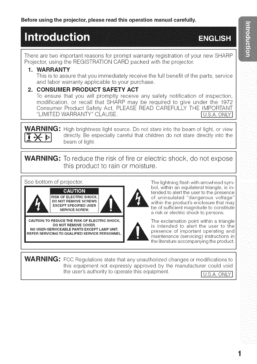
Before using the projector, please read this operation manual carefully.
There are two important reasons for prompt warranty registration of your new SHARP
Projector, using the REGISTRATION CARD packed with the projector.
1. WARRANTY
This is to assure that you immediately receive the full benefit of the parts, service
and labor warranty applicable to your purchase.
2. CONSUMER PRODUCT SAFETY ACT
To ensure that you will promptly receive any safety notification of inspection,
modification, or recall that SHARP may be required to give under the 1972
Consumer Product Safety Act, PLEASE READ CAREFULLY THE IMPORTANT
"LIMITED WARRANTY" CLAUSE. I U.S.A.ONLYI
WARNING: High brightness light source. Do not stare into the beam of light, or view
IL_ "_X" _:>1 directly. Be especially careful that children do not stare directly into the
beam of light.
WARNING: To reduce the risk of fire or electric shock, do not expose
this product to rain or moisture.
See bottom of projector.
RISK OF ELECTRIC SHOCK.
DO NOT REMOVE SCREWS
EXCEPT SPECIFIED USER
SERVICE SCREW.
CAUTION: TO REDUCE THE RISK OF ELECTRIC SHOCK,
DO NOT REMOVE COVER.
NO USER-SERVICEABLE PARTS EXCEPT LAMP UNIT.
REFER SERVICING TO QUALiFiED SERVICE PERSONNEL.
The lightning flash with arrowhead sym-
bol, within an equilateral triangle, is in-
tended to alert the user to the presence
of uninsulated "dangerous voltage"
within the product's enclosure that may
be of sufficient magnitude to constitute
a risk or electric shock to persons.
The exclamation point within a triangle
is intended to alert the user to the
presence of important operating and
maintenance (servicing) instructions in
the literature accompanying the product.
WARNING: FCC Regulations state that any unauthorized changes or modifications to
this equipment not expressly approved by the manufacturer could void
the user's authority to operate this equipment. I U.S.A. ONLY I
iiiI_ii!_iiiii_
ii
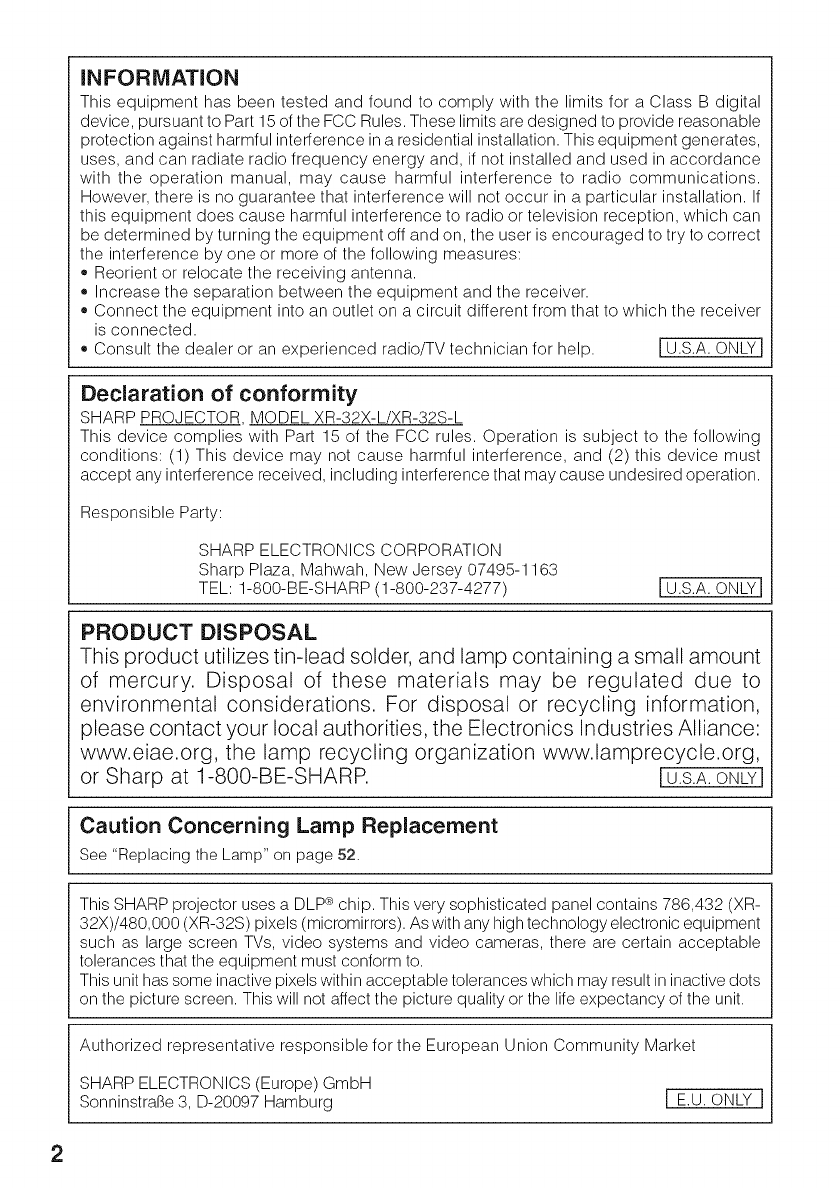
INFORMATION
This equipment has been tested and found to comply with the limits for a Class B digital
device, pursuant to Part 15 of the FCC Rules. These limits are designed to provide reasonable
protection against harmful interference in a residential installation. This equipment generates,
uses, and can radiate radio frequency energy and, if not installed and used in accordance
with the operation manual, may cause harmful interference to radio communications.
However, there is no guarantee that interference will not occur in a particular installation. If
this equipment does cause harmful interference to radio or television reception, which can
be determined by turning the equipment off and on, the user is encouraged to try to correct
the interference by one or more of the following measures:
,, Reorient or relocate the receiving antenna.
,, Increase the separation between the equipment and the receiver.
,, Connect the equipment into an outlet on a circuit different from that to which the receiver
is connected.
o Consult the dealer or an experienced radio/TV technician for help. I U.S.A. ONLY I
Declaration of conformity
SHARP PROJECTOR MODEL XR-32X-L/XR-32S-L
This device complies with Part 15 of the FCC rules. Operation is subject to the following
conditions: (1) This device may not cause harmful interference, and (2) this device must
accept any interference received, including interference that may cause undesired operation.
Responsible Party:
SHARP ELECTRONICS CORPORATION
Sharp Plaza, Mahwah, New Jersey 07495-1163
TEL: 1-800-BE-SHARP (1-800-237-4277) I U.S.A. ONLY I
PRODUCT DISPOSAL
This product utilizes tin-lead solder, and lamp containing a small amount
of mercury. Disposal of these materials may be regulated due to
environmental considerations. For disposal or recycling information,
please contact your local authorities, the Electronics Industries Alliance:
www.eiae.org, the lamp recycling organization www.lamprecycle.org,
or Sharp at 1-800-BE-SHARP. I U.S.A. ONLYJ
Caution Concerning Lamp Replacement
See "Replacing the Lamp" on page 52.
This SHARP projector uses a DLP ° chip. This very sophisticated panel contains 786,432 (XR-
32X)/480,000 (XR-32S) pixels (micromirrors). As with any high technology electronic equipment
such as large screen TVs, video systems and video cameras, there are certain acceptable
tolerances that the equipment must conform to.
This unit has some inactive pixels within acceptable tolerances which may result in inactive dots
on the picture screen. This will not affect the picture quality or the life expectancy of the unit.
Authorized representative responsible for the European Union Community Market
SHARP ELECTRONICS (Europe) GmbH
Sonninstral3e 3, D-20097 Hamburg [ E.U. ONLY I
2
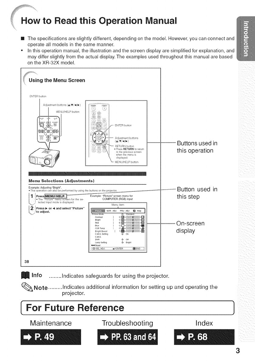
Read this Operation Manual
[] The specifications are slightly different, depending on the model. However, you can connect and
operate all models in the same manner.
,, In this operation manual, the illustration and the screen display are simplified for explanation, and
may differ slightly from the actual display. The examples used throughout this manual are based
on the XR-32X model.
Using the Menu Screen
ENTER button
Adjustment buttons (,L/T/_/_)
MENU/HELP button
to the previous screen
when the menu is
Mene Selections {Adjustments)
Example: Adiusting 'Bright'.
[ 0Q- _ ÷Q
B_u_ [ 0[-' l; +[
CLRTe_rp
8_ig_tBoost [1
CMS Se_4ng _ Or,
CMS
DN_ _ O_
LarrpSetting _ Bright
*.*Reset
,SEL/ADJ ._ ENTE_ []END
38
Info ........ Indicates safeguards for using the projector.
i i i_ii
!i_ iii i
iii !!i_
Buttons used in
this operation
..............Button used in
this step
On-screen
display
iiill _
iill
i i i i ii
ii iiii
%Note ......... Indicates additional information for setting up and operating the
projector.
[For Future Reference )
Mai nte nan ce Trou bles hooti ng Index
3
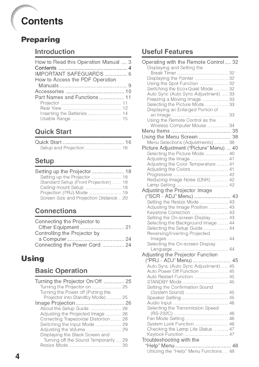
4
How to Road this Operation Manual .... 3
Contents ............................................... 4
IMPORTANT SAFEGUARDS ............... 6
How to Access the PDF Operation
Manuals .............................................. 9
Accessories ........................................ 10
Part Names and Functions ................. 11
Proiecl.or 11
Rear View ............................................ 12
Insertin0 the Batteries .......................... 14
Usable Range ...................................... 15
Quick Start
Quick Start .......................................... 16
Setup and Projoction ............................ 16
Setting up the Projector ...................... 18
Sett[n 0 up the Projector ...................... 18
Standard Setup (Front Projeclion) ....... 18
Ceilino-mounl Seup ............................ 18
Projection (PRJ) Mode ......................... 19
Screen Size and Projection Distance. 20
Connections
Connecting the Projector to
Other Equipment .............................. 21
Controlling the Projector by
a Computer ....................................... 24
Connecting the Power Cord ............... 24
Using
Basic Operation
Turning the Projector On/Off .............. 25
Turnin 0 the Projector on ................. ?5
rurnin 0 the Power or (Putt}n 0 the
Projector into SIandby Mode) ........... 25
Image Proiection ................................. 26
About the Seh_p Guide ............... ?6
AdjusIin 0 I:he Projected Image ........ ?6
Correctin 0 trapezoidal D}slort}on ........ 28
Switchin 0 the Input Mode .................... 29
Adjusdn 0 the VokJme .......................... 29
Displayin 0 the Black Screen and
Turnin 0 or the Sound q2_mporadly .... 29
Resize Mode ......................................... 30
Useful Features
Operating with the Remote Control .... 32
Display}n 0 and Sel:tin 0 the
Break Timer ....................................... 32
Display}n 0 the Pointer ......................... 32
Usin 0 the Spot Funclion ...................... 32
Switchin 0 the Eco+Quiet Mode .......... 32
Auto Sync (Auto Sync Adjustment) ..... 33
Freezin 0 a Movin 0 Image .................... 33
Select}n 0 I:he Piclure Mode .................. 33
Displayin 0 an Enlarged Port}on of
an Image .......................................... 33
Usin 0 the Remote Conlrol as the
Wireless Computer Mouse ................ 34
Menu Items ......................................... 35
Using the Menu Screen ...................... 38
Menu Seleol.ions (Adiustmer_ts) 38
Picture Adiustment ("Picture" Menu) ,,, 40
Selecting the Picl:ure Mode .................. 40
Adjustin 0 the Image ............................. 41
Adjustin 0 the Color Temperature ......... 41
Adjustin 9 the Colors ............................. 41
Prooressiw) 42
Reduc}n 0 Image Noiso (DNR) ............. 42
Lamp Setting ........................................ 42
Adjusting the Projector Image
('SCR - ADJ" Menu) ......................... 43
Sel:ting the Re_;i e Mode 3
Adjustin 0 the Ima0e Position 43
Keyslor_e Corroction ................... 43
Sel:tin 0 the On-screen Display ............. 43
Selectin 0 the Background Image ........ 44
Select}n 0 the Seh_p Guide ................... 44
Reversino/Invert}n 0 Projected
Images ............................................ 44
Selecting the On-screen Display
Lanoua0e ........................................... 44
Adjusting the Projector Function
('PRJ - ADJ" Menu) .......................... 45
Auto Sync (Auto Sync Adiustmenl.) 45
Auto Power Oil Function 45
Auto Restart Function .......................... 45
STANDBY Mode .................................. 45
Setin 0 the Confirmation Sound
(System Sound) ................................. 45
Speaker Setin 0 .................................... 45
Audio Input ...................................... 46
Select}n 0 the transmission Speed
(RS-232C) .......................................... 46
Fan Mode Settin 0 ............................... 46
Sysl:em Lock Function ......................... 46
Checking the Lamp Life Stal.us ........... 47
Keylock Function .................................. 47
Troubleshooting with the
"Help" Menu ...................................... 48
ULiE4ng the "Holp Monu Function,_; .... 48
Reference
Maintenance ....................................... 49
Maintenance Indicators ...................... 50
Regarding the Lamp ........................... 52
Lamp ................................................ 52
Caut}on Concerning the Lamp ............ 52
Replacing the Lamp ............................. 52
Removing and InstalJ}ng the
Lamp Unit .......................................... 53
Reseldng the Lamp Timer .................... 54
Connecting Pin Assignments ............. 55
RS-232C Specifications and
Commands ....................................... 57
Computer Compatibility Chart ............ 62
Troubleshooting .................................. 63
For SHARP Assistance ...................... 65
Specifications ..................................... 66
Dimensions ......................................... 67
Index ................................................... 68
i i i_ii
!i_ iii i
iii !!i_
iii ii_
i(ii
_!i_i!i_i
5

Mpo .TSAFEGUARDS
CAUTION" Pleasereada, oftheseinstructionsbeforeyouoperatethisproduct
and save these instructions for later use.
Electrical energy can perform many useful functions. This product has been engineered
and manufactured to assure your personal safety. BUT IMPROPER USE CAN RESULT IN
POTENTIAL ELECTRICAL SHOCK OR FIRE HAZARDS. In order not to defeat the
safeguards incorporated in this product, observe the following basic rules for its installation,
use and servicing.
1.
2.
3.
4.
5.
6=
7.
Read Instructions
All the safety and operating instructionsshould
be read before the product is operated.
Retain Instructions
The safety and operating instructions should be
retained for future reference.
Heed Warnings
All warnings on the product and inthe operating
instructions should be adhered to.
Follow instructions
All operating and use instructions should be
followed.
Cleaning
Unplug this product from the wall outlet before
cleaning. Do not use liquid cleaners or aerosol
cleaners. Use a damp cloth for cleaning.
Attachments
Donot useattachments not recommended by the
product manufacturer as they maycause hazards.
Water and Moisture
Do not use this product near water,or example,
near a bath tub, wash bowl, kitchen sink, or
laundry tub; in a wet basement; or near a
swimming pool; and the like.
Accessories
Do not place this product on an unstabb cart,
stand, tripod, bracket, or table. The product may
fall, causing serious injuryto a child or adult, and
serious damage to the product. Use only with a
cart, stand, tripod, bracket, or table
recommended by the manufacturer, or sold with
the product. Any mounting of the product should
follow the manufacturer's instructions, and should
use a mounting accessory recommended by the
manufacturer.
Transportation
A product and cart
combination should be
moved with care. Quick
stops, excessive force,
and uneven surfaces may
cause the product and cart
combination to overturn.
10. Ventilation
Slots and openings in the cabinet are provided
for ventilation to ensure reliable operation of the
product and to protect it from overheating, and
these openings must not be blocked or covered.
Theopenings should never be blocked by placing
the product on a bed, sofa, rug, or other similar
surface. This product should not be placed ina
built-in installation such as a bookcase or rack
unless proper ventilation is provided or the
manufacturer's instructions have been adhered
to.
11. Power Sources
This product should be operated only from the
type of power source indicated on the marking
label. If you are not sure of the type of power
supply to your home, consult your product dealer
or local power company. For products intended
to operate from battery power, or other sources,
refer to the operating instructions.
12. Grounding or Polarization
This product is provided with one of the following
types of plugs. If the plug should fail to fit into the
power outlet, please contact your electrician.
Do not defeat the safety purpose of the plug.
a. Two-wire type (mains) plug.
b. Three-wire grounding type (mains) plug with
a grounding terminal.
This plug will only fit into a grounding type
power outlet.
13. Power-Cord Protection
Power-supply cords should be routed sothat they
are not likely to be walked on or pinched by items
placed upon or against them, paying particular
attention to cords at plugs, convenience
receptacles, and the point where they exit from
the product.
14. Lightning
For added protection for this product during a
lightning storm, or when it is left unattended and
unused for long periods of time, unplug it from
the wall outlet and disconnect the cable system.
This will prevent damage to the product due to
lightning and power-line surges.
6
15. Overloading
Do not overload wall outlets, extension cords, or
integral convenience receptacles as this can
result in a risk of fire or electric shock.
16. Object and Liquid Entry
Never push objects of any kind into this product
through openings as they may touch dangerous
voltage points or short-out parts that could result
in a fire or electric shock. Never spill liquid of any
kind on the product.
17. Servicing
Donot attempt to service this product yourself as
opening or removing covers may expose you to
dangerous voltage or other hazards. Refer all
servicing to qualified service personnel.
18. Damage Requiring Service
Unplug this product from the wall outlet and refer
servicing to qualified service personnel under the
following conditions:
a. When the power-supply cord or plug is
damaged.
b. If liquidhasbeen spilled, or objects have fallen
intothe product.
c. If the product has been exposed to rain or
water.
d. If the product does not operate normally by
following the operating instructions.Adjust only
those controls that are covered by the
operating instructions, as an improper
adjustment of other controls may result in
damage and will often require extensive work
by a qualified technician to restore the product
to normal operation.
e. If the product has been dropped or damaged
inany way.
f. When the product exhibits a distinct change
in performance, this indicates a need for
service.
19. Replacement Parts
When replacement parts are required, be sure
the service technician has used replacement
parts specified by the manufacturer or have the
same characteristics as the original part.
Unauthorized substitutions may result in fire,
electric shock, or other hazards.
20. Safety Check
Upon completion of any service or repairs to this
product, ask the service technician to perform
safety checks to determine that the product is in
proper operating condition.
21. Wall or Ceiling Mounting
This product should be mounted to a wall or
ceiling only as recommended by the
manufacturer.
22. Heat
This product should be situated away from heat
sources such as radiators, heat registers, stoves,
or other products (including amplifiers) that
produce heat.
•DLP :'_and the DLP logo are registered trademarks of Texas Instruments.
•Microsoft <'')and Windowd ''_are registered trademarks of Microsoft Corporation in the United
States and/or other countries.
•PC/AT is a registered trademark of International Business Machines Corporation in the
United States.
•Adobe _'_Reade€ '_is a trademark of Adobe Systems Incorporated.
•MacintosM '_is a registered trademark of Apple Computer, Inc. in the United States and/or
other countries.
•All other company or product names are trademarks or registered trademarks of their
respective companies.
•Some IC chips in this product include confidential and/or trade secret property belonging
to Texas Instruments. Therefore you may not copy, modify, adapt, translate, distribute,
reverse engineer, reverse assemble or discompile the contents thereof.
!i!ii_ iii
7
Caution concerning the lamp unit
[] Potential hazard of glass par-
ticles if lamp ruptures. In case
of lamp rupture, contact your
nearest Sharp Authorized
Projector Dealer or Service
Center for replacement. [
See "Regarding the Lamp" on 2_;_',_&
PRt CAUCION
page 52. _Eo_u_,o_
Caution concerning the setup of the
projector
[] For minimal servicing and to maintain high
image quality, SHARP recommends that this
projector be installed in an area free from
humidity, dust and cigarette smoke. When the
projector is subjected to these environments,
the vents and lens must be cleaned more of-
ten. As long as the projector is regularly
cleaned, use in these environments will not
reduce the overall operation life of the unit.
Internal cleaning should only be performed
by a Sharp Authorized Projector Dealer or
Service Center.
Do not set up the projector in places
exposed to direct sunlight or bright light.
[] Position the screen so that it is not in direct
sunlight or room light. Light falling directly on
the screen washes out the colors, making
viewing difficult. Close the curtains and dim
the lights when setting up the screen in a
sunny or bright room.
Caution regarding placing of the projector
[] Place the projector on a level site within the
adjustment range (9 degrees) of the adjust-
ment foot.
[] After the projector is purchased, a faint smell
from the vent may appear when the power is
first turned on. This is normal and is not a
malfunction. It will disappear after the projec-
tor is used for a while.
When using the projector in high=altitude
areas such as mountains (at altitudes of
approximately 1,500 meters (4,900 feet)
or more)
[] When you use the projector in high-altitude
areas with thin air, set "Fan Mode" to "High".
Neglecting this can affect the longevity of the
optical system.
Warning about placing the projector in
a high position
[] When placing the projector in a high position,
make certain it is carefully secure to avoid
personal injury caused by the projector fall-
ing down.
Do not subject the projector to hard
impact and/or vibration.
[] Protect the lens so as not to hit or damage
the surface of the lens.
Rest your eyes occasionally.
[] Continuously watching the screen for long
hours will cause eye strain. Take regular
breaks to rest your eyes.
Avoid locations with extremes of
temperature.
[] The operating temperature of the projector is
from 41°F to 95°F (+5°C to +35°C).
[] The storage temperature of the projector is
from -4°F to 140°F (-20°C to +60°C).
Do not block the exhaust and intake
vents.
[] Allow at least 11 13/16inches (30 cm) of space
between the exhaust vent and the nearest
wall or obstruction.
[] Ensure that the intake vent and the exhaust
vent are not obstructed.
[] If the cooling fan becomes obstructed, a pro-
tection circuit will automatically put the pro-
jector into standby mode to prevent overheat
damage. This does not indicate a malfunc-
tion. (See pages 50 and 51 .) Remove the pro-
jector power cord from the wall outlet and wait
at least 10 minutes. Place the projector where
the intake and exhaust vents are not blocked,
plug the power cord back in and turn on the
projector. This will return the projector to the
normal operating condition.
8

Caution regarding usage of the projector
[] If you are not to use the projector for a long
time or before moving the projector, make
certain you unplug the power cord from the
wall outlet, and disconnect any other cables
connected to it.
[] If the power cord is unplugged while the cool-
ng fan is running, some parts of the projec-
[or may still be qot Use cautior when han-
dling the projector.
[] Do not carry the projector by holding the lens.
[] When storing the projector, ensure you at-
tach the lens cap to the projector. (See page
11.
[] Do not expose the projector to direct sunlight
or place next to heat sources. Doing so may
affect the cabinet color or cause deformation
of the plastic cover.
Other connected equipment
[] When connecting a computer or other audio-
visual equipment to the projector, make the
connections AFTER unplugging the power
cord of the projector from the AC outlet and
turning off the equipment to be connected.
[] Please read the operation manuals of the pro-
.ector and the equipment to be connected for
nstructions on how to make the connections.
Using the projector in other countries
[] The power supply voltage and the shape of
the plug may vary depending on the region
or country you are using the projector in.
When using the projector overseas, make
sure you use an appropriate power cord for
the country you are in.
Temperature monitor function
[] If the projector starts to overheat due to setup
problems or blockage of the air vents. "_" and
"_" will illuminate in the lower left corner
ol the picture, if the temperature continues to
rise. the lamp will turn off. the temperature warn-
_ngindicator on the projector will blink, and after
a 60-second cooling-off period the projector will
enter standby mode. Refer to "Maintenance In-
dicators" on page 50 for details.
Info
•The cooling fan regulates the interna tem-
perature, and its performance is automatically
controlled. The sound of the fan may change
during projector operation due to changes in
the fan speed.This does not indicate malfunc-
tion.
How to Access the PDF Operation Manuals
PDF operation manuals in several languages are included in the CD-ROM.To uti-
lize these manuals, you need to install Adobe ® Reader ® on your computer (Win=
dows ®or Macintosh®).
Please download Adobe -_Reader :_from the Internef (httD://www.adobe.coml.
Accessing the PDF Manuals for Windows _ (For Macintosh ®, skip step (_)).
1_ insert the CD-ROM in the CD-ROM drive. _6_ Double click the language name of the
._ Double click the "My Computer" icon. folder that you want to view.
Double click the "CD-ROM" drive. (_ Double click the pdf file to access the pro-
Double click the "MANUALS" folder, jector manuals.
Double click the model ,name of the folder,
that you want to view.
Note
_, if tne desirec odf file cannot be opened uy dOUUle CliCKing _ne mouse start Adobe ® Reader ® first
inert specify the desired file using the "File". "Coen' menu
9
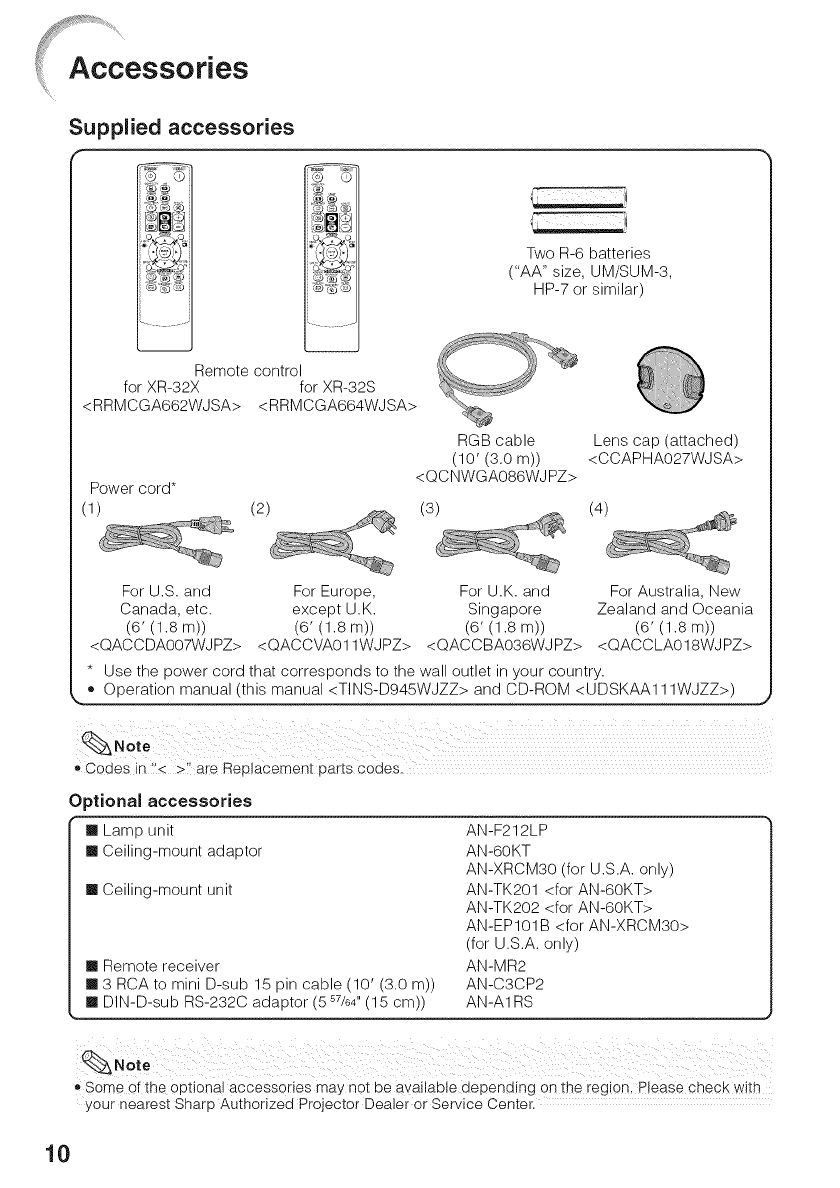
Supplied accessories
f
Remote control
for XR-32X for XR-32S
<RRMCGA662WJSA> <RRMCGA664WJSA>
Two R-6 batteries
("AA" size, UM/SUM-3,
HP-7 or similar)
RGB cable Lens cap (attached)
(10' (3.0 m)) <CCAPHA027WJSA>
Power cord* <QCNWGA086WJPZ>
(1) (2) (3) (4)
For U.S. and For Europe, For U.K. and For Australia, New
Canada, etc. except U.K. Singapore Zealand and Oceania
(6' (1.sm)) (6' (1.sm)) (6' (1.sm)) (6' (1.sm))
<QACCDA007WJPZ> <QACCVA011WJPZ> <QACCBA036WJPZ> <QACCLA018WJPZ>
* Use the power cord that corresponds to the wall outlet in your country.
Codes in "< >! are Replacement parts codes.
Optional accessories
[] Lamp unit
[] Ceiling-mount adaptor
[] Ceiling-mount unit
[] Remote receiver
[] 3 RCA to mini D-sub 15 pin cable (10' (3.0 m))
[] DIN-D-sub RS-232C adaptor (557/64'' (15 cm))
AN-F212LP
AN-60KT
AN-XRCM30 (for U.S.A. only)
AN-TK201 <for AN-60KT>
AN-TK202 <for AN-60KT>
AN-EP101B <for AN-XRCM30>
(for U.S.A. only)
AN-MR2
AN-C3CP2
AN-A1RS
_'Some Ofthe optional accessories may not be available depending on the region, P!ease check with
your nearest Sharp Authorized Projector Dealer or Service Center.
10
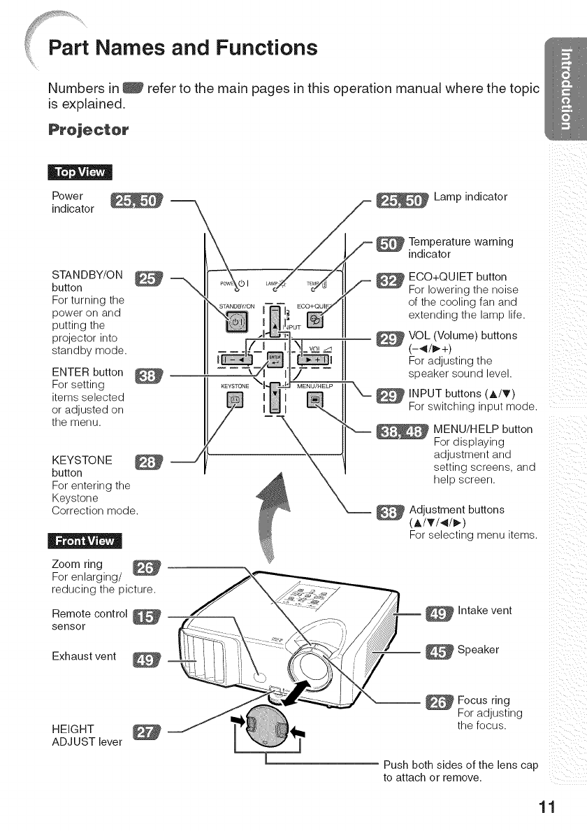
Part Names and Functions
Numbers in _ refer to the main pages in this operation manual where the topic
is explained.
Projector
Powe r
indicator \
STANDBY/ON
button
For turning the
power on and
putting the
projector into
standby mode.
ENTER button
For setting
items selected
or adjusted on
the menu.
KEYSTONE
button
For entering the
Keystone
Correction mode.
_ Lamp indicator
__S _ Temperature warning
indicator
EGO+QUIET button
A f _ For lowering the noise
of the cooling fan and
extending the lamp life.
VOL (Volume) buttons
(-_/_+)
For adjusting the
speaker sound level.
INPUT buttons (A/T)
For switching input mode.
MENU/HELP button
For displaying
adjustment and
setting screens, and
help screen.
Adjustment buttons
(At_'/_/_)
For selecting menu items.
Zoom ring
For enlarging/
reducing the picture.
Remote control
sensor Intake vent
Exhaust vent __ _ Speaker
HEIGHT
ADJUST lever
Focus ring
For adjusting
the focus.
Push both sides of the lens cap
to attach or remove.
/i!
_iiii/ i_
_ii_i_ii_
ii _ii: ii
ii i
iil ii
ii
/i _ii
11

Numbers in _ refer to the main pages in this operation manual where the topic
is explained.
Rear View
*AUDIO 1 input terminal ___
COMPUTER/
COMPONENT input
terminal
Terminal for computer RGB
and component signals.
*DVI-D input __
terminal
Terminal for
DVI digital RGB
and digital
component
signals.
*AUDIO OUT
terminal
Audio output terminal of
equipment connected to the
audio input terminal.
MONITOR OUT
terminal
(Output terminal for computer RGB,
component signals. Shared for COM-
PUTER/COMPONENT)
Terminal for connecting a monitor.
--_ S-VIDEO input terminal
Terminal for connecting
video equipment with an
S-video terminal.
--_ RS-232C terminal
Terminal for
controlling the
projector using a
computer.
--_ USB terminal
Terminal connecting
with the USB
terminal on the
computer for using
the supplied remote
control as the
computer mouse.
AUDIO 2 input
terminal
(AUDIO input
terminal for
XR-32S)
VIDEO input
terminal
Terminal for
connecting video
equipment.
* XR-32X only
Rear
adjustment
foot
AC socket
Connect the supplied
power cord.
Kensington Security
Standard connector
Using the Kensington Lock
o This projector has a Kensington Security Standard connector for use with a Kensington
MicroSaver Security System. Refer to the information that came with the system for
instructions on how to use it to secure the projector.
12

STANDBY button
For putting the projector
into the standby mode.
COMPUTER, *DVl,
S-VIDEO, VIDEO buttons
For switching to the
respective input modes.
BREAK TIMER button
For displaying the
break time.
MAGNIFY buttons
For enlarging/reducing
part of the image.
PAGE UP/PAGE
DOWN buttons
Same as the [Page Down] and
[Page Up] keys on a computer
keyboard, when with the USB
connection (using a USB cable
or the optional remote
receiver).
POINTER button
For displaying the
pointer.
MOUSE/Adjustment
buttons (A/T/4/I_) _
• For moving the
computer cursor when with the USB
connection (using a USB cable or the
optional remote receiver).
• For selecting and adjusting menu
items.
L-CLICK/EFFECT
button
• For the Left click
when with the USB connection
(using a USB cable or the optional
remote receiver).
• For changing the pointer or spot
area.
KEYSTONE button
For entering the
Keystone Correction mode.
AUTO SYNC button
For automatically
adjusting images when
connected to a computer.
ECO+QUIET button
For lowering the noise
of the cooling fan and
extending the lamp life.
ON button
For turning the power
on.
FREEZE button
For freezing images.
AV MUTE button
For tern porarily
displaying a black
screen and turning
off the sound.
VOL +/- (Volume)
buttons
For adjusting the
speaker sound level.
SPOT button
For displaying the
spotlight.
ENTER button
For setting items
selected or adjusted
on the menu.
R-CLICK/RETURN
_ button
•FortheRU,tc,ck
when with the USB
connection (using a
USB cable or the
optional remote
receiver),
• For returning to the
previous menu screen
during menu
operations,
_ MENU/HELP button
For displaying
adjustment and
setting screens, and
helpscreen.
_ RESIZE button
For switching the
picture size (NOR-
MAL, BORDER, etc.).
PICTURE MODE
button
For selecting the
appropriate picture.
* XR-32X only
13
Part Names and Functions (Continued)
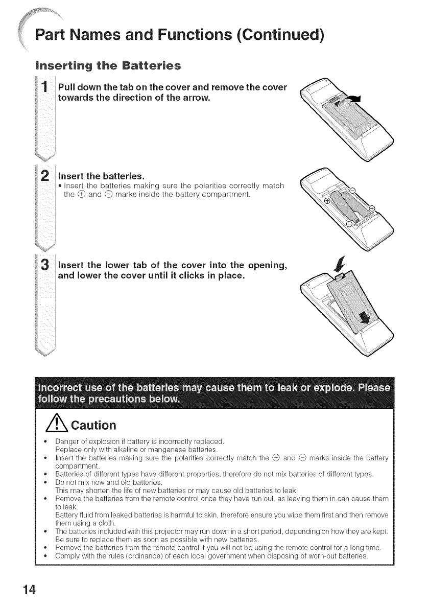
mnserting the Batteries
Pull down the tab on the cover and remove the cover
towards the direction of the arrow.
insert the batteries.
®Insert the batteries making sure the polarities correctly match
the (_ and (_ marks inside the battery compartment.
insert the tab of the cover into the opening,
I! the cover until it clicks in place.
/_ Caution
• Danger of explosion if battery is incorrectly replaced.
Replace only with alkaline or manganese batteries.
• Insert the batteries making sure the polarities correctly match the _ and _ marks inside the battery
compartment.
• Batteries of different types have different properties, therefore do not mix batteries of different types.
• Do not mix new and old batteries.
This may shorten the life of new batteries or may cause old batteries to leak.
,, Remove the batteries from the remote control once they have run out, as leaving them in can cause them
to leak.
Battery fluid from leaked batteries is harmful to skin, therefore ensure you wipe them first and then remove
them using a cloth.
• The batteries included with this projector may run down in a short period, depending on how they are kept.
Be sure to replace them as soon as possible with new batteries.
• Remove the batteries from the remote control if you will not be using the remote control for a long time.
• Comply with the rules (ordinance) of each local government when disposing of worn-out batteries.
14
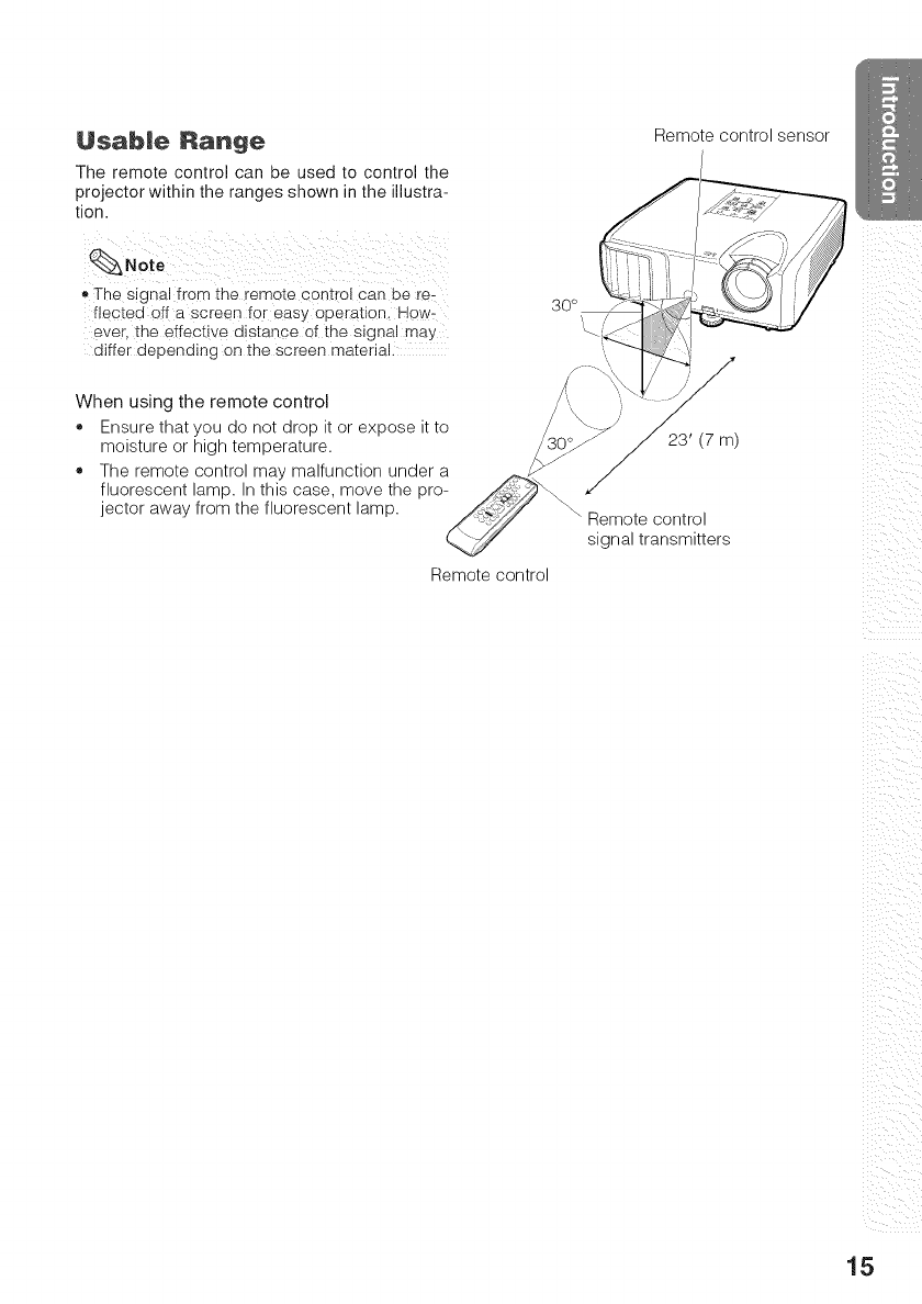
Usabme Range
The remote control can be used to control the
projector within the ranges shown in the illustra-
tion.
_,The signal from the remote cont[ot can be rex
fiected off a screen for easy operation, Hew:
ever, the effective distance of the signal may
differ depending on the screen material.
When using the remote control
.Ensure that you do not drop it or expose it to
moisture or high temperature.
*The remote control may malfunction under a
fluorescent lamp. In this case, move the pro-
jector away from the fluorescent lamp.
Remote control
Remote control sensor
23' (7 m)
Remote control
signal transmitters
ii_iii_i_ii_I__ii_
ill
iii i_i
ii ii
15
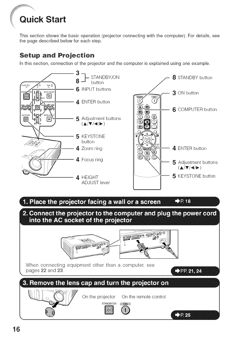
oui kstart
This section shows the basic operation (projector connecting with the computer). For details, see
the page described below for each step.
Setup and Prejeetion
in this section, connection of the projector and the computer is explained using one example.
3
8_ STANDBY/ON
button
6 INPUT buttons
4 ENTER button
-- 5 Adjustment buttons
(A/T/4/_)
5 KEYSTONE
button
4 Zoom ring
:::'_/ 4 Focus ring
)
4 HEIGHT
ADJUST lever
8 STANDBY button
._:0____ 3ON button
_-- 6 COMPUTER button
4 ENTER button
5 Adjustment buttons
(A/T/4/_)
-5KEYSTONE button
When connecting equipment other than a computer, see
pages 22 and 23.
On the projector On the remote control
STANDBY/ON
16
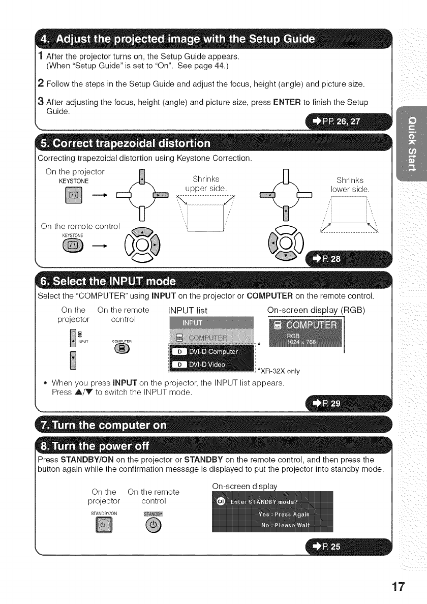
1 After the projector turns on, the Setup Guide appears.
(When "Setup Guide" is set to "On". See page 44.)
2 Follow the steps in the Setup Guide and adjust the focus, height (angle) and picture size.
3 After adjusting the focus, height (angle) and picture size, press ENTER to finish the Setup
Guide.
Correcting trapezoidal distortion using Keystone Correction.
ot e oecto+
KEYSTONE Shrinks
upper side.
On the remote control
Shrinks
lower side.
S-%
Select the "COMPUTER" using INPUT on the projector or COMPUTER on the remote control.
On the On the remote INPUT list
projector control
COMPUTER
®
On-screen display (RGB)
only
" When you press INPUT on the projector, the INPUT list appears.
Press A/Y to switch the INPUT mode.
Press STANDBY/ON on the projector or STANDBY on the remote control, and then press the
button again while the confirmation message is displayed to put the projector into standby mode.
On the On the remote
projector control
On-screen display
STANDBY/ON
.
/i _ii
17
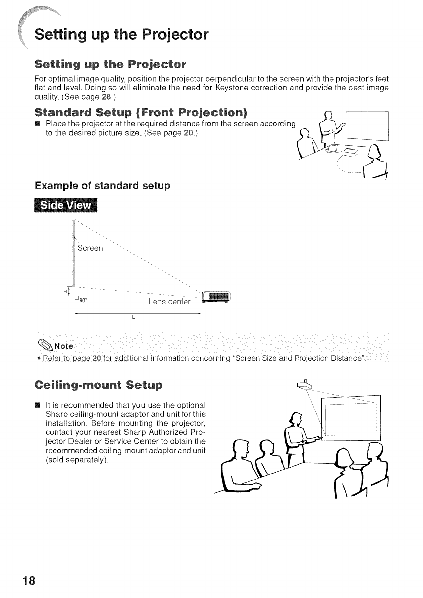
Setting up the Projector
Setting up the Projector
For optimal image quality, position the projector perpendicular to the screen with the projector's feet
flat and level. Doing so will eliminate the need for Keystone correction and _rovide the best image
quality. (See page 28.)
Standard Setup {Front Projection)
[] Place the projector at the required distance from the screen according
to the desired picture size. (See page 20.)
Example of standard setup
d
Screen -.
........... i
_9o° Lens cente
k
,, Refer to page 20 for additional information concerning ,Screen Size and Projection Distance'i,
Ceitingomount Setup
[] It is recommended that you use the optional
Sharp ceiling-mount adaptor and unit for this
installation. Before mounting the projector,
contact your nearest Sharp Authorized Pro-
jector Dealer or Service Center to obtain the
recommended ceiling-mount adaptor and unit
(sold separately).
18
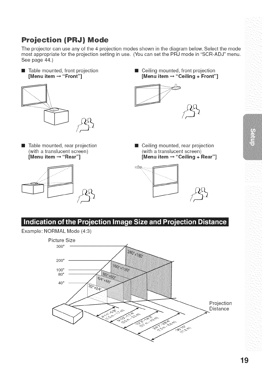
Prejectien {PRJ} Merle
The projector can use any of the 4 projection modes shown in the diagram below. Select the mode
most appropriate for the projection setting in use. (You can set the PRJ mode in "SCR-ADJ" menu.
See page 44.)
[] Table mounted, front projection
[Menu item -* "Front"]
[] Ceiling mounted, front projection
[Menu item -* "Ceiling + Front"]
[] Table mounted, rear projection
(with a translucent screen)
[Menu item _ "Rear"]
[] Ceiling mounted, rear projection
(with a translucent screen)
[Menu item -_ "Ceiling + Rear"]
Example: NORMAL Mode (4:3)
Picture Size
300"
Projection
Distance _iiiI __i_i
19
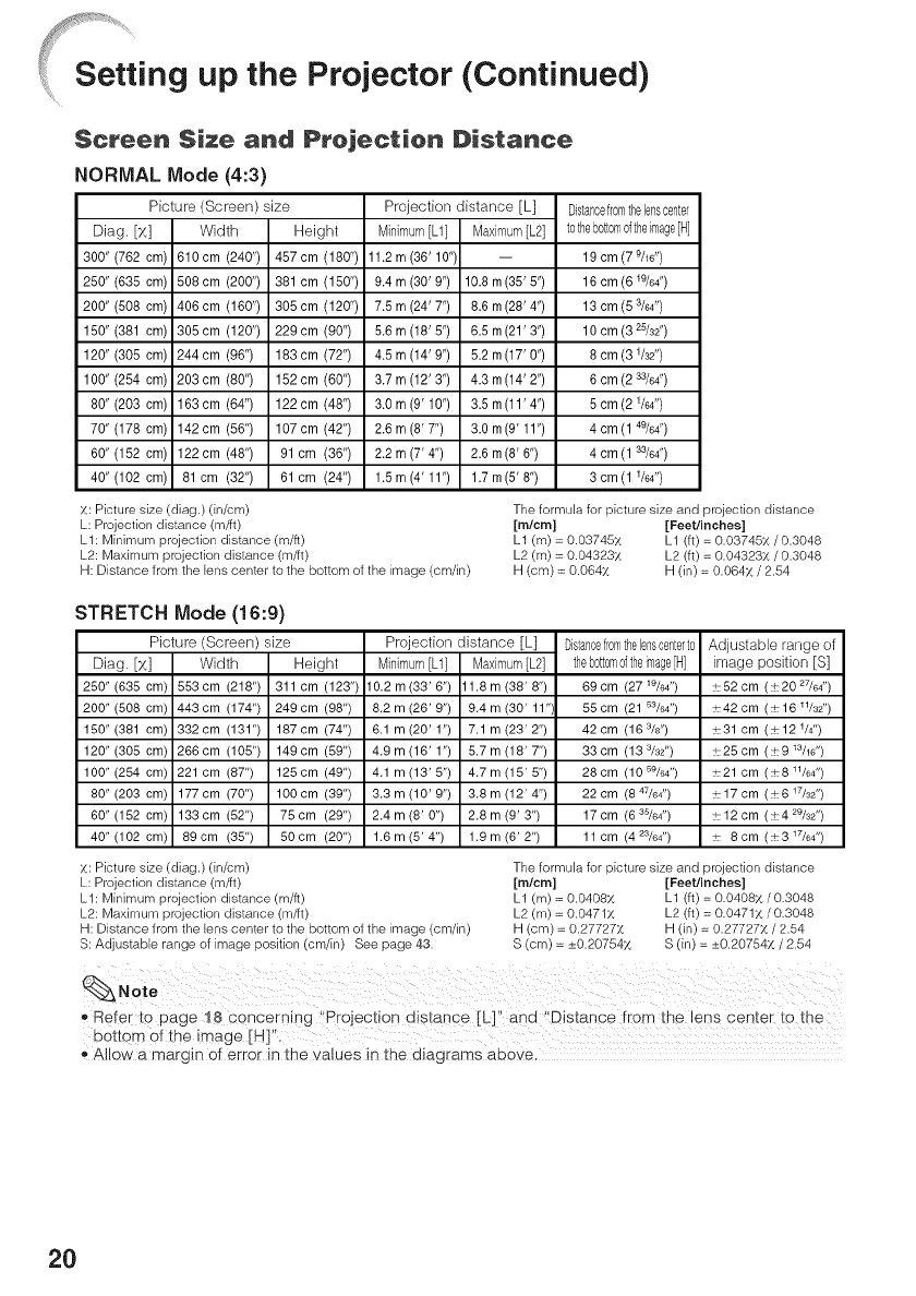
setting up the Projector (Continued)
$¢ree_ Size and Ptejectien Distance
NORMAL Mode (4:3)
Picture (Screen) size Projection distance [L] Distancefromthelenscenter
Diag. [x] Minimum [L1]
300" (762 cm) 11.2 m (36' 10")
250" (635 cm) 9.4 m (30' 9")
200" (508 cm) 7.5 rn (24' 7")
150" (381 cm) 5.6 rn (18' 5")
120" (305 cm) 4.5 rn (14' 9")
100" (254 cm) 3.7 m (12' 3")
80" (203 cm) 3.0 m (9' 10")
70" (178 cm) 2.6 rn (8' 7")
60" (152 cm) 2.2 m (7' 4")
40" (102 cm) 1.5 rn (4' 11")
x: Picture size (diag.) (in/cm)
L: Projection distance (m/ft)
LI: Minimum projection distance (m/fl)
L2: Maximum projection distance (m/ft)
H: Distance from the lens center to the bottom of the image (cm/in)
Width Height Maximum[L2] tothebottomoftheimage[H]
610 cm (240") 457 cm (180") -- 19 cm (7 _/16")
508cm (200") 381 cm (150") 10.8m(35'5") 16cm(6W64")
406cm (160") 305cm (120") 8.6m(28'4") 13cm(5%4")
305cm (120") 229cm (90") 6.5m(21'3") 10 cm (3 25/32")
244cm (96") 183cm (72") 5.2m(17' 0") 8 cm(31/32")
203cm (80") 152cm (60") 4.3 m(14' 2") 6 cm(2 _/64")
163cm (64") 122cm (48") 3.5 m(11'4") 5 cm(2 1/64")
142cm (56") 107cm (42") 3.0 m(9' 11") 4cm(1 49/64")
122cm (48") 91 cm (36") 2.6 m(8' 6") 4cm(1 _/64")
81 cm (32") 61 cm (24") 1.7m(5' 8") 3cm(1 1/64")
The formula for picture size and proiection distance
[micro] [Feet/inches]
L1 (m) = 0.03745X L1 (ft) = 0.03745X/0.3048
L2 (m) = 0.04323X L2 (ft) = 0.04323X /0.3048
H (cm) = 0.064x H (in) = 0.064x /2.54
STRETCH Mode (16:9)
Picture (Screen) size
Diag. [X]
250" (635 cm)
200" (508 cm)
150" (381 cm)
120" (305 cm)
100" (254 cm)
80" (203 cm)
60" (152 cm)
40" (102 cm)
X: Picture size (diag.) (in/cm)
L: Projection distance (m/ft)
LI: Minimum projection distance (m/fl)
L2: Maximum projection distance (m/ft)
H: Distance from the lens center to the bottom of the image (cm/in)
S: Adjustable range of image position (cm/in) See page 43.
Width Height
553cm (218") 311 cm (123")
443 cm (174") 249 cm (98")
332cm (131") 187cm (74")
266cm (105") 149cm (59")
221 cm (87") 125cm (49")
177cm (70") lOOcm (39")
133cm (52") 75cm (29")
89 cm (35") 50 cm (20")
Projection distance [L]
Minimum [L1] Maximum [L2]
10,2m(33'6") 1.8m(36'8")
8,2 m (26' 9") 9,4 m (30' 11")
6.1 m (20' 1") 7.1 m (23' 2")
4,9m(16'1") 5.7m(16'7")
4,1m(13'5") 4,7m(15'5")
3,3m(10'9") 3,8m(12'4")
2,4 m (6' 0") 2,8 m (9' 3")
1.6 m (6' 4") 1.9 m (6' 2")
Distancefromthe lenscenterto
thebottomof theimage[H]
69 cm (27 W64")
55 cm (21 53/c-,4")
42 cm (16 3Is')
33 cm (13 3/32")
28 cm (10 59/64")
22 cm (8 47/64")
17 cm (6 35/64")
11 cm (4 23/64")
Adjustable range of
image position [S]
:52 cm ( + 20 27/64")
:42 cm ( + 16 1V32")
:31 cm (+12 V4")
26 cm (+9 W16")
:21 cm (+8 W64")
17 cm ( + 6 17/32")
12 cm ( + 4 29/32")
8cm (+317/64 ")
The formula for picture size and projection distance
[micro] [Feet/inches]
L1 (m)= 0.0408X L1 (ft)= 0.0408X/0.3048
L2 (m) = 0.0471X L2 (ft) = 0.0471X /0.3048
H (cm) = 0.27727x
S (cm) = _+0.20754x
H (in) = 0.277277, /2.54
S (in) = +_0.207547, /2.54
,, Refer to page 78 concerning "Projection distance [L]" and '!Distance from the lens center to the
bottom of the image [H]".
_,Allow a margin o_error in the values in the diagrams above.
20
i!!9................................ .
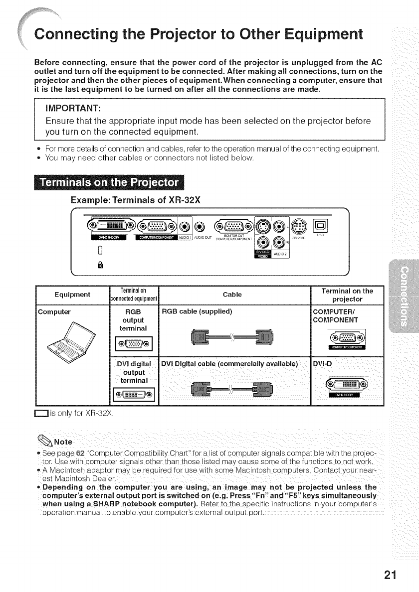
Connect|rig the Projector to Other Equipment
Before connecting, ensure that the power cord of the projector is unplugged from the AC
ouflet and turn off the equipment to be connected. After making all connections, turn on the
projector and then the other pieces of equipment. When connecting a computer, ensure that
it is the Jast equipment to be turned on after all the connections are made.
IIVIPORTANT:
Ensure that the appropriate input mode has been selected on the projector before
you turn on the connected equipment.
o For moredetailsof connectionand cables,referto theoperationmanualof theconnectingequipment.
o Youmay need other cables or connectors not listed below.
Example: Terminals of XR-32X
oo
Terminal0a
_'onnectedequipment
RGB
output
terminam
Cabme
RGB cabme (suppmied)
Terminam on the
projector
COMPUTER/
COMPONENT
Equipment
Computer
is or, for XR-32X.
Note
See page 62 "ComL)uter Compatibility Chart" for a list of computer s]gnats comuauule wltn the projec-
tor, use w_tn compufer s_gnaJs other tnan those listed ma /cause some of the functions to not work
®A Macintosh aaaDtor may De _eoutred for use with some Macimosn computers Contact your near-
es] Vlacintosh Dealer
Depending on the computer you are using, an image may not be projected unmess the
computer's external output port is switched on (e.g. Press "Fn" and "F5" keys simultaneously
when using a SHARP notebook computer). _efer to the suec fic qstructlons "- your compu[er s
ooeration manual to enable your computers external output uort.
21
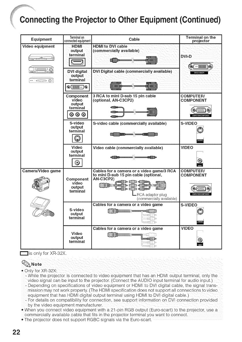
necting the Projectorto OtherEquipment(Continued)
Equipment
Video equipment
Camera/Video game
r""l is only for XR-32X.
Note
, Only for XR-32X:
Terminalon Terminam on the
connectedequipment Cabme projector
HDMI
output
terminal
terminal i =
18
Component
video
output
terminam
S-video
output
terminam
Video
output
terminam
Component
video
output
terminam
S-video
output
terminam
Video
output
terminam
3RCA to mini D-sub 15 pin cabme
(optional AN-C3CP2)
S-video cabme (commerciammy avaimabme)
Video cable (commerciammy available)
Cables for a camera or avideo game/3 RCA
to mini D-sub 15 pin cabme (optional
(commercially available)
Cables for a camera or a video game
Cabmes for a camera or a video game
COMPUTER/
COMPONENT
S-VIDEO
VIDEO
COMPUTER/
COMPONENT
S-VIDEO
VIDEO
- White the projector is connected to woeo eou_omen[ thai has an HDMI output terminal, only [ne
oeo signal can oe input to the projector. (Connec[ the AUDIO inout terminal for auolo Inuu[
- Deuenolng on specifications of video equipment or HDMI to DVt dic tal cable. [ne slcqa trans-
mission may no] WOrK properly, t The HDMI specification ooes r]o_ suuDort all connections to _ dec
equ pmen_ tna[ has HDMI digital cutout terminal uslnc HDMI to DV o_gltal cable.
- For details on compatibility for connec[ton, see SUDDOr[ _formation on DVI connec[_on Erowoeo
o:, the vloeo equ_pmen[ manufacturer.
®When you cot nect video eou_r0men[ wi_n a 21-oin RGB outou[ (Euro-scar_) _o _ne projector use a
cormercial _ available cab e that fits in the piojector term_na you Nant _o connecL
The projec[or ooes no_ support RGBC signals via the Euro-sca _
22
Equipment
Audio equipment
Nonitor RG8
input
terminal
Amplifier
03.5 mm
I '_ 'O1 audio inputo o o terminal
RCA audio
Terminalon Cable
;0nnectedequipment
e3.5 mm' o3,5 rnm Stereo or meno audio Cable
audio output (commercially available or available
RCA audio RCA audio cable (commercially available)
output
terminal
Cables for a camera or a video game
Audio
output
terminal
RGB cable (supplied or commercially
available)
Terminal on the
projector
AUDOi
IAUDIO2 (XR-32X)
IAUDIO (XR-32S)
MONITOR OUT
o3.5 mm stereo or mono audio cable
(commercially available or available
as Sharp service part QCNWGA038WJPZ)
=._======_//_ AUDIO OUT
o3.5 mm stereo minijack to RCA audio cable
(commercially available)
r-l is or _ for XR-32X.
_Note
Only for XR-32X:
- When using the o3.5 mm mono auaio cable. :he voJume level wdl be half of when using :he o3.5
mm stereo aua_o cable
- You can select "Aua_o 1" or "Audio 2" for "Audio Inout" in the "PRJ-ADJ" menu. :See page 45.'
RGB s gnals and Corr ponent s_gnals can De OUUDU::o me monitor.
23
,he
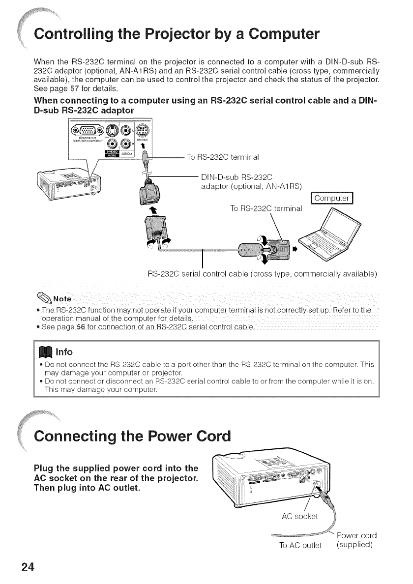
%Projector by a Computer
When the RS-232C terminal on the projector is connected to a computer with a DIN-D-sub RS-
232C adaptor (optional, AN-A1 RS) and an RS-232C serial control cable (cross type, commercially
available), the computer can be used to control the projector and check the status of the projector.
See page 57 for details.
When connecting to a computer using an RS=232C serial control cable and a DIN=
D=sub RS=232C adaptor
To RS-232C terminal
DIN-D-sub RS-232C
adaptor (optional, AN-A1RS)
To RS-232C terminal
I Computer I
RS-232C serial control cable (cross type, commercially available)
_,The RS-232C function may net operate it your computer terminal is not correctly set up. Refer to the
operation manua! of the computer for details
_,See page 56 for connection of an RS_232C serial control cable.
Info
,, Do not connect the RS-232C cable to a port other than the RS-232C terminal on the computer. This
may damage your computer or projector.
,, Do not connect or disconnect an RS-232C serial control cable to or from the computer while it is on.
This may damage your computer.
4onnecting the Power Cord
Plug the supplied power cord into the
AC socket on the rear of the projector.
Then plug into AC outlet.
Power cord
To AC outlet (supplied)
24
Turning the Projector On/Off
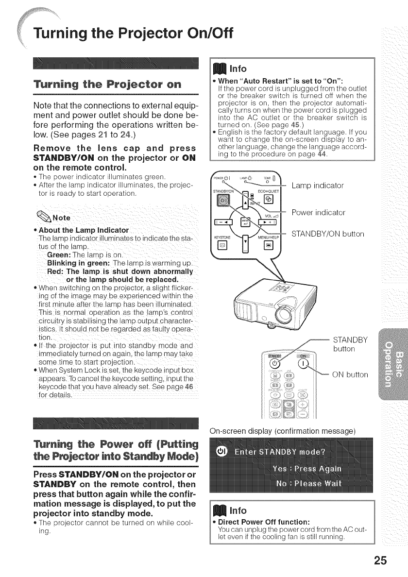
_rriing the Prejecter en
Note that the connections to external equip-
ment and power outlet should be done be-
fore performing the operations written be-
low. (See pages 21 to 24.)
Remove the lens cap and press
STANDBY/ON on the projector or ON
on the remote control
• The 9ower ind_ca;or mumma]es #reer
- After _ne lamo indicator umlnates tne projec-
[or Is ready to start operation
Note
•About the Lamp Indicator
The lamp indicator illummates to inalcate me sta-
tus of the _amp
Green: The lamp is on.
Blinking in green: The lamp is warming UD
Red: The Jamp is shut down abnormally
or the lara pshould be replaced.
• When swi[cnmg on me projec[or, a slic qt flicker-
ing of the image may De experienced within IRe
first mmute after the lamp nas Deen Jmma[ed.
Th s Is qormal oDerauon as [ne lamps con[rol
clrcul[r_ IS StaDlllslng IRe lamD QUIDU[ cnarac[e r-
Isttcs. Hsnou d not be regarded as faulty opera-
lion.
• ifthe orojector_s put intostandby mode and
_nmeo_a[eb Turned on again, me tamp may taKe
some lime to star]: pr Djeotton.
When Sys[em Lock is set, me Keycode InOU_DOX
appears. To cancel the keycode setting, _nput the
Keycode [nat you have already set. See page 46
for deta _s
Turnincj the Pewer e# {Putting
the P_jecter inte Standby Merle)
Press STANDBY/ON on the projector or
STANDBY on the remote control, then
press that button again while the confiP
marion message is displayed, to put the
projector into standby mode.
®The projector cannot be turned on while cool-
ing
Info
When "Auto Restart" is set to "On":
If the power cord is unplugged from the outlet
or the breaker switch is turned off when the
projector is on, then the projector automati-
cally turns on when the power cord is plugged
into the AC outlet or the breaker switch is
turned on. (See page 45.)
English is the factory default language. If you
want to change the on-screen display to an-
other language, change the language accord-
ing to the procedure on page 44.
STANDBY/ON _ ECO+QUIE]
Lamp indicator
Power indicator
STANDBY/ON button
STANDBY
_. ............... button
_) _?i:_ _ ON button
: f; 7/.
::s 4::2
On-screen display (confirmation message)
Info
.Direct Power Off function:
You can unplug the power cord from the AC out-
let even if the cooling fan is still running.
ii Li
!i_ iii i
iii !!i_
/i!
D_
D_
25
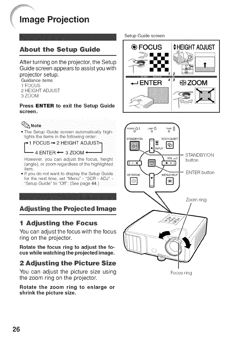
Abeut the Setup Guide
After turning on the projector, the Setup
Guide screen appears to assist you with
projector setup.
Guidance items
1 FOCUS
2 HEIGHT ADJUST
3ZOOM
Press ENTC:R to exit the Setup Guide
screen.
_Note
o The Setuo Guiue screen automatlcaliy nlg n-
ttgn[s [re items in the following eraer:
C FOCUS'_ 2 HEIGHT ADJUSTq.I
4 ENTER _== 3 ZOOM
However. you can aojus[ _ne _ocus, heighl
angle or zoom regardless of the highlighted
item.
• If you do not want to display the Setup Guide
for _ne next time. set "Menu" - SCR - ADJ" -
Setup Guide" to "Off". (See page 44.)
Adjusting the Projected image
tAdjusting the Fetus
You can adjust the focus with the focus
ring on the projector.
Rotate the focus ring to adjust the fo-
cus while watching the projected image.
2Adjusting the Picture Size
You can adjust the picture size using
the zoom ring on the projector.
Rotate the zoom ring to enlarge or
shrink the picture size.
Setup Guide screen
FOCUS _ ÷HEIGHTADJUST
STANDBY/ON
button
ENTER button
Zoom ring
Focus ring
26
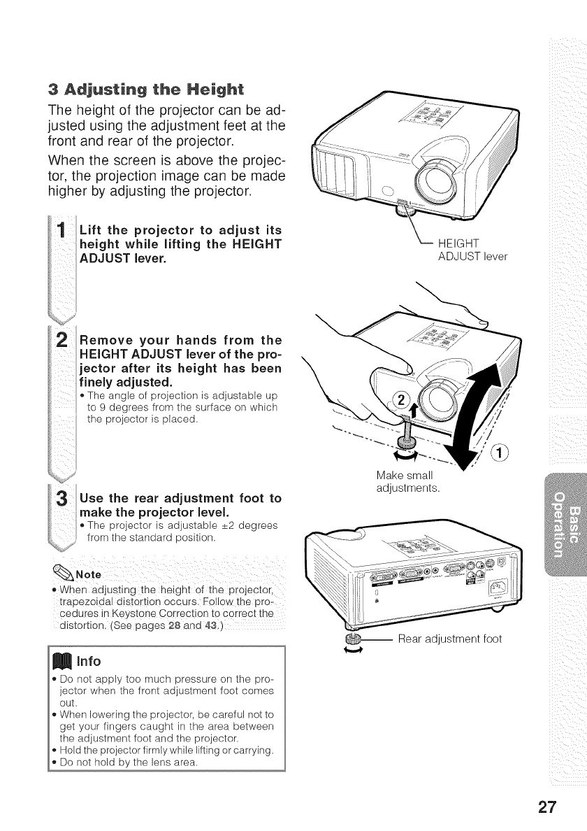
3 Adjusting the Height
The height of the projector can be ad-
justed using the adjustment feet at the
front and rear of the projector.
When the screen is above the projec-
tor, the projection image can be made
higher by adjusting the projector.
Lift the projector to adjust its
height while lifting the HEIGHT
ADJUST lever.
Remove your hands from the
HEIGHT ADJUST lever of the pro=
jector after its height has been
[inely adjusted.
The angle of projection is adjustable up
to 9 degrees from the surface on which
the projector is placed=
Use the rear adjustment foot to
make the projector level.
Theproieetoris adjustable_+2degrees
from the standard position.
,,When adjusting the height of the projector,
trapezoidal distortion occurs. Follo_ the pro-
cedures in Keystone Correction to correct the
distortion, (See pages 28 and 83,)
Info
Do not apply too much pressure on the pro-
jector when the front adjustment foot comes
out,
When lowering the projector, be careful not to
get your fingers caught in the area between
the adjustment foot and the projector=
Hold the projector firmly while lifting or carrying,
Do not hold by the lens area,
HEIGHT
ADJUST lever
Make small
adjustments.
_-- Rear adjustment foot
i i i_ii
iii !!i_
UI i_
i i
ill
27
[image Projection (Continued)
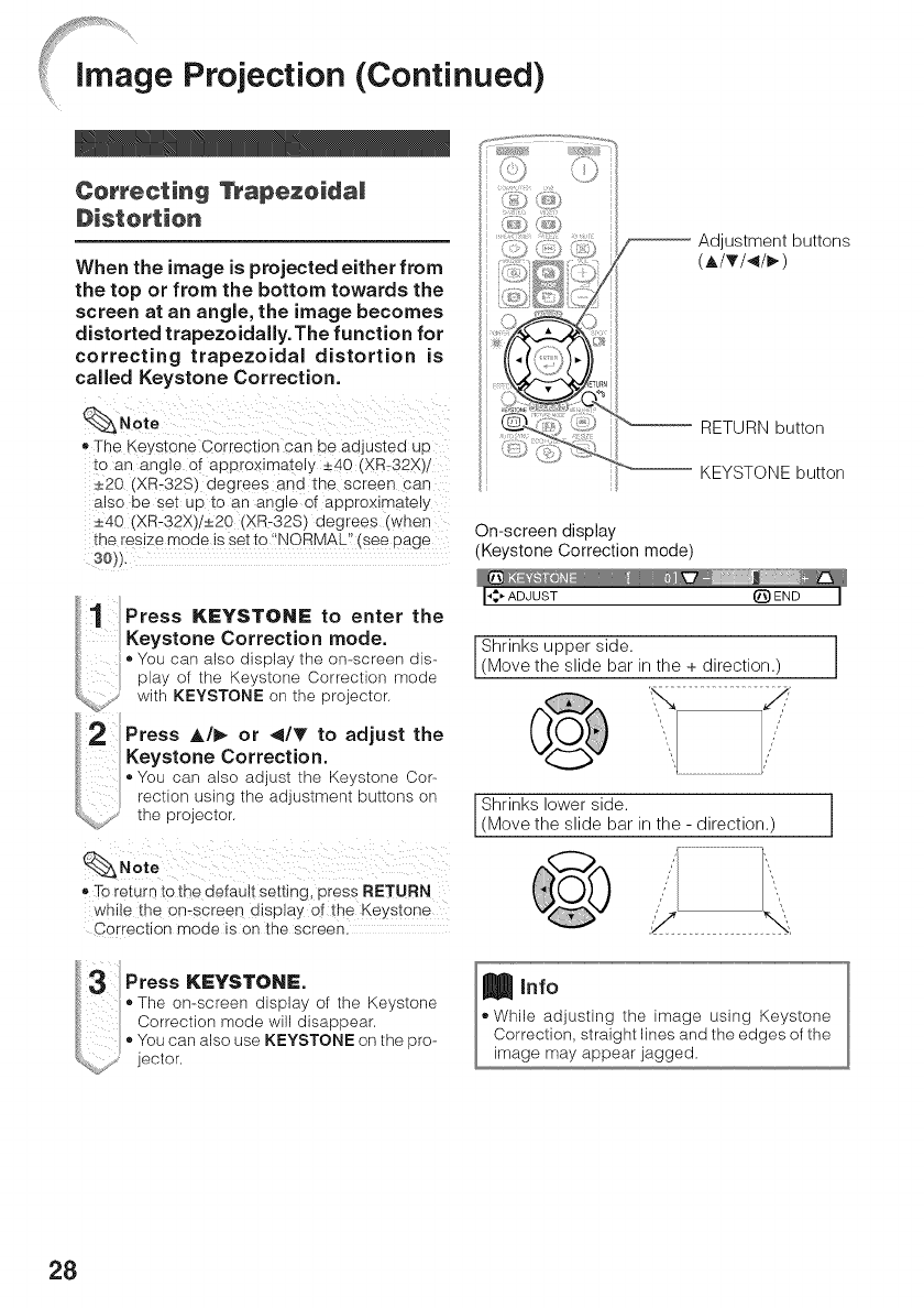
Correcting lntapezeidai
Distortion
When the image is projected either from
the top or from the bottom towards the
screen at an angle, the image becomes
distorted trapezoidally.The function for
correcting trapezoidal distortion is
called Keystone Correction.
_Note
e The Keystone Correction can De acijusteci u[._
to an ang e of approximately _+40 (XR-32X_
_+20 (XR-32S) degrees aria [ne screer- can
a so be set uo to an ang eof approximately
•+40 (XR-32X)/_+20 (XR-32S) degrees (when
the resize mode is setto "NORMAL" [see page
30_J.
Adjustment buttons
(AITI<I_)
KEYSTONE button
On-screen display
(Keystone Correction mode)
Press KEYSTONE to enter the
Keystone Correction mode.
•You can also display the on-screen dis-
play of the Keystone Correction mode
with KEYSTONE on the projector.
Press A/_ or <IT to adjust the
Keystone Correction.
•You can also adjust the Keystone Cor-
rection using the adjustment buttons on
the projector.
Shrinks upper side.
(Move the slide bar in the + direction.
Shrinks lower side.
(Move the slide bar in the - direction.)
•To return tOthe default setting, press RETURN
while !he omscreen display of the Keystone
Correction mode is on the screen.
Press KEYSTONE.
•The on-screen display of the Keystone
Correction mode will disappear.
•You can also use KEYSTONE on the pro-
jector.
Info
.While adj01sting the image using Keystone
Correction, straight lines and the edges of the
image may appear jagged.
28
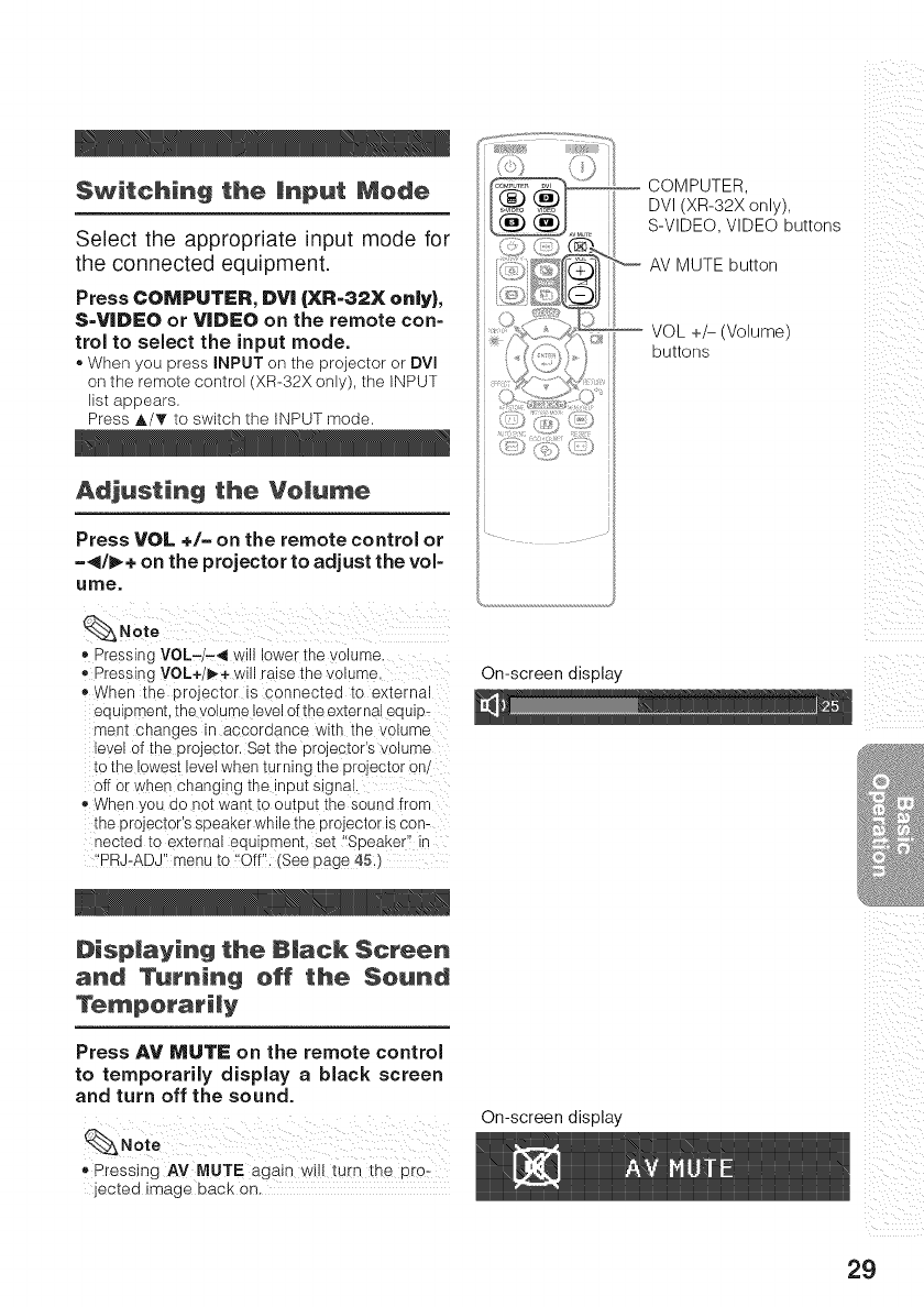
Switching the mnput Mode
Select the appropriate input mode for
the connected equipment.
Press COMPUTER, DV| (XR-82X only),
S-VIDEO or VIDEO on the remote con-
trol to select the input mode.
®When you press INPUT on the projector or DVl
on the remote control (XR-32X only), the INPUT
list appears.
Press A/T to switch the INPUT mode,
Adjusting the Vemu_e
Press VOL ÷/= on the remote control or
-</1_÷ on the projector to adjust the vol-
ume.
•Pressing VOL-/-<I will lower the volume ..................
• Pressing VOL+/I_÷ will raise the volume,
When the projector is connected to external
equipment, the volume level o[ the exter na!equip_
ment changes in accordance with the volume
level of the projector.Set the projectoCs volume
to the lowest level when turning the project0[ 0n/
off or when changing the !nput signal,
When you do not want to output the sound from
the projector's speakerwhilethe projector iscon-
nected to external equipment, set '!Speaker'! in
I!PRJ-ADJIImenu to {!Offi!i(See page 451)
Dispmaying the 8|ack Screen
and Tam'niricj off the Sound
Press AV MUTE on the remote control
to temporarily display a black screen
and turn off the sound.
Noto
,Pressing AV MUTE again Wilt turn ihe PrO
jected image back on.
COMPUTER,
DVI (XR-32X only),
S-VIDEO, VIDEO buttons
'_ AV MUTE button
VOL +/- (Volume)
buttons
ii i_I_ _i
!i_ iii i
iii !!i_
On-screen display
®
On-screen display
29
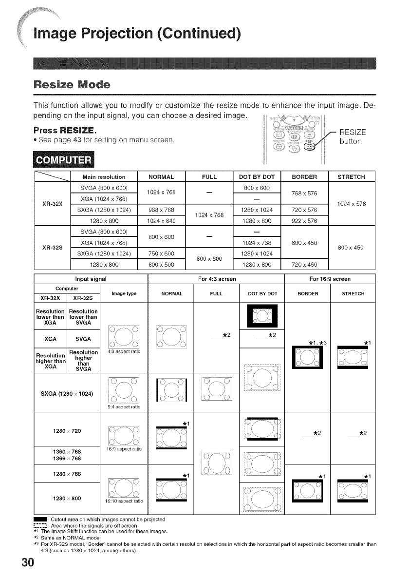
Image Projection (Continued)
Nesize Nede
This function allows you to modify or customize the resize mode to enhance the input image. De-
pending on the input signal, you can choose a desired image.
Press RESiZI=. RESIZE
®See page 43 for setting on menu screen, button
STRETCH
XR-32X
XR-32S
Main resolution
SVGA (800 x 600)
XGA (1024 x 768)
SXGA (1280 x 1024)
1280 x 800
SVGA (800 x 600)
XGA (1024 x 768)
SXGA (1280 x 1024)
1280 x 800
NORMAL
1024 x 768
968 x 768
1024 x 640
800 x 600
750 x 600
800 x 500
FULL
1024 x 768
800x 600
DOT BY DOT
800 x 600
1280 x 1024
1280 x 800
1024 x 768
1280 x 1024
1280 x 800
BORDER
768 x 576
720 x 576
922 x 576
600 x 450
720 x 450
Input signal For 4:3 screen
Computer Image type NORMAL FULL DOT BY DOT
XR-32X XR-32S
1024 x 576
800 x 480
Resolution Resolution
lower than lower than
XGA SVGA
XGA SVGA
Resolution
Resolution higher
higher than than
XGA SVGA
SXGA (1280 x 1024)
1280 x 720
1360 x 768
1366 x 768
1280 x 768
1280 x 800
4:3 aspect ratio
5:4 aspect ratio
16:9 aspect ratio
16:10 aspect ratio
: Cutout area on which images cannot be projected
:"";;'! : Area where the signals are off screen
.1 The Image Shift function can be used for these images.
.2 Same as NORMAL mode.
o/_o
"kl
"kl
"k2 "k2
For16:9 screen
BORDER STRETCH
.1,.3
.2 .2
.1
.1
.1
*s For XR-32S model, "Border" cannot be selected with certain resolution selections in which the horizontal part of aspect ratio becomes smaller than
4:3 (such as 1280 x 1024, among others)•
30
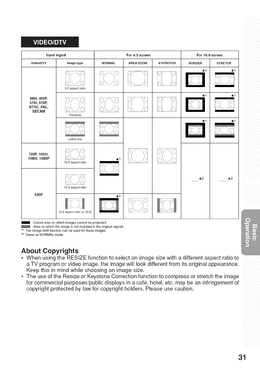
Input signal
Video/DTV Image type
4:3 aspect ratio
4801,480P,
576L 576P,
NTSC, PAL,
SECAM
Squeeze
Letter box
720P, 1035I,
1080I, 1080P
16:9 aspect ratio
16:9 aspect ratio
540P
(4:3 aspect ratio in 16:9)
For 4:3 screen
NORMAL AREA ZOOM V-STRETCH
i i }
,o\-)o
For 16:9 screen
BORDER STRETCH
_2 _2
: Cutout area on which images cannot be projected
: Area on which the image is not included in the original signals
*_ The Image Shift function can be used for these images.
.2 Same as NORMAL mode.
About Copyrights
. When using the RESlZE function to select an image size with a different aspect ratio to
a TV program or video image, the image will look different from its original appearance.
Keep this in mind while choosing an image size.
.The use of the Resize or Keystone Correction function to compress or stretch the image
for commercial purposes/public displays in a care, hotel, etc. may be an infringement of
copyright protected by law for copyright holders. Please use caution.
31
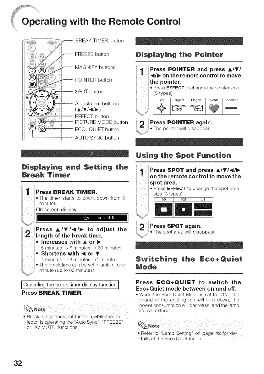
_Op_erating with the Remote Control
_i_i_..... iiiii¸_:_?_, BREAK TIMER button
FREEZE button
MAGNIFY buttons
POINTER button
SPOT button
Adjustment buttons
(A/T/</_)
EFFECT button
PICTURE MODE button
ECO+QUIET button
AUTO SYNC button
Disp|aying and Setting the
Break Timer
Press BREAK TIMER.
•The timer starts to count down from 5
minutes.
On-screen display
Dispmaying the Pointer
Press POINTER and press A/T/
</1_ on the remote control to move
the pointer.
•Press EFFECT to change the pointer icon
(5 types).
Press POINTER again.
•The pointer will disappear.
U!sing the Spot Furlcl_ien
Press SPOT and press A/T/</_
on the remote control to move the
spot area.
•Press EFFECT to change the spot area
size (3 types).
Press A/T/</_ to adjust the
length of the break time.
,, Increases with A or
5 minutes _ 6 minutes _ 60 minutes
• Shortens with < or _'
4 minutes _ 3 minutes _1 minute
•The break time can be set in units of one
minute (up to 60 minutes)=
I Canceling the break timer display function I
Press BREA_ TI_ER.
,, B_eak T!mer does not functio n while the pro-
jector is operating the ,Auto Sync" '!EREEZEI
or I!AVMUTE" functions,
Press SPOT again.
.The spot area will disappear.
$witchi_ the _ceeQ_iel:
_ode
Press ECO+QUIET to switch the
Eco+Quiet mode between on and off.
,, When the Eco+Quiet Mode is set to "ON". the
sound of the cooling fan will turn down. the
power consumption will decrease, and the lamp
life will extend.
_, Refer to 'iLamp Setting' on page 42 for de_
tans of the Eco÷Quiet mode.
32
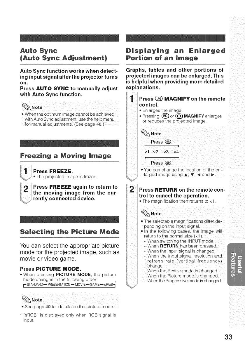
Auto Sync
{Auto Sync Adjustment)
Auto Sync function works when detect-
ing input signal after the projector turns
on.
Press AUTO SYNC to manually adjust
with Auto Sync function.
,, When the optimum image cannot be achieyed
with Auto Sync adjustment, use the help menu
for manual adjustments. (See page 48.)
Freezing a Moving !triage
il i
1 PressFREEZE.
_', The projected mage is frozen
2PressFREEZEagaintoreturnto
the moving image from the cur=
_j_: rently connected device.
Selecting the Picture Mode
You can select the appropriate picture
mode for the projected image, such as
movie or video game,
Press PICTURE MODE.
®VVhen pressing PICTURE MODE, the picture
mode changes in the following order:
r STANDARD_ PRESENTATION=._MOVIE--_GAME_ sRGB
Disp|aying an En|arged
Portion ef an !triage
Graphs, tables and other portions of
projected images can be enlarged.This
is helpful when providing more detailed
explanations.
1Press _ MAGNIFY on the remote
control.
-Enlarges tne image
-Pressing (_ or (_) MAGNIFY enlaroes
or reduces [ne projected mage
_Note
Press Q.
|
xl x2 x3 x4
(
Press (_).
,, You can change me location of the en-
largea image using A, T, <and I_
2Press RETURN on the remote con-
trol to cancel the operation.
-The magniticatior tner returns to xl.
_Note
_,The seiectable magnifications differ de-
penalng on the input signal
,, ,_ the following cases the Image w,
re[urn to me normal size _×1 "L
- When switchlnc the INPUT mode
- Wher" RETURN has been Dressed.
- When the nout signal is changed.
- When the input s gnal resolution and
refresn rate (vertical frequency)
cnange.
- When the Resize mode i_ cnangea
- When the P cture mode is changed.
- When the Progressive mode is changed.
_,See page 40 for details on the picture mode.
.... sRGB" is displayed only when RGB signal is
input.
33
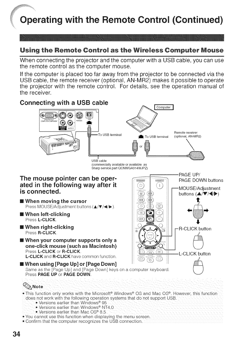
Oprating with the Remote Control (Continued)
When connecting the projector and the computer with a USB cable, you can use
the remote control as the computer mouse.
If the computer is placed too far away from the projector to be connected via the
USB cable, the remote receiver (optional, AN-MR2) makes it possible to operate
the projector with the remote control. For details, see the operation manual of
the receiver.
Connecting with a USB cable
--To USB terminal
--t
USB cable
(commercially available or available as
Sharp service part QCNWGA014WJPZ)
The mouse pointer can be oper-
ated in the following way after it
is connected.
[] When moving the cursor
Press MOUSE/Adjustment buttons (A/_'/</I_)
[] When left-clicking
PressL-CLICK,
[] When right-clicking
Press R-CLICK.
[] When your computer supports only a
one-click mouse (such as Macintosh)
Press L-CLICK or R-CLICK
L-CLICK and R-CLICK have common function. [
PAGE UP/
PAGE DOWN buttons
MOU SE/Adjustment
buttons (A/Y/_)
[] When using [Page Up] or [Page Down]
Same as the [Page Up] and [Page Down] keys on a computer keyboard.
Press PAGE UP or PAGE DOWN.
_,This function only works with the Mic_osott_>Windows ® OS and Mac OS®.However, this function
does not work with the fo!lowing operation systems that do not support USB.
®
_, Versions earlier than Windews_ 95
• ®
Versions earlier than Windows _ NT4,0
• ®
Versions earlier than Mac OS_ 8.5
_,You cannot use this function when displaying the menu screen.
Confirm that the computer recognizes the USB connection.
34
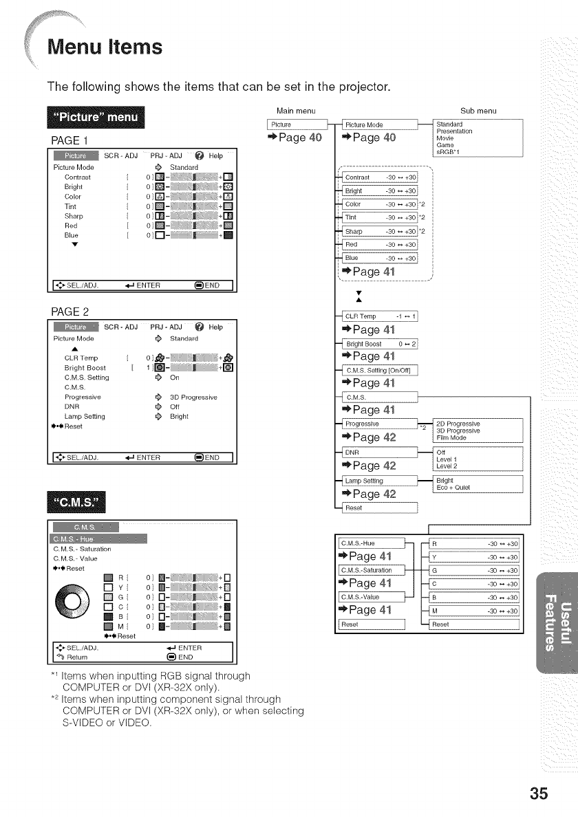
items
The following shows the items that can be set in the projector.
Main menu
Picture
'*Page 40
PAGE 1
SOR-ADJPRJ-ADJ@ Help
Picture Mode @ Standard
ConTr_st 0;[] +Q
Bright 01 +B']
color +D
Sharp 01[]- +_
Red O]D-:: _ + []
Blue 0 ] r-l- + []
I_*SEL.iADJ. "_JENTER (_)END I
PAGE2
SO.-ADJ p.J-ADJ @ Belp
Picture Mode _ Standard
c_Temp [oL_- Jlii: +_
Bright Boost [ 11[]- _ +1_'1
C.M,S, Setting _ On
C,M.S,
Progressive _ 3D Progressive
DNR ¢ Off
Lamp Setting _ Bright
II'._ Reset
I%% SEL/ADJ, _ ENTER _END I
o_ _: +D
o; 8- _M :+B
o_D- _ +D
el FI-::: J_ :+B
o; la- j +B
"_-IENTER I
_)END
*_ Items when inputting RGB signal through
COMPUTER or DVI (XR-32X only).
.2 Items when inputting component signal through
_{ Picture Mode
"*Page 40
Sub menu
_ Standard
Presentation
Movie
Game
sRGBH
_Con_r_s_-30_÷30j
Bright -30 _ +30j
Color -30 _ +30]_2
%i ............................................._2
Sharp -30 _ +30]_2
Red -30 _ +30]
Blue -30 _ +30]
,_Page 41 .,
2_ !_,,_................................
"*Page 41
Bright Boost 0 _ 2 I
"*Page 41
"* Page 41
C.M.S.
"*Page 41
Progressive
"* Page 42
_FDNR
"*Page 42
_L Lamp Setting
"*Page 42
Reset
j_.-_2D Progressive
3D Progressive
Film Mode
Level1
Level2
_ BdghtEco + Quiet
]
I
COMPUTER or DVI (XR-32X only), or when selecting
S-VIDEO or VIDEO.
i %
iI i
ii :_ii
35
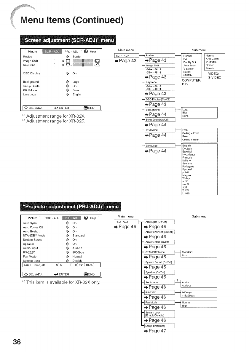
Menu items (Continued)
Picture _ PRJ- ADJ _ Help
Resize _ Border
Image Shift I 0][]-_; :1 J " _ _: +[]
Keystone [ 0]_- _ J +/_
OSD Display _ On
Background _ Logo
Setup Guide _ On
PRJ Mode _ Front
Language _ English
J _ SELJADJ, _ ENTER _ END
*3 Adjustment range for XR-32X.
.4 Adjustment range for XR-32S.
Main menu
_Page 43
Sub menu
,_Page43 . I[_;BYD°t I
"image Shirt
_!_rn VIDEO/
,_ Page 43 S-VIDEO
COMPUTER/
Keystone DTV
-40 _ +4°
,_ Page 43
-LosD_p_ tO_OB_J
,_ Page 43 ]
,_ Page 44
PRJ Mode }-i Front
Ceiling + Front
•,_Page 44 Rear
Ceiling + Rear
Language ]-- English
DeL_sch
._ Page 44 Esp_ho_
lederlands
_&nq&is
aliano
;venska
portugu_s
'VCCK{4_
_oIski
Aagyar
TQrkce
Picture SCR-ADJ _ _ Help
Auto Syr_c _ On
Main menu
PRJ - ADJ
,_.Page 45
Auto Power Off _ On
Auto Restart _ On
STANDBY Mode _ Standard
System Sound _ On
Speaker _ On
Audio Input _ Audio 1
RS-2320 _ 9600bps
Fan Mode @ Normal
System Lock _ Disable
J LampTimer(Life) [ O]h [ 0]min(10O%)
I+SEL'/ADJ' _ ENTER _END
*_This item is available for XR-32X only.
F" -_Auto Sync [On/Off] 1
=_Page 45
Auto Power Off IOn/Oft] I
,_Page 45
Auto Restart [OniO_ I
Page 45
STANDBY Mode _ Standard
,_Page45 "IEoo
........................................................System Soundi [On/O_[On/O#]]
,_ Page 45
4SSpe°"erIOniO'0]
,_ Page 45 *5 .
Audio Input Audio 1
4-Au_.............................._ •_ ......
_, Hage _t_
Lamp Timer(Life)
._ Page 47
Sub menu
36
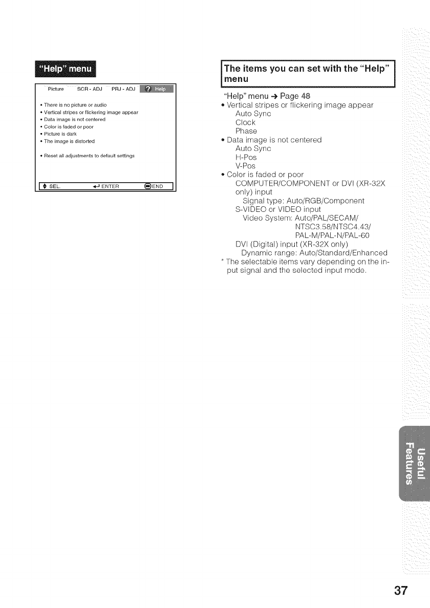
Picture SCR - ADJ PRJ - ADJ
• There is no picture or audio
• Vertical stdpes or flickering image appear
• Data image is not centered
• Color is faded or poor
• Picture is dark
• The image is distorted
• Reset all adjustments to default settings
I _ SEL, _ EN'[ER _END I
IThe you can set "Help"
items with the
menu
"Help" menu 4 Page 48
®Vertical stripes or flickering image appear
Auto Sync
Clock
Phase
®Data image is not centered
Auto Sync
H-Pos
V-Pos
®Color is faded or poor
COMPUTER/COMPONENT or DVt (XR-32X
only) input
Signal type: Auto/RGB/Component
S-VIDEO or VIDEO input
Video System Auto/PAL/SECAM/
NTSC3.58/NTSC4.43/
PAL-M/PAL-N/PAL-60
DVI (Digital) input (XR-32X only)
Dynamic range: Auto/Standard/Enhanced
* The selectable items vary depending on the in-
put signal and the selected input mode.
i i i_ii
_ iiI ii
!i i !ililliiI
37
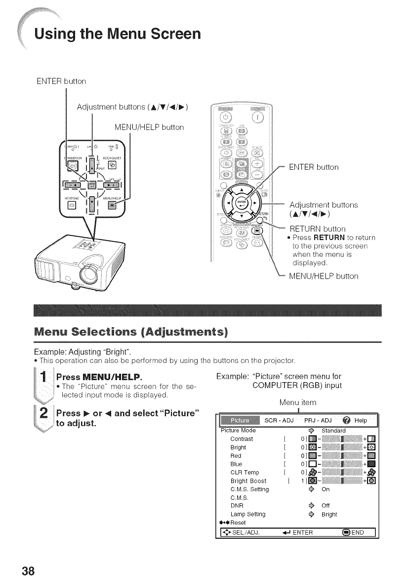
Using the Menu Screen
ENTER button
ENTER button
-- Adjustment buttons
(A/V/</_)
RETURN button
Press RETURN to return
to the previous screen
when the menu is
displayed.
MENU/HELP button
Menu $emectiens {Adjustments}
Example: Adjusting "Bright".
®This operation can also be performed by using the buttons on the projector.
1 oss.s../.sLp.
.The "Picture" menu screen for the se-
lected input mode is displayed.
%;; to adjust.
Example: "Picture" screen menu for
COMPUTER (RGB)input
Menu item
1
SCR - ADJ PRJ :ADJ @ Help
Picture Mode _ Standard
Contrast [ 0]_-_ ,_ _+_
Bright [ 0]_- :!:_ _ + LE"_,I
Red [ 0]_-:: :_ _+_
Blue [ 0][--I- j _:+_
CLmTernp [ 0],._-:_ J:;: +,,_
Bright Boost [ 1 ]_- _ +r_
CM.S. Setting _ On
CM.S.
DNR _ Off
Lamp Setting _ Bright
_,_Reset
I'q:_SEL,/ADJ. _ ENTER (_END I
38
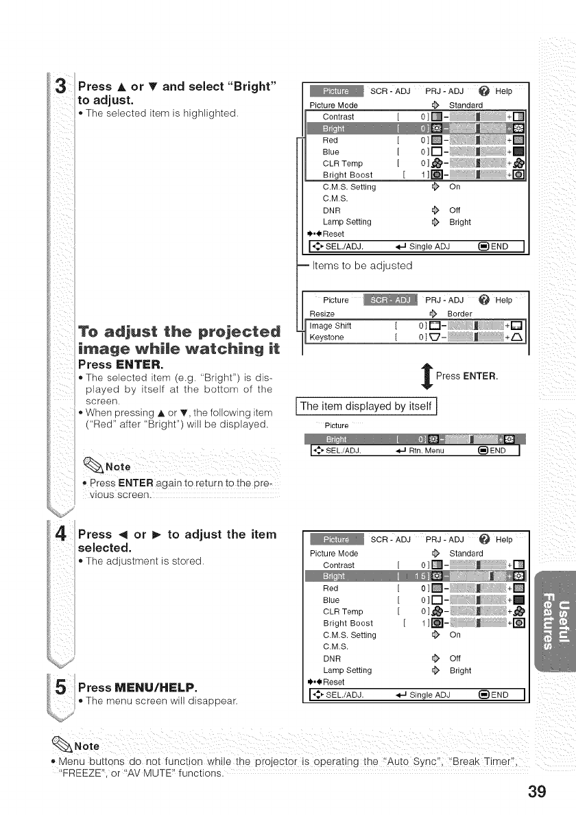
Press Aor T and select "Bright"
to adjust.
•The selected item is highlighted=
_,press ENTER again to retum t0 the pre-
ViOMS screen.
Press < or I_ to adjust the item
selected.
•The adjustment is stored=
5The menu screen will disappear.
SCR - ADJ PRJ - ADJ _ Help
Picture Mode @ Standard
Contrast [ 0 ] []- +D
Red [ 0][]-_ _,/+[]
Blue [ 0 ] [] +ml
CLRTernp [ 0]_- .t , :i +,t_
Bright Boost [ 1 ]_- +r_
CM.S. Setting _ On
CM.S.
DNR ¢ Off
Lamp Setting _ Bright
_,_ Reset
,4_, SEL./ADJ. _J Single ADJ (_ END
Items to be adjusted
Picture _ PRJ- ADJ @ Help
Resize _ Border
Image Shift [ 0]_-_i _i J +_
Keystone [ 0 ] _-S_ _,+/-_
Press ENTER.
[The item displayed by itself]
Picture
I_'SEL./ADJ. .,t-I Rtn. Menu I_}END I
SCR- ADJ PRJ .-ADJ _ Help
Picture Mode @ Standard
Contrast [ 0 ] []- +r_
Red [ O][]-_
Blue [ 0 ] []- _ +[]
CLR Ternp [ 0 ],_-::i +,,,_
Bright Boost [ 1]_- m +1_
CM.S. Setting _ On
CM.S.
DNR _ Off
Lamp Setting _ Bright
_',_ Reset
I_ SEL/ADJ. _ Single ADJ _) END I
iii iI
_,Menu buttons do not functi0n while the projector is ope[ating the _!Auto Sync"i ,Break Tirneri!;
"FREEZE", or _AVMUTE" functions.
39
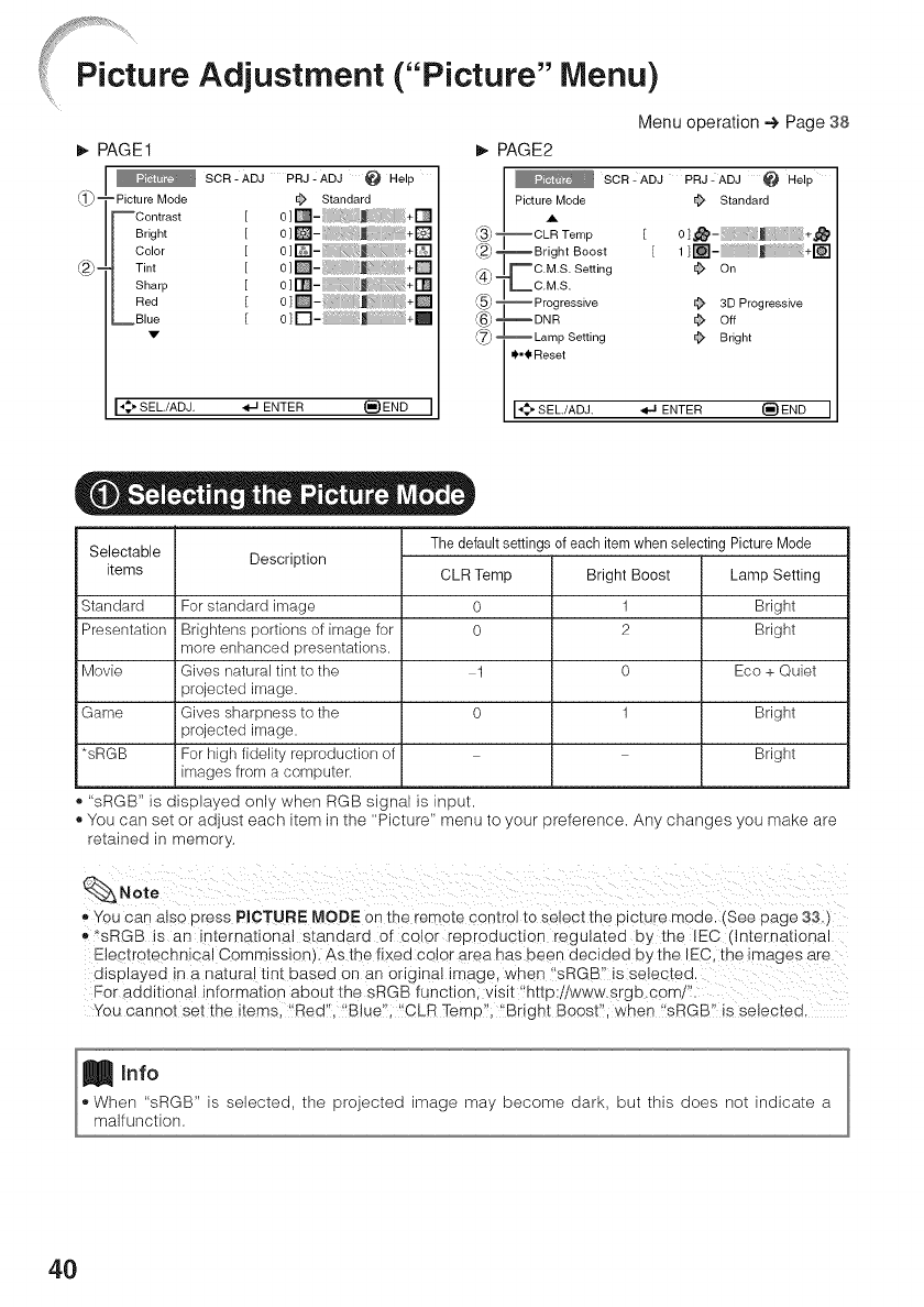
%%,,,....
Picture Adjustment (='Picture" Menu)
Menu operation -+ Page 38
PAGE1
SOR- ADJ PRJ- ADJ @ Help
L1)_ =Picture Mode
--Contrast
Bright
Color
(2j_-Tint
Sharp
Red
_Blue
V
•'_" SEL./ADJ.
Standard
[ o;[] - +[]
[ o][] -+[]
[ o;[]- i:j /+[]
[ o][] - +[]
[ o;[] - +[]
I o][] - +[]
[o]D- J +_
ENTER _)END I
PAGE2
SOR- ADJ PRJ- ADJ @ Help
Picture Mode _ Standard
A
--CLR Temp [ 0]_- ;_::_ _+_
_Bright Boost [ 1 ] _ i _ +_
mC.M.S. Setting _ On
__C.M.S.
--Progressive _ 3D Progressive
_BNR _ Off
_Lamp Setting _ Bright
_._Reset
[_ SEE/ADJ. _ ENTER _)END
Selectable
items
Standard
Presentation
Movie
Game
*sRGB
Description The default settings of each item when selecting Picture Mode
For standard image
Brightens portions of image for
more enhanced presentations.
Gives natural tint to the
projected image.
Gives sharpness to the
projected image.
For high fidelity reproduction of
images from a computer.
CLR Temp
0
0
1
0
Bright Boost
1
2
0
1
Lamp Setting
Bright
Bright
Eco + Quiet
Bright
Bright
"sRGB" is displayed only when RGB signal is input.
• You can set or adjust each item in the "Picture" menu to your preference. Any changes you make are
retained in memory.
,, You can also press PICTURE MODE o n the remote control to select the picture mode. (See page 33.)
,,*sRGB is an international standard of color reproduction regulated by the IEC (International
Electrotechnica! Commission) As the fixed cojer area has been decided by the IEC, the image s are
displayed in a naturaj tint based on an original image, when !IsRGB'! is selected.
For additional informationaboutthesRGBfunctionivisit'http:iiwww.srgb.com/".
You cannot set the items !Redl, !B!ueill !CLR Temp'; '!Bright Boostl, when !sRGB7 is selected,
_Info
, When "sRGB" is selected, the projected image may become dark, but this does not indicate a
malfunction.
4O
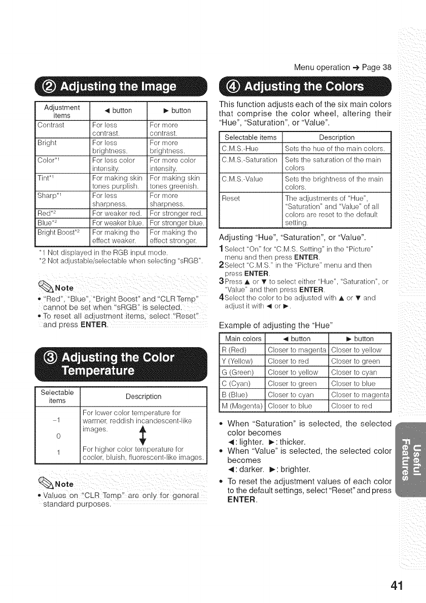
Menu operation 4 Page 38
Adjustment _1 button I)- button
items
Contrast For less For more
contrast, contrast.
Bright For less For more
brightness, brightness.
Color *_ For less color For more color
intensity, intensity.
Tint .1 For making skin For making skin
tones purplish, tones greenish.
Sharp .1 For less For more
sharpness, sharpness.
Red .2 For weaker red. For stronger red.
Blue .2 For weaker blue. For stronger blue.
Bright Boost .2 For making the For making the
effect weaker, effect stronger.
"1 Not displayed in the RGB input mode.
*2 Not adjustable/selectable when selecting "sRGB".
t "Red", "Blue", "Bright Boost" and "CLR Temp"
cannet be set when '_sRGB!' is selected:
_,To reset all adjustment items, select !'Reset"
and press ENTER.
Selectable
items
1
0
1
Description
For lower color temperature for
warmer, reddish incandescentqike
images.
For higher color temperature for
cooler, bluish, fluorescent-like images.
, Values on "CLB Temp'! are only tot general
standard purposes.
This function adjusts each of the six main colors
that comprise the color wheel, altering their
"Hue", "Saturation", or "Value".
Selectable items Description
C.M.S.-Hue Sets the hue of the main colors.
C.M.S.-Saturation Sets the saturation of the main
colors
C.M.S.-Value Sets the brightness of the main
colors.
Reset The adjustments of "Hue",
"Saturation" and "Value" of all
colors are reset to the default
setting.
Adjusting "Hue", "Saturation", or "Value".
1 Select "On" for "C.M.S. Setting" in the "Picture"
menu and then press ENTER.
2Select "C.M.S." in the "Picture" menu and then
press ENTER.
:3 Press A or T to select either "Hue". "Saturation", or
"Value" and then press ENTER.
4.Select the color to be adjusted with A or T and
adjust it with _1 or I)-.
Example of adjusting the "Hue"
Main colors _1 button !_ button
R (Red) Closer to magenta Closer to yellow
Y (Yellow) i Closer to red Closer to green
G (Green) Closer to yellow Closer to cyan
C (Cyan) i Closer to green Closer to blue
B (Blue) Closer to cyan Closer to magenta
M (Magenta) Closer to blue Closer to red
o When "Saturation" is selected, the selected
color becomes
41: lighter. _,: thicker.
,, When "Value" is selected, the selected color
becomes
41: darker. _,: brighter.
,, To reset the adjustment values of each color
to the default settings, select "Reset" and press
ENTER.
ii
i: ii i_
ii___iii i
i!il i _
_i:ii
41
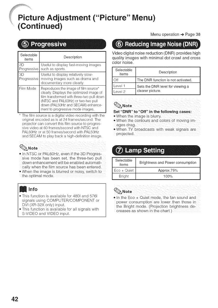
Menu operation 4 Page 38
Selectable
items Description
2D
Progressive
3D
Progressive
Useful to display fast-moving images
such as sports.
Useful to display relatively slow-
moving irnages such as drarna and
documentary more clearly.
Fikn Mode Reproduces the image of film source*
clearly. Displays tile optimized image of
film transformed with threeqwo pull down
(NTSC and PAL60Hz) or two-two pull
down (PALSOHz and SECAM) enhance-
ment to progressive mode images.
" The _'_ source s a dig [al video recording Nim me
)rig na encoded as is at 24 frames _second. The
Drolecror can conver[ this filr_ source to :)rogres-
sive video at 60 frames second with NTSC and
PAL60Hz or at 50 frarne_ ,second wire PAL50Hz
and SECAM to play Dac_ a nigh-definition naoe.
_Note
,, n NTSC or PAL60Hz even if the 3D Progres-
sive mode has been set. the three-two pu
down ennancemenl:wiil be enabled automati-
ca Wwhen the film so drce nas been en[erea
• WPen the Image is Dlurrea or nols_.. SWl]:cn ]:o
!:ne oo[ima mode.
Video digital noise reduction (DNR) provides high
quality images with minimal dot crawl and cross
color noise.
Selectable
items
Off
Level 1
Level 2
Description
[The DNR function is not activated.
Sets the DNR level for viewing a
iclearer picture.
Note
Set "DNR" to "Off" in the following cases:
a When tne mage ts blurr_
When the con[ours and colors of me Ing im-
ages drag
®When TV uroaacas[s Wll:n Weak signals are
projec[eo.
Selectable
items Brightness and Power consumption
Eco + Quiet Approx.75%
Bright 100%
In the Eco + Quiet mode, the tan sound and
pewer consumption are !ower than those in
the Bright mode. (Projection brightnes s de-
creases as shown in the chart.)
42
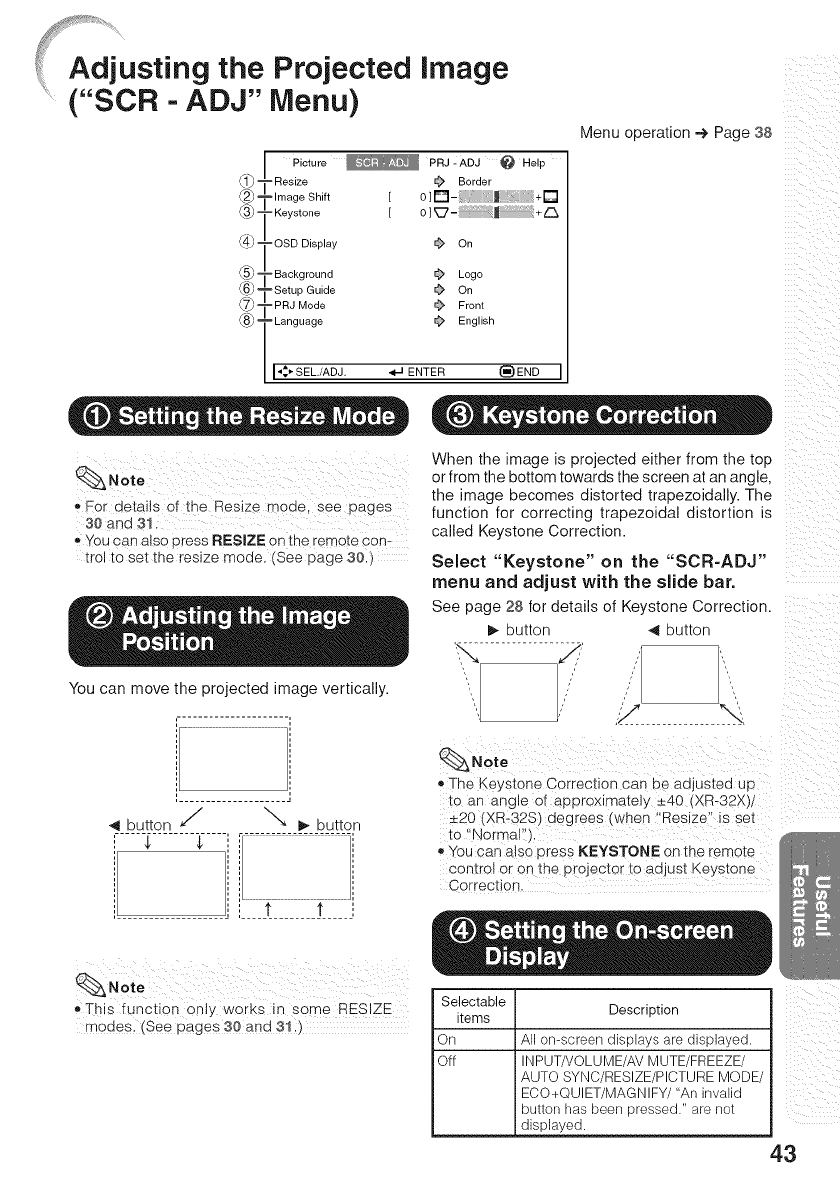
....ji!_!¢_¸¸_'_'¸¸'_....................
®°
@-
@-
@-
@-
Picture _ PRJ - ADJ _ Help
Resize _ Border
-Image Shift [ 0]D-_ _ ;+D
-Keystone [ 0] _7- J_ +r'k.
-OSD Display _ On
- Background _ Logo
-Setup Guide _ On
-PRJ Mode _ Front
-Language _ English
I_SEL./ADJ. ,,_IJENTER _)END I
(_Note
o For details of the Res_ze mode see pages
30 and _1
o You can also oress RESlZE on [ne remote con-
trol to set [ne reslze mode. (See page 30
You can move the projected image vertically.
Menu operation -€ Page 38
x
x
x
x
iiill !i_
When the image is projected either from the top
or from the bottom towards the screen at an angle,
the image becomes distorted trapezoidally. The
function for correcting trapezoidal distortion is
called Keystone Correction.
Selecl "Keystone" on the "SCR-ADJ"
menu and adjust with the slide bar.
See page 28 for details of Keystone Correction.
D, _u_on 4 DU_On
,.Y "4
4 DuEor _" ""- _ DuEon
..........................................
$ $
t t
(_Note
® The Keystone Correction can oe adjusted up
[o an ang e of approximately _+40 (XR-32X_/
=20 tXR-32S_ degrees i when "Reslze s sel
to Normal"
_, You can also oress KEYSTONE on the remote
control or on the projector to adjust Key_ lone
Correction
,, This function 0nty works in s0me RESIZ E
modes_ (See pages 30 and 3!.)
Selectable
items Description
On
Off
All omscreen displays are displayed.
INPUTHOLUME/AV MUTE/FREEZE/
AUTO SYNC/RESIZE/PICTURE MODE/
ECO+QUIET/MAGNIFY/"An invalid
button has been pressed." are not
displayed.
43
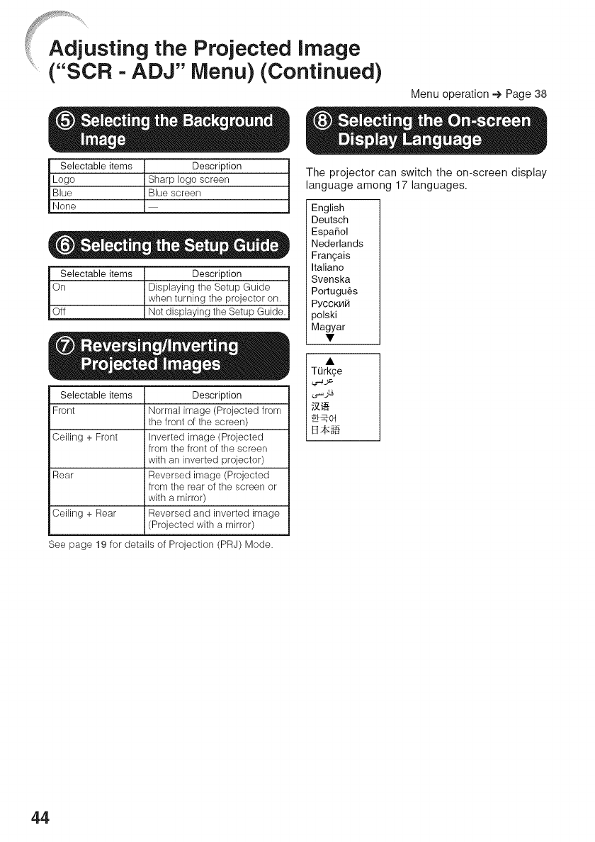
....ji!,!¢_¸¸_'_'¸¸'_....................
Menu) (Continued)
Menu operation -e,Page 38
Selectable items Description
Logo Sharp logo screen
Blue Blue screen
None
Selectable items Description
On Displaying the Setup Guide
when turning the projector on.
Off Not displaying the Setup Guide.
Selectable items Description
Front Normal image (Projected from
the front of the screen)
Ceiling + Front Inverted image (Projected
from the front of the screen
with an inverted projector)
Rear Reversed image (Projected
from the rear of the screen or
with a mirror)
Ceiling + Rear Reversed and inverted image
(Projected with a mirror)
See page 19 for details of Projection (PRJ) Mode.
The projector can switch the on-screen display
language among 17 languages.
English
Deutsch
EspaSol
Nederlands
Fran£ais
Italiano
Svenska
Portugu_s
PYCCKH_
)olski
Magyar
TQrkge
.._ _
_._;_
44
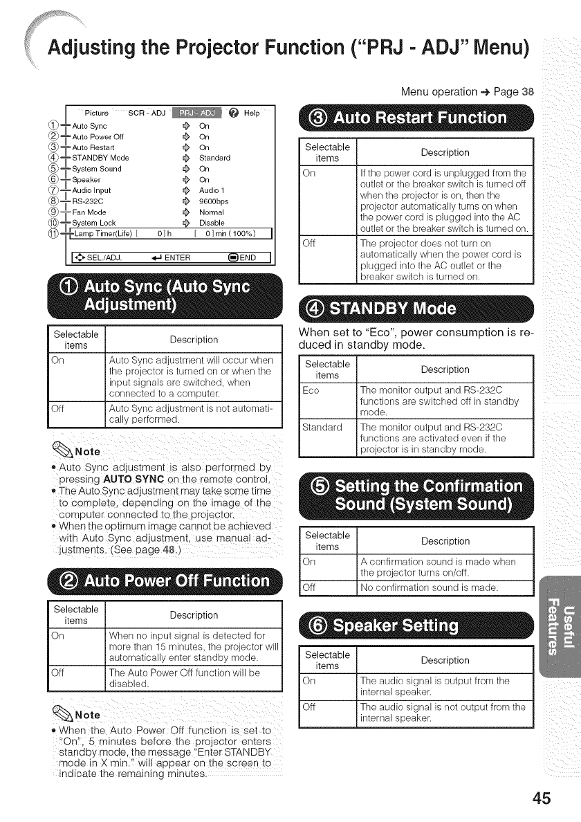
justing the Projector Function ("PRJ - ADJ" Menu)
@°
@°
@°
@°
@°
@°
@°
@°
@°
@°
Picture SOR : ADJ _ _ Help
-Auto Sync _ On
-Auto Power Off _ On
-Auto Restart _ On
-STANDBY Mode _ Standard
-System Sound _ On
-Speaker _ On
=Audio Input _ Audio 1
- RS-232C _ 9600bps
-Fan Mode _ Normal
-System Lock _ Disable
-Lamp Timer(Life) [ 0] h [ 0] rain (100%) I
I,_,,SEL./ADJ. _ ENTER _}END I
Selectable
items Description
On Auto Syne adjustment will occur when
the projector is turned on or when the
input signals are switched, when
connected to a computer,
Off Auto Sync adjustment is not autornati-
cally performed.
_,Auto Sync adjustment iS also performed by
pressing AUTO SYNC on the remote control,
_,The Auto Sync adjustment may take some time
complete, depending on the image of the
computer connected to the projector.
,, When the opt!mum image cannot be aPhieved
with Auto Sync ad ustment, use manual ad_
justments, (See page 48.)
Selectable
items Description
On When no input signal is detected for
more than 15 minutes, the projector will
automatically enter standby mode,
Off The Auto Power Off function will be
disabled,
,*When the Auto Power Off function is set to
t!On:', 5 minutes before the projector enters
standby mode, the message itEnte_STANDBY
mode in X rain!!! will appear on the screen to
indicate the remaining minutes.
}? i¸
Menu operation @ Page 38
Selectable
items Description
On If the power cord is unplugged from the
outlet or the breaker switch is turned off
when the projector is on. then the
projector automatically turns on when
the power cord is plugged into the AC
outlet or the breaker switch is turned on.
Off The projector does not turn on
automatically when the power cord is
plugged into the AC outlet or the
breaker switch is turned on.
When set to "Eco", power consumption is re ....
duced in standby mode.
Selectable
items Description
Eco The monitor output and RS-232C
functions are switched off in standby
rnode.
Standard The monitor output and RS-232C
functions are activated even if the
projector is in standby mode.
Selectable Description
I items
On A confirmation sound is made when
I the projector turns on/off.
I
Off [No confirmation sound is made.
Selectable I ....
I items I uescnp[,on
I On I The audio signal is output from the
I I internal speaker.
Off I The audio signal is not output from the
_internal speaker.
45
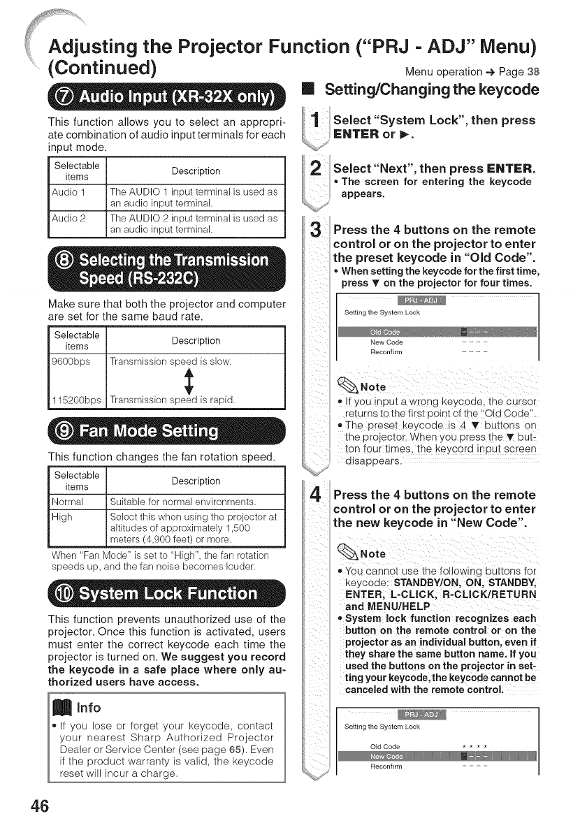
Adjusting the Projector Function ("PRJ - ADJ" Menu)
.......(Continued) Menu operation -€ Page 38
Setting/Changing the keycode
This function allows you to select an appropri-
ate combination of audio input terminals for each
input mode.
Selectable
items Description
Audio 1 The AUDIO 1 input terminal is used as
an audio input terminal.
Audio 2 The AUDIO 2 input terminal is used as
an audio input terminal.
Make sure that both the projector and computer
are set for the same baud rate.
Selectable
items Description
9600bps Transmission speed is slew.
115200bps Transmission speed is rapid.
This function changes the fan rotation speed.
Selectable
items Description
Normal Suitable for normal environments.
High Select this when using the projector at
altitudes of approximately 1,500
meters (4,900 feet) or more.
When "Fan Mode" is set to "High", the fan rotation
speeds up, and the fan noise becomes louder.
This function prevents unauthorized use of the
projector. Once this function is activated, users
must enter the correct keycode each time the
projector is turned on. We suggest you record
the keycode in asafe place where only au-
thorized users have access.
Select "System Lock", then press
ENTER or _.
Select "Next", then press ENTER.
, The screen for entering the keycode
appears.
Press the 4 buttons on the remote
control or on the projector to enter
the preset keycode in "Old Code".
=When setting the keycode for the first time,
press T on the projector for four times.
Setting the Sysfem Lock
New Code
Reconfirm
If you input a wrong keycode, the Cursor
returns to the firSt point of the Old CodelL
,,The preset keycode is 4 T buttons on
the projector. When you press the 1!' but_
ton four times, the keycord input screen
disappears.
Press the 4 buttons on the remote
control or on the projector to enter
the new keycode in "New Code".
(_Note
,, You cannot use the foltowmg ounons for
Keycode: STANDBY/ON, ON, STANDBY,
ENTER, L-CLICK, R-CLICK/RETURN
and MENU/HELP
System lock function recognizes each
button on the remote control or on the
projector as an individual button, even if
they share the same button name. If you
used the buttons on the projector in set-
ting your keycode, the keycode cannot be
canceled with the remote control.
Setting the System Lock
Old Code
Reconfirm ........
46

Enter the same keycode in "Re-
To Cancel the keycode that you have already
set
,, Press V on the projector for four times in steps
4 and 5 above.
When the System Lock iS set
,, W'hen System Lock !s set, the keycode input
screen appears after the power is turned on
When it appears enter the right keycode to
Start Pr0jection.
Input screen for keycode
I I
You can confirm the cumulative lamp usage time
and the remaining lamp life (percentage).
Lamp usage condition
"Life"
Operated exclusively
with Lamp Setting set to
"Eco +Quiet"
Operated exclusively
with Lamp Setting set to
"Bright"
Remaining lamp life
100% 5%
Approx. Approx.
4,000 200 hours
hours
Approx. Approx.
2,000 100 hours
hours
_, tt is recommended that the lamp be changed
when the remaining lamP life becomes 5%.
_,The lamp life may vary depending on the us-
age condition.
Locking the Operation
Buttons on the Projector
Use this function to lock the operation buttons
on the projector.
mLocking the Operation Buttons
Hold down ENTER on the projector for about 5
seconds while the projector is being turned on.
On-screen display
®The keylock function does not affec[ the opera-
tion with the remote control buttons.
®You cannot use the keylock function while the
projector is warming up.
[]Taking the Keylock off
Hold down ENTER on the projector for about 5
seconds.
On-screen display
i i_i i
®When the projecIor is in standby mode, you can
release [he keylock by holding down ENTER
and STANDBY/ON on the prejecIor simulta-
neously for abou[ 5 seconds.
Info
,, Keylock cannot be set while the projector is:
displaying the "Setup Guide" or "Menu"
screens, in standby mode, warming up, chang-
ing inpu[ signals, operating "Auto Sync" func-
tion, in "FREEZE" mode or on the "SysIem
Lock" screen during warming up.
ii
/i _ii
47
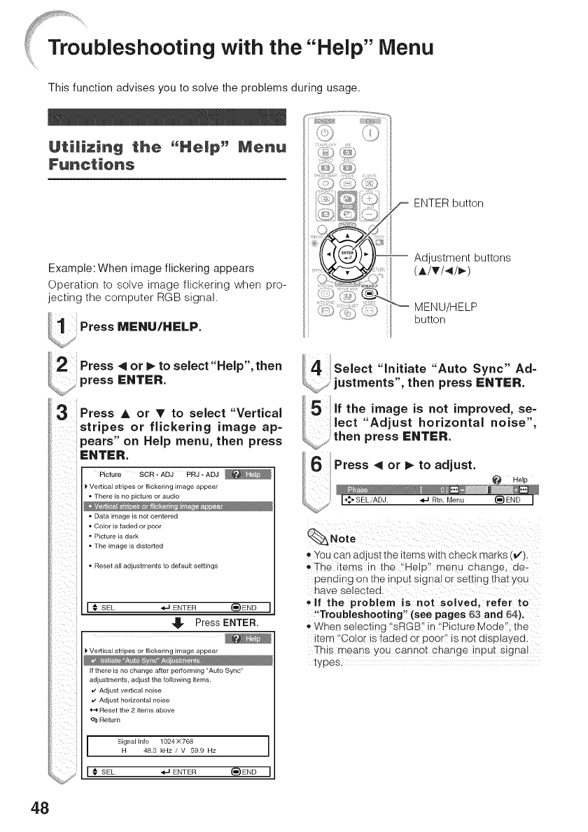
Troubleshooting with the "Help" Menu
This function advises you to solve the problems during usage.
Utilizing the "Help" Menu
Example: When image flickering appears
Operation to solve image flickering when pro-
jecting the computer RGB signal.
Press MENU/HELP.
ENTER button
Adjustment buttons
(A/T/</_)
MENU/HELP
button
Press < or I_ to select "Help", then
press ENTER.
3Press _, or T to select "Vertical
stripes or flickering image ap-
pears" on Help menu, then press
ENTER.
Picture SCR -ADJ PRJ -ADJ
Vertical stripes or flickering image appear
There is no picture or audio
Data image is not centered
Color is faded or poor
Picture is dark
The image is distorted
Reset all adjustments to default settings
SEL _ ENTER _END
_- Press ENTER.
_"Vertical stripes or flickering image appear
if there is no change after performing "Auto Sync'
adjustments, adjust the following items,
v' Adjust vertical noise
*/ Adjust horizontal noise
*,4, Reset the 2 items above
¢b Return
Signal Info 1024 X 768 I
H 48.3 kHz /V 59.9 Hz I
Select "initiate "Auto Sync" Ad=
justments", then press ENTER.
5,fthe magenot mproved,se-
_-- lect "Adjust horizontal noise",
_ then press ENTER.
Press < or I_ to adjust.
Help
I*$_SEL.iADJ. *J Rtn. Menu (_)END I
Note
® You can aQjLiSitlqe [ems wtIn CnGC_ marks (V'),
o The Items In [n£ Melo menu cnange, oe-
pending on _ne inpu[ signs or selling mat you
na e selectee
elf the problem is not solved, refer to
"Troubleshooting" (see pages 53 and 54).
_, When selecting 'sRGB' in "Picture Mode' _ne
Item 'Color is faded or Door" is not dlsptayeo.
This means _ou cannel change Input signal
types.
48
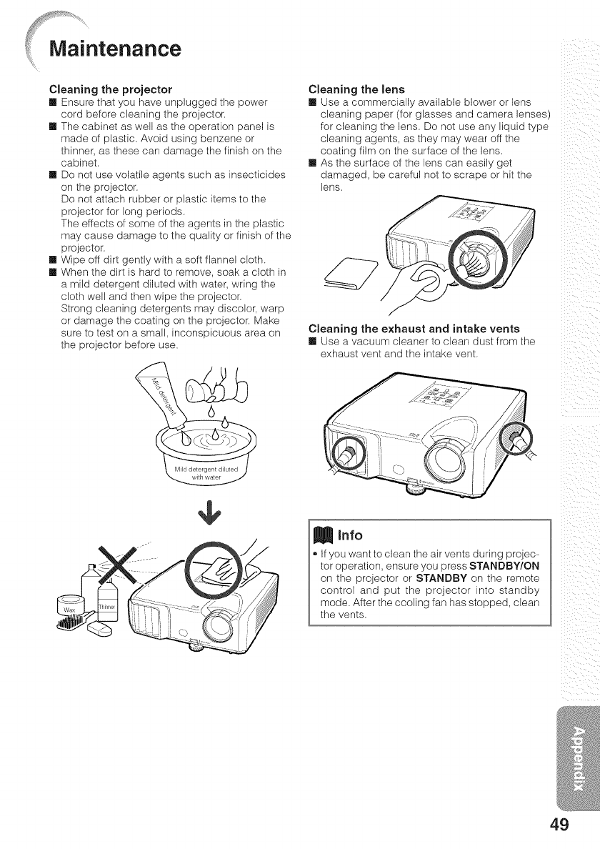
Cleaning the projector
[] Ensure that you have unplugged the power
cord before cleaning the projector,
[] The cabinet as well as the operation panel is
made of plastic, Avoid using benzene or
thinner, as these can damage the finish on the
cabinet.
[] Do not use volatile agents such as insecticides
on the projector.
Do not attach rubber or plastic items to the
projector for long periods.
The effects of some of the agents in the plastic
may cause damage to the quality or finish of the
projector.
[] Wipe off dirt gently with a soft flannel cloth.
[] When the dirt is hard to remove, soak a cloth in
a mild detergent diluted with water, wring the
cloth well and then wipe the projector.
Strong cleaning detergents may discolor, warp
or damage the coating on the projector, Make
sure to test on a small, inconspicuous area on
the projector before use.
÷
Cleaning the lens
[] Use a commercially available blower or lens
cleaning paper (for glasses and camera lenses)
for cleaning the lens= Do not use any liquid type
cleaning agents, as they may wear off the
coating film on the surface of the lens=
[] As the surface of the lens can easily get
damaged, be careful not to scrape or hit the
lens=
Cleaning the exhaust and intake vents
[] Use a vacuum cleaner to clean dust from the
exhaust vent and the intake vent.
Info
.If you want to clean the air vents during projec-
tor operation, ensure you press STANDBY/ON
on the projector or STANDBY on the remote
control and put the projector into standby
mode. After the cooling fan has stopped, clean
the vents=
_iiiI _! ii_
i i !ii_i
49
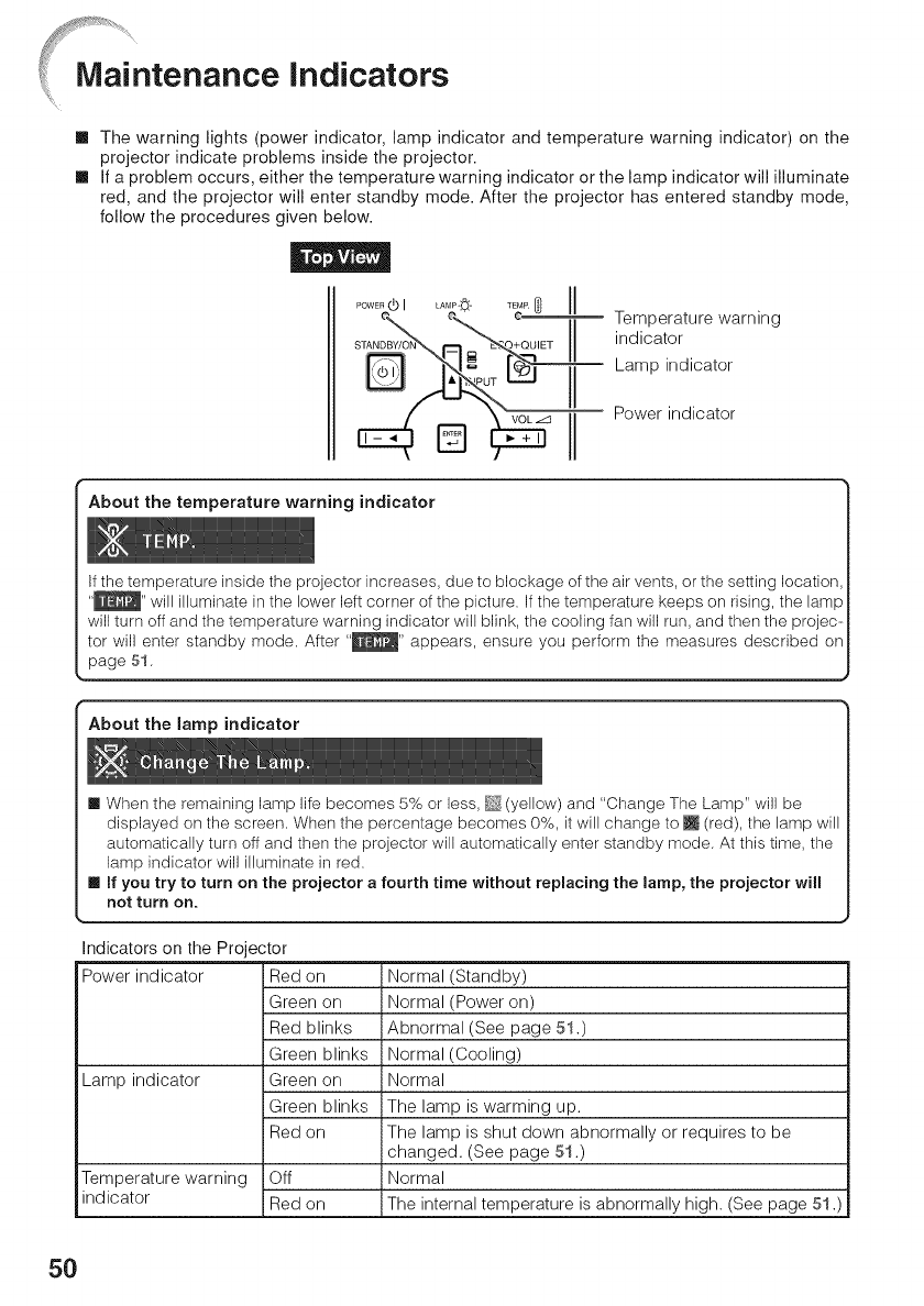
[] The warning lights (power indicator, lamp indicator and temperature warning indicator) on the
projector indicate problems inside the projector.
[] If a problem occurs, either the temperature warning indicator or the lamp indicator will illuminate
red, and the projector will enter standby mode. After the projector has entered standby mode,
follow the procedures given below.
Lamp indicator
l Power indicator
About the temperature warning indicator
if the temperature inside the projector increases, due to blockage of the air vents, or the setting location,
"_" will illuminate in the lower left corner of the picture= If the temperature keeps on rising, the lamp
will turn off and the temperature warning indicator will blink, the cooling fan will run, and then the projec-
tor will enter standby mode= After "_P_" appears, ensure you perform the measures described on
page 51.
About the lamp indicator
[] When the remaining lamp life becomes 5% or less, _ (yellow) and "Change The Lamp" will be
displayed on the screen= When the percentage becomes 0%, it will change to _ (red), the lamp will
automatically turn off and then the projector will automatically enter standby mode. At this time, the
lamp indicator will illuminate in red=
[] If you try to turn on the projector a fourth time without replacing the lamp, the projector will
not turn on.
Indicators on the Projector
Power indicator Red on
Green on
Red blinks
Green blinks
Lamp indicator Green on
Green blinks
Red on
Temperature warning Off
indicator Red on
Normal (Standby)
Normal (Power on)
Abnormal (See page 51.)
Normal (Cooling)
Normal
The lamp is warming up.
The lamp is shut down abnormally or requires to be
changed. (See page 51 .)
Normal
The internal temperature is abnormally high. (See page 51 .)
5O
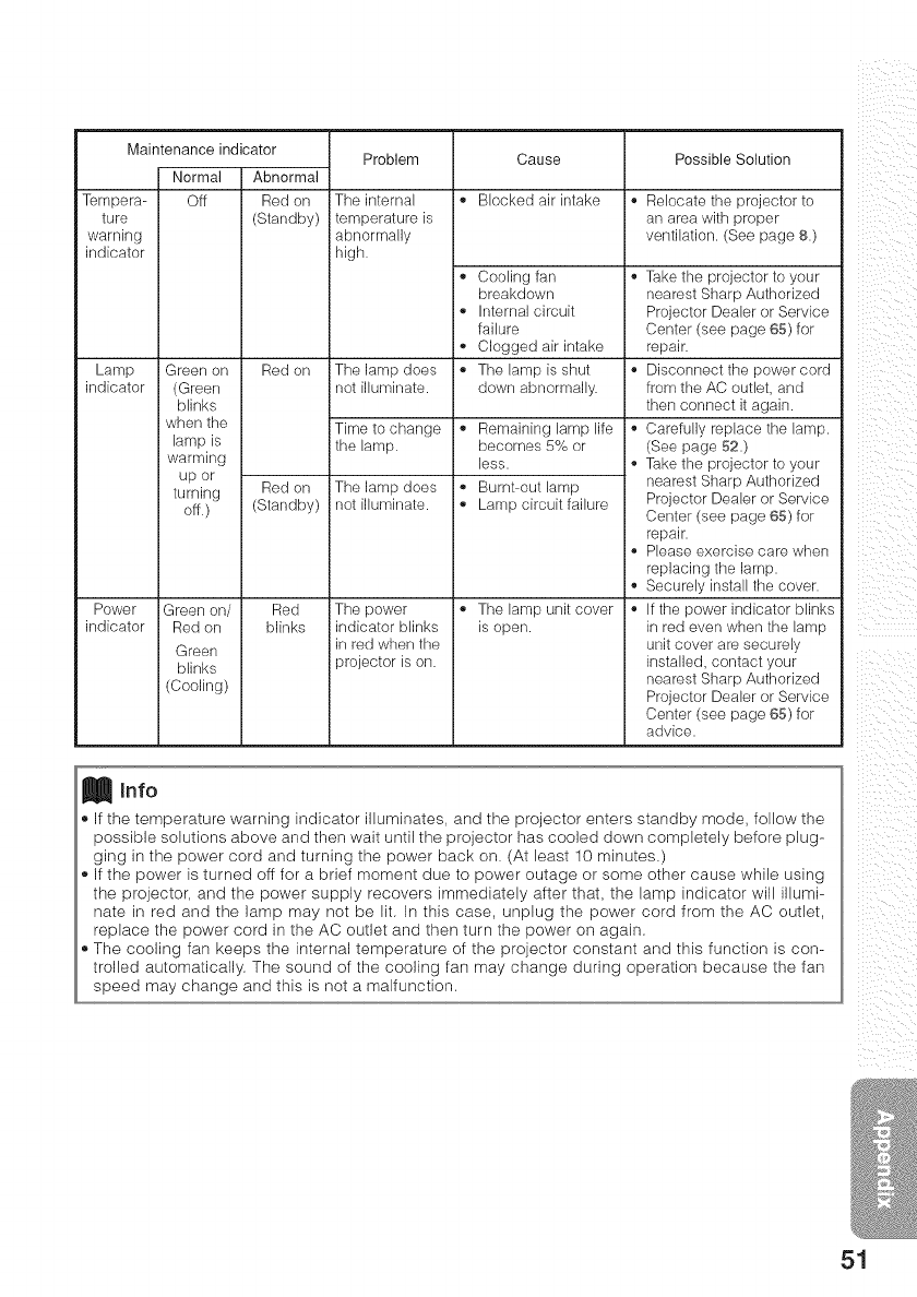
Tempera-
ture
warning
indicator
Lamp
indicator
Power
indicator
Maintenance indicator
Normal Abnormal
Off Red on
(Standby)
Green on Red on
(Green
blinks
when the
lamp is
warming
up or
turning Red on
off.) (Standby)
Green on/ Red
Red on blinks
Green
blinks
(Cooling)
Problem
The internal
temperature is
abnormally
high.
The lamp does
not illuminate.
Time to change
the lamp.
The lamp does
not illuminate.
The power
indicator blinks
in red when the
projector is on.
Cause
i°Blocked air intake
i ° Cooling fan °
breakdown
_° Internal circuit
failure
i ° Clogged air intake
i ° The lamp is shut °
down abnormally.
i° Remaining lamp life °
becomes 5% or
less. •
i ° Burnt-out lamp
i ° Lamp circuit failure
e
e
i ° The lamp unit cover °
is open.
Possible Solution
° Relocate the projector to
an area with proper
ventilation. (See page 8.)
Take the projector to your
nearest Sharp Authorized
Projector Dealer or Service
Center (see page 65) for
repair.
Disconnect the power cord
from the AC outbt, and
then connect it again.
Carefully replace the lamp.
(See page 52.)
Take the projector to your
nearest Sharp Authorized
Projector Dealer or Service
Center (see page 65) for
repair.
Please exercise care when
replacing the lamp.
Securely install the cover.
If the power indicator blinks
in red even when the lamp
unit cover are securely
installed, contact your
nearest Sharp Authorized
Projector Dealer or Service
Center (see page 65) for
advice.
Info
If the temperature warning indicator illuminates, and the projector enters standby mode, follow the
possible solutions above and then wait until the projector has cooled down completely before plug-
ging in the power cord and turning the power back on, (At least 10 minutes,)
If the power is turned off for a brief moment due to power outage or some other cause while using
the projector, and the power supply recovers immediately after that, the lamp indicator will illumi-
nate in red and the lamp may not be lit. In this case, unplug the power cord from the AC outlet,
replace the power cord in the AC outlet and then turn the power on again,
The cooling fan keeps the internal temperature of the projector constant and this function is con-
trolled automatically. The sound of the cooling fan may change during operation because the fan
speed may change and this is not a malfunction.
51
Lamp
[] It is recommended that the lamp (sold separately) be replaced when the remaining lamp life becomes
5% or less, or when you notice a significant deterioration in the picture and color quality. The lamp life
(percentage) can be checked with the on-screen display. (See page 47.)
[] Purchase a replacement lamp of type AN-F212LP from your place of purchase, nearest Sharp
Authorized Projector Dealer or Service Center.
IMPORTANT NOTE TO U.S. CUSTOMERS:
The lamp included with this projector is backed by a 90-day parts and labor limited
warranty. All service of this projector under warranty, including lamp replacement,
must be obtained through a Sharp Authorized Projector Dealer or Service Center.
For the name of the nearest Sharp Authorized Projector Dealer or Service Center,
please call toll-free: 1-888-GO-SHARP (1-888-467-4277).
Hg LAMP CONTAINS MERCURY For State Lamp Disposal
Information
www.lamprecycle.org or 1-800-BE-SHARP [U.S.A. ONLYJ
Cautien Cenceming the Lamp
[] This projector utilizes a pressurized mercury lamp, A loud sound may indicate lamp failure, Lamp
failure can be attributed to numerous sources such as: excessive shock, improper cooling, surface
scratches or deterioration of the lamp due to a lapse of usage time.
The period of time up to failure largely varies depending on the individual lamp and/or the condkion
and the frequency of use. It is important to note that failure can often result in the bulb cracking.
[] When the lamp replacement indicator and on-screen display icon are illuminated, it is recommended
that the lamp be replaced with a new one immediately, even if the lamp appears to be operating
normally.
[] Should the lamp break, there is also a possibility that glass particles may spread inside of the
projector. In such a case, it is recommended you contact your nearest Sharp Authorized Projector
Dealer or Service Center to assure safe operation,
[] Should the lamp break, the glass particles may spread inside the lamp cage or gas contained in the
lamp may be vented into the room from the exhaust vent. Because the gas in this lamp includes
mercury, ventilate the room well if the lamp breaks and avoid all exposure to the released gas. in case
of exposure to the gas, consult a doctor as soon as possible.
Rep|acing the Lamp
:_ Caution
•Do not remove the lamp unit from the projector dght after use. The lamp will be very hot and may
cause burns or injury.
•Wait at least one hour after the power cord is disconnected to allow the surface of the lamp unit to fully
cool before removing the lamp unit,
[] Carefully change the lamp by following the instructions described in this section. *if you wish,
you may have the lamp replaced at your nearest Sharp Authorized Projector Dealer or Service
Center.
* If the new lamp does not light after replacement, take your projector to the nearest Sharp Authorized
Projector Dealer or Service Center for repair.
52
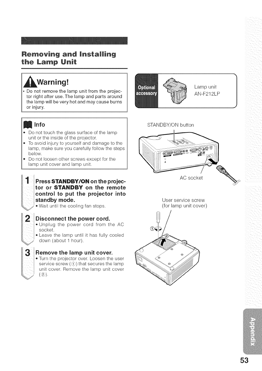
Re_eving and Installing
the La_p Unit
Warning!
Do not remove the lamp unit from the projec-
tor right after use. The lamp and parts around
the lamp will be very hot and may cause burns
or injury.
Info
Do not touch the glass surface of the lamp
unit or the inside of the projector.
To avoid injury to yourself and damage to the
lamp, make sure you carefully follow the steps
below.
Do not loosen other screws except for the
lamp unit cover and lamp unit.
Press STANDBY/ON on the projec-
1
tot or STANDBY on the remote
control to put the projector into
st.ndbymode.
_%,,oy,, ', Wait until the cooling fan stops.
p g p C
/ socket.
Leavethelampuntilit hasfullycooled
uown _about 1 hour)
:3 .,omovo,,o,om °o, ovo..
Turn the projector over. Loosen the user
service screw (_ii i) that secures the lamp
unit cover. Remove the lamp unit cover
Lamp unit
AN-F212LP iii!i i i_ii
!i_ iii i
iii !!i_
STANDBY/ON button
AC socket _-_,_
User service screw
(for lamp unit cover)
ii_ ii
_iiii i
53
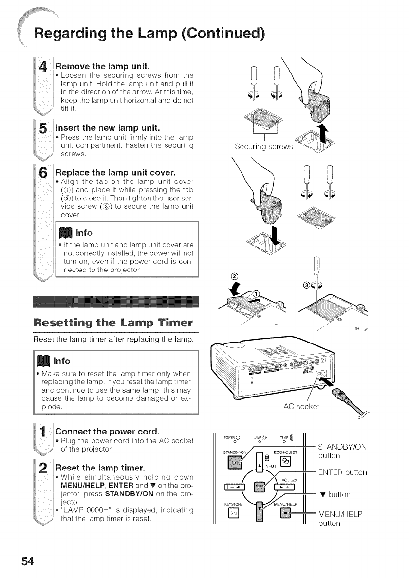
Lamp (Continued)
4 thelampunit.
Femove
Loosen the securing screws from the
lamp unit, Hold the lamp unit and pull it
in the direction of the arrow. At this time,
keep the lamp unit horizontal and do not
L_%_,i, tilt k.
5 the new lamp unit.
Insert
Press the lamp unit firmly into the lamp
t, unit compartment. Fasten the securing
_;%,S"* screws.
Replace the lamp unit cover.
• Align the tab on the lamp unit cover
(_) and place it while pressing the tab
(.2) to close it. Then tighten the user ser-
vice screw (,3",)to secure the lamp unit
cover,
Info
If the lamp unit and lamp unit cover are
not correctly installed, the power will not
turn on, even if the power cord is con-
nected to the projector,
%
®
Resetting the Lamp Timer
Reset the lamp timer after replacing the lamp.
J
@ ../
tiil! Connectthepowercord.
Plug the power cord into the AC socket
_,,_,,,,>,, of the projector.
Reset the lamp timer.
• While simultaneously holding down
MENU/HELP, ENTER and T on the pro-
jector, press STANDBY/ON on the pro-
jector.
• "LAMP 0000H" is displayed, indicating
that the lamp timer is reset.
PowE_(bI
j_ ECO+QUIET
STANDBY/ON
button
ENTER button
T button
MENU/HELP
button
54

Connecting Pin Assignments
COMPUTER/COMPONENT input and COMPUTER/COMPONENT output Terminals : mini D-
sub 15 pin female connector
COMPUTER Input/Output COMPONENT Input/Output
Pin No. Signal Pin No. Signal
1. Video k_put (red) 1. PR (OR)
1__1 ..... 15 2. Video input (green/sync on green) 2. Y
4. Not connected 4. Not connected
O___Oj 5. Not ........ ted 5. Not ...... ted
6. Earth (red) 6. Earth (PR)
7. Earth (green/sync on green) 7. Earth (Y)
8. Earth (Mue) 8. Earth (PB)
9. Not connected 9. Not connected
10. GND 10. Not connected
11. Not connected 11. Not connected
6 ....... 10 12. BEdirectional data 12. Not connected
13. Horizontal sync signaE: TTL Eevel 13. Not connected
14. Vertical sync signaE: TTL level 14. Not connected
15. Data clock 15. Not connected
DVI-D Terminal : 24 pin connector (XR-32X only)
24 ""• 17 Pin No. Signal Pin No. Signal
_!_.1 1. T.M.D.S data2 16. Hot p,ug detection
2. T.M.D.S data 2+ 17. T.M.D.Sdata0
3. T.M.D.S data 2 sMeld 18. T.M.D.S data0+
4. Not connected 19. T.M.D.S data0 sMeld
5. Not connected 20. Not connected
6. DDC clock 21. Not connected
7. DDC data 22. T.M.D.S clock shield
8. Not connected 23. T.M.D.S clock+
9. T.M.D.S data I 24. T.M.D.S clock
10. T.M.D.S data 1+
16• " • 9 11. T.M.D.S data 1 shield
12. Not connected
13. Not connected
14. +SV power
15. Ground
i
55
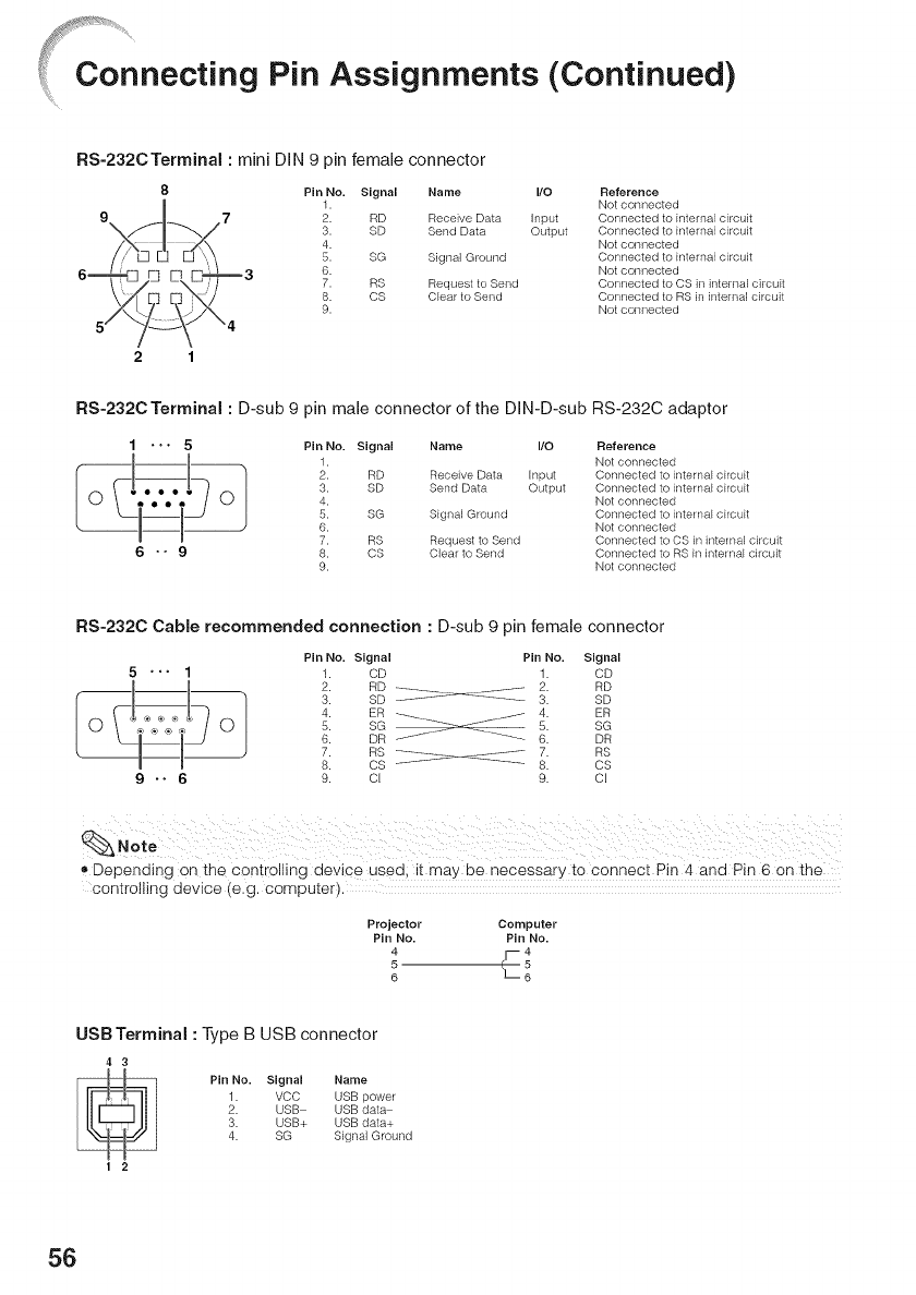
Connecting Pin Assignments (Continued)
RS-232CTerminal : mini DIN 9 pin female connector
8Pin No. Signal Name I/O Reference
1. Not connected
2. RD Receive Data Input Connected to Enternal circuit
3. SD Send Data Output Connected to EnternaEcircuit
4. Not connected
5. SG Signal Ground Connected to EnternaEcircuit
6. Not connected
7. RS Request to Send Connected to CS in internal circuit
8. CS Clear to Send Connected to RS in internal circuit
9. Not connected
2 1
RS-232C Terminal : D-sub 9 pin male connector of the DIN-D-sub RS-232C adaptor
1*"• 5 Pin No. Signal Name I/O Reference
1. Not connected
2. RD Receive Data Input Connected to internal circuit
3. SD Send Data Output Connected to internaE circuit
4. Not connected
5. SG SEgnal Ground Connected to internal circuit
6. Not connected
7. RS Request to Send Connected to CS in internal circuit
6 " "9S. CS Clear to Send Connected to RS in internal circuit
9. Not connected
RS-232C Cable recommended connection : D-sub 9 pin female connector
Pin No. Signal Pin No. Signal
5 ' '' 1 t. CD 1. CD
4. ER ER
5 SG---_--JJ
6. DR J'"J/ .... .____._ 6.5" SGDR
7. RS ........... _ .......... 7. RS
8. CS .................. 8. CS
9 .. 6 9. cl 9. cl
Depending on the controlling device used; it may be necessary to connect Pin 4 and Pin 6 on the
controlling device (e.g. computer).
Projector Computer
Pin No. Pin No.
4_4
5 5
6 6
USB Terminal : Type B USB connector
43
_E_ Pin No. Signal Name
,_ 1. VCC USB power
2. USB USB data
3. USB+ USB data+
4. SG Signal Ground
1 2
56
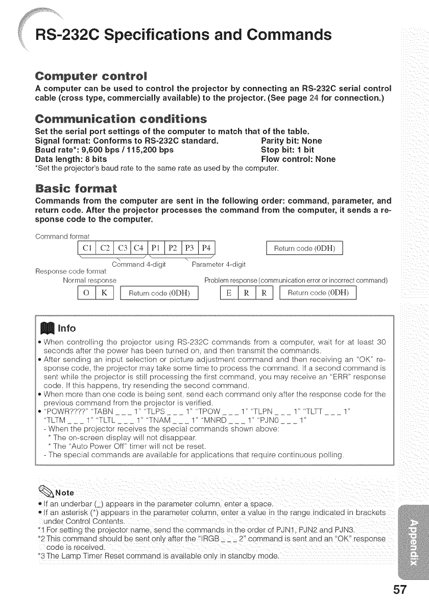
%¸%¸¸¸¸.....
RS-232C Specifications and Commands
Computer centro!
A computer can be used to control the projector by connecting an RS-232C serial control
came (cross type, commercially available) to the projector. (See page 24 for connection.)
Communication conditions
Set the serial port settings of the computer to match that of the table.
Signal format: Conforms to RS-232C standard. Parity bit: None
Baud rate*: 9,600 bps /115,200 bps Stop bit: 1 bit
Data length: 8 bits Flow control: None
*Set the projector's baud rate to the same rate as used by the computer.
Basic format
Commands from the computer are sent in the following order: command, parameter, and
return code. After the projector processes the command from the computer, it sends are-
sponse code to the computer.
i i i_ii
Command format
Ic, Ic2!cslc4 lp, lp2lpslp4J [ Return code (0DH)]
"., \
Command 4-digit Parameter 4-digit
Response code format
NormN response Problem response (communication error or incorrect command)
_ I Returneode(0DH)I I E ! R ! R I[ Returneode(0DH)I
Info
When controlling the projector using RS-232C commands from a computer, wait for at least 30
seconds after the power has been turned on, and then transmit the commands.
After sending an input selection or picture adjustment command and then receiving an "OK" re-
sponse code, the projector may take some time to process the command. If a second command is
sent while the projector is still processing the first command, you may receive an "ERR" response
code. If this happens, try resending the second command.
When more than one code is being sent, send each command only after the response code for the
previous command from the projector is verified.
"POWR????" "TABN ___ 1" "TLPS ___ I" "TPOW ___ 1" "TLPN ___ I" "TLTT ___ 1"
"TLTM ___ 1" "TLTL ___ 1" "TNAM ___ 1" "MNRD ___ 1" "PJN0 ___ 1"
- When the projector receives the special commands shown above
* The on-screen display will not disappear.
* The "Auto Power Off" timer will not be reset.
- The special commands are available for applications that require continuous polling.
Note
_' If an underbar (_) apoears in me Darame[er COlumn. enter a space.
o If an asterisk (*) aeDears n me Darame[er columq, enter a value in [no range Indicated In bracKe[s
under Control Conten[s.
"1 For semng the projector name send the commands in the order of PJNq. PJN2 and PJN3.
2 This co _qmand snouid De sent only after the "IRGB __ 2" commar u s se l[ aria an "OK" response
coae s receweo.
*3 The Ls mp Timer Reset command is available on y in standby moae
57
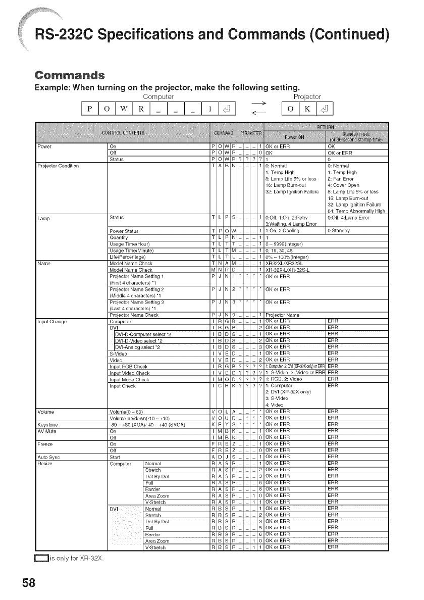
J _Tj'_: _tt_,,_,
RS-232C Specifications and Commands (Continued)
C@mma_ds
Example: When turning on the projector, make the following setting.
Computer Projector
I_ !o !w!_ !- !- !- !, !<_I -_
Projector Condition
Lamp
Input Change
Keystone
Auto Sync
r---_ is only for XR-32X.
Quantity
Usage Time(Hour)
Life(Percentage)
Projector Name Setting 1
(First 4 characters) _1
Projector Name Setting 2
Projector Name Setting 3
(Last 4 characters) _1
Projector Name Check
DVI-D-Computer select *2
DVI-Analog select *2
Input RGB Check
Input Check
(XGA)/-40 =+40 (SVGA)
Normal
Stretch
Dot By Dot
Full
Border
Area Zoom
V=Stretch
Normal
Stretch
Dot By Dot
Full
Border
V-Stretch
1: Temp High
8: Lamp Life 5% or less
Lamp Bum-out
Lamp Ignition Failure
O:Off, l:On, 2:Retry
l:On,2:Cooling
O=9999(Integer)
0,15,30,45
OK
OK or ERR
1 : Temp High
4: Cover Open
8: Lamp Life 5% or less
16: Lamp Bum-out
32: Lamp Ignition Failure
O:Off, 4:Lamp Error
O:Standby
Projector Name
ERR
ERR
ERR
ERR
ERR
ERR
ERR
1:C0mputel,2:DVl(XR-32X0dy)0rERR ERR
ERR
1: BGB, 2: Video ERR
1: Computer ERR
2: DVl (XB-32X only)
ERR
ERR
ERR
ERR
ERR
ERR
ERR
ERR
ERR
ERR
ERR
ERR
ERR
ERR
ERR
ERR
ERR
ERR
ERR
58
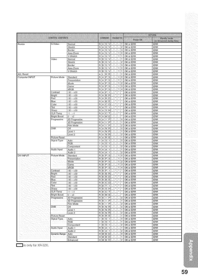
S-Video Normal
Stretch
Border
Area Zoom
V-Stretch
Normal
Stretch
Border
Area Zoom
Computer INPUT Picture Mode Standard
Presentation
Movie
_Game
sRGB
Contrast -30 +30
Red -30 +30
Blue -30 +30
Color -30 +30
Tint -30 +30
Sharp -30 +30
CLR Temp -1 +1
_Bright Boost 0 +2
Progressive 2D Progressive
3D Progressive
Film Mode
DNR Off
Level 1
Picture Reset
Sigilal Type I Auto
RGB
Compontent
Audio Input I Audio 1
Audio 2
DVl INPUT Picture Mode I Standard
i
Presentation
Movie
Game
sRGB
i
Contrast 1-30 - +30
Briqht I -30 - +30
R_d i-ao-+ao
.... ,_3o_ 3o
T#_t 1-30 -- +30Sharp
CLRProgressiyeTemp -12D-Progressive+1
Bdgh,Boo_t0-+2
3B Progressive
ONR ioi_Mode_,m
Level 1
Level 2
P_otureBeset'
Signal TYPe AutoCompontent
Audiohput Aud_o2AUd_°t
_Standard
is only for XR-32X.
59
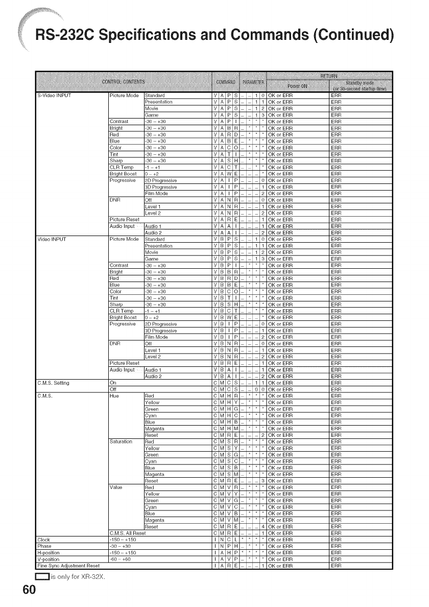
RS-232C Specifications and Commands (Continued)
C.M.S. Setting
H-position
V-position
Fine Sync Adjustment Reset
r=""l is only for XR-32X.
60
Picture Mode Standard
Presentation
Movie
Game
Contrast -30 +30
Bright -30 +30
Red -30 +30
Blue -30 +30
Color -30 +30
Tint -30 +30
Sharp -30 +30
CLR Temp -1 +1
Bright Boost 0 +2
Progressive 2D Progressive
3D Progressive
Film Mode
DNR Off
Level 1
Picture Reset
Audio Input Audio 1
Audio 2
Picture Mode Standard
Presentation
Movie
Game
Contrast -30 +30
Bright -30 +30
Red -30 +30
Blue -30 +30
Color -30 +30
Tint -30 +30
Shalp -30 +30
CLR Temp -1 +1
Bright Boost 0 +2
Progressive 2D Progressive
Film Mode
DNR _ode
DNR Off
Level 1
Picture Reset
_Audio Input Audio 1
On
Off
Hue IRed
Yellow
Green
Cyan
Blue
Magenta
Reset
Saturation IRed
Yellow
Green
Cyan
Blue
Magenta
Reset
Value JRed
Yellow
Green
Cyan
Blue
Magenta
,Beset
C.M.S. All Reset
-150 +150
-30 +30
-150 +150
-60 +60
ERR
ERR
ERR
ERR
ERR
ERR
ERR
ERR
ERR
ERR
ERR
ERR
ERR
ERR
ERR
ERR
ERR
ERR
ERR
ERR
ERR
ERR
ERR
ERR
ERR
ERR
ERR
ERR
ERR
ERR
ERR
ERR
ERR
ERR
ERR
ERR
ERR
ERR
ERR
ERR
ERR
ERR
ERR
ERR
ERR
ERR
ERR
ERR
ERR
ERR
ERR
ERR
ERR
ERR
ERR
ERR
ERR
ERR
ERR
ERR
ERR
ERR
ERR
ERR
ERR
ERR
ERR
ERR
ERR
ERR
ERR
ERR
ERR
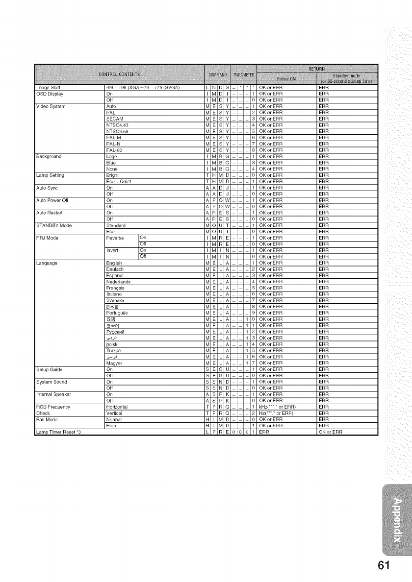
ImageShift
OSDDisplay
VideoSystem
Background
LampSetting
AutoSync
Language
SetupGuide
SystemSound
InternalSpeaker
RGBFrequency
-96 +96 (XGA)/-75 +75(SVGA)
On
Off
Auto
PAL
SECAM
NTSC4.43
NTSC3.58
PAL-M
PAL-N
PAL-60
Logo
Blue
None
Bright
Eco + Quiet
On
Off
On
Off
On
Off
Standard
Eco
Reverse On
Off
Invert On
English
Deutsch
Espa_lo[
Nederlands
Francais
Italiano
Svenska
B;_
Portugu6s
PYCCK_4_
)olski
TQrk£e
Magyer
On
Off
On
Off
On
Off
Horizontal
Vertical
Normal
High
61
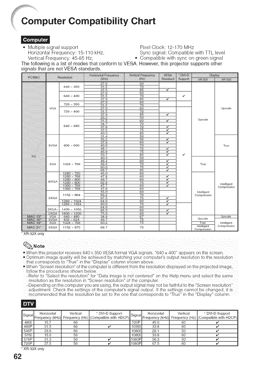
[Computer Compatibility Chart
o Multiple signal support Pixel Clock: 12-170 MHz
Horizontal Frequency: 15-1 10 kHz, Sync signal: Compatible with TTL level
Vertical Frequency: 45-85 Hz, ,, Compatible with sync on green signal
The following is a list of modes that conform to VESA. However, this projector supports other
signals that are not VESA standards.
i!iiiiiiiiiiiiiiii!il;_iii!ii_i_ii!iiiiiiiiiiiii!llll_iilllllll_l_l_illlilliilliilll_lii_i_i_!l_!ii_IliIliIliIlillilllllliilillllllilllil!!!iii_iii!_!iii!ii!i;ii!i!i;ii!i!ii!_¸!]iii!iiiiiiiiiiiiiiiiiiiiiiiiiiiiiiilil_;_iillllllll_llllilllllllilllll_H_lillilillllllllll_llllilllllllilllll1_'_lil__i_iii ¸ i!ii!iiiiiiiiii!ii_!_i!_iiiii!ii!iiiiiiiiiii!ii!!!!i_i!!iii!iii_!_£_Siiiiiiiiiiiiiill
27.0 60
640 × 350 31.5 70
37.5 85 v'
27.0 60
640 × 400 31.5 70 v'
37.9 85 J
27.0 60
720 × 350 31.5 70
VGA 27.0 60 Upscale
720 × 400 31.5 70
37.9 85 J
26.2 80
31.8 60 J Upscale
34.7 70
640 × 480 37.9 72 J
v
37.5 75
43.3 85 v'
31.4 50
38.2 86 W
37.9 60
SVGA 800 × 600 46.6 70 True
48.1 72 V
v46.9 75
83.7 85 v v
40.3 50
48.4 60 _
XGA 1024 × 768 56.5 70 True
60.0 75 v'
68.7 85 J
1280 × 720 48.0 60
1280 × 768 47.8 60 _/
::::::::::::::::::::::::::::::::::::::::::::::::: 128o × 8oo 49.7 6o LI
WXGA 1280×800 62.8 75 v' Inteltgent
1360 × 768 47.7 60 J Compression
1366 × 768 47.8 60
85.0 60 Inteligent
1152 × 864 66.2 70 Compression
SXGA 67.8 75 J
1280 × 1024 64.0 60 v
1280 × 1024 80.0 75 v'
64.0 60
SXGA+ 1400 × 1050 65.3 60 J
vUXGA 1600 × 1200 78.0 60
VGA 640 × 480 34.9 67 Upscale
SVGA 832 × 624 49.7 75 Upscale
XGA 1024 × 768 60.2 75 True Inlelligent
SXGA 1152×870 68.7 75 Intelfgent Compression
Compression
* XR-32X only
Note
,, When this projector recel\ es 640x 350 VESA format VGA signals "640 x 400" aouears on [ne screen.
,, ODNmum image quall[y NIII De acnleveo Dy matcn _g your compu[e-'s OUtDut resolu[ion [o fne resolu[ion
[nat corresoonds to "True' -- the "Diso_ay" columr snown above.
,, When "Sc een resolution" of the computer is different from _ne resolu[ion alsplayea on [ne projec[ea image
follow the oroceaures snown DelOW
Refer 1o Select the resolution" for Data image is no_ centered" or" [ne Held _enu ana selec[ [ne same
resolu[ion a s [ne reso_u[ior in "Sc -een resolution" of the con :)u[er.
Depenalng on -[necomDu[er you are using -[neou[uu[ s_gnal may not be faithful to the "Screer resolu[ion
aa Jstment. Check the sei[ings )f the comuuter's s gnal OU[DUt. If the setting s canno_ De changed, [ _s
recommenaea zna[ [ne resolution De se[ 1o _ne one [na[ corres 3onas 1o "True" in the "Dis Dis/" column.
Horizontal
Signal Frequency(kHz)
4801 15.7
480P 31.5
540P 33.8
5761 15.6
576P 31.3
720P 37.5
* XR-32X only
62
Vertical * DVI-D Support Signal Horizontal
Frequency(Hz) (Compatible with HDCP Frequency(kHzl
60 720P 45.0
60 _ 1035| 33.8
60 10801 28.1
50 1080| 33.8
50 _ 1080P 56.3
50 _ 1080P 67.5
Vertical * DVI-D Support
Frequency (Hz) (Compatible with HDCP
6O i*/
6O i*/
5O i*/
6O i*/
5O i*/
6O
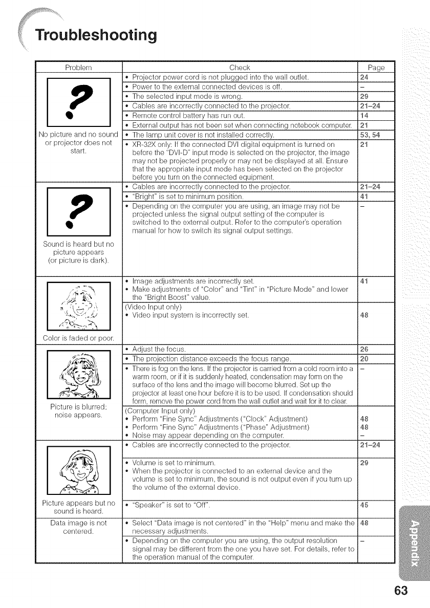
Problem Page
24
No picture and no sound
or projector does net
start.
Sound is heard but no
picture appears
(or picture is dark).
Color is faded or poor.
Picture is blurred;
noise appears.
Check
• Projector power cord is not plugged into the wall outlet.
• Power to the external connected devices is off.
• The selected input mode is wrong. 29
• Cables are incorrectly connected to the projector. 21-24
• Remote control battery has run out. 14
• External output has not been set when connecting notebook computer. 21
• The lamp unit cover is not installed correctly. 53, 54
• XR-32X only: If the connected DVI digital equipment is turned on 21
before the "DVI-D" input mode is selected on tile projector, tile image
may not be projected properly or may not be displayed at all. Ensure
that tile appropriate input mode has been selected on the projector
before you turn on the connected equipment.
• Cables are incorrectly connected to the projector. 21-24
, "Bright" is set to minimum position. 41
• Depending on the computer you are using, an image may net be
projected unless the signal output setting of the computer is
switched to the external output. Refer to the computer's operation
manual for how to switch its signal output settings.
• Image adjustments are incorrectly set. 41
• Make adjustments of "Color" and "Tint" in "Picture Mode" and lower
the "Bright Boost" value.
(Video Input only)
• Video input system is incorrectly set. 48
• Adjust the focus.
• The projection distance exceeds the focus range.
• There is fog on the lens. If the projector is carded from a cold room into a
warm room, or if it is suddenly heated, condensation may form orsthe
surface of the lens and the image will become blurred. Set up the
projector at least one hour before it is to be used. If condensation should
form, remove the power cord from the wall outlet and wait for itto clear.
(Computer Input only)
• Perform "Fine Sync" Adjustments ("Clock" Adjustment)
• Perform "Fine Sync" Adjustments ("Phase" Adjustment)
, Noise may appear depending on the computer.
• Cables are incorrectly connected to the projector.
26
20
• Volume is set to minimum.
• When the projector is connected to an external device and the
volume is set to minimum, the sound is not output even if you turn up
the volume of the external device.
Picture appears but no • "Speaker" is set to "Off". 45
sound is heard.
Data image is not • Select "Data image is not centered" in the "Help" menu and make the 48
centered, necessary adjustments.
• Depending on the computer you are using, the output resolution
signal may be different from the one you have set. For details, refer to
the operation manual of the computer.
48
48
21-24
29
63
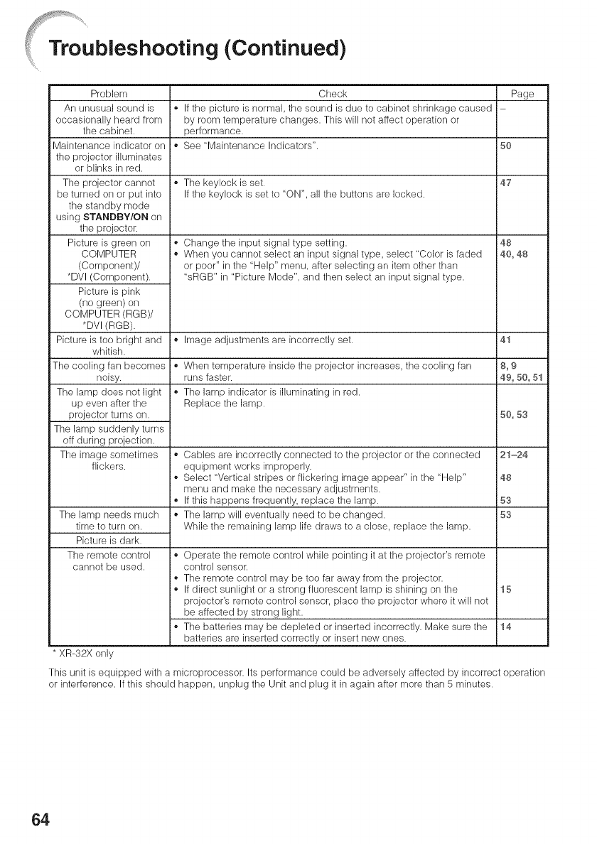
TroUbleshooting (Continued)
Problem
An unusual sound is
occasionally heard from
the cabinet.
Maintenance indicator on
the projector illuminates
or blinks in red.
The projector cannot
be turned on or put into
the standby mode
using STANDBY/ON on
the projector.
Picture is green on
COMPUTER
(Component)/
*DVl (Component).
Picture is pink
(no green) on
COMPUTER (RGB)/
*DVI (RGB).
Picture is too bright and
whitish.
The cooling fan becomes
noisy.
The lamp does not light
up even after the
projector turns on.
The lamp suddenly turns
off during projection.
The image sometimes
flickers.
The lamp needs much
time to turn on.
Picture is dark.
The remote control
cannot be used.
Check Page
,,If the picture is normal, the sound is due to cabinet shrinkage caused
by room temperature changes. This will not affect operation or
performance.
• See "Maintenance Indicators". 50
The keylock is set. 47
If the keylock is set to "ON", all the buttons are locked.
Change the input signal type setting. 48
When you cannot select an input signal type, select "Color is faded 40, 48
or poor" in the "Help" menu, after selecting an itern other than
"sRGB" in "Picture Mode", and then select an input signal type.
,,Image adjustments are incorrectly set. 41
,,When temperature inside the projector increases, the cooling fan 8, 9
runs faster. 49, 50, 51
The lamp indicator is illuminating in red.
Replace the lamp. 50,53
,,Cables are incorrectly connected to the projector or the connected 21-24
equipment works improperly.
Select "Vertical stripes or flickering image appear" in the "Help" 48
menu and make the necessary adjustments.
,,If this happens frequently, replace the lamp. 53
,,The lamp will eventually need to be changed. 53
While the remaining lamp life draws to a close, replace the lamp.
,,Operate the remote control while pointing it at the projector's remote
control sensor.
The remote control may be too far away from the projector.
If direct sunlight or a strong fluorescent lamp is shining on the 15
projector's remote control sensor, place the projector where it will not
be affected by strong light.
The batteries may be depleted or inserted incorrectly. Make sure the 14
batteries are inserted correctly or insert new ones.
* XR-32X only
This unit is equipped with a microprocessor. Its performance could be adversely affected by incorrect operation
or interference. If this should happen, unplug the Unit and plug it in again after more than 5 minutes.
64

For SHARP Assistance
if you encounter any problems during setup or operation of this projector, first
refer to the "Troubleshooting" section on pages 63 and 64. if this operation manual
does not answer your question, please contact the SHARP Service departments
listed below.
Canada
Mexico
U.S.A. SharpElectronicsCorporation Benelux SNARPElectronicsBenelu×BV1-888-GO-SHARP (1-888-467-4277) 0900-SHARPCE (0900-7427723)
Icdsupport@sharpsec.com Nederland
http://www.sharpusa.com 9900-0159 Belgium
http://www.sharp.nl
Sharp Electronics of Canada Ltd. http://www.sharp.be
(905) 568-7140 http://www.sharp.lu
http://www.sharp.ca
Australia Sharp Corporation of Australia Pty.
Sharp Electronics Corporation Ltd.
Mexico Branch 1300-135-022
(525) 716-9000 http://www.sharp.net.au
http://www.sharp.com.mx
Latin America
Germany
U.K.
Italy
France
Spain
Switzerland
Sharp Electronics Corp. Latin
American Group
(305) 264-2277
www.servicio@sharpsec.com
http://www.siempresharp.com
Sharp Electronics (Europe) GMBH
01805-234675
http://www.sharp.de
i ii
Sharp Electronics (U.K.) Ltd.
08705 274277
http://www.sharp.co.u k/customersupport
Sharp Electronics (Itamy) S.P.A.
(39) 02-89595-1
http://www.sharp.it
Sharp Electronics France
01 49 90 35 40
hotlineced@sef.sharp-eu.com
http://www.sharp.fr
Sharp Electronica Espana, S.A.
93 5819700
sharplcd@sees.sharp-eu.com
http://www.sharp.es
Sharp Electronics (Schweiz) AG
0041 1 846 63 11
cattaneo@sez.sharp-eu.com
http://www.sharp.ch
Sharp Electronics ( Nordic )AB
(46) 8 6343600
vision .support@sen .sharp-eu .corn
http://www.sharp.se
Sharp Electronics (Europe) GMBH
Branch Office Austria
0043172719123
pogats@sea.sh arp-eu.com
http://www.sharp.at
New Zealand
Singapore
Hong Kong
Taiwan
Malaysia
U.A.E.
Thailand
Korea
india
Sharp Corporation of New Zeamand
Phone: (09) 573-0111
Fax: (09) 573-0112
http://www.sharp.net.nz
Sharp-Roxy Sames is) Pte. Ltd.
65-226-6556
ckng@srs.global.sharp.co.jp
http://www.sharp.com.sg
Sharp-Roxy (HK) Ltd.
(852) 2410 2623
dcmktg@srh.global.sharp.co.jp
http://www.sharp.com.hk
Sharp Corporation (Taiwan)
0800-025111
http://www.sharp-scot.com.tw
Sharp-Roxy Sales & Service Co.
(60) 3-5125678
Sharp Middle East Fze
971-4-81-5311
helpdesk@smef.global.sharp.co.jp
Sharp Thebnakorn Co. Ltd.
02-236-0170
svc@stcl.global.sharp.co.jp
http://www.sharp-th.com
Sharp Electronics Incorporated of
Korea
(82) 2-3660-2002
Icd@sharp-korea.co.kr
http://www.sharpkorea.co.kr
Sharp Business Systems (India)
Limited
(91)11-6431313
service@sharp-oa.com
Sweden
Austria
!i! _ii i
i I ii i
_iii_i_i_:i_
65
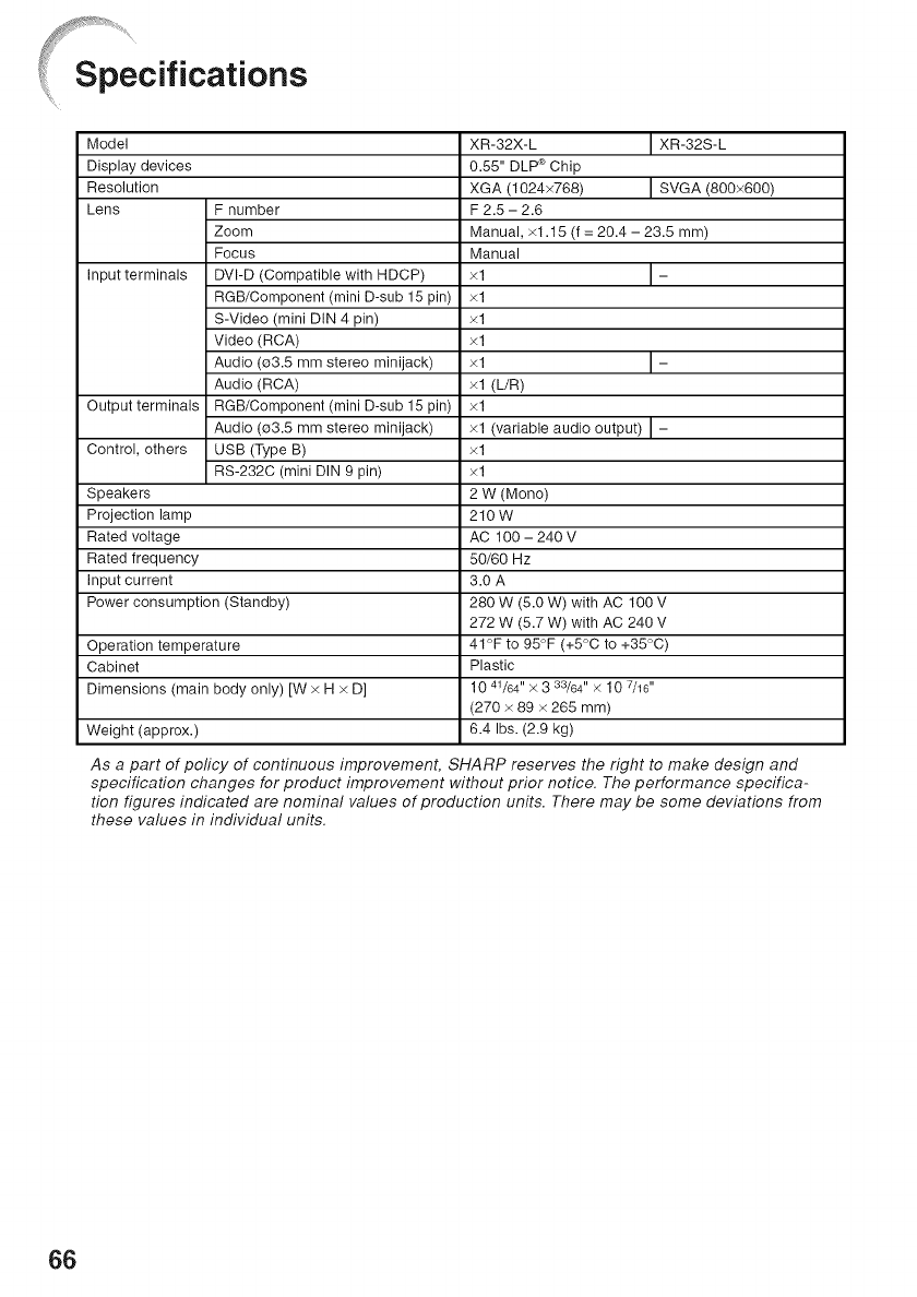
Model
Display devices
Resolution
Lens
Input terminals
Output terminals
Control, others
Speakers
Projection lamp
Rated voltage
Rated frequency
Input current
Power consumption (Standby)
Operation temperature
Cabinet
Dimensions (main body only) [W x H x D]
Weight (approx.)
F number
Zoom
Focus
DVI-D (Compatible with HDCP)
RGB/Component (mini D-sub 15 pin)
S-Video (mini DIN 4 pin)
Video (RCA)
Audio (03.5 mm stereo minijack)
Audio (RCA)
RGB/Component (mini D-sub 15 pin)
Audio (03.5 mm stereo minijack)
USB (Type B)
RS-232C (mini DIN 9 pin)
XR-32X-L I XR-32S-L
0.55" DLP _>Chip
XGA (1024x768) I SVGA (800x600)
F 2.5 - 2.6
Manual, x1.15 (f = 20.4 - 23.5 mm)
Manual
xl I-
xl
xl
xl
xl I-
xl (L/R)
xl
xl (variable audio output) I -
xl
xl
2W (Mono)
210W
AC 100 - 240 V
50/60 Hz
3.0 A
280 W (5.0 W) with AC 100 V
272 W (5.7 W) with AC 240 V
41°F to 95°F (+5°C to +35°C)
Plastic
1041/64 '' × 3 33/64" X 10 Z/16 ''
(270 x 89 x 265 mm)
6.4 Ibs. (2.9 kg)
As a part of peficy of continuous improvement, SHARP reserves the right to make design and
specification changes for product improvement without prior notice. The performance specifica-
tion figures indicated are nominal values of production units. There may be some deviations from
these values in individual units.
66
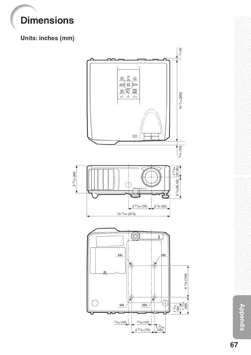
Units: inches (ram)
_t_ r
X
o
10 41/64 (270)
.....N_ .....
Ws2 (10)_.1
I
27/64
',36)_
i i i_ii
ii_i iii ii
! i_{i
67
L-CLICK/EFFECT button .................................. 32_ 34
Lens Cap ................................................................. 11
MAGNIFY buttons ................................................... 33
MENU/HELP button .......................................... 38_ 48
MONITOR OUT terminaJ ......................................... 23
MOUSE/Adjustment buttons ............................. 3& 38
NORMAL ........................................................... 30_ 31
ON button ................................................................ 25
Optional accessories ............................................... 10
OSD Display ............................................................ 43
PAGE DOWN button ................................................ 34
PAGE UP button ...................................................... 34
PDF ............................................................................ 9
Picture Adjustment .................................................. 40
Picture Mode ..................................................... 33_ 40
PICTURE MODE button .......................................... 33
POINTER button ..................................................... 32
Power cord ............................................................... 24
Power indicator ........................................................ 50
PRJ ADJ ................................................................ 45
PRJ Mode .......................................................... 19_ 44
Progressive .............................................................. 42
R-CLICK/RETURN button ................................. 34_ 38
Rear adjustment foot ............................................... 27
Red .......................................................................... 41
Remote control ........................................................ 13
Remote control sensor ............................................ 15
Replacing the lamp ........................................... 52_ 53
Resize ................................................................ 30_ 43
RESIZE button ........................................................ 30
RGB cable ............................................................... 21
RS 2320 terminal .................................................... 24
SCR ADJ ............................................................... 43
Screen Size and Projection Distance ..................... 20
Setup (_uide ....................................................... 2& 44
Sharp ....................................................................... 41
Speaker ................................................................... 4B
SPOT button ............................................................ 32
STANDBY button ..................................................... 25
STANDBY Mode ...................................................... 45
STANDBY/ON button .............................................. 25
STRETCH .......................................................... 30_ 31
Supplied accessories .............................................. 10
SVDEO button ....................................................... 29
S VIDEO terminal .................................................... 22
System Lock ............................................................ 46
System Sound ......................................................... 45
Temperature warning indicator ............................... 50
Tint ........................................................................... 41
USB terminal ........................................................... 34
VIDEO button .......................................................... 29
VIDEO terminal ....................................................... 22
VOL (Volume) buttons ............................................. 29
VPos ................................................................. 37_ 48
\/--STRETCH ............................................................ 31
Zoom ring ................................................................ 26
68

®
SHARP CORPORATION
