SHIFT INNOVATION DRONERACERSRX Drone Pro Racers User Manual
SHIFT INNOVATION LIMITED Drone Pro Racers Users Manual
User manual
USE R GUIDED
DPR1401
Suitable for indoor o r outdoo r whic h unde r Grad e 3 winds .
Mistakes mad e du e to negligence
of these operation instructions ma y
caus e property loss an d severe
huma n injury.
Mistakes mad e du e to
negligence of operation
instruction ma y caus e
danger .
CAUTION
FORBIDDEN
WARNIN G LABE L LEGEND
Please d o no t fly the R.C .
helicopter unde r an y
specified forbidden
environment.
WARNING
CONTENTS
Playset
Dron e Pro Racer
Li-
Po battery 3.7V 850mAh
10
Safey & Precautions
1
Battery Management
AA
-
-
-
+
+
+
AA
AA
1.5V
1.5V
1.5V
Unscre w the battery compartmen tdoo ron the underside ofthe
controllerand remove.
Insertthe battery the 3 x A A batteries (Notincluded) ensure the
+ an d - corrispond.
Insertthe battery as in the picture an d connec tthe pins together.
Insertthe battery as in the picture an d connec tthe pins together.
Insertthe battery as in the picture an d connec tthe pins together.
Insertthe battery as in the picture an d connec tthe pins together.
Insertthe battery as in the picture an d connec tthe pins together.
Insertthe battery as in the picture an d connec tthe pins together.
Insertthe battery as in the picture an d connec tthe pins together.
Insertthe battery as in the picture an d connec tthe pins together.
Insertthe battery as in the picture an d connec tthe pins together.
Insertthe battery as in the picture an d connec tthe pins together.
Insertthe battery as in the picture an d connec tthe pins together.
Insertthe battery as in the picture an d connec tthe pins together.
Insertthe battery as in the picture an d connec tthe pins together.
Insertthe battery as in the picture an d connec tthe pins together.
Insertthe battery as in the picture an d connec tthe pins together.
Insertthe batter
yas in the picture an d connec tthe pins together.
Insertthe battery as in the picture an d connec tthe pins together.
Insertthe battery as in the picture an d connec tthe pins together.
Replac e and screw the battery doo rfirmly bac k into the closed position.
1).
2).
3).
4).
Ensure thatthe controller is switched off.
Inserting Controller Batteries
Saftey
WARNING
WARNING
WARNING
CAUTION
CAUTION
CAUTION
FORBIDDEN
FORBIDDEN
FORBIDDEN
2
Battery Management
Step 1 + connec tthe battery pin to US B cable
Slide the battery compartmen tdoo r bac k to unlock and swing open.
Insertthe battery as in the picture and connec tthe pins together.
Swing closed an d slide to lock the battery doo r firmly into the closed position.
LE D status Charging status
1).
1).
1).
2).
2).
2).
3).
4).
Connec tthe US B cable to the computer
Ensure thatthe drone is switched off.
LE D is in red solid on
LE D red lightis off Charging
LE D is in red solid on Battery is Full
Powe ron
LED Charging status
Charging the Lipo dron e battery
Connectin g the Lipo battery to the Dron e RacerConnectin g the Lipo battery to the Dron e Racer
Please pa y attention to the following
(1)During charging,the charge r should b e pu tin dry and ventilated place an d far awa y from hea tsource an inflammable an d explosive substance.
(2)Only used to charging 2S Li-ion or Li-polymerbattery pac k .ifnot ,the charge r orbattery ma y b e damage d .
(3)Neve rleave the charge runsupervised during the proces s ofcharging in orderto avoid risk ofaccidents.
(4)Neve rimmediately charg e yourbattery pac k as soo n as the flightis finished
,orwhe n its temperature doesn’tcoo ldow n .otherwise the battery willtake a risk in swelling
,even a fire.
(5)Ensure the correctness ofpolarity before connection the battery to charger.
(6)Avoid drop an d violence during the process ofcharging .drop and violence willresultin internalshortcircuitofthe battery.
(7)Forthe sake ofsafety ,please use originalcharging equipmen tand battery pac k .please chang e ne w one in time whe n the flying time is becomin g shorten du e to long
time usag e .
(8)Ifitis retained in the charge rfor a long time aftersaturated,the battery ma y automatically discharge.Whe n the charge r detects thatthe voltage ofindividualcells is
lowerthan the rated voltage,itwillre-charge untilsaturated.Frequentl
y charging an d discharging willshorten the lifetime ofyour battery pac k .Itis advised thatplease cu toff
the powe rand took offthe battery afterthe charging is saturated.
5.Maintenance ofbattery pack
(1)The battery pac k should b e pu tin dry and ventilated place.The storage temperature ofenvironmen tisrange d from 18°C to 25°C.
(2)Please avoid frequentcharging an d excessive discharging the battery pac k in order to prolong its life cycle.
(3)Itis a mus tto maintain the battery pac k before long-term storage.Tha tis to charge the battery to the levelof50-60% saturation.
(4)Ifthe storage term is ove r1 month ,itis advised to monthly chec k the voltage ofevery cellofthe battery pack. The voltage ofevery cellshould be no tless than 3V.
Otherwise,please refer to the abov e article
(3).
(5)From the view pointofprotection,ne w battery pac k should b e motivated before usage .Tha tis to charge and discharge 3-5 times,bu tdischarge is no tless than the
levelof70% saturation.This proces s willmak e the battery lifetime longeran d voltage mor e stable.
1). 2). 3). 4).
O N /OFF
Downloa d an d installthe app
Us e the corrisponding Q R cod e to downloa d and installthe releventapp.
Th e ControllerTh e Controller
TAK E PHOTO
SEE "ADJUSTING
TRIM
DIRECTION
CONTROL
POWER
ON/OFF
?
RECORD
VIDEO
TAK E OF F /
LANDING
CHANG E SKILL /
SPEE D LEVEL
DEVIC E ATTACHMENT
RELEAS E PIN
CHANG E LED
COLOUR
THROTTL E AND
PIVO T JOYSTICK
ADJUS T DEVICE
ANGLE
4).
Setup
3
Playset Asembley
1. 1.
2. 2.
3. 3.
Slide the battery compartmen tdoo r bac k to unlock and swing open.
Insertthe battery as in the picture and connec tthe pins together.
1).
2).
3).
Ensure thatthe drone is switched off.
Chequre d Flag Finish Turn chec k markers
QR
CODE
QR
CODE
4
Setup
s
Navigation
SELEC T STANDAR D UI
OPEN
CONTROLLE R UI
LED COLOUR
CHANGE
TAK E PICTURE
SPEE D CONTROL
CAN T REMEMBER
RECOR D VIDEO
OPE N OPEN
IMAGE S AN D VIDEO
FLIP TH E UI CLOSE
CONTROLLE R UI
BACK
DIRECTIONAL
JOYSTICK
FORWAR D /
BACKWARD
TRIM
LEFT / RIGHT
TRIM
1 BUTTO N LANDING
THROTTLE
AN D PITCH
1 BUTTON
TAK E OFF
BACK
PRES S TO SELECT
V R HEADSE T UI
R L
1
3
2
Th e App
Conecting you r device to the RACER
1).
Ensure thatthe device wifiis switched on.
Find the drone the nam e willbegin with "DPR-"an d connect.
Ifmultiple players are trying to connec tto severaldrone take itin turns to ensure correctpairing.
2).
3).
Flight
7
Adjusting Trim
Whilst the drone is hovering,press the opposite button to the
direction ofdrone movemen tuntilyourdrone hovers stabley in
place.
Ensure this is don e with no win d disturbance.
Attaching the device to the controller
Slide the device holder ove rthe coloured antenna untilitclicks firmly into place.
Fix your device firmly into place betwee n the spring loaded grips.
Adjustthe view angle to suityou rpersona lpreference via the wheel
ensuring to tighten fully.
1).
2).
3).
4).
Ensure thatthe drone is switched off.
Pro Tips
Whilst the drone is hovering,press the opposite button to the
direction ofdrone movemen tuntilyourdrone hovers stabley in
place.
Propellers
Unscre w an d remov e the damadge d propeller.
Securely screw the new propellerin place.
Slide on the new propellerensuring itis the sam e as the one
removed.
1).
2).
4).
3).
Ensure thatthe drone an d controller are switched off.
Propeller Guards
The attached beginerpropellerguard s and bod y kitpanels are there to protectthe
drone from damadg e in the even tofan acciden tan d as a saftey precaution to protect
others from the fastmovin g blades.
The guard s should be kep ton whe n flying in any public place.
Should an expeirenced pilotwish to remov e them ,atthierow n risk,for the added
performanc e whilstflying in an enclosed area awa y from others.
1).
2).
Ensure thatthe drone an d controller are switched off.
Replacemen t Parts
9
Bod y Kit
Align the bod y kitpane lor shellwith the snap pins on the blade guard s orrollcage . .
Apply a little pressure untilthe pane lor bod y kitsnap firmly into place.
1).
2).
3).
Ensure thatthe drone an d controller are switched off.
Unscre w an d remov e the propellerguard as indicated in the diagram.
Set Up
8
Navigation
TAK E PICTURE
RECOR D VIDEO
OPE N OPEN
IMAGE S AN D VIDEO
CLOSE
CONTROLLE R UI
R L
3
Recording the Live video stream
To startorstop recording video from the controller simply press the button indicated in the diagram below.
To startrecording from the ap p U Iope n the controller an d press the button as indicated in the diagram below.
Video and Image s can b e accesse d via the ap p folder icon (indicated below )or found in the devices camer a roll
wher e they ca n b e viewd and shared onine.
1).
2).
3).
3).
the FP V stream ca n be captured as both stills or video via the controller buttons or the Ap p UI.
OPEN
CONTROLLE R UI
TAK E PHOTO
RECORD
VIDEO
Trouble shooting
7
PROBLEM CAUSE SOLUTIONS
Afterthe battery is inserted
in the heli,indicatorlight
on receiver keep s flashing,
no response to operations
N o respons e after battery is
inserted in the heli
Moto rdoe s no trun when
operating the throttle stick
and the indicator lighton
receiverkeep s flashing
Main moto r blade spins but
heliwon’tfly
Helishake s a lot
Turning trimmerhas been
tried bu thelistillspins,
spee d to the rightan d left
doe s no tconform
Itwon’tfly after itfalls
down
Frequenc y adjusting between
remote and receivernot
successful
Readjus tfrequency forremote
and receiver.(please refer to P.7
for details)
1.check ifthe powe rfor
remote an d receiveris on
2.check the voltage ofthe
batteries ofremote and
receive
3.contacton the poles are
notgood
1.open the transmitterand make
sure ifthe battery is inserted
in rightposition
2.use a fully charge d battery
3.reinstallthe battery and
confirm ifthe contactfor
the pole is o
1.main blade ha s deformed
2.motor doe s notwor k wel
1.motor has droppe d off
2.gear has loosened
1.reinstallthe motor
2.tighten the gear
1.replace mai n blade
2.replace mai n motor
1.the blade ha s deformed
2.battery powe ris not
enough
1.replace the main blade
2.replace the main frame
1.replace the main blade
2.charge the battery orreplace
itwith a fully charge d battery
Powe r forthe Li-Poly batter
is notenough
Charg e the battery orreplace it
with a fullbattery
1.main blade ha s deformed
2.main frame ha s deformed
Turn on the heliand center the
climbing and diving trimmer then
restartthe heli
Cente ron the gyro is not
correct
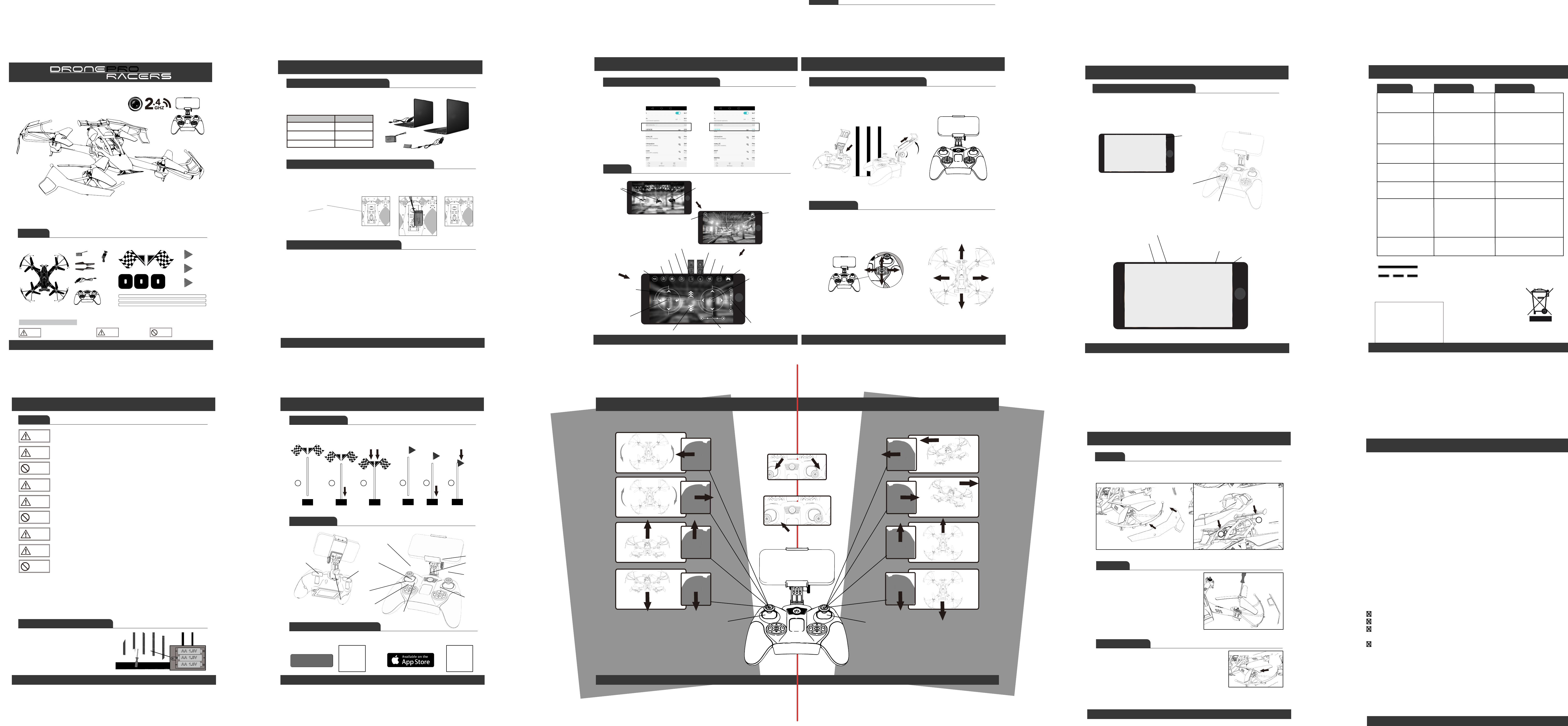
Flight Controls
65
Start Engines
Turn On the racer
and controller
Direction Joystick
Tilt
Backw
ards
Tilt
Backw
ards
Tilt
Forwar
ds
Tilt
Forwar
ds
Forwar
ds
Backw
ards
Tilt
Right
Tilt
Right
Turn Right
Right
Left
Pivot
Pivot
Tilt
Left
Tilt
Left Turn
Left
Down
Up
Throttle and Pivot
Take Off
See "Set Up" to view
realtime video stream
See "App UI" to view record the
video stream
Ensure thatthe drone is switched off. Ensure thatthe drone is switched off.
RECYCLING
This product bears the selective sorting symbol for Waste electrical and
electronic equipment (WEEE). This means that this product must be
handled pursuant to European directive 2012/19/EU in order to be recycled
or dismantled to minimize its impact on the environment.
User has the choice to give his product to a competent recycling organization
or to the retailer when he buys an new electrical or electronic equipment.
CAUTION
RISK OF EXPLOSION IF BATTERY IS REPLACED
BY AN INCORRECT TYPE.
DISPOSE OF USED BATTERIES ACCORDING
TO THE INSTRUCTIONS
DC voltage
Warning: Changes or modifications to this unit not expressly approved by the
party responsible for compliance could void the user’s authority to operate the
equipment.
NOTE: This equipment has been tested and found to comply with the limits for
a Class B digital device, pursuant to Part 15 of the FCC Rules. These limits are
designed to provide reasonable protection against harmful interference in a
residential installation. This equipment generates, uses and can radiate radio
frequency energy and, if not installed and used in accordance with the
instructions, may cause harmful interference to radio communications.
However, there is no guarantee that interference will not occur in a particular
installation. If this equipment does cause harmful interference to radio or
television reception, which can be determined by turning the equipment off and
on, the user is encouraged to try to correct the interference by one or more of the
following measures:
Reorient or relocate the receiving antenna.
Increase the separation between the equipment and receiver.
Connect the equipment into an outlet on a circuit different from that to which
the receiver is connected.
Consult the dealer or an experienced radio/TV technician for help.
This device complies with Part 15 of the FCC Rules. Operation is subject to the
following two conditions : (1) this device may not cause harmful interference, and
(2) this device must accept any interference received, including interference that
may cause undesired operation.
FCC RF exposure statement:
“FCC RF Radiation Exposure Statement Caution: To maintain compliance with
the FCC’s RF exposure guidelines, place the product at least 20cm from
nearby persons.” “The device must not be co-located or operating in conjunction
with any other antenna or transmitter.”
This device complies with Part 15 of the FCC Rules. Operation is subject to the following
two conditions : (1) this device may not cause harmful interference, and (2) this device
must accept any i nterference received, including interference that may cause
undesired operation.