SII Data Service SA-4320 Order Entry System Handheld Terminal User Manual 2
SII Data Service Corporation Order Entry System Handheld Terminal 2
Contents
- 1. user manual 1
- 2. user manual 2
user manual 2
SA-4320
Handheld Terminal
Instruction Manual
U00104848701
Read this manual carefully before using the device, use the
device correctly, and keep this manual for future reference.
Caution
To reduce the risk of injury and damage to the device, read
and understand the “Safety Precautions” in this manual.

This equipment has been tested and found to comply with the limits for a Class B digital device, pursuant to Part 15 of the
FCC Rules. These limits are designed to provide reasonable protection against harmful interference in a residential
installation. This equipment generates, use and can radiate radio frequency energy and, if not installed and used in
accordance with the instructions, may cause harmful interference to radio communications. However, there is no guarantee
that interference will not occur in a particular installation.
If this equipment does cause harmful interference to radio or television reception, which can be determined by turning the
equipment off and on, the user is encouraged to try to correct the interference by one or more of the following measures:
--Reorient or relocate the receiving antenna.
--Increase the separation between the equipment and receiver.
--Connect the equipment into an outlet on a circuit different from that to which the receiver is connected.
--Consult the dealer or an experienced radio/TV technician for help.
WARNING
You are cautioned that changes or modifications not expressly approved by the party responsible for compliance could void
your authority to operate the equipment.
CAUTION
This equipment complies with FCC radiation exposure limits set forth for an uncontrolled environment. End-users must follow
the specific operating instructions for satisfying RF exposure compliance.
This transmitter must not be co-located or operating in conjunction with any other antenna or transmitter.
U00090440800 March 2007
U00090440801 July 2007
©SII Data Service Corp. 2007
All rights reserved.
The contents of this reference may change without notice.
is a registered trademark of Seiko Instruments Inc.
Linux is a trademark or registered trademark of Linus Torvalds and associates in the United States and other countries.
The screen fonts used by this product belong to Ricoh corporation.
Dispose of the device according to the regulations of your local government.
For details, consult your local government.
i
Introduction
This manual explains how to operate the SA-4320 Handheld Terminal (the “device”)
and the Handheld Terminal operating system (the “Handheld Terminal OS”) that is
operated with the device.
Read the “Safety Precautions” before using the device, use the device correctly and
safely, and keep this manual for future reference.
This manual consists of seven chapters and appendices. The main contents are
described below.
Chapter 1 Explains the device characteristics, components, and features. The
system described here is composed of the SA-1320 Wireless Station
(the “Wireless Station”) and the SA-2330 Wireless Repeater (the
“Wireless Repeater”).
See relevant manuals for detailed instructions of components.
Chapter 2 Explains prohibited actions and precautions when using the device.
Chapter 3 Explains how to insert the battery pack, which is necessary when first
using the device.
Chapter 4 Explains the functions of the device in terminal settings mode.
Chapter 5 Explains how to transfer application programs to the device.
Chapter 6 Describes solutions if an error occurs in the device.
Chapter 7 Explains the maintenance methods required to use the device in
optimum conditions.
Appendices
Describes device specifications, and the environmental conditions for
using or storing the device.
ii
Safety Precautions
Read the “Safety Precautions” before using the device, and use the device correctly
and safely.
This manual uses the following symbols to describe precautions for the correct and
safe use of the device, and to prevent damage to the equipment.
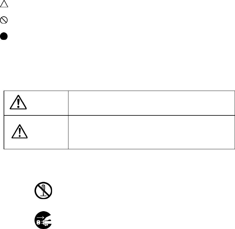
: Precautions (including danger and warning).
: Prohibited actions.
: Forced actions or instructions.
Some of these symbols with graphics indicate specific precautions, prohibitions, and
instructions as below.
Read carefully before continuing.
Warning
Warning: Indicates a potentially hazardous situation which,
if not avoided, could result in death or serious injury.
Caution
Caution: Indicates a potentially hazardous situation which, if
not avoided, could result in injury, or damage to the
equipment.
Examples of Symbols
“Do not disassemble”.
“Remove the power supply plug from the outlet”.
iii
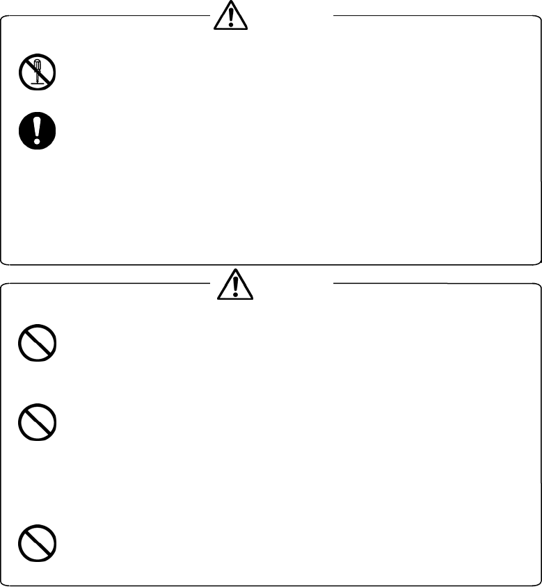
Warning
Never disassemble the device yourself.
This may result in malfunction, electric shock or fire.
Remove the battery pack immediately if the device emits abnormal
smoke, smell, or the display suddenly disappears. Keep using the
device under such conditions may cause fire.
Make sure that the device stopped smoking, and consult your local
service center for repairs.
Caution
Use only the specified battery pack with the device.
Failure to do so may result in fire or injury due to battery pack damage or
fluid leak.
Do not insert foreign objects, such as metals or liquids, into the open
vents or cracks.
This may result in malfunction, electric shock or fire.
If a foreign object should enter the device, immediately remove the
battery pack, and consult your local service center for repairs.
Do not use the device if it is malfunctioning.
This may result in electric shock or fire.
Follow all other warnings and precautions described in each section.

Contents-1
Table of Contents
Introduction i
Safety Precautions ii
Chapter 1 Overview 1-1
1.1 Characteristics 1-1
1.2 Device Components and Features 1-4
Chapter 2 Before Use 2-1
2.1 Precautions for use 2-1
2.2 Charging a Battery Pack 2-3
2.3 Carrying the Device 2-3
2.4 Storing the Device 2-4
Chapter 3 Power Supply 3-1
3.1 Turning the device on/off 3-1
3.2 Precautions for Handling a Battery Pack 3-3
3.3 Mounting and Removing a Battery Pack 3-4
3.3.1 Mounting a battery pack 3-4
3.3.2 Removing the battery pack 3-5
3.4 Reset 3-6
Chapter 4 Terminal Settings Mode Functions 4-1
4.1 Functions Overview 4-1
4.2 Startup 4-2
4.3 Functions Specifications 4-3
4.3.1 Function Menu 4-3
4.3.2 Version 4-4
4.3.3 Parameters 4-5
4.3.4 WLAN test 4-10
4.3.5 Touchscreen Calibration 4-17

Contents-2
Chapter 5 Transferring and Starting Application Programs 5-1
5.1 Downloading Application Programs 5-2
5.1.1 System ID settings 5-2
5.1.2 Transferring application programs 5-3
5.1.3 Wireless communications error 5-4
5.1.4 File transfer error 5-5
5.1.5 Firmware version upgrade 5-6
5.2 Starting Application Programs 5-7
Chapter 6 Troubleshooting 6-1
6.1 Wireless transfer failure 6-1
6.1.1 Transfer failure caused by the system (or device) , or several
Handheld Terminals are malfunctioning 6-2
6.1.2
Communication failure caused by the use of a Handheld Terminal, or
malfunction frequently occurs with a single Handheld Terminal
6-3
6.1.3 Communication failure caused by the Handheld Terminal 6-3
6.2 Nothing appears onscreen, or not properly displayed 6-4
6.3
The keypad tone does not sound, or the sound is too loud or too quiet
6-5
6.4 The system does not respond to key entries 6-5
6.5 Not properly operating 6-6
6.6 Operating time is too short 6-6
6.7
The application programs are deleted when the battery pack is replaced
6-7
6.8 The backlight does not turn on 6-7
6.9 Program runaway 6-8
6.10 LED is flashing (Orange) 6-8
Chapter 7 Maintenance 7-1
7.1 Daily maintenance 7-1
7.2 Regular maintenance 7-3
7.2.1 Replacing a battery pack 7-3
7.2.2 Service life of repeatedly charged battery packs 7-4
7.3 Replacing Parts 7-4
7.3.1 Replacing the sheet key cover 7-4
7.3.2 Replacing the sheet key unit 7-5

Contents-3
Figures
Fig. 1-1: Appearance 1 1-4
Fig. 1-2: Appearance 2 (with top cover open) 1-4
Fig. 1-3: Appearance 3 (back view) 1-5
Fig. 1-4: Battery pack appearance 1-5
Fig. 1-5: Sheet key unit appearance 1-5
Fig. 2-1: Mounting the strap 2-3
Fig. 3-1: Mounting the battery pack 3-4
Fig. 3-2: Removing the battery pack 3-5
Fig. 3-3: Reset operation 3-6
Fig. 4-1: Terminal settings mode startup 4-2
Fig. 4-2: Function Menu 4-3
Fig. 4-3: Version 4-4
Fig. 4-4: Parameters 4-5
Fig. 4-5: LCD brightness 4-6
Fig. 4-6: Buzzer 4-7
Fig. 4-7: Date/time 4-8
Fig. 4-8: Serial No. 4-9
Fig. 4-9: WLAN test 4-11
Fig. 4-10: WLAN test (Specifying destination) 4-12
Fig. 4-11: WLAN test (Specifying channel) 4-13
Fig. 4-12: WLAN test (Testing) 4-14
Fig. 4-13: WLAN test (Results screen 1) 4-15
Fig. 4-14: WLAN test (Results screen 2) 4-16
Fig. 4-15: Touchscreen Calibration 4-17
Fig. 5-1: System ID settings 5-2
Fig. 5-2: Transferring apprication programs 5-3
Fig. 5-3: Cannot communicate with the Wireless Stations 5-4
Fig. 5-4: File transfer error 5-5
Fig. 5-5: Firmware version upgrade 5-6
Fig. 7-1: Device rails 7-2
Fig. 7-2: Battery pack rails 7-2

1-1
Chapter 1 Overview
This chapter explains the device characteristics, components and features.
1.1 Characteristics
This device is a data input device used for Order Entry Systems. A network with the
host computer and POS terminal using a Wireless Station enables a wide range of
applications and advanced Order Entry System features.
The device has the following features:
(1) Excellent portability and operationality
Compact design that fits in your pocket. The device is easy to carry and can be
used anywhere and any time.
(2) Many display functions
A TFT color liquid crystal panel is built-in that enables a maximum of 256 colors to
be displayed simultaneously. The display abilities are as follows: 15 columns x 20
rows of double-byte characters (16 x 16 dots), 30 columns x 20 rows of
single-byte characters (8 x 16 dots), 10 columns x 13 rows of double-byte
characters (24 x 24 dots), and 20 columns x 13 rows of single-byte characters (12
x 24 dots). Double-byte and single-byte characters can also be mixed.
(3) Wireless communications functions
This is a wireless facility that conforms to low-power data communications
systems (RCR STD-33 and ARIB STD-T66).
This function enables the immediate transfer of data entered in the device to the
Wireless Station.
1-2
(4) Built-in touchscreen
The device’s built-in touchscreen offers excellent operationality. Touch the display
directly and select the required menu.
(5) Available in a wide range of environments
A connecter is not required for communications between the device and the
Wireless Station. The device is designed with excellent waterproof and dustproof
properties.
(6) Built-in backlight
The built-in backlight with a luminosity adjustment function enables settings for
optimum brightness from light to dark.
(7) Auto power OFF function
To minimize battery consumption, the device is designed to turn off automatically
after certain period of time passes without any input.
Press any key or touch the screen to turn it on again.
(8) Backup function
The built-in backup battery saves memory data when the battery pack is being
replaced.
(9) Resume (auto recovery) function
Operations will be suspended if the battery pack voltage drops while the device is
being used. Insert a charged battery for auto recovery.
(10) Uses the Linux operating system
The device uses the Linux OS as the operating system.
(11) Uses a battery pack
The device uses a rechargeable SA-4003-01 battery pack. The actual battery life
depends on the application programs used and the use environment, but a
fully-charged battery pack can be used for about 1 day.
A dedicated SA-5320 charger is required for charging.
Chapter 1: Overview
1-3
(12) Functions tailored to user purposes
The majority of device functions are determined by the application program, so
the user can install the device functions suited to their purpose.
(13) Built-in 3-color LED
The built-in 3-color (green, red, and orange) LED on the upper surface of the
device indicates status including wireless data transfer and errors.
(14) Replaceable sheet key unit
The device has a removable sheet key unit, which allocates menus in the device.
The device can be operated with or without the sheet key unit.
The sheet key unit is a consumable. Replace the SA4004-00 sheet key unit if it
malfunctions in order to continue using the device.
1-4
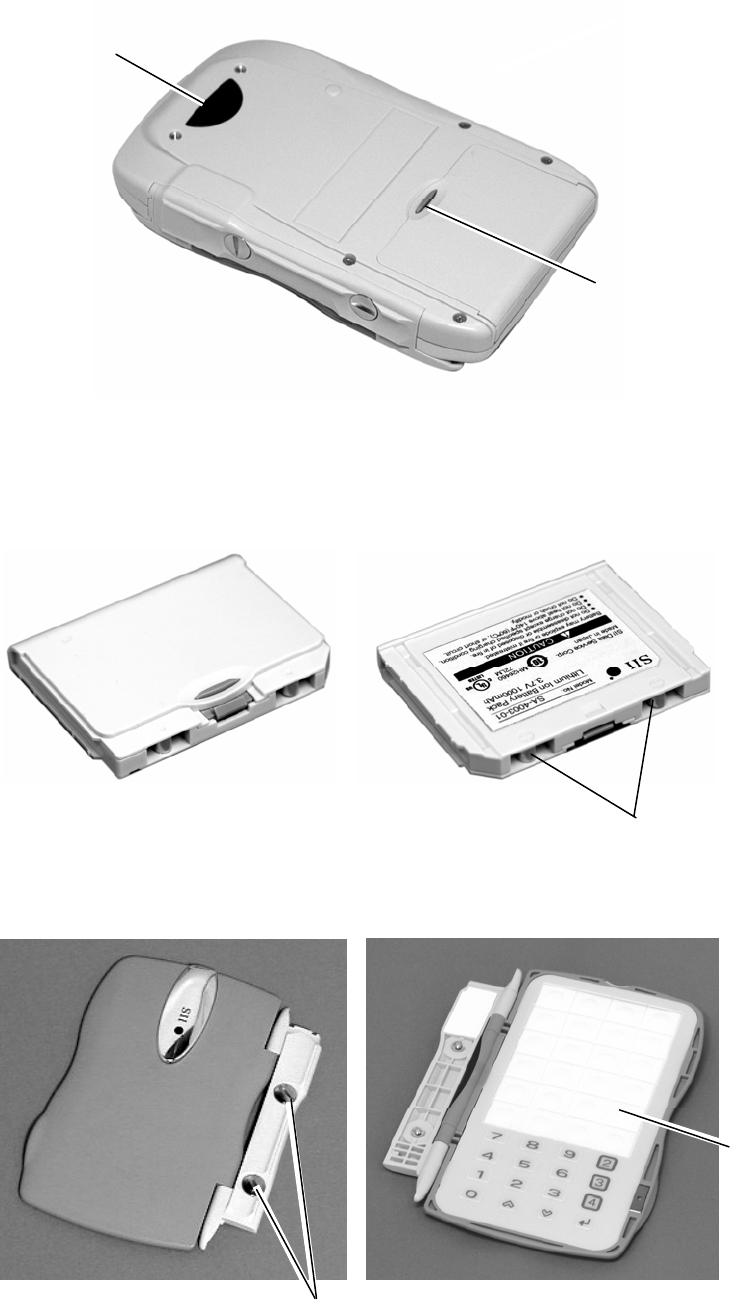
1.2 Device Components and Features
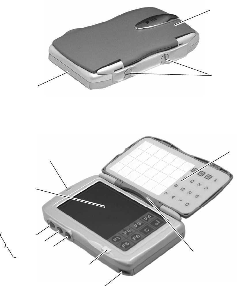
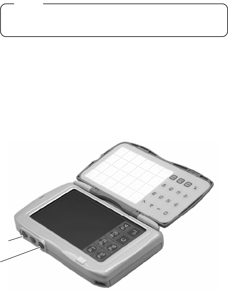
Fig. 1-1 shows view from the front, Fig. 1-2 shows view with the top cover open, and
Fig. 1-3 shows view from the back. Fig. 1-4 shows the battery pack components and
features, and Fig. 1-5 shows the sheet key unit components and features.
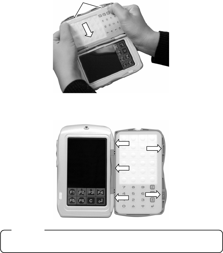
Fig. 1-1: Appearance 1
Fig. 1-2: Appearance 2 (with top cover open)
Touchscreen
Sheet key cover
Magnet
Hinge
LED
Battery pack
Sheet key unit
Coin screws
Scroll UP key
Strap stopper
Scroll DOWN key
Enter key
Side keys
Chapter 1: Overview
1-5
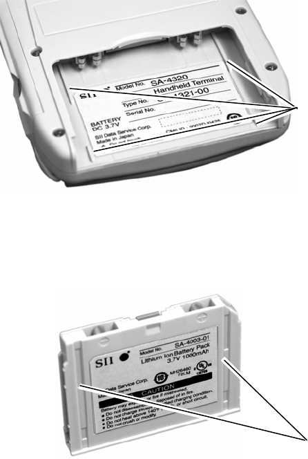
Fig. 1-3: Appearance 3 (back view)
Fig. 1-4: Battery pack appearance
Fig. 1-5: Sheet key unit appearance
Battery pack
eject button
Battery terminals
Infrared
communications
port
Sheet key cover
Coin screws

2-1
Chapter 2 Before Use
This chapter explains the prohibitions and precautions when using the device.
To always use the device in its proper state, follow all the instructions below without
fail. Failure to do so may cause malfunction or damage. SII Data Service Corp. takes
no responsibility for damage caused by use of the device that does not comply with
proper usage outlined in this manual.
2.1 Precautions for use
(1) Never alter or modify the device. The device has a built-in wireless facility that has
received technical standard compliance certification according to the Radio Law.
Using illegally modified devices may be punishable under the Radio Law.
(2) Take care not to drop, bend, or strongly shock the device, as the device has a
highly-sensitive wireless facility built-in. Contact your local service center if the
device is damaged in an accident or is dropped during use. Never get the device
repaired anywhere other than the service center.
(3) Do not place objects or rest your hand on the device.
(4) Do not place food or drinks, such as coffee, or hot objects such as cigarettes, on
the device.
(5) Do not wash or pour liquids, such as water or oil, over the device. It is not
waterproof.

2-2
(6) Never store or leave the device in any of the following locations. This may result in
case deformation or device malfunction, such as reduced or deteriorated battery
performance, or memory loss.
・ Locations with temperatures below 5°C
・ In vehicles during summer
・ Locations near air-conditioning equipment
・ Locations with direct sunlight
・ Locations with temperatures higher than 40°C
(7) Avoid using the device in the following locations:
・
Locations with magnetic fields (i.e., near microwave ovens, electromagnetic
cookers, industrial refrigerators, ice makers, devices with built-in motors.)
・ Locations surrounded by conductive materials, such as metals
・
Locations near high-temperature devices, such as microwave ovens and
electrotherms
・ Locations potentially exposed to moisture or water vapor
・ Locations with severe environmental changes in temperature and humidity
・ Locations where corrosive gasses or saline may be generated
・ Dusty or dirty locations
・ Locations where vibration occurs
・ Locations with direct sunlight
(8) Do not press the sheet keys, side keys, or touchscreen with sharp or hard objects,
such as a ballpoint pen. This may result in malfunction. Operate the device with
your fingers, and do not press forcefully with fingernails.
(9) Do not apply excessive force to open a fully open cover. The sheet key unit is
configured with a hinge for double truck. Force may damage the sheet key unit
hinges, resulting in reduced service life.
(10) Do not press the touchscreen forcefully or apply shock. This may result in
cracking, as the screen is made of glass.
(11) Precautions for battery pack use
1. The battery pack is not charged before shipping. Charge it before using. The
battery will be charged in about 4 hours, but it could take longer if using two
chargers in tandem.
Follow all precautions described in each chapter.
2. If the LED starts flashing orange, replace with a charged battery pack
immediately.
Continued battery use without replacement may cause loss of internal data.
The fully charged backup battery saves the data for about 10 minutes.
3. Do not remove the battery pack even when the device is not in use. If the
device is left without the battery pack mounted, the internally stored
programs and data will be deleted. This may also reduce the backup battery
life. After mounting the battery pack, the backup battery will require 1 to 2
days to charge.
Note: Do not “use the battery pack during the day, and remove at night to
charge”. Ensure you leave the battery pack mounted to the device
throughout the night.
Chapter 2: Before Use
2-3
(12) Dispose of the device according to the regulations of your local government. For
details, consult your local government.
Follow all precautions described in each chapter.
2.2 Charging a Battery Pack
Charge the battery pack with the SA-5320 Charger before use. See “SA-5320
Charger Instruction Manual” for how to charge.
Caution
Charge the battery pack before using it for the first time.
2.3 Carrying the Device
When using the device, use the strap to prevent the device from being dropped. Do
not carry the device in a way that unreasonable force is constantly applied. This may
cause malfunction or deformation.
Fig. 2-1: Mounting the strap
2-4
2.4 Storing the Device
(1) Short-term storage
If not using the device for a short period of time or less than 1 week, store it with a
fully-charged battery pack mounted. Without a battery pack, the application programs
could be deleted.
(2) Long-term storage
If not using the device for one week or longer, remove the battery pack before storage.
Before resuming use of the device, mount a fully-charged battery pack, reset (see
“3.4: Reset”), and transfer the application programs from the Wireless Station.

3-1
Chapter 3 Power Supply
This chapter explains how to turn on the device, how to handle the battery pack, and
how to reset.
The device uses a rechargeable battery pack as its main battery.
Charge the battery pack with the dedicated SA-5320 charger before using it for the
first time. See the “SA-5320 Charger Instruction Manual” for charging procedures.
3.1 Turning the device on/off
This device does not have a power supply switch. Mount the battery pack to turn on
the device. Turn off the device using the application programs. To turn on the device
again, press the touchscreen or a side key.

3-2
Caution
1. Safety Handling:
Never perform the following actions, as these may result in damage to the
battery pack or fluid leaks.
(1) Short circuits Placing the battery pack’s + and – terminals together, or
placing the terminals to metal, may cause a short circuit.
For example, this is equivalent to the case when battery
packs are in tandem without a proper connection, which
may result in the battery pack overheating, breaking, or
catching fire.
(2) Overheating Heating the battery pack to 100°C or more may cause
the battery pack to overheat, break, or catch fire due to
an internal short circuit, or damage the resin material of
the gaskets and separators, which will cause fluid leaks.
(3) Inserting into
flames
Inserting the battery pack into flames may result in
damage or fierce burning.
(4) Disassembly Disassembling the battery pack may result in fire, or the
escaping gas may irritate the throat.
(5) Soldering Soldering the battery pack directly may cause the
battery to overheat, break, or catch fire due to an
internal short circuit, or damage the resin material of the
gaskets and separators, which will cause fluid leaks.
(6) Pressure
deformation
Pressure deformation to the battery pack may cause the
battery pack to overheat, break, or catch fire due to an
internal short circuit, or cause fluid to leak due to
warping of the seals.
2. If a leak has occurred:
If any leaked fluids adhere to the skin or clothing, wash away using clean
water. If the fluids come into contact with the eyes, wash using clean water,
and consult a doctor immediately for medical treatment.
3. Recycling used battery packs:
Please recycle used battery packs rather than discarding.

Chapter 3: Power Supply
3-3
3.2 Precautions for Handling a Battery Pack
Follow the precautions below when using a battery pack.
Caution
・ Do not open the interior of the battery pack.
・
Do not discard a used battery pack onto a fire. This may result in an explosion.
・ Placing the battery pack’s + and - terminals to metal, or placing the battery
pack terminals together may result in a short circuit and overheating. If
storing the battery pack, do not place on metal, and align all battery packs in
the same direction to prevent the terminals from contacting each other.
・ Isolate the poles on the used battery pack with tape.
・ Please recycle a used battery pack. (See Appendix C.)
3-4
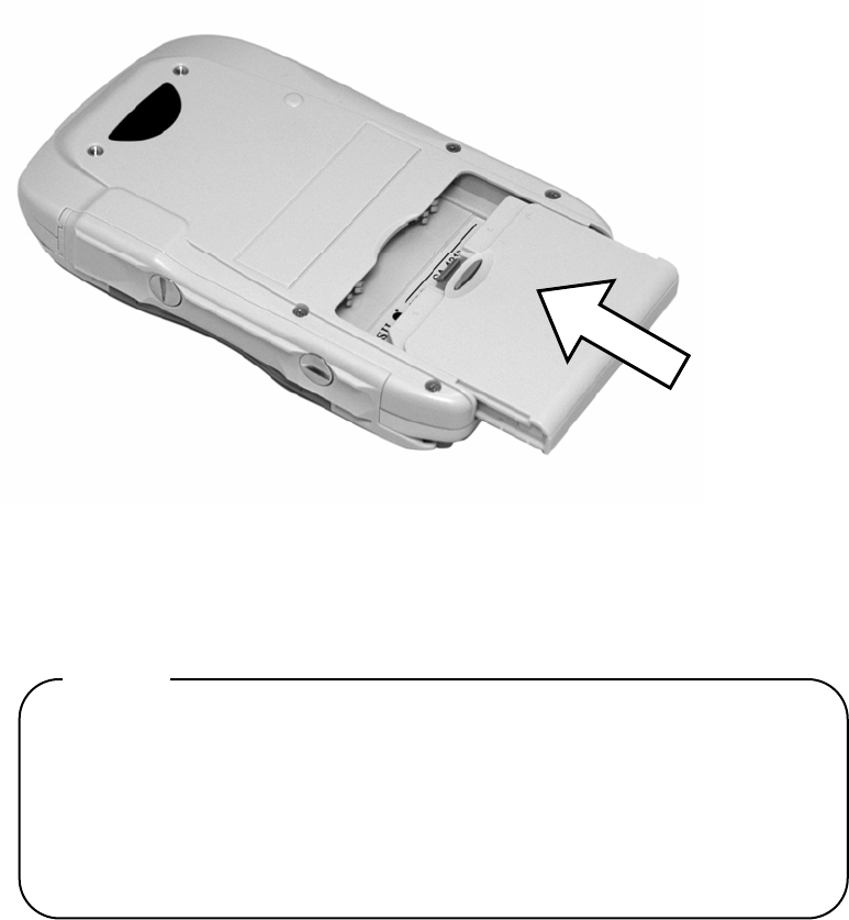
3.3 Mounting and Removing a Battery Pack
3.3.1 Mounting a battery pack
Insert the battery pack into the battery pack mount on the back of the device. Align the
rails in the direction of the arrows and push in until it clicks.
Fig. 3-1: Mounting the battery pack
Caution
Since the backup battery is not charged before shipping, the following
phenomena may occur when mounting it for the first time. See “3.4: Reset” and
reset the device.
- Meaningless characters or images are displayed onscreen.
- Nothing appears onscreen.
- Key entries are disabled.
- A buzzer sounds.
Chapter 3: Power Supply
3-5
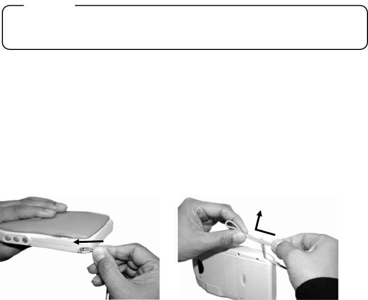
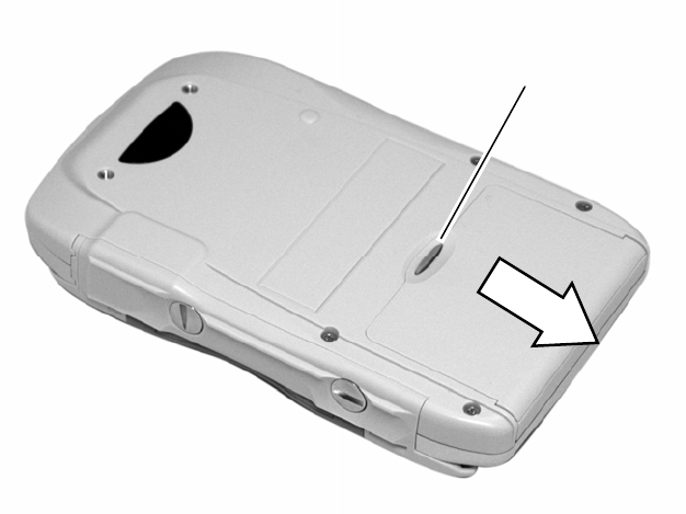
3.3.2 Removing a battery pack
Press and hold the battery pack eject button on the side of the device. Remove the
battery pack in the direction as shown.
Fig. 3-2: Removing the battery pack
Battery pack eject button
3-6
3.4 Reset
Caution
Resetting will delete all the programs (application programs, and others) except
for the data, OS, and terminal settings mode program stored in the device.
Reset the device in the following cases:
- When mounting the battery pack for the first time
- When receiving applications from the Wireless Station
- When the program has not been operating normally
Reset the device as described below.
Press the Scroll UP key and the Enter key at the same time for about 5 seconds.
Fig. 3-3: Reset operation
Enter key
Scroll UP key

4-1
Chapter 4 Terminal Settings Mode Functions
4.1 Functions Overview
The following settings are available on the device.
Version
Displays the version information for the OS, firmware, and library.
Parameter
Sets the OS parameters.
WLAN test
Tests communications between the handheld terminal and the Wireless
Station or the Wireless Repeater.
Touchscreen Calibration
Adjusts the touchscreen coordinates.
Reboot
Restarts the OS.
4-2
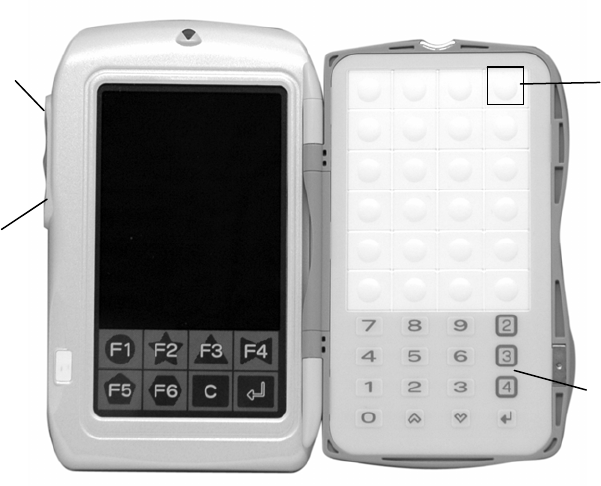
4.2 Startup
Start the terminal settings mode as described below.
(1) Press and hold the Scroll UP key and the Enter key at the same time for about 5
seconds to reset the device.
(2) When the red LED turns on, immediately press and hold the “Right UP key” on
the sheet key for about 3 seconds.
(3) When the screen shown in Fig. 4-2 is displayed, the terminal settings mode has
properly started.
Fig. 4-1: Terminal settings mode startup
Sheet keys
Right UP key
Scroll UP ke
y
Enter ke
y
Chapter 4: Terminal Settings Mode Functions
4-3
4.3 Functions Specifications
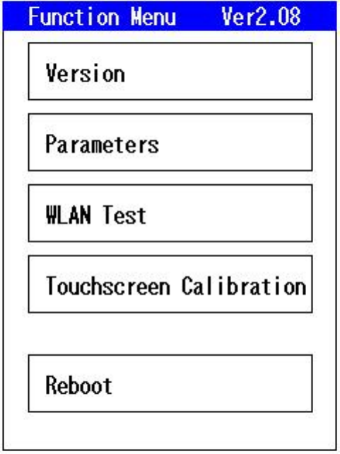
4.3.1 Function Menu
Press menu keys for terminal settings.
Fig. 4-2: Function Menu
[Version] displays the version screen.
[Parameters] displays the parameters screen.
[WLAN Test] displays the WLAN test screen.
[Touchscreen Calibration] displays the touchscreen calibration screen.
[Reboot] restarts the OS.
4-4
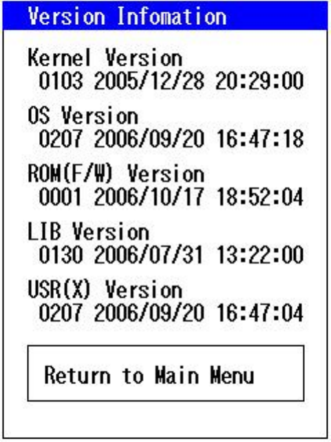
4.3.2 Version
This function displays the versions of the OS, firmware, and library in the terminal.
Select [Version] on the function menu.
Fig. 4-3: Version
Chapter 4: Terminal Settings Mode Functions
4-5
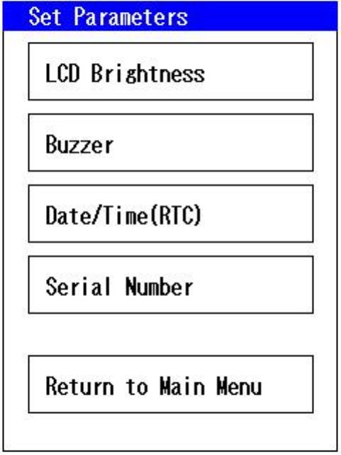
4.3.3 Parameters
This function sets the parameters.
Select [Parameters] on the function menu.
Fig. 4-4: Parameters
4-6
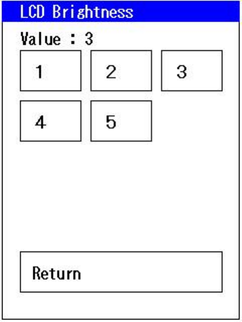
(1) LCD Brightness
Use this function to set the LCD brightness. The set values are stored and saved,
even if the device is reset.
Select [Parameters] – [LCD Brightness] from the function menu.
Select and press number from [1] to [5] onscreen to set the brightness. [5] is the
brightest. The setting is preconfigured to [3].
Fig. 4-5: LCD brightness
Chapter 4: Terminal Settings Mode Functions
4-7
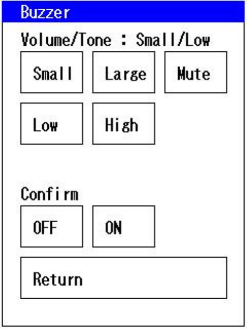
(2) Buzzer
Use this function to set the buzzer. The set values are saved, even if the device is
reset.
Select [Parameters] – [Buzzer] from the function menu.
Select and touch the screen to change the settings. The settings are preconfigured to
“Small and Low”.
Fig. 4-6: Buzzer
4-8
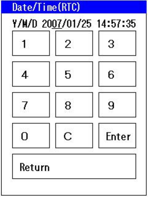
(3) Date/time
Use this function to set date and time. The set date and time are saved, even if the
device is reset, when the battery voltage is within operating parameters.
Select [Parameters] – [Date/time] from the function menu.
The current set value is displayed at the top of the screen. Touch the parameter to be changed. The
selected parameters are underlined. Press the numeric keypad onscreen to change the value. Always enter
two digits; for example, enter “01” for January. Press [Enter]. The message "Settings completed” appears,
and the settings are saved.
Fig. 4-7: Date/time
Chapter 4: Terminal Settings Mode Functions
4-9
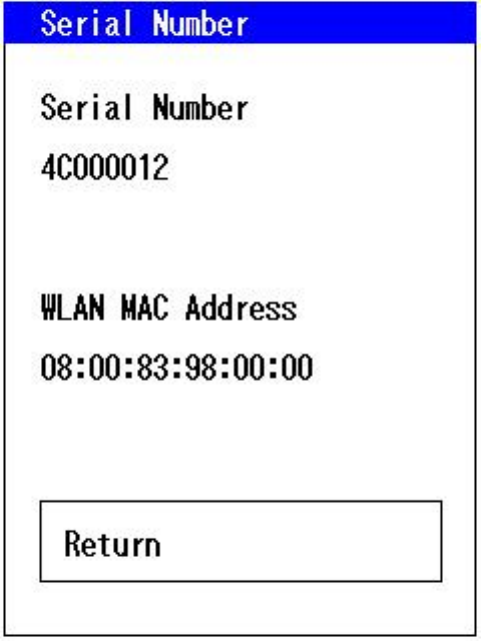
(4) Serial Number
Use this function to refer to the product serial number and the wireless module MAC
address.
Select [Parameters] – [Serial No.] from the function menu.
Fig. 4-8: Serial No.
4-10
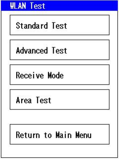
4.3.4 WLAN test
○ Standard test
This function tests the communications between the device, the Wireless Station, and
the Wireless Repeater. Test the communication environment of the anticipated
installation sites if the wireless area measurement does not assure it as an optimum
site.
When performing the standard test before installing in the store, place the Wireless
Station (or Wireless Repeater) at the expected installation site, and set to test mode.
Refer to each device’s manual for how to set to test mode. Use normal mode if the
operation has already started in the store.
Select [WLAN Test] – [Standard Test] from the function menu.
○ Advanced test
This function tests the communications between the device, the Wireless Station, and
the Wireless Repeater.
When performing the standard test before installing in the store, place the devices at
the expected installation sites, and set to test mode. Refer to each device’s manual
for how to set to test mode. Use normal mode if the operation has already started in
the store.
Select [WLAN Test] – [Advanced Test] from the function menu.
○ Receive mode
This mode sets the receiver.
○ Area test
This function lists signal levels between the device and all the stations (repeaters)
available for the device. The signal level data is refreshed every 8 seconds. Set the
same system ID as the station when performing this test.
Chapter 4: Terminal Settings Mode Functions
4-11
Follow the standard test instruction below. The advanced test has additional screens
to set the sender.
Fig. 4-9: WLAN test
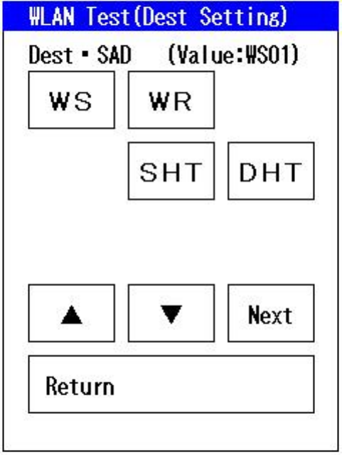
4-12
Specify the destination. Select Wireless Station (WS) or Wireless Repeater (WR). If
several communications destinations have been installed, change the station address
using [▲] and [▼].
Fig. 4-10: WLAN test (Specifying destination)
Chapter 4: Terminal Settings Mode Functions
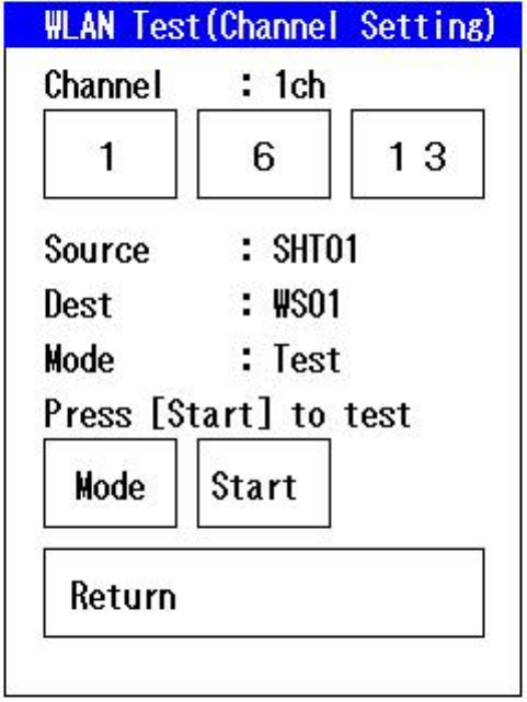
4-13
Specify the communications channel from 1, 6 or 13. Confirm the settings, and touch
[Start].
Communications may be performed via the channel set in the partner device, not via
the channel set in this device.
[Mode]: There are two modes, test mode and normal mode. Use the test mode if the
station is set to test mode. When performing the test after installing the
devices at the store, use the normal mode and set the same system ID as the
station.
Note that some countries and regions cannot use channel 13 due to Radio Law
regulations.
Fig. 4-11: WLAN test (Specifying channel)
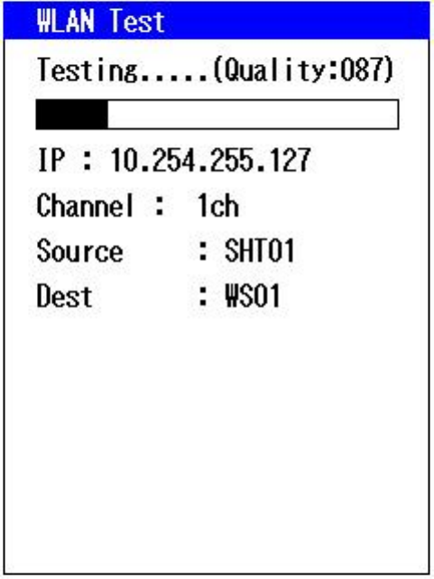
4-14
During the test, the color of the progress bar changes according to the status.
Fig. 4-12: WLAN test (Testing)
Chapter 4: Terminal Settings Mode Functions
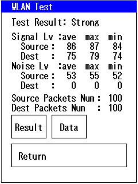
4-15
Press [Result] after the test to display the result. The higher the value of each signal,
the better the communications environment.
The noise level value of the station is displayed as “0” because only the Handheld
Terminals can measure noise level.
[Strong]: Communications are performed in the best conditions.
[Good] : Communications can be performed.
[Poor] : Communications cannot be performed.
Note that the test result is an approximate indication. Environmental changes may
cause communications malfunctions even if the installation sites have not changed.
Fig. 4-13: WLAN test (Results screen 1)
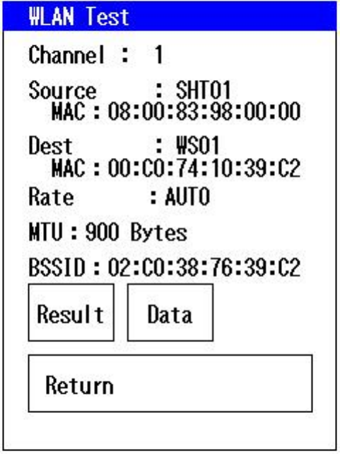
4-16
Test data shows the test environment and parameters.
Fig. 4-14: WLAN test (Results screen 2)
Chapter 4: Terminal Settings Mode Functions
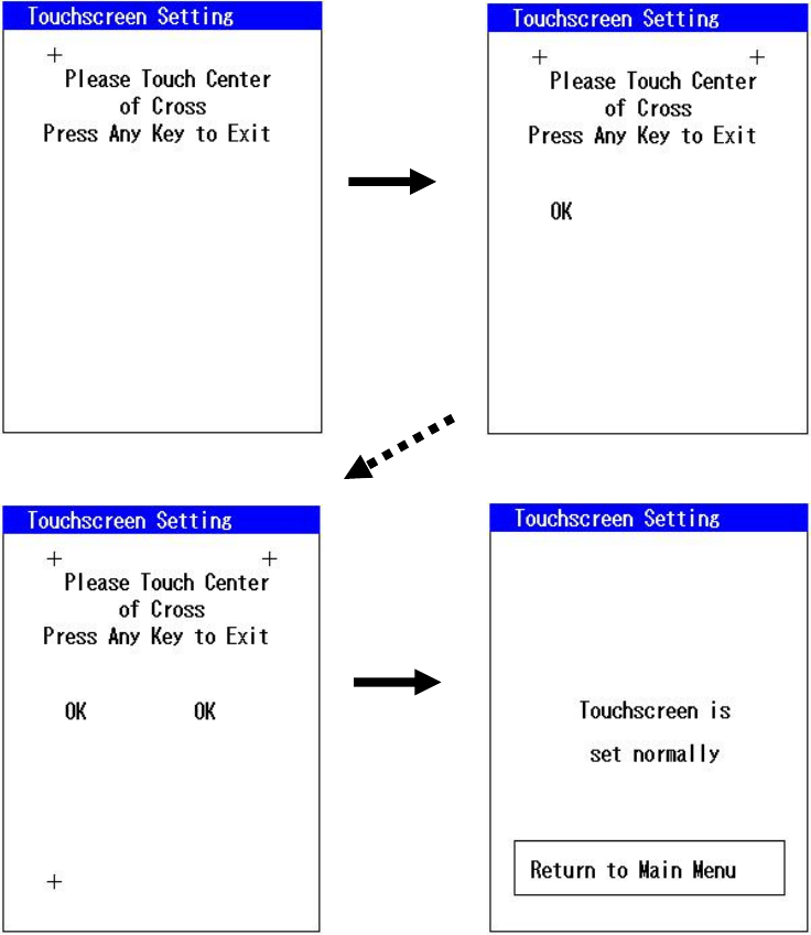
4-17
4.3.5 Touchscreen Calibration
Use this function to adjust the touchscreen calibration.
Touch the crosses according to the messages. The following displays will appear: top
left OK, top right OK, bottom left OK, and bottom right OK. [Return to Main Menu]
appears when the screen is adjusted properly.
If the crosses cannot be touched accurately, the touchscreen calibration can be
canceled by pressing any side key or sheet key. In this case, the settings will not be
saved.
Fig. 4-15: Touchscreen Calibration
Touch the
cross in the
top left
The screen
changes
automatically
Touch the crosses according to the
message

5-1
Chapter 5
Transferring and Starting Application Programs
To use the device, an application program needs to be started. Transfer application
programs from the Wireless Station to the device in the following cases:
- When using the device for the first time since unpacking
- When an application program has been accidentally deleted
- When changing an application program
The procedure for transferring application programs is described below.
5-2
5.1 Downloading Application Programs
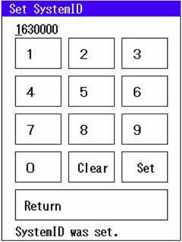
5.1.1 System ID settings
When the Handheld Terminal is properly turned on, the system ID prompt appears.
The system ID is the same 7-digit number used for the Wireless Station.
Enter the 7-digit system ID and press the "Set" button to save. After saving, press the
"Return" button to reboot the device.
Fig. 5-1: System ID settings
Chapter 5: Transferring and Starting Application Programs
5-3
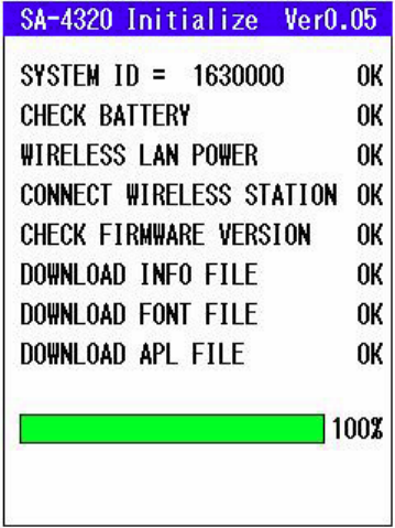
5.1.2 Transferring application programs
The following steps are taken while transferring the application programs:
(1) Checking the system ID
(2) Checking the battery charge
(3) Turning on the wireless LAN network and checking the link
(4) Checking the firmware version of the Handheld Terminal
(5) Downloading the setting files, font files, and application files
If no error occurs, 'OK' will be displayed after each checkpoint as shown in the figure
below and the application programs will start.
Fig. 5-2: Transferring application programs
5-4
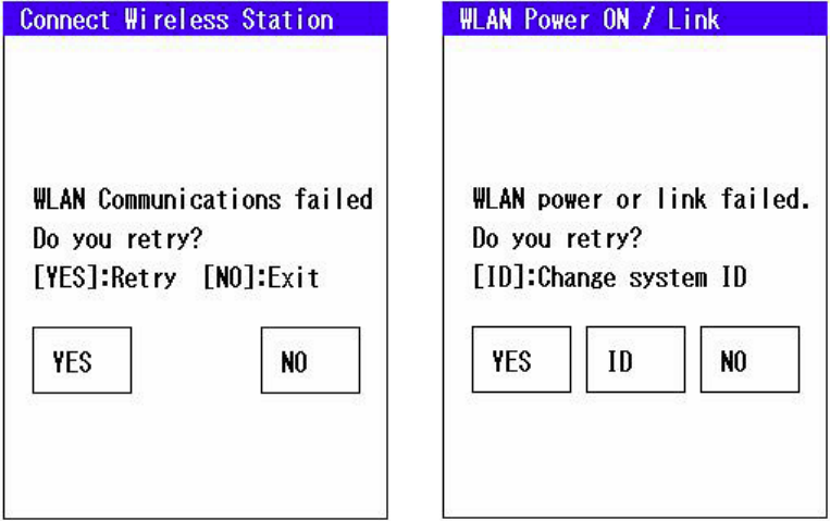
5.1.3 Wireless communications error
Transferring the application programs from the Wireless Station requires being within
its communication range. If communications with the Wireless Station cannot be
established, the following screen shown on the left will be displayed.
If the wireless LAN reports a Link error shown on the right, the system ID may have
been incorrectly input. Press the "ID" button to jump back to the screen for the setting
the system ID.
Fig. 5-3: Trouble communicating with the Wireless Station
Chapter 5: Transferring and Starting Application Programs
5-5
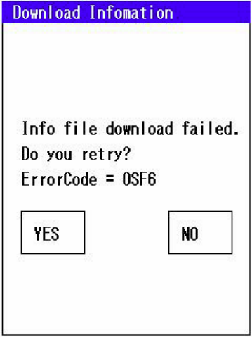
5.1.4 File transfer error
The settings, font files, and application files are transferred from the Wireless Station.
Thus, this must be performed in the range where communications with the Wireless
Station can be established. If communications with the Wireless Station cannot be
established, or if the files within the Wireless Station are missing or corrupt, the
following screen will be displayed:
Fig. 5-4: File transfer error
5-6
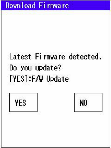
5.1.5 Firmware version upgrade
The Handheld Terminal's firmware upgrades are transferred from the Wireless Station.
This requires the units being within communication range of each other.
When the new firmware is ready in the Wireless Station, the screen shown below is
displayed. Press the "YES" button to start the version upgrade process. Press the
"NO" button to skip the version upgrade process and return to the current task.
When the version upgrade is in progress, the ROM is overwritten, so take care not to
remove the batteries during the upgrade.
After the firmware has been upgraded, the device must be rebooted for the upgrade
to become effective.
Fig. 5-5: Firmware version upgrade
Chapter 5: Transferring and Starting Application Programs
5-7
5.2 Starting Application Programs
See the application program operation manual for how to start an application
program.

6-1
Chapter 6 Troubleshooting
This chapter explains the causes of device problems and their solutions. Determine
whether or not the problem is a malfunction of the device based on these
troubleshooting tips.
6.1 Wireless transfer failure
If wireless transfer fails, apply solutions according to the following conditions.
- Several Handheld Terminals are malfunctioning (See 6.1.1)
- The Handheld Terminals cannot communicate depending on location or method of
use (See 6.1.2)
- A specific handheld terminal cannot communicate (See 6.1.3)

6-2
6.1.1 Transfer failure caused by the system (or device) , or several Handheld Terminals are
malfunctioning
Problem Probable Cause Solution
None of the Handheld
Terminals can communicate.
- Wireless Station is
malfunctioning
- Turn on the power supply to the
Wireless Station again.
The malfunctioning
Handheld Terminals cannot
be specified.
Communication failures due
to other radio waves
- External noise
- A device with the same
frequency is being used
nearby.
- Remove the source of the
external radio waves, for
example try stopping nearby
microwave ovens.
There are locations where
wireless communications are
disabled.
The Wireless Stations are
not installed at appropriate
sites.
- Search for an available
communication area. Select
[Function Menu] – [WLAN Test].
- Move the Wireless Station to a
suitable site.
- A specific Handheld
Terminal is
malfunctioning.
- Multiple Handheld
Terminals are likely to be
malfunctioning
simultaneously.
Frequency drifts or other
abnormalities on the
Wireless Station
(1) Specify the combination of
Wireless Station and Handheld
Terminals that cannot
communicate. Select [Function
Menu] – [WLAN Test].
(2)
If malfunctioning Handheld
Terminals can communicate with
other Wireless Stations, the
Wireless Station is malfunctioning.
The device is malfunctioning if wireless transfer is still disabled after trying the above
solutions.
Return the device to your local service center.

Chapter 6: Troubleshooting
6-3
6.1.2 Communication failure caused by the use of a Handheld Terminal, or malfunction frequently
occurs with a single Handheld Terminal
Problem Probable Cause Solution
- The Wireless Station is
too far from the
Handheld Terminal.
- The Wireless Station is
not in sight.
- The device is used in an
area with electromagnetic
wave interference.
- The signal does not
reach.
Move to a closer location where
the Wireless Station is visible.
- Occurs in a specific
Handheld Terminal when
used in conjunction with
the maintenance
Handheld Terminal.
System IDs are incorrect. (1) Set the system ID according
to the application program
operation manual.
The device is malfunctioning if wireless transfer is still disabled after trying the above
solutions.
Return the device to your local service center.
6.1.3 Communication failure caused by the Handheld Terminal
Problem Probable Cause Solution
- A specific Handheld
Terminal cannot
communicate.
- The Handheld Terminal
is malfunctioning
- Operations temporarily
malfunctioned due to a
shock, such as being
dropped.
- Operations temporarily
malfunctioned due to a
drop in battery voltage.
(1) Replace with a charged battery
pack if the LED is flashing
(orange).
(2) Reset the device.
(3) Check whether the Handheld
Terminal is malfunctioning.
Select [Function Menu] – [WLAN
Test].Change the distance to test
and compare with other
Handheld Terminals.
(4) If the test result is normal, the
operations malfunction was
probably temporary. Download
the application program again.
The device is malfunctioning if wireless transfer is still disabled after trying the above
solutions.
Return the device to your local service center.

6-4
6.2 Nothing appears onscreen, or not properly displayed
Probable Cause Solution
The power supply terminals on either
the battery pack or the main unit are
dirty or broken.
Clean according to “7.1: Daily Maintenance”.
If broken, request repairs.
The battery pack contacts are defective
due to a shock, such as being dropped.
Remove the battery pack, wait several
seconds and remount to the main unit.
Battery power has run out Replace with a charged battery pack.
Runaway due to defective memory
backup
Reset the device and download the
application program again.
Program runaways
See “6.10: Program runaway” for the
causes of runaway.
Reset the device and download the
application program again.
The device is malfunctioning if the screen display is still malfunctioning after trying the
above solutions.
Return the device to your local service center.

Chapter 6: Troubleshooting
6-5
6.3 The keypad tone does not sound, or the sound is too loud or too quiet
Probable Cause Solution
The set volume for the keypad tone is
inappropriate.
・ Set the volume again.
・ If the volume is still inappropriate after
resetting, adjust the volume: select
[Function Menu] – [Parameters] –
[Buzzer].
The device is malfunctioning if the volume still cannot be adjusted after trying the
above solutions.
Return the device to your local service center.
6.4 The system does not respond to key entries
Probable Cause Solution
Program runaways
Keys are malfunctioning
(1) Reset the device.
(2) Assess if the device is malfunctioning.
See “6.10: Program runaway”.
(3) Download the application program.
Sheet key unit service life If the above procedures do not solve the
problem, the malfunction may be due to the
sheet key service life. Purchase and replace
with a new sheet key unit.
The device is malfunctioning if the system still does not respond after trying the above
solutions.
Return the device to your local service center.

6-6
6.5 Not properly operating
Probable Cause Solution
Program runaways
(1) Reset the device.
(2) Download the application program.
(3) Assess if the device is malfunctioning.
See “6.10: Program runaway”.
Multiple menu keys are pressed Do not press two or more menu keys
including side keys simultaneously.
The device is malfunctioning if the device still does not operate properly after trying
the above solutions.
Return the device to your local service center.
6.6 Operating time is too short
Probable Cause Solution
Battery pack service life (rechargeable
approximately 500 times)
Purchase and replace with a new battery
pack.
The charger is malfunctioning if the
operating time of the Handheld Terminals
is too short, even with a new battery
pack.
Return the charger to your local service
center.
The device is malfunctioning if the operating time is abnormally short even with a new
battery pack.
Return the device to your local service center.

Chapter 6: Troubleshooting
6-7
6.7 The application programs are deleted when the battery pack is replaced
Probable Cause Solution
The built-in backup battery has not
been thoroughly charged.
The backup battery has not been charged
before shipping. Mount a charged battery
pack for 24 hours minimum when using the
device for the first time. The Handheld
Terminal can take orders during this time.
To fully charge the backup battery, mounting
the battery pack for a further 1 or 2 days is
necessary.
Backup battery service life
(approximately 3 years at use
temperature of 35°C, and approximately
5 years at use temperature of 20°C)
Replace the backup battery.
Note: If the device is not used for a long time, the backup battery will be fully drained.
The device is malfunctioning if the application programs are still deleted when the
battery pack is replaced after trying the above solutions.
Return the device to your local service center.
6.8 The backlight does not turn on
Probable Cause Solution
The backlight has not been set.
The backlight may not turn on depending on
the application program. If settings can be
edited, change the settings again according
to the application program.
The device is malfunctioning if the backlight still does not turn on after trying the
above solution.
Return the device to your local service center.

6-8
6.9 Program runaway
Probable Cause Explanation Solution
Used in or left out of the
rated temperature range
(in particular 5°C or less)
The data may not be
saved, depending on the
memory characteristics.
This is not a malfunction. Reset
the device and download the
application program.
There is a powerful
external electromagnetic
field
- Program runaway during
operations.
- No reproducibility.
This is not a malfunction. Reset
the device and download the
application program.
Memory software error - Mainly due to radiation
from the memory
package.
- No reproducibility.
This is not a malfunction. Reset
the device and download the
application program.
The Handheld Terminal is
malfunctioning
- Operations are not
possible immediately
after resetting.
- Program runaways due
to shock.
Return the device to your local
service center.
The device is malfunctioning if still has runaway programs after trying the above
solutions.
Return the device to your local service center.
6.10 LED is flashing (Orange)
Condition Probable Cause Solution
The LED is flashing
(orange) even when a
battery pack has been
mounted.
Battery pack voltage is
low.
Replace with a charged battery
pack.
The device is malfunctioning if the LED still flashes orange after trying the above
solutions.
Return the device to your local service center.

7-1
Chapter 7 Maintenance
This chapter explains the maintenance methods to use the device in optimum
conditions. Consult your local service center if you have any further questions.
7.1 Daily maintenance
- Do not use a volatile solvent. If the device is dirty, slightly wet a soft cloth with a
neutral cleaning agent, wring out the cloth thoroughly, and gently wipe the device.
- Wiping with liquid dripping from the cloth may result in a malfunction due to the
liquid seeping in the case, between gaps of the side keys or touchscreen, or into
the sheet keys.
- Prevent the device from getting dirty. Contact will be defective and the device may
not operate properly if the device power supply terminals or battery pack terminals
are dirty. Wipe gently using cotton buds if the terminals are dirty.
- Make sure to prevent dirt. Leaving dirt on the battery pack rails until the dirt
hardens may make it impossible to remove the battery pack.
Caution
Never touch the terminals except for cleaning. This may result in defective
contacts.
Never raise or push down on the terminals.
7-2
Fig. 7-1: Device rails
Fig. 7-2: Battery pack rails
Rails
Rails

Chapter 7: Maintenance
7-3
7.2 Regular maintenance
7.2.1 Replacing a battery pack
(1) Battery pack replacement period
The device uses a rechargeable battery pack. A battery pack life depends on the
conditions of use, but is about one day if 100 orders are entered per day. When the
battery power is exhausted, the LED on the device flashes orange. Replace with a
charged battery immediately since further wireless communications are not available.
See 3.3 for how to mount/remove a battery pack.
Caution
Always prepare a fully-charged battery pack in advance for replacement.
A battery pack takes about 4 hours to charge.
(2) Limits to battery pack replacement time
Handheld Terminals have a built-in backup battery (a rechargeable battery for
backup). Even if the battery pack is removed, the application programs and data will
be saved for 10 minutes. Replace the battery pack within 10 minutes.
Caution
- Leave the battery pack mounted to the Handheld Terminal for 24 hours
minimum after first mounting since its backup battery is not charged before
shipping. The device can take orders during this time.
- Never touch the terminals on the Handheld Terminals or battery packs with
bare hands. If the terminals are dirty, contact may become defective.
7-4
7.2.2 Service life of repeatedly charged battery packs
Battery packs can be repeatedly charged with a charger and used, but will need to be
changed more frequently after charging about 500 times. As this is the operating life
of the battery pack itself, replace with a new battery pack.
7.3 Replacing Parts
7.3.1 Replacing the sheet key cover
Step 1: Bend the sheet key cover and remove the clips as shown below. Remove
the sheet key cover.
Step 2: Mount the new sheet key cover. Insert the clips firmly to fix them in their
original position.
Caution
Do not apply excessive force to the clips. This may break or deform the clips.
Clips
Chapter 7: Maintenance
7-5
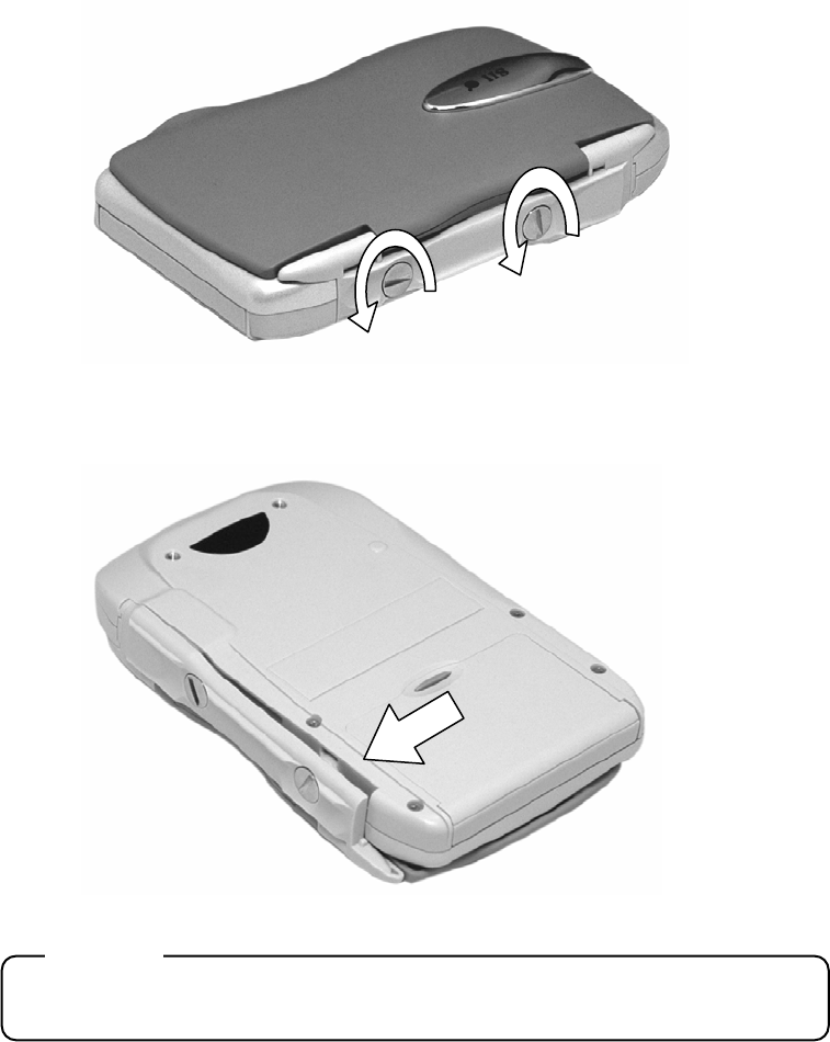
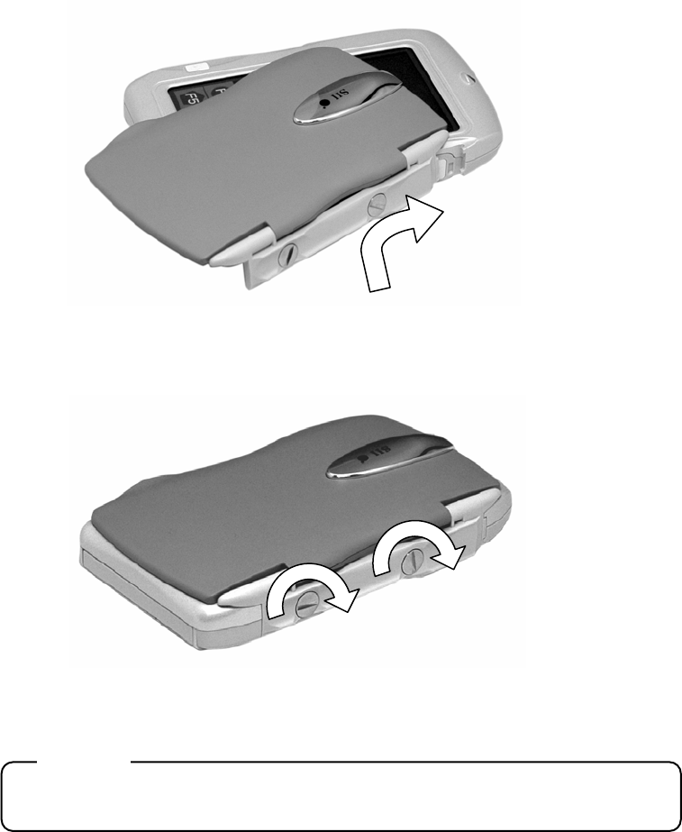
7.3.2 Replacing the sheet key unit
Step 1: Turn the screws at least three times with a coin. (x2 screws)
Step 2: Insert your fingernail into the gap as shown, and remove the panel by
pushing out.
Caution
Do not use hard objects, such as metal or glass, to remove screws.
7-6
Step 3: Align and mount the notches of the new sheet key unit to the clips of the
device.
Step 4: Tighten the screws securely.
Caution
Regularly check that the screws are not loose.
Consult your local service center for replacement of other parts.