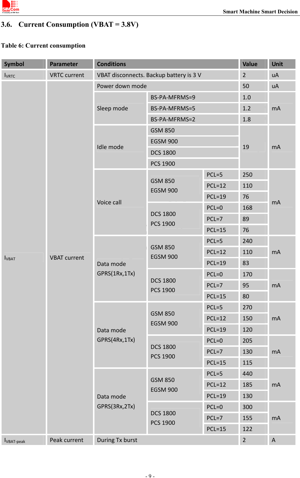
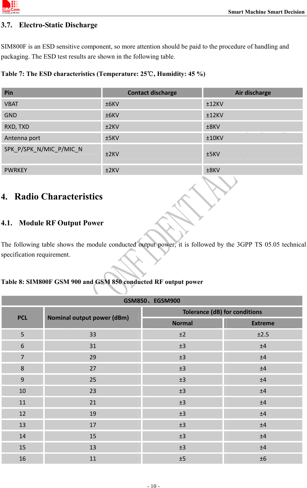
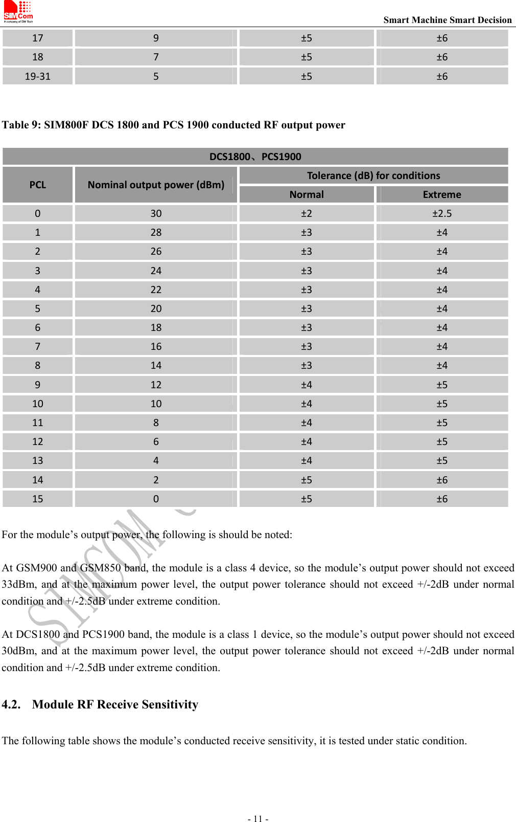
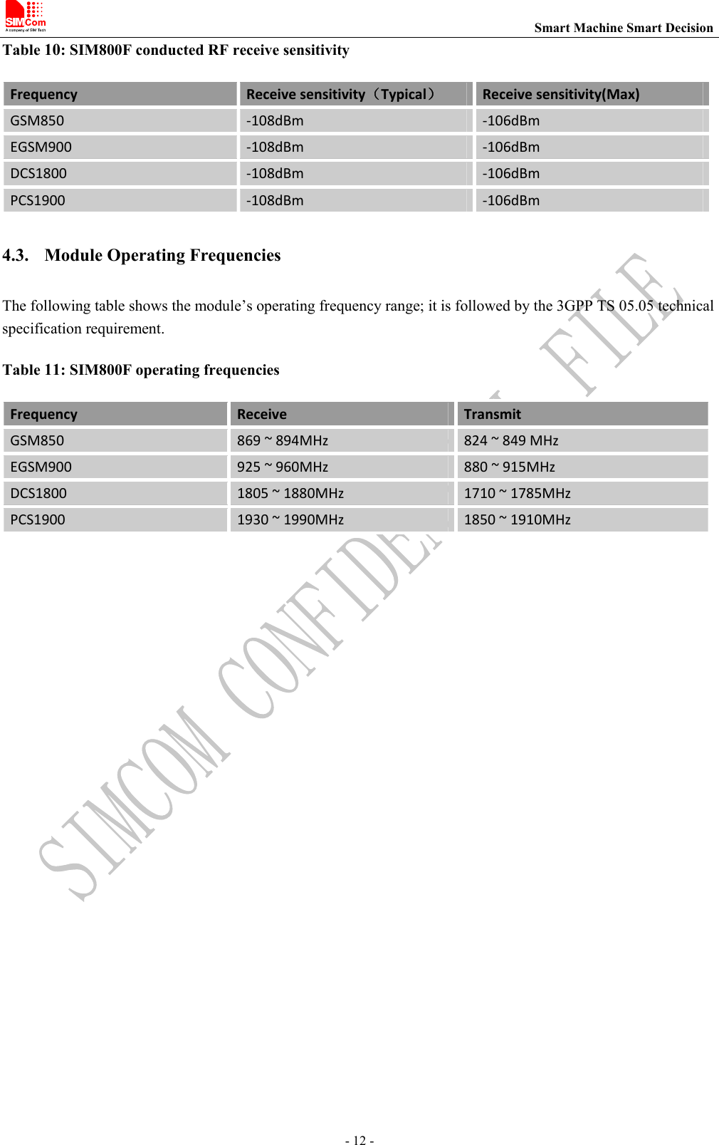
SIMCom Wireless Solutions 8BVA101 GSM/GPRS Wireless Data Module User Manual 6 SIM800F User Manual

Shanghai SIMCom Wireless Solutions Limited GSM/GPRS Wireless Data Module 6 SIM800F User Manual

User Manual

                                                              SIM800F_User Manual_ V1.00
                                                                         Smart Machine Smart Decision - 2 -  Notes This equipment is in compliance with the essential requirements and other relevant provisions of Directive 2014/53/EU.    The device complies with RF specifications when the device used at 20cm form your body.   General Notes SIMCom offers this information as a service to its customers, to support application and engineering efforts that use  the  products  designed  by  SIMCom.  The  information  provided  is  based  upon  requirements  specifically provided  to  SIMCom  by  the  customers.  SIMCom  has  not  undertaken  any  independent  search  for  additional relevant information, including any information that may be in the customer’s possession. Furthermore, system validation of this product designed by SIMCom within a larger electronic system remains the responsibility of the customer or the customer’s system integrator. All specifications supplied herein are subject to change.      WAR NING :    This device complies with part 15 of the FCC Rules. Operation is subject to the following two conditions: (1) This device may not cause harmful interference, and   (2) This  device  must  accept  any  interference  received,  including  interference  that  may  cause  undesired operation.Changes or modifications not expressly approved by the party responsible for compliance could void the user’s authority to operate the equipment.  NOTE: This equipment has been tested and found to comply with the limits for a Class B digital device, pursuant to part  15  of  the  FCC  Rules.    These  limits  are  designed  to  provide  reasonable  protection  against  harmful interference in a residential installation.   This  equipment  generates,  uses  and  can  radiate  radio  frequency  energy  and,  if  not  installed  and  used  in accordance with the instructions, may cause harmful interference to radio communications.    However, there is  no  guarantee  that  interference  will  not  occur  in  a  particular  installation.    If  this  equipment  does  cause harmful interference to radio or television reception, which can be determined by turning the equipment off and on, the user is encouraged to try to correct the interference by one or more of the following measures:     - Reorient or relocate the receiving antenna.   - Increase the separation between the equipment and receiver.     -Connect the equipment into an outlet on a circuit different from that to which the receiver is connected.   -Consult the dealer or an experienced radio/TV technician for help.  RF Exposure Statement:  FCC Caution   (1) Exposure to Radio Frequency Radiation. This equipment must be installed and operated in accordance with
                                                                         Smart Machine Smart Decision - 3 - provided  instructions  and  the  antenna(s)  used  for  this  transmitter must be installed to provide a separation distance of at least 20 cm from all persons and must not be collocated or operating in conjunction with any other antenna or  transmitter. End-users and installers must be provided with antenna installation instructions and transmitter operating conditions for satisfying RF exposure compliance.     (2) Any changes or modifications not expressly approved by the grantee of this device could void the user's authority to operate the equipment.     (3) This Transmitter must not be co-located or operating in conjunction with any other antenna or transmitter.   (4) Changes or modifications to this unit not expressly approved by the party responsible for compliance could void the user authority to operate the equipment.   (5) The modules FCC ID is not visible when installed in the host, or   (6) If the host is marketed so that end users do not have straight forward commonly used methods for access to remove the module so that the FCC ID of the module is visible; then an additional permanent label referring to the  enclosed  module:  Contains  Transmitter  Module  FCC  ID:  2AJYU-8BVA101  or  Contains  FCC  ID: 2AJYU-8BVA101 must be used.  Copyright This document contains proprietary technical information which is the property of Shanghai SIMCom Wireless Solutions Ltd, copying of this document and giving it to others and the using or communication of the contents thereof,  are  forbidden  without  express  authority.  Offenders  are  liable  to  the  payment  of  damages.  All  rights reserved  in  the  event  of  grant  of  a  patent  or  the  registration  of  a  utility  model  or  design.  All  specification supplied herein are subject to change without notice at any time.    Copyright © Shanghai SIMCom Wireless Solutions Ltd. 2015.
                                                                         Smart Machine Smart Decision - 4 -  1. SIM800F Description 1.1. Summarize SIM800F designed by SIMCom is  a  quad band module which supports GSM/GPRS. The  baseband  circuit  is based on MTK and RF circuit is based on RFMD. It works at quad bands------GSM850, EGSM900, DCS1800, and PCS1900. CPU clock is based on 26MHz crystal. The main IC includes MT6261 and RF7198. 1.2. Feature ●  Quad-Band 850/900/1800/1900MHz ●  GPRS multi-slot class 12/10 ●  GPRS mobile station class B ●  Compliant to GSM phase 2/2+ – Class 4 (2 W @ 850/900 MHz) – Class 1 (1 W @ 1800/1900MHz) ●  Dimensions: 24*24*3 mm ●  Weight: 3.1 g ●  Control via AT commands (3GPP TS 27.007, 27.005 and SIMCom enhanced AT Commands) ●  Supply voltage range 3.6~4.2 V ●  Low power consumption ●  Operation temperature:-30~80℃ ●  68 SMT pads include – Interface to external SIM 3V/1.8V – Analog audio interface – RTC backup – Serial interface – USB interface – Keypad interface – LCD interface – Antenna pad – PCM – GPIO – ADC
                                                                         Smart Machine Smart Decision - 5 - 1.3. Pin  Figure 1: SIM800F pin out diagram (Top view)
                                                                         Smart Machine Smart Decision - 6 - 1.4. Dimension  Figure 2: Dimention
                                                                         Smart Machine Smart Decision - 7 - 2. Detail Block Diagram AnalogbasebandDigitalbasebandPower management unitRadio FrequencyPower SupplyAnalog Interface Digital InterfaceRTC AudioADCGSMKeypad/GPIOUARTSIMUSBLCD/SPII2CPWM Figure 3: Block diagram of SIM800F  3. Electrical and Reliability Characteristics 3.1. Absolute Maximum Ratings The absolute maximum ratings stated in following table are stress ratings under non-operating conditions. Stresses beyond any of these limits will cause permanent damage to SIM800F.  Table 1: Absolute maximum ratings Symbol Parameter Min Typ Max UnitVBAT Powersupplyvoltage ‐ ‐ 4.5 VVBUS ‐ ‐ 30 V VBUSII*Inputcurrent ‐ ‐ 8 mAIO*Outputcurrent ‐ ‐ 8 mA*These parameters are for digital interface pins, such as keypad, GPIO, I2C, UART, LCD and DEBUG. 3.2. Digital Interface Characteristics Table 2: Digital interface characteristicsSymbol Parameter Min Typ Max UnitIIHHigh‐levelinputcurrent 2.1 ‐ 3.1 VIILLow‐levelinputcurrent ‐0.3 ‐ 0.7 V
                                                                         Smart Machine Smart Decision - 8 - VOHHigh‐levelinputvoltage 2.4 ‐ ‐ VVOLLow‐levelinputvoltage ‐ ‐ 0.4 V* These parameters are for digital interface pins, such as keypad, GPIO, I2C, UART, LCD, PWMs and DEBUG.  3.3. SIM Card Interface Characteristics Table 3: SIM card interface characteristicsSymbol Parameter Min Typ Max UnitIIHHigh‐levelinputcurrent ‐1 ‐ 1 uAIILLow‐levelinputcurrent ‐1 ‐ 1 uAVIHHigh‐levelinputvoltage 1.4 ‐ ‐ V2.4 ‐ ‐ VVILLow‐levelinputvoltage ‐ ‐ 0.27 V0.4 VVOHHigh‐leveloutputvoltage 1.62 ‐ ‐ V2.7 ‐ ‐ VVOLLow‐leveloutputvoltage ‐ ‐ 0.36 V‐ ‐ 0.4 V3.4. SIM_VDD Characteristics Table 4: SIM_VDD characteristicsSymbol Parameter Min Typ Max UnitVOOutputvoltage 2.70 2.80 2.90 VIOOutputcurrent ‐ ‐ 50 mA 3.5. VRTC Characteristics Table 5: VRTC characteristicsSymbol Parameter Min Typ Max UnitVRTC‐INVRTCinputvoltage 2.8 VIRTC‐INVRTCinputcurrent ‐ 3 ‐ uAVRTC‐OUTVRTCoutputvoltage ‐ 2.8 ‐ VIRTC‐OUTVRTCoutputcurrent ‐ 2 mA
                                                                         Smart Machine Smart Decision - 9 - 3.6. Current Consumption (VBAT = 3.8V) Table 6: Current consumptionSymbol Parameter Conditions Value UnitIVRTCVRTCcurrent VBATdisconnects.Backupbatteryis3V 2 uAIVBATVBATcurrentPowerdownmode 50 uASleepmodeBS‐PA‐MFRMS=9 1.0mABS‐PA‐MFRMS=5 1.2BS‐PA‐MFRMS=2 1.8IdlemodeGSM85019 mAEGSM900DCS1800PCS1900VoicecallGSM850EGSM900PCL=5 250mAPCL=12 110PCL=19 76DCS1800PCS1900PCL=0 168PCL=7 89PCL=15 76DatamodeGPRS(1Rx,1Tx)GSM850EGSM900PCL=5 240mAPCL=12 110PCL=19 83DCS1800PCS1900PCL=0 170mAPCL=7 95PCL=15 80DatamodeGPRS(4Rx,1Tx)GSM850EGSM900PCL=5 270mAPCL=12 150PCL=19 120DCS1800PCS1900PCL=0 205mAPCL=7 130PCL=15 115DatamodeGPRS(3Rx,2Tx)GSM850EGSM900PCL=5 440mAPCL=12 185PCL=19 130DCS1800PCS1900PCL=0 300mAPCL=7 155PCL=15 122IVBAT‐peak Peakcurrent  DuringTxburst 2 A
                                                                         Smart Machine Smart Decision - 10 - 3.7. Electro-Static Discharge SIM800F is an ESD sensitive component, so more attention should be paid to the procedure of handling and packaging. The ESD test results are shown in the following table. Table 7: The ESD characteristics (Temperature: 25℃, Humidity: 45 %) Pin Contactdischarge AirdischargeVBAT ±6KV ±12KVGND ±6KV ±12KVRXD,TXD ±2KV ±8KVAntennaport ±5KV ±10KVSPK_P/SPK_N/MIC_P/MIC_N ±2KV ±5KVPWRKEY ±2KV ±8KV 4. Radio Characteristics 4.1. Module RF Output Power The following table shows the module conducted output power, it is followed by the  3GPP TS 05.05 technical specification requirement.  Table 8: SIM800F GSM 900 and GSM 850 conducted RF output power GSM850、EGSM900PCL Nominaloutputpower(dBm) Tolerance(dB)forconditionsNormal Extreme5 33 ±2 ±2.56 31 ±3 ±47 29 ±3 ±48 27 ±3 ±49 25 ±3 ±410 23 ±3 ±411 21 ±3 ±412 19 ±3 ±413 17 ±3 ±414 15 ±3 ±415 13 ±3 ±416 11 ±5 ±6
                                                                         Smart Machine Smart Decision - 11 - 17 9 ±5 ±618 7 ±5 ±619‐31 5 ±5 ±6 Table 9: SIM800F DCS 1800 and PCS 1900 conducted RF output power DCS1800、PCS1900PCL Nominaloutputpower(dBm) Tolerance(dB)forconditionsNormal Extreme0 30 ±2 ±2.51 28 ±3 ±42 26 ±3 ±43 24 ±3 ±44 22 ±3 ±45 20 ±3 ±46 18 ±3 ±47 16 ±3 ±48 14 ±3 ±49 12 ±4 ±510 10 ±4 ±511 8 ±4 ±512 6 ±4 ±513 4 ±4 ±514 2 ±5 ±615 0 ±5 ±6 For the module’s output power, the following is should be noted:    At GSM900 and GSM850 band, the module is a class 4 device, so the module’s output power should not exceed 33dBm, and at the maximum  power  level, the output power tolerance should not exceed +/-2dB under normal condition and +/-2.5dB under extreme condition.  At DCS1800 and PCS1900 band, the module is a class 1 device, so the module’s output power should not exceed 30dBm, and at the maximum  power  level, the output power tolerance should not exceed +/-2dB under normal condition and +/-2.5dB under extreme condition. 4.2. Module RF Receive Sensitivity The following table shows the module’s conducted receive sensitivity, it is tested under static condition.
                                                                         Smart Machine Smart Decision - 12 - Table 10: SIM800F conducted RF receive sensitivity Frequency  Receivesensitivity(Typical)Receivesensitivity(Max)GSM850 ‐108dBm ‐106dBmEGSM900 ‐108dBm ‐106dBmDCS1800 ‐108dBm ‐106dBmPCS1900 ‐108dBm ‐106dBm4.3. Module Operating Frequencies The following table shows the module’s operating frequency range; it is followed by the 3GPP TS 05.05 technical specification requirement. Table 11: SIM800F operating frequencies Frequency  Receive  Transmit GSM850 869~894MHz 824~849MHzEGSM900 925~960MHz 880~915MHzDCS1800 1805~1880MHz 1710~1785MHzPCS1900 1930~1990MHz 1850~1910MHz
                                                                         Smart Machine Smart Decision - 13 - Contact us: Shanghai SIMCom Wireless Solutions Limited.  Address: Building B, No.633 Jinzhong Road, Changning District, Shanghai P.R.China 200335 Tel: +86 21 3157 5100\3157 5200 Email: simcom@simcom.com, simcom@sim.com Website: www.simcomm2m.com
FCC Statement This device complies with part 15 of the FCC Rules. Operation is subject to the following two conditions:   (1) This device may not cause harmful interference, and   (2) this device must accept any interference received, including interference that may cause undesired operation.  Any Changes or modifications not expressly approved by the party responsible for compliance could void the user's authority to operate the equipment. The modular can be installed or integrated in mobile or fix devices only. This modular cannot be installed in any portable device.  FCC Radiation Exposure Statement This modular complies with FCC RF radiation exposure limits set forth for an uncontrolled environment. This transmitter must not be co-located or operating in conjunction with any other antenna or transmitter. This modular must be installed and operated with a minimum distance of20 cm between the radiator and user body.  If the FCC identification number is not visible when the module is installed inside another device, then the outside of the device into which the module is installed must also display a label referring to the enclosed module. This exterior label can use wording such as the following: “Contains Transmitter Module FCC ID: 2AJYU-8BVA101 Or Contains FCC ID: 2AJYU-8BVA101”  When the module is installed inside another device, the user manual of the host must contain below warning statements; 1. This device complies with Part 15 of the FCC Rules. Operation is subject to the following two conditions: (1) This device may not cause harmful interference. (2) This device must accept any interference received, including interference that may cause undesired operation.  2. Changes or modifications not expressly approved by the party responsible for compliance could void the user's authority to operate the equipment.  The devices must be installed and used in strict accordance with the manufacturer's instructions as described in the user documentation that comes with the product.  Any company of the host device which install this modular with Single modular approval should perform the test of radiated emissionand spurious emission according to FCC part 15C : 15.247 and 15.209 requirement,Only if the test result comply with FCC part 15C : 15.247 and 15.209 requirement,then the host can be sold legally.

Navigation menu