SK Telesys SKSN-C30-CO CDMA RF Repeater User Manual
SK Telesys Co.,Ltd. CDMA RF Repeater
UserManual.wiki
>
SK Telesys
>
SKSN C30 CO User Manual
Users Manual
Navigation menu
Upload a User Manual
Namespaces
Wiki Guide
HTML
PDF
Info
Views
User Manual
Discussion / Help
Navigation
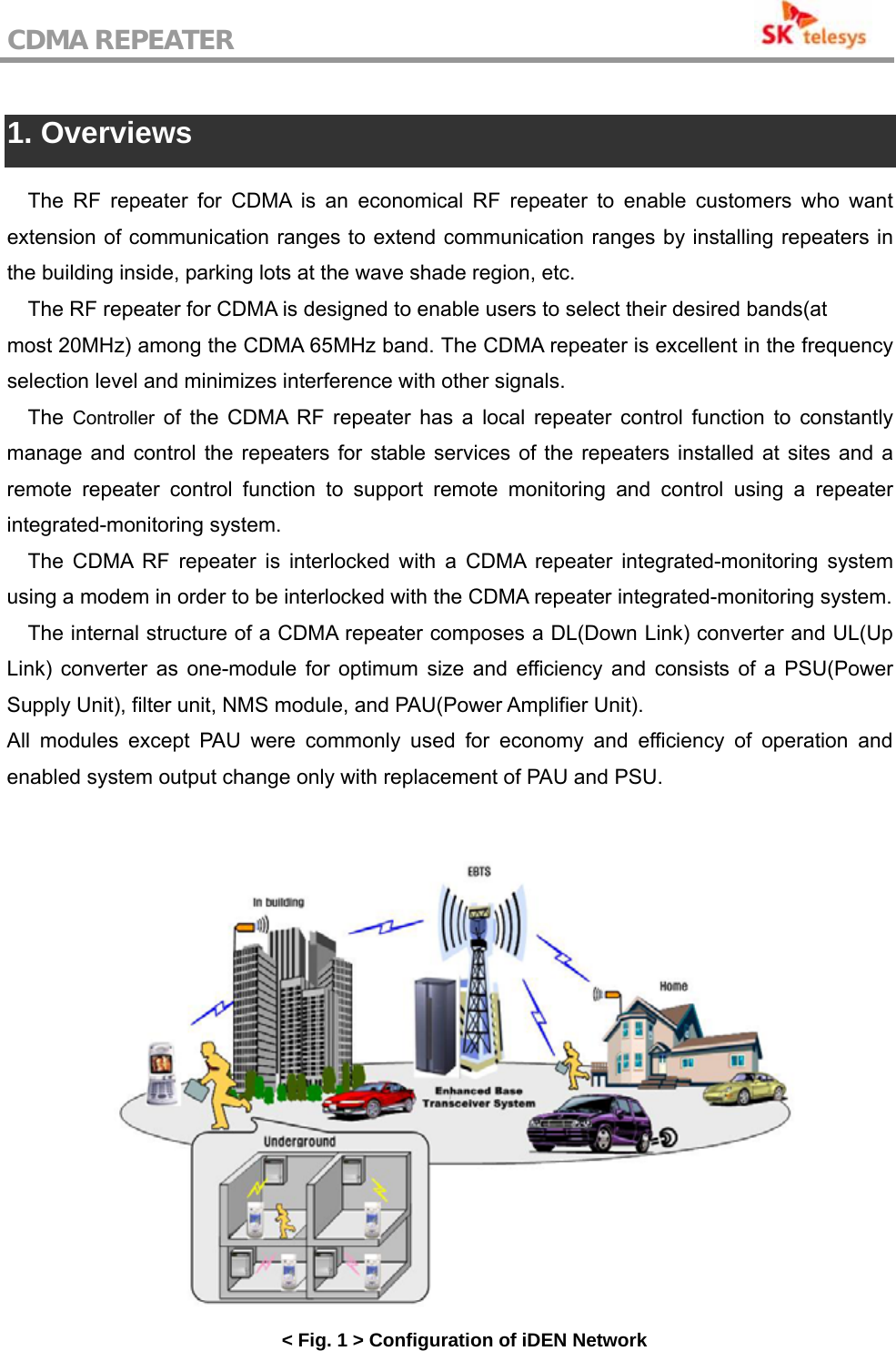
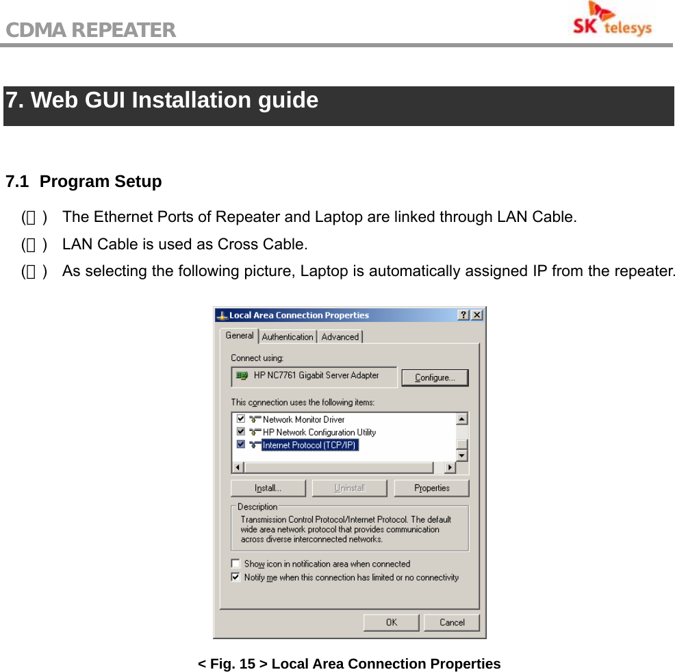
![CDMA REPEATER 7.2 Web GUI Connection (1) Input connection address on address window of Internet Explorer to access. (2) The Connection address set up as the repeater is released is as follows; http://192.168.10.101/ As linked to the repeater, input Username and Password on Login screen as follows to click [Login]. < Fig. 19 > Web GUI Initial Screen (3) Default Username & Password set up as the repeater is released are skts & skts. (4) As linked to Web GUI, the following screen appears.](https://usermanual.wiki/SK-Telesys/SKSN-C30-CO/User-Guide-827239-Page-31.png)
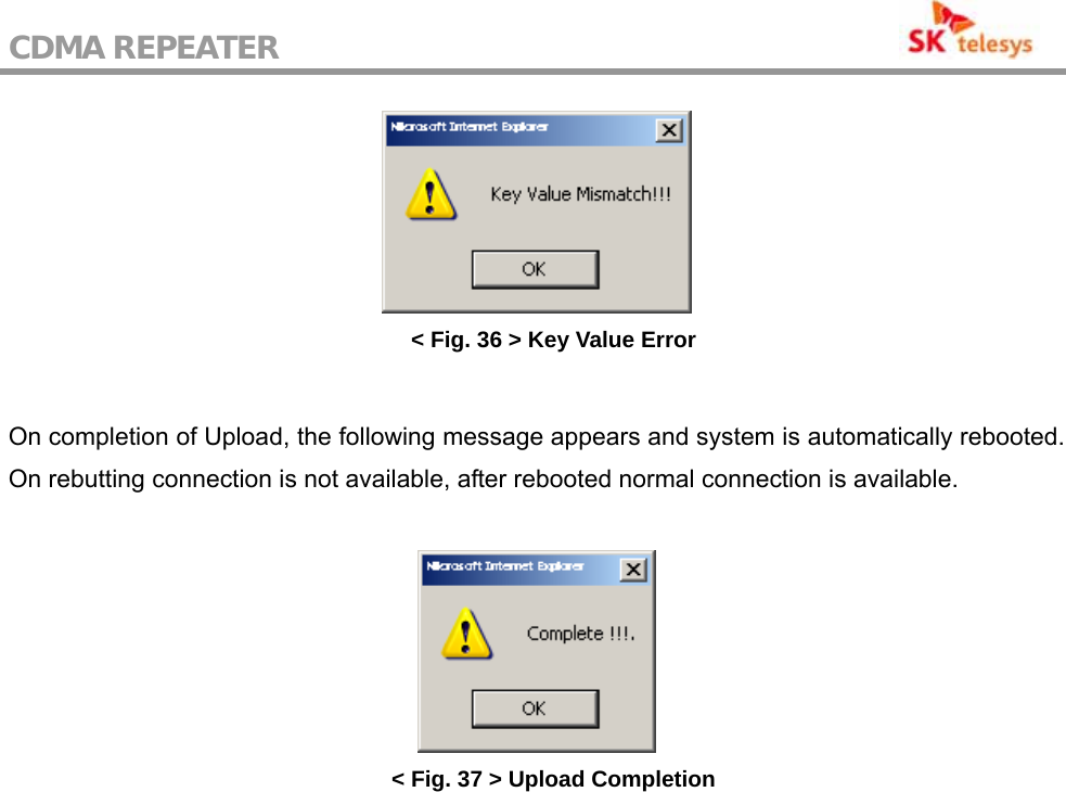
![CDMA REPEATER Click [Search] button to select the file for Uploading on Popup window. Controller of repeater comprises Network Control Board and Repeater Control Board, and each Board’s Upload file is divided into SKTSNCB_vxx.ncu and SKTSRCB_x_vx.x.xx.rcu. < Fig. 34 > File Selection < Fig. 35 > Upload Arrangement As the selected file path is seen, input Key Value provided and press Upload button to Upgrade system. If Key Value is different by files and inaccurate, Upload is impossible.](https://usermanual.wiki/SK-Telesys/SKSN-C30-CO/User-Guide-827239-Page-38.png)