SKF France TPMS-ECU TPMS ECU collects TPMS EWMs data, diagnose it to give tire pressure status to truck driver User Manual Mounting instructions of TPMS
SKF France TPMS ECU collects TPMS EWMs data, diagnose it to give tire pressure status to truck driver Mounting instructions of TPMS
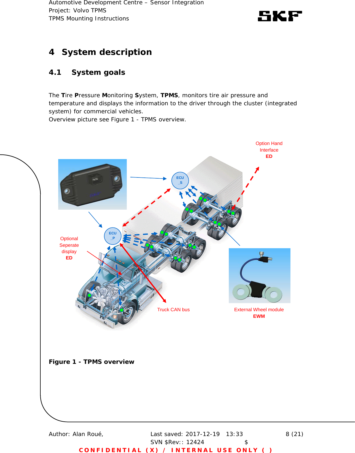
Mounting instructions of TPMS
![Automotive Development Centre – Sensor Integration Project: Volvo TPMS TPMS Mounting Instructions Author: Alan Roué, Last saved: 2017-12-19 13:33 SVN $Rev:: 12424 $ 3 (21) CONFIDENTIAL (X) / INTERNAL USE ONLY ( ) Abbreviations Abbreviations Explanation DID Data identifier ECU Electronic Control Unit (TPM main control unit) ECU_P Primary ECU on truck ECU_Sx Secondary ECU on trailer(s) EWM External Wheel Module (sensor variant mounted between 2 wheel bolts) MM Main module, main part of EWM P Tire pressure RF Radio Frequency (partly used as synonym for radio[-communication]) TPMS Tire Pressure Monitoring System VM Valve module (part of EWM assembled on tire valve) WM Wheel module (sensor on tire)](https://usermanual.wiki/SKF-France/TPMS-ECU/User-Guide-3732256-Page-3.png)