SKF France TPMS-ECU TPMS ECU collects TPMS EWMs data, diagnose it to give tire pressure status to truck driver User Manual Mounting instructions of TPMS
SKF France TPMS ECU collects TPMS EWMs data, diagnose it to give tire pressure status to truck driver Mounting instructions of TPMS
Mounting instructions of TPMS

Automotive Development Centre – Sensor Integration
Project: Volvo TPMS
TPMS Mounting Instructions
Author: Alan Roué,
Last saved: 2017-12-19 13:33
SVN $Rev:: 12424 $ 1 (21)
CONFIDENTIAL (X) / INTERNAL USE ONLY ( )
TPMS Mounting Instructions
For products 21851508 / 21780658 / 21780660 / 21780662 / 21923656
Document status: in work ( ) / under review () / released (X) / obsolete ( )

Automotive Development Centre – Sensor Integration
Project: Volvo TPMS
TPMS Mounting Instructions
Author: Alan Roué,
Last saved: 2017-12-19 13:33
SVN $Rev:: 12424 $ 2 (21)
CONFIDENTIAL (X) / INTERNAL USE ONLY ( )
Table of contents
ABBREVIATIONS .................................................................................. 3
NAMING CONVENTIONS ......................................................................... 4
1REVISION HISTORY .................................................................. 5
2SCOPE ................................................................................... 6
3PRECONDITIONS ...................................................................... 7
4SYSTEM DESCRIPTION ............................................................... 8
4.1System goals ......................................................................... 8
4.2End customer benefits ............................................................. 9
4.3User profiles .......................................................................... 9
4.4System applications ................................................................ 9
4.4.1Driving situation ..................................................................................... 9
4.4.2Configuration by the end customer ......................................................... 10
4.4.3Configuration during truck production ..................................................... 10
4.4.4Single tire change on road ..................................................................... 10
4.4.5Maintenance, service by the workshop .................................................... 10
5TPMS MOUNTING INSTRUCTIONS .............................................. 12
5.1SW download ....................................................................... 12
5.2Mounting the TPM ECU .......................................................... 13
5.3Mounting the WMs ................................................................ 14
5.4Front and tag/pusher axle installation with single mounted wheel 16
5.4.1Counter weight .................................................................................... 16
5.4.2Protecting ring ..................................................................................... 17
5.4.3Light weight pusher axle (WTP-D245) ..................................................... 17
5.5Rear and tag axle double mounted wheel (WTD-DUAL, WTT-DUAL)
18
5.6Calibration of WMs ................................................................ 19
5.6.1Creating the WM id parameter ............................................................... 19
5.6.2Writing WM id parameter and WM calibration ........................................... 19
5.7End of line testing ................................................................ 20
6TPMS EWM BORDELINE RISKS ................................................ 21
6.1Ignition hazard risk analysis ................................................... 21
6.2Borderline risks analysis ........................................................ 21

Automotive Development Centre – Sensor Integration
Project: Volvo TPMS
TPMS Mounting Instructions
Author: Alan Roué,
Last saved: 2017-12-19 13:33
SVN $Rev:: 12424 $ 3 (21)
CONFIDENTIAL (X) / INTERNAL USE ONLY ( )
Abbreviations
Abbreviations Explanation
DID Data identifier
ECU Electronic Control Unit (TPM main control unit)
ECU_P Primary ECU on truck
ECU_Sx Secondary ECU on trailer(s)
EWM External Wheel Module (sensor variant mounted between 2 wheel bolts)
MM Main module, main part of EWM
P Tire pressure
RF Radio Frequency (partly used as synonym for radio[-communication])
TPMS Tire Pressure Monitoring System
VM Valve module (part of EWM assembled on tire valve)
WM Wheel module (sensor on tire)

Automotive Development Centre – Sensor Integration
Project: Volvo TPMS
TPMS Mounting Instructions
Author: Alan Roué,
Last saved: 2017-12-19 13:33
SVN $Rev:: 12424 $ 4 (21)
CONFIDENTIAL (X) / INTERNAL USE ONLY ( )
Naming Conventions
Name Explanation
Wheel Module Positioning Procedure to define the position of a wheel module (WM) on
a truck or trailer.
This defines the tire on which a WM is mounted (belongs to).
Trailer Mating Procedure to make a trailer part of a convoy
Convoy A truck with one or more trailers
Vehicle Unit A single truck or trailer

Automotive Development Centre – Sensor Integration
Project: Volvo TPMS
TPMS Mounting Instructions
Author: Alan Roué,
Last saved: 2017-12-19 13:33
SVN $Rev:: 12424 $ 5 (21)
CONFIDENTIAL (X) / INTERNAL USE ONLY ( )
1 Revision History
Sub-Version Revision: $Rev:: 12424 $
Date Changes (with reference to change request) Author
2015-04-17 First version ready to review Jens Graf /
Alan Roue
2015-04-24 Review performed (some findings direct implemented)
Review Protocol:
Review_Protocol_TPMS_Mounting_Instructions.xls
Jens Graf
2015-04-27 Add remarks of Jens done during the review Alan Roue
2015-08-24 Add product references in Scope paragraph Alan Roue
2015-09-15 Add TPMS not safety system §4.4.6 Alan Roue
2017-12-19 Remove P8 and .P08 in front page and scope
Add 2 parts statement requested by FCC Part 15.19
(a)(3): could not cause harmfull interference & can
accept interferences. §4.4.7
Alan Roue

Automotive Development Centre – Sensor Integration
Project: Volvo TPMS
TPMS Mounting Instructions
Author: Alan Roué,
Last saved: 2017-12-19 13:33
SVN $Rev:: 12424 $ 6 (21)
CONFIDENTIAL (X) / INTERNAL USE ONLY ( )
2 Scope
This Technical Requirements (TR) covers requirements for assembly and calibration
process for the Tire Pressure Monitoring System (TPMS) described in table below. For
parts specifications, refer to PDM-system (example KOLA), Bill-Of-Material (BOM) or
similar.
Customer References SKF Reference SKF Designation
21851508 BH-EP-WPM 01 SKF TPMS Electronic
Control Unit
21780658 BH-LS-WPM 02E SKF TPMS External Wheel
Module 0°
21780660 BH-LS-WPM 01E SKF TPMS External Wheel
Module 90°
21780662 BH-LS-WPM 03E SKF TPMS External Wheel
Module 135°
21923656 BH-VA-WPM 01E SKF TPMS Counterweight
Truck rims covered by this this TPMS mounting instructions are:
Rims of 17.5”
Rims of 22.5”

Automotive Development Centre – Sensor Integration
Project: Volvo TPMS
TPMS Mounting Instructions
Author: Alan Roué,
Last saved: 2017-12-19 13:33
SVN $Rev:: 12424 $ 7 (21)
CONFIDENTIAL (X) / INTERNAL USE ONLY ( )
3 Preconditions
The TPM system will be active (power supplied) in the following vehicle modes:
Pre-Running
Running
Cranking
Automotive Development Centre – Sensor Integration
Project: Volvo TPMS
TPMS Mounting Instructions
Author: Alan Roué,
Last saved: 2017-12-19 13:33
SVN $Rev:: 12424 $ 8 (21)
CONFIDENTIAL (X) / INTERNAL USE ONLY ( )
4 System description
4.1 System goals
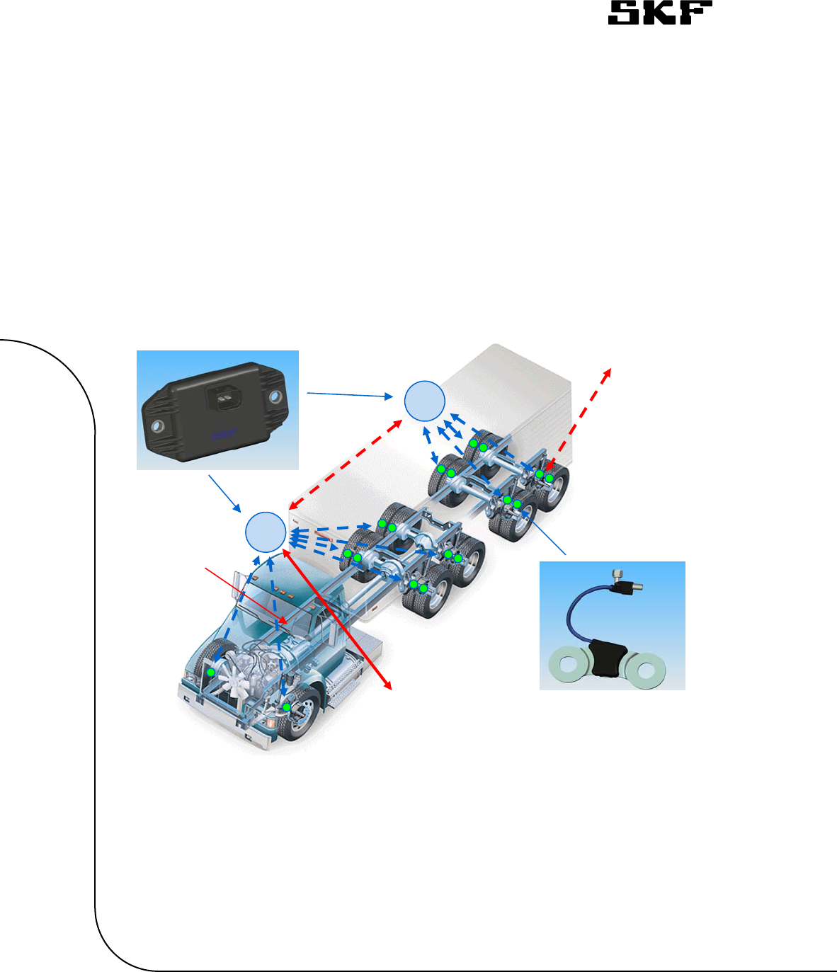
The Tire Pressure Monitoring System, TPMS, monitors tire air pressure and
temperature and displays the information to the driver through the cluster (integrated
system) for commercial vehicles.
Overview picture see Figure 1 - TPMS overview.
Figure 1 - TPMS overview
ECU
_P
Option Hand
Interface
ED
ECU
_S
Truck CAN bus External Wheel module
EWM
Optional
Seperate
display
ED

Automotive Development Centre – Sensor Integration
Project: Volvo TPMS
TPMS Mounting Instructions
Author: Alan Roué,
Last saved: 2017-12-19 13:33
SVN $Rev:: 12424 $ 9 (21)
CONFIDENTIAL (X) / INTERNAL USE ONLY ( )
4.2 End customer benefits
The customer benefits of the system are:
Reduced fuel consumption
Reduced tire wear
Increased safety (reduce risk of tire explosions)
Reduced risk of unplanned stops
Provide a solution for future legislation
4.3 User profiles
The following user profiles are foreseen:
1. Driver:
The user receives different information from the system: actual tire pressure,
under pressure warning, ….
2. Standard service:
The user can update system configurations, for example:
- Warning thresholds
- Vehicle configurations
The standard service user profile is typically used in the fleet workshop.
3. Extended service:
- The user can read the diagnostic memory
- The reset of errors in the diagnostic memory is possible
- The Software of the ECU can be updated
This extended service user profile is typically used in the OEM workshop or in the
OEM production line.
4.4 System applications
The following applications of the system are foreseen.
4.4.1 Driving situation
During driving the system monitors the pressure and the temperature of the different
tires. The tire pressure values are shown on the display. If the tire pressure or wheel
temperature is out of normal range, a warning to the driver is initiated.
In these system applications also vehicle stop phases are included. Vehicle stop phases
are: short breaks, stops for loading/unloading the truck, breaks over a certain time
period (for example weekend).
Also the connection and disconnection of trailers has to be handled by the system. Two
modes are possible.
1. Auto connection: The system determines automatically the connection or
disconnection of a trailer.
2. Manual connection: The truck driver supports the system to detect a new
connected trailer(s) according to system instructions.

Automotive Development Centre – Sensor Integration
Project: Volvo TPMS
TPMS Mounting Instructions
Author: Alan Roué,
Last saved: 2017-12-19 13:33
SVN $Rev:: 12424 $ 10 (21)
CONFIDENTIAL (X) / INTERNAL USE ONLY ( )
4.4.2 Configuration by the end customer
The configuration by the end customer may be necessary after an error condition, for
example a change of a defect system component, after a tire replacement or if a system
component has reached its operating lifetime.
If a tire(s) or a tire sensor(s) is/are changed the learning of the relative position of the
tire sensors in the vehicle is necessary. Two modes are possible:
1. Automatic positioning: The system determines automatically the position of
each tire, based on an algorithm which evaluates several sensor data.
2. Manual positioning: The end customer manually positions the tire sensors
according to system instructions.
If a central receiver on the truck or the optional display is changed or newly installed,
the system has also to be learned-in.
This configuration is usually done in a truck workshop.
4.4.3 Configuration during truck production
During the truck production the wheel sensors are assembled to truck wheels. After this
assembly, the system has to be learned-in the positions of the tire sensors. This has to
be done manually.
If a separate display in the cabin is used, the display must also be paired to the
corresponding central receiver on the truck.
4.4.4 Single tire change on road
If during driving a tire is damaged and has to be changed on the road, the system
automatically assigns the tire sensor to this new tire.
The change of a tire on the road is usually done by the driver or by a tire service
company.
4.4.5 Maintenance, service by the workshop
TPMS EWM is a non reparable module and no software update can be done.
Maintenance is also not feasible. Therefore, at module end of life, it shall be recycled by
the appropriated means.
4.4.6 Caution
Tyre Pressure Monitoring System is not a safety system. Data provided by TPMS system
should be consided as informations. TPMS system does not avoid to have a regular tyre
pressure maintenance.

Automotive Development Centre – Sensor Integration
Project: Volvo TPMS
TPMS Mounting Instructions
Author: Alan Roué,
Last saved: 2017-12-19 13:33
SVN $Rev:: 12424 $ 11 (21)
CONFIDENTIAL (X) / INTERNAL USE ONLY ( )
4.4.7 Information to user
TPMS complies with part 15 of the FCC Rules. Operation is subject to the following two
conditions: (1) This device may not cause harmful interference, and (2) this device
must accept any interference received, including interference that may cause undesired
operation.
Caution: User that changes or modifications not expressly approved by SKF for
compliance could void the user's authority to operate the equipment.

Automotive Development Centre – Sensor Integration
Project: Volvo TPMS
TPMS Mounting Instructions
Author: Alan Roué,
Last saved: 2017-12-19 13:33
SVN $Rev:: 12424 $ 12 (21)
CONFIDENTIAL (X) / INTERNAL USE ONLY ( )
5 TPMS mounting instructions
This chapter describes calibration and installation procedures that shall be executed
when the TPM system is mounted on the assembly line.
Following steps and actions will be necessary to perform a successful installation and
configuration of the TPM system.
Step Action Expected behaviour
1
Place the TPM ECU in the
programming fixture and download
the SW package
(see 5.1)
SW download completed
without issues
2 Mount the TPM ECU on the gearbox
cross member and electrically
connect it to the truck (see 5.2)
3 Mount the appropriate TPM WM
variants to the correct wheel and tire
air valve (see 5.3)
The WMs gets activated
(transmitting RF frames) as
soon as a pressure leap is
detected and as long as the
WMs continue to be
pressurized.
4 Scan the barcode of the WMs to
create a parameter (see 5.6.1)
A parameter with the WMs
ID-number linked with its
position is created and
uploaded to the assembly
server
5 Write the WM ID parameters to the
TPM ECU (see 5.6.2). Parameter programming
complete without issues.
7 Check that no DTCs are present at
EOL No DTC related to TPMS
shall be raised
5.1 SW download
The TPM ECU is delivered without SW implemented. Use the manufacturing
tools to download the SW package (including parameter dataset).
SW download can be performed either by connecting the TPM ECU to
interface of the tool used (direct download), or connecting the OBD plug of
the truck to the interface of the tool used.
Automotive Development Centre – Sensor Integration
Project: Volvo TPMS
TPMS Mounting Instructions
Author: Alan Roué,
Last saved: 2017-12-19 13:33
SVN $Rev:: 12424 $ 13 (21)
CONFIDENTIAL (X) / INTERNAL USE ONLY ( )
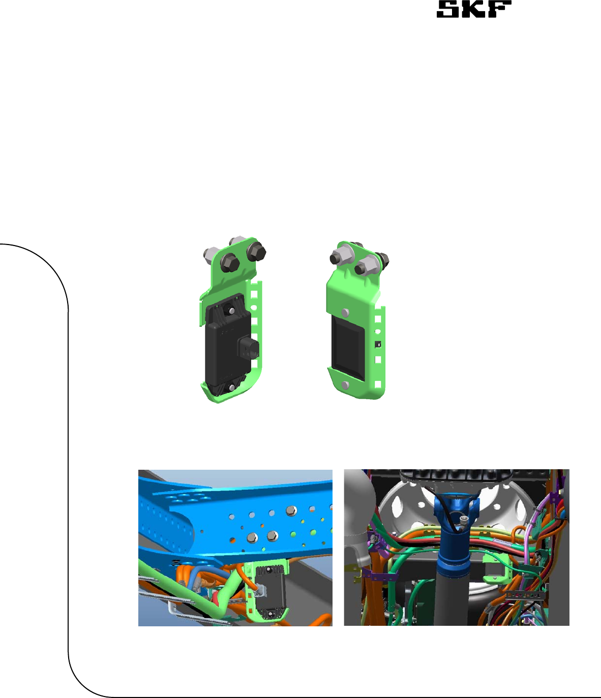
5.2 Mounting the TPM ECU
The TPM ECU is to be positioned on the press screws of the bracket, as
shown in Figure 1.
Note: Tighten the self-locking nut to 24±4 Nm.
Note:
Be careful not to touch or damage the ECU connectors during handling.
The bracket is to be assembled to the chassis (gear box cross member) in
the central part of the vehicle.
Figure 1: Example of TPM ECU mounted on
Figure 2: Example of the TPM ECU assembled on chassis
Automotive Development Centre – Sensor Integration
Project: Volvo TPMS
TPMS Mounting Instructions
Author: Alan Roué,
Last saved: 2017-12-19 13:33
SVN $Rev:: 12424 $ 14 (21)
CONFIDENTIAL (X) / INTERNAL USE ONLY ( )
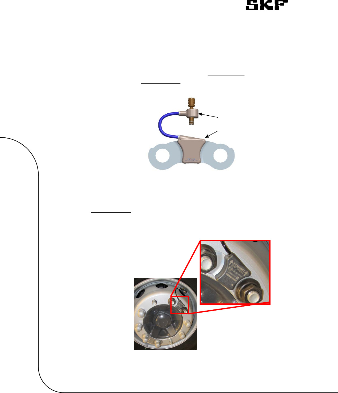
5.3 Mounting the WMs
The TPM WM is made up by two modules; the ‘main module’, with the sheet
metal bracket and the ‘valve module’, containing the pressure sensor. The
two modules are connected to each other by an electrical cable.
The ‘main module’ shall be mounted to the rim and fixated by the standard
wheel nuts. Make sure the arrow marking on the WM is pointing away from
the center of the rim, as illustrated in figure 4 below.
Valve
module
Main
module
Figure 3: Illustration of the TPM WM (straight connector) and
its modules
Figure 4: Illustration showing the correct point of direction for
the arrow marking

Automotive Development Centre – Sensor Integration
Project: Volvo TPMS
TPMS Mounting Instructions
Author: Alan Roué,
Last saved: 2017-12-19 13:33
SVN $Rev:: 12424 $ 15 (21)
CONFIDENTIAL (X) / INTERNAL USE ONLY ( )
Note: The wheel nuts shall be applied with the tightening torque as specified in
TR 1579514 (Volvo standard)
The ‘valve module’ shall be assembled to the tire air valve by tightening the
swirling nut to the tire air valve hand tight. (Recommended tightening torque
approximately 0,3-0,5 Nm)
Note: There shall not be any air leakage present when correctly assembled. Air leakage will
be detected by the system.
Note: Avoid twisting the electrical cable more than 180°.
Note: The electrical cable must not be clamped or damaged during the
assembly of the WM.
The WMs will be delivered in “inactive mode” (=no RF transmission active) and
will require activation (switching from “inactive mode” to “active mode”) to
enable RF communication and successful calibration.
The WMs are activated when a pressure leap is detected, e.g. when getting
mechanically connected to a pressurized air valve.
As from the point when a WM is initially connected to a pressurized air valve
until it gets activated will require 16s. The WMs will stay activated as long as
they are pressurized, e.g. connected to an inflated tire. If the pressure is
removed, the WMs will switch back to “inactive mode” and that will stop the RF
transmission.
Automotive Development Centre – Sensor Integration
Project: Volvo TPMS
TPMS Mounting Instructions
Author: Alan Roué,
Last saved: 2017-12-19 13:33
SVN $Rev:: 12424 $ 16 (21)
CONFIDENTIAL (X) / INTERNAL USE ONLY ( )
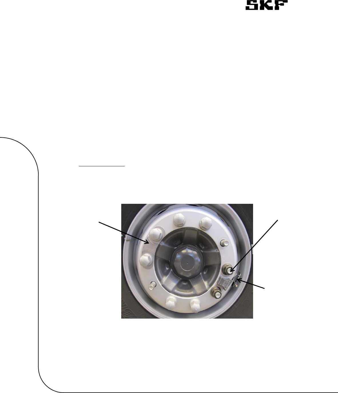
5.4 Front and tag/pusher axle installation with single
mounted wheel
On single mounted wheels the TPM WM shall be positioned on the two wheel
studs closest to the tire air valve, as illustrated in Figure 5 below.
Note: Contact between rim/protection ring and electrical cable is permitted.
5.4.1 Counter weight
The wheel module must not disrupt wheel balance; therefore, the
counterweight shall be mounted on the opposite side (180°) of the TPM WM
on all front axles.
The curvature of the counter weight shall follow the curve of the rim.
Counter Wheel
Air valve
Figure 5: Illustration showing WM and counter weight assembly on single
mounted tires
Automotive Development Centre – Sensor Integration
Project: Volvo TPMS
TPMS Mounting Instructions
Author: Alan Roué,
Last saved: 2017-12-19 13:33
SVN $Rev:: 12424 $ 17 (21)
CONFIDENTIAL (X) / INTERNAL USE ONLY ( )
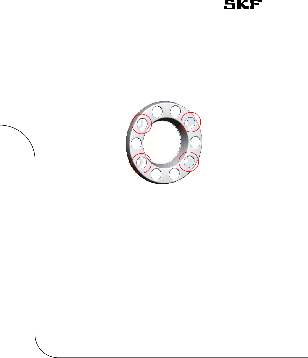
5.4.2 Protecting ring
Make sure that the wheel protecting ring’s attachment point is clear from
the TPM WM. The protecting ring is not to use the same wheel studs as the
TPM WM or counter weight.
5.4.3 Light weight pusher axle (WTP-D245)
On pusher axles with variant WTP-D245 the TPM WM shall be mounted on
the two wheel studs closest to the right next to the tire air valve, as
illustrated in Figure 7 below.
Figure 4: Illustration pointing out the protecting ring's
Automotive Development Centre – Sensor Integration
Project: Volvo TPMS
TPMS Mounting Instructions
Author: Alan Roué,
Last saved: 2017-12-19 13:33
SVN $Rev:: 12424 $ 18 (21)
CONFIDENTIAL (X) / INTERNAL USE ONLY ( )
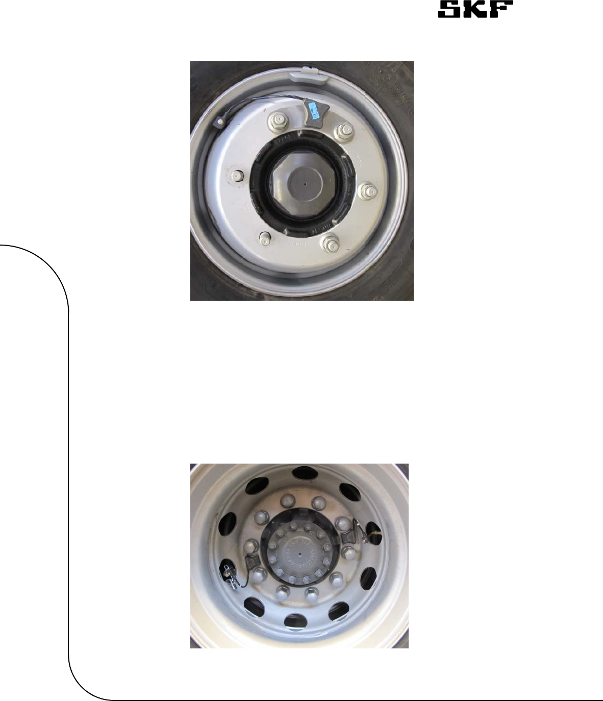
5.5 Rear and tag axle double mounted wheel (WTD-DUAL,
WTT-DUAL)
On dual mounted wheels the two TPM WMs shall be mounted on the
opposite side (180°) of each other. The TPM WMs shall be positioned on the
two wheel studs closest to the tire air valves, as illustrated in Figure 8
below.
Figure 8: Illustration showing WM assembly on dual mounted tires
Figure 7: Illustration showing WM assembly on light weight pusher axle

Automotive Development Centre – Sensor Integration
Project: Volvo TPMS
TPMS Mounting Instructions
Author: Alan Roué,
Last saved: 2017-12-19 13:33
SVN $Rev:: 12424 $ 19 (21)
CONFIDENTIAL (X) / INTERNAL USE ONLY ( )
5.6 Calibration of WMs
Each WM will need to get paired to the TPM ECU and the position defined for
successful TPM installation. This is to be done by scanning the barcode of
each WM, linked with its position, to create a parameter. The parameter is
later written to the TPM ECU on the assembly line, which initiates the pairing
of the activated WMs to the TPM ECU automatically.
5.6.1 Creating the WM id parameter
Create the parameter by scanning the barcode of each mounted WM and
make sure that the WM identification number is linked with correct tire
position.
Note: The WM’s barcode contains information about WM variant (prefix)
and the unique WM identification number, e.g. S 1234567890
Prefix definition:
S: Single mounted tire (straight connector)
O: Dual mounted tire/Outer wheel (135° connector)
I: Dual mounted tire/Inner wheel (90° connector)
5.6.2 Writing WM id parameter and WM calibration
Prerequisites to initiate WM calibration:
All WMs must be activated and within RF range to the TPM ECU
Write the WM id parameter to the TPM ECU, by using the manufacturing
tools, and perform a reset of the TPM ECU.
Note: The writing of the parameter can be performed either by connecting
the TPM ECU to the interface of the tool used (direct download), or
connecting the OBD plug of the truck to the interface of the tool used.
Note: Parameter “P1LWM – TPMS Wheel module identification number” is to
be used for WM identification.

Automotive Development Centre – Sensor Integration
Project: Volvo TPMS
TPMS Mounting Instructions
Author: Alan Roué,
Last saved: 2017-12-19 13:33
SVN $Rev:: 12424 $ 20 (21)
CONFIDENTIAL (X) / INTERNAL USE ONLY ( )
The WM calibration/pairing will automatically start after the TPM ECU reset.
Keep the TPM ECU continuously power supplied for minimum of 3 minutes to
allow all WMs to get paired with the TPM ECU.
Note: The TPM ECU is power supplied in vehicle modes: Pre-running,
cracking and running.
Note: Make sure that the power supply to the TPM ECU is not shut off
during required time period for above pairing to not cause damages to the
non-volatile memory of the TPM ECU.
Note: DTC “U300054 – Electronic Control Unit-missing calibration” will be
set to inactive when the calibration is completed (all WMs have been paired
to the ECU).
5.7 End of line testing
Read out the chassis number from the TPMS ECU and check that it corresponds
to the vehicle chassis number.
Read DTCs from the TPM ECU. Active DTCs shall be remedied and inactive
DTCs shall be cleared.

Automotive Development Centre – Sensor Integration
Project: Volvo TPMS
TPMS Mounting Instructions
Author: Alan Roué,
Last saved: 2017-12-19 13:33
SVN $Rev:: 12424 $ 21 (21)
CONFIDENTIAL (X) / INTERNAL USE ONLY ( )
6 TPMS EWM bordeline risks
6.1 Ignition hazard risk analysis
An ignition risk hazard analysis of SKF Tyre Pressure Monitoring System (TPMS)
External Wheel Module (EWM) had been performed following EN 1127-1 : 2011
harmonized standards.
Conclusion: All TPMS EWM ATEX risks had been assessed and are limited.
6.2 Borderline risks analysis
Following recommendations of ATEX Directive 94/9/EC Guideline – 4th Edition –
September 2012 (update December 2013), a borderline analysis had been performed
reviewing potential additional risks compared to Ignition hazard risk analysis.
All listed items had been reviewed and no borderline risk had been identified.
Other potential risks (not listed in ATEX Directive guideline) had been investigated but
no other risk had been kept as applicable.
Conclusion: No residual ATEX risks are applicable to TPMS EWM.