SKSpruce Technologies SAC700E Intelligent Multi-Service Controller User Manual
SKSpruce Technologies Co., Ltd. Intelligent Multi-Service Controller
User manual

http://www.skspruce.com/
San Jose
1885 Lundy Ave., Suite 270,
San Jose, CA 95131, USA
Tel: +1 (408) 449-5604
SAC700E INTELLIGENT
MULTI-SERVICE
CONTROLLER
INSTALLATION MANUAL
Hong Kong
15K International Industrial
Centre, 2-8 Kwei Tei Street,
Shatin, Hong Kong
Tel: +852 26983874
Chengdu
A1, Tianfu Software Park,
1129 Century City Road,
High-tech Zone, Chengdu,
Sichuan, P.R. China
Tel: +86 28 85231119
Revision: 1
Issued on 2016-12-15
SKSpruce Technologies

No part of this documentation may be reproduced in any form or by any means or used to make any
derivative work (such as translation, transformation, or adaptation) without prior, express and written
permission from our company, Inc.
Our company reserves the right to revise this documentation and to make changes in content from
time to time without obligation on the part of our company to provide notification of such revision or
changes.
Our company provides this documentation without warranty of any kind, implied or expressed,
including but not limited to, the implied warranties of merchantability and fitness for a particular
purpose. Our company may make improvements or changes in the product(s) and/or the program(s)
described in this documentation at any time.
UNITED STATES GOVERNMENT LEGENDS:
If you are a United States government agency, then this documentation and the software described
herein are provided to you subject to the following:
United States Government Legend: All technical data and computer software is commercial in nature
and developed solely at private expense. Software is delivered as Commercial Computer Software as
defined in DFARS 252.227-7014 (June 1995) or as a commercial item as defined in FAR 2.101(a)
and as such is provided with only such rights as are provided in our company’s standard commercial
license for the Software. Technical data is provided with limited rights only as provided in DFAR
252.227-7015 (Nov 1995) or FAR 52.227-14 (June 1987), whichever is applicable. You agree not to
remove or deface any portion of any legend provided on any licensed program or documentation
contained in, or delivered to you in conjunction with, this User Guide.

Contents
SAC700E Wireless Access Controller Installation Manual
1
Contents
1 Installation Environments ........................................................................................................................ 3
1.1 Security Precautions ........................................................................................................................ 3
1.1.1 Security Advisories .................................................................................................................. 3
1.1.2 ESD Protection ........................................................................................................................ 3
1.1.3 Security Consideration for the Use of Laser............................................................................ 4
1.2 Tool List ............................................................................................................................................ 4
1.3 Environment Requirements .............................................................................................................. 4
1.4 Operator Requirements .................................................................................................................... 5
2 Unpacking and Inspections ..................................................................................................................... 6
2.1 Product Introductions ....................................................................................................................... 6
2.2 Unpacking Inspections and Assembly ............................................................................................. 7
3 Frame Installations .................................................................................................................................. 8
3.1 Frame Dimensions ........................................................................................................................... 8
3.2 Frame Installations ........................................................................................................................... 8
3.3 Frame Ground Connections ............................................................................................................ 11
4 Installing and Removing Components .................................................................................................. 12
4.1 Installing CM-2XGEF/CM-4GEF Extended Module (optional) ....................................................... 12
4.2 Installing/Removing SFP Module ................................................................................................... 13
5 Cable Connection .................................................................................................................................. 15
5.1 Cable Type ..................................................................................................................................... 15
6 Power On/Off ......................................................................................................................................... 17
6.1 AC Power On/Off ............................................................................................................................ 17
6.2 DC Power Switch ........................................................................................................................... 17
7 Specifications ........................................................................................................................................ 18
7.1 Chasis Specifications ..................................................................................................................... 18
Installation Environments
SAC700E Wireless Access Controller Installation Manual
2
Preface
Audience
This publication is for experienced network managers to configure and manage the
AP under local forwarding or centrol forwarding mode.
Symbol
Symbol Descriptions
Bold The CLI command is Bold.
Italic The secondary title is in Italic.
Courier New Courier New.
Example:
# ping -t 10.10.10.1
Change Records
Version Issue Date Remarks
01 2015.04.24 Version 01
02 2016.02.18 Version 02

Installation Environments
SAC700E Wireless Access Controller Installation Manual
3
1 Installation Environments
1.1 Security Precautions
To avoid personal injury and equipment damage, please carefully read the following
safety precautions before installations.
1.1.1 Security Advisories
Make sure the ground dry and smooth.
Keep the chassis clean and dust-free.
Keep the chassis away from radiator and heat source.
Keep the chassis and installation tools not in walking areas.
Before moving the chassis, remove the internal lines such as the power line.
To prevent any surface damage, please avoid friction between equipment.
Use only local and national electrical codes to upgrade the equipment.
1.1.2 ESD Protection
The equipment contains ESD sensitive devices and ESD can cause equipment and
its parts seriously damaged. Please avoid electrostatic discharge damage according
to the following precautions:
When unpacking, please remove the anti-static packing material components after
the installation devices are ready. Before removing the anti-static packing, please
make sure to use earth tape to discharge the static electricity of the body.
Before moving a sensitive device, please place it into the antistatic container or using
anti-static packing.
If possible, even in the absence of electrostatic environment, please always use anti-
static mat and work mat to handle any sensitive devices.
Please follow the steps below when putting on anti-static bracelet:
Wear the anti-static bracelet.
Fasten the anti-static bracelet, and ensure the antistatic bracelet keeping good
contact with the skin.
Ensure the anti-static bracelet grounding end inserting into the ground, and good
contact between the antistatic bracelet and the ground.
Installation Environments
SAC700E Wireless Access Controller Installation Manual
4
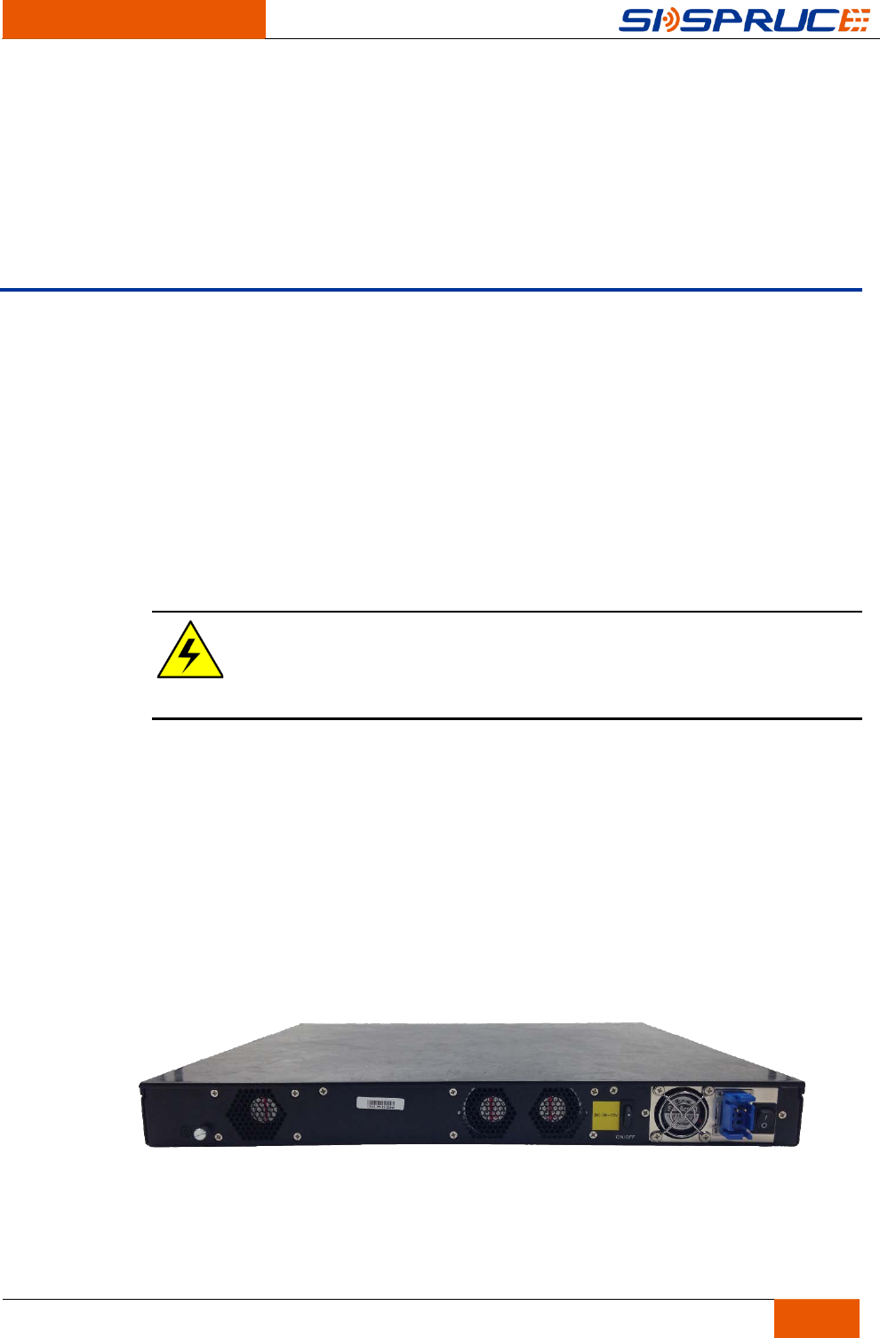
1.1.3 Security Consideration for the Use of Laser
The equipment supports optical interface. When using the optical fiber in upgrade
operation, pay attention not to look directly into the optical interface.
Caution:
Optical fiber laser hurts eyes.
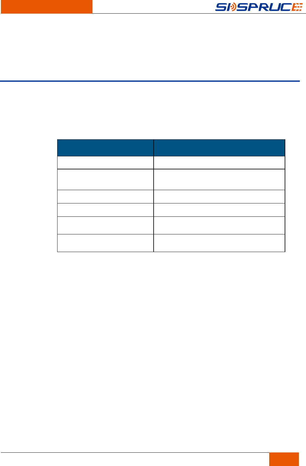
1.2 Tool List
Table 1-1 Tool list
Tool Usage
Cross Screwdriver Cross Screw Drive
Straight Screwdriver Straight Screw Drive
Anti-Static Bracelet Anti-Static Electricity
Optical Fiber Cleaning Kit Optical Fiber Cleaning
Caution:
The tools mentioned above are not delivered with the equipment.
1.3 Environment Requirements
To ensure the normal operation and prolong its service life, please ensure meet the
following installation environment requirements.
Table 1-2 Environment requirements
Item Unit Range
Temperature
℃
0 to 40
Relative Humidity % 5 to 85 (Non-condensing)
Air Pressure kPa 70 to 105 (Air pressure of 70 kPa is
equivalent to 3000 m above sea level.)
Place the board in a clean and ventilated environment. The installation site should be
far away from radiators and heat sources and without conductive dust, corrosive gas
and explosives. Please do not place the equipment in dusty environment, or may
clog the filter, and reduce the cooling efficiency.

Installation Environments
SAC700E Wireless Access Controller Installation Manual
5
1.4 Operator Requirements
Operators need to meet the following requirements:
Basic knowledge of equipment test and operation.
Basic knowledge of laser operation, ESD and electronic appliances.
Basic knowledge of using installation tools.
Experienced service engineers in communication technology or other relative fields.
Fully understand and seriously take security standards.
Unpacking and Inspections
SAC700E Wireless Access Controller Installation Manual
6
2 Unpacking and Inspections
2.1 Product Introductions
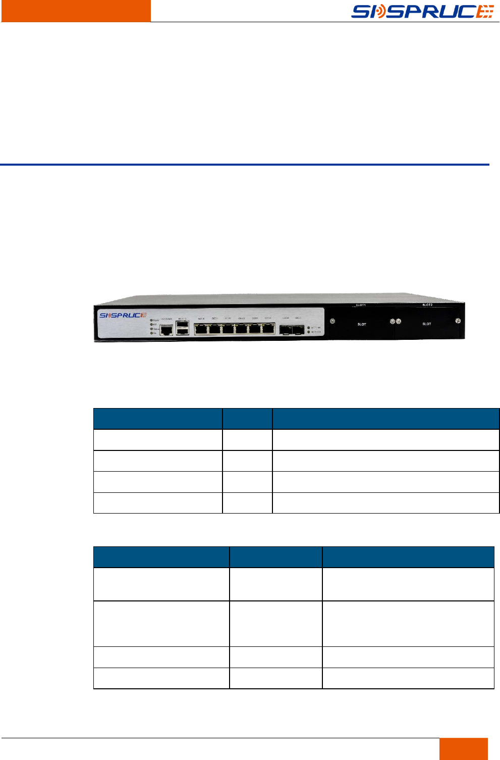
Figure 2-1 Product figure
The appearance of the product is as the above figure.
Table 2-1 The front panel
Name No. Description
USB 2 Managing CPU
Serial port 1 Adjusting CPU
Network port 6 Data transmission.
Optical port 8 Data transmission.
Table 2-2 Indicators
Name Status Description
Power Steady Green The chassis and board are both in
normal power supply
DM Yellow Self-checking indicator
Status Yellow System status indicator
HA Yellow Master-backup indicator
Unpacking and Inspections
SAC700E Wireless Access Controller Installation Manual
7
2.2 Unpacking Inspections and Assembly
Follow these steps to unpack each container for delivery:
Before unpacking and sign for delivery, check damage of each container in transport.
Any damage claim should be in accordance with the procedure that the carrier
releases.
According to the packing list, check each package and its components, verify all the
items, and make sure all the items are in good condition.
The equipment packaging item list is as following:
1U Equipment
Assembly parts (hangers and screws)
AC Power Line
SFP module (optional)
Debugging Cable
A set of documents
Warnings:
This equipment contains sensitive devices. To prevent electrostatic damage, please
wear anti-static bracelet.

Frame Installations
SAC700E Wireless Access Controller Installation Manual
8
3 Frame Installations
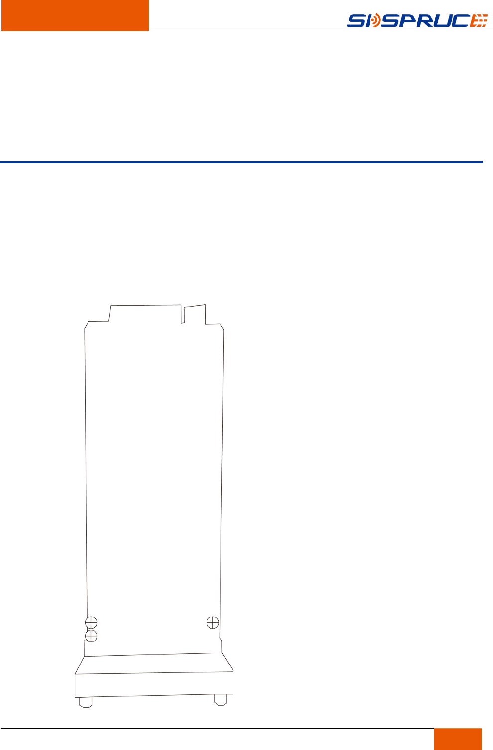
3.1 Frame Dimensions
The equipment can be installed in a standard 19-inch (48.26 cm) frame. The 19-inch
frame, released on August 24th, 1992, must accord with the standard of EIA - 310 -
D. Each case is 22.50 inches tall (57.16 cm). This is equivalent to about 13 frame
installation units. (RMUs: 1RMU = 1.75 inches =4.45 cm)
Frame installation security requirement is as shown below:
The frame or cabinet must meet the laws and regulations of all electrical and
mechanical security in the installation country.
The products installed on frame and the frame must connect grounded correctly and
ensure the ground connection is established in the process of normal use.
Shut off the power before building the power connection.
It is suggested that the circuit breaker sho uld be installed on the top of each frame.
The circuit breaker is designed as automatic operation electric switch to protect from
circuit overload or short circuit caused damages. Its basic function is to detect fault
conditions and immediately break the current by interrupting the continuity after a
fault condition is detected. The 2 circuit breakers on the frame are for each case.
3.2 Frame Installations
The frame installation is under the following steps:
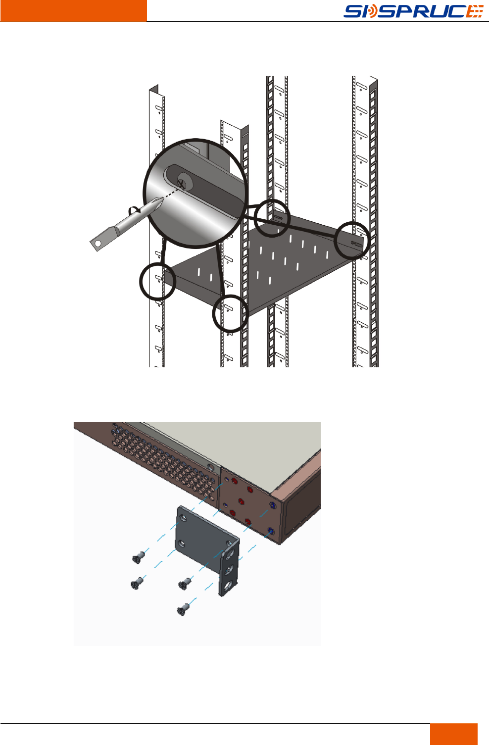
Step 1 Tighten all the frame installation trays with M6 screws to support the safety and
ensure not over tightened.
Frame Installations
SAC700E Wireless Access Controller Installation Manual
9
Figure 3-1 Frame Tray Installations
Step 2 Install the hanggers onto the equipment.
Figure 3-2 Left hanger installations
Frame Installations
SAC700E Wireless Access Controller Installation Manual
10
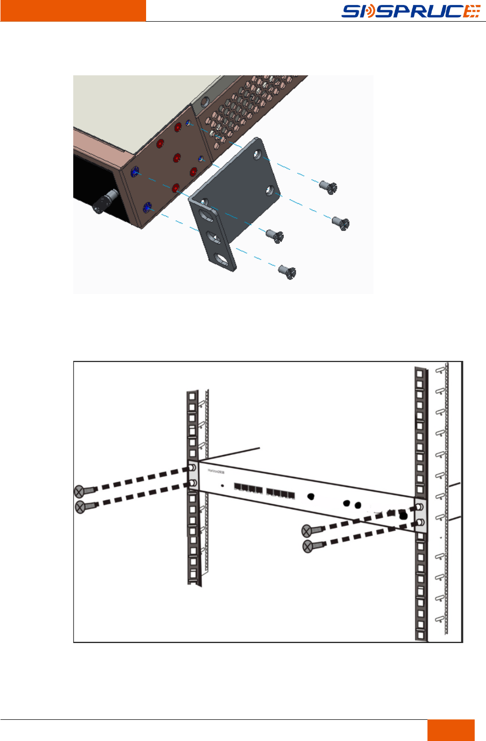
Figure 3-3 Right hanger installations
Step 3 Install the equipment onto the 19-inch frame and tighten it with 4 screws as shown
below.
Figure 3-4 Tighten the Nut
Frame Installations
SAC700E Wireless Access Controller Installation Manual
11
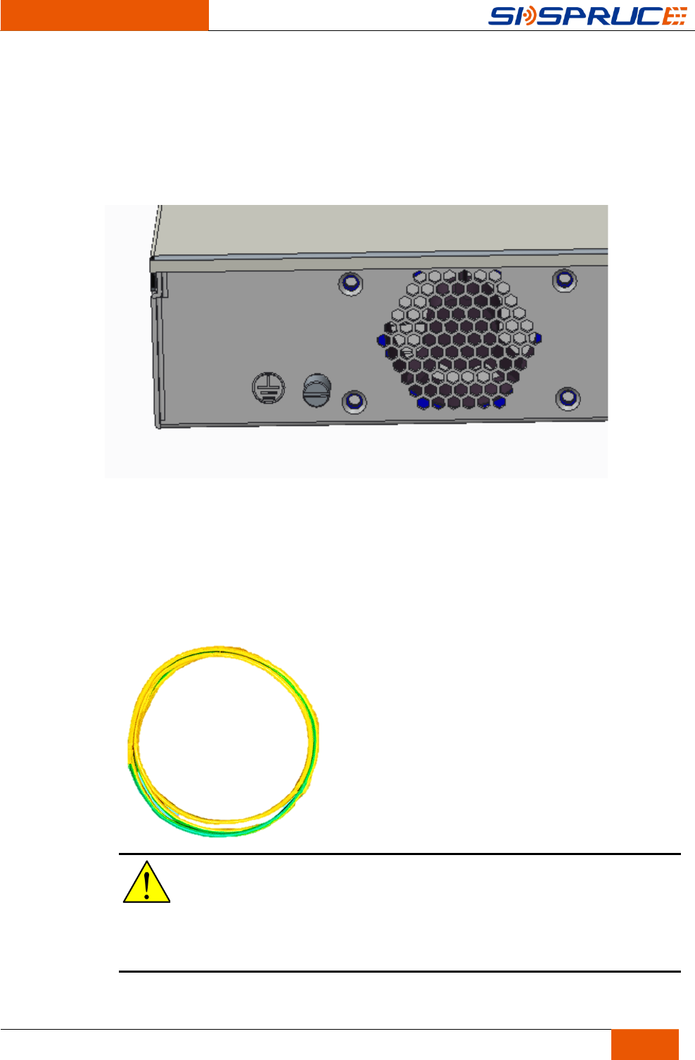
3.3 Frame Ground Connections
The equipment provides 2 M6 frame ground ends on the bottom of the frame as
shown below.
Figure 3-5 Frame Ground Ends
Frame Ground Cable Dimensions:
Cable Size: AWG6
End: 45° Tongue Connection End
Frame Grounding Cable
Figure 3-6 Frame Ground Cable
Caution:
Frame ground connection must accord with the applicable standard, the local
requirements and the company's regular installation methods. All the ground
connections must be anti-oxidation coated.
Installing and Removing
Components
SAC700E Wireless Access Controller Installation Manual
12
4 Installing and Removing Components
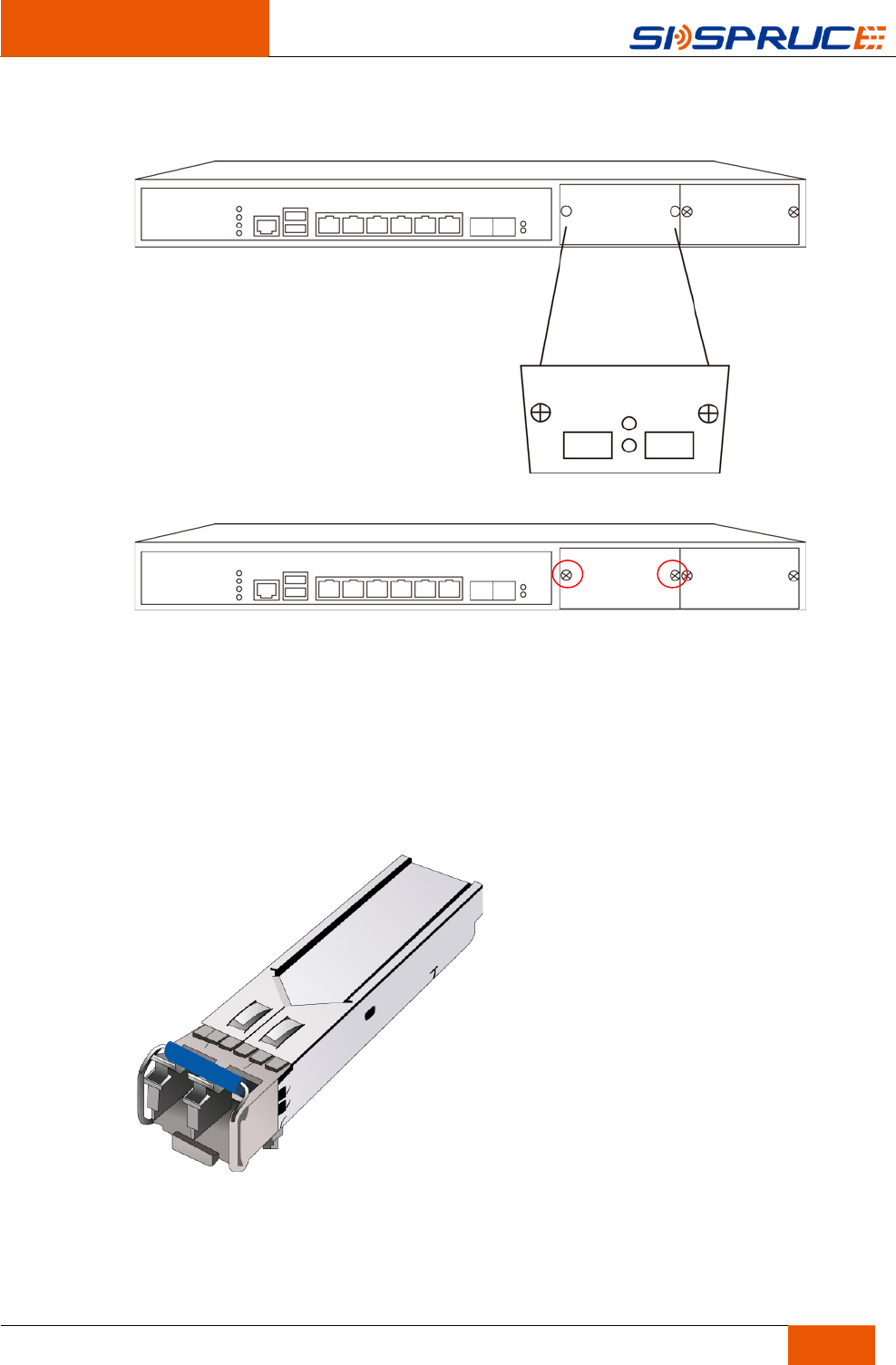
4.1 Installing CM-2XGEF/CM-4GEF Extended Module
(optional)
The 2 installation methods are the same. Set CM-2XGEF module installation as an
example to describe the installation steps of extended module.
Step 1 Fix the module and the installation plate with 3 M2.5x6 screws.
Installing and Removing
Components
SAC700E Wireless Access Controller Installation Manual
13
Remove one blank panel on the slot (set slot0 as an example) and push the extension
plate into the slot as shown below.
Step 2 Tighten the screw on the panel to complete the installation.
4.2 Installing/Removing SFP Module
The equipment supports GE ports and 10 GE Ethernet ports on the small form factor
pluggable (SFP) optical module. GE port can also support copper SFP modules as
shown in the following figure:
Figure 4-1 Fiber SFP Module
Installing and Removing
Components
SAC700E Wireless Access Controller Installation Manual
14
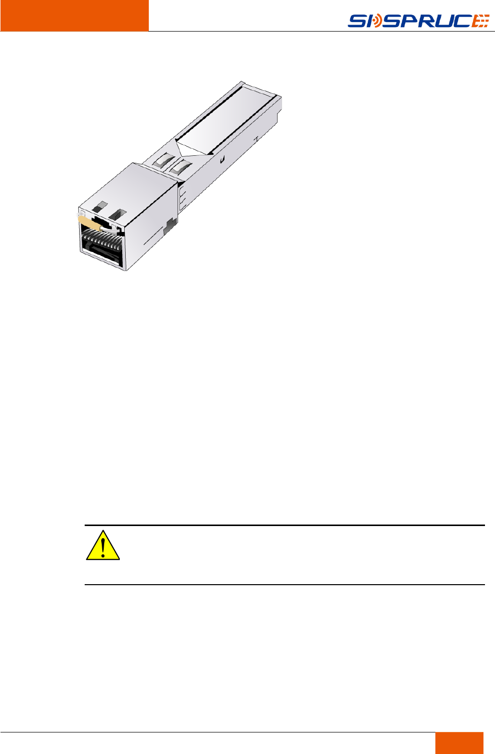
Figure 4-2 Copper SFP Module
Please notice the following when install/remove SFP modules:
Slowly and carefully insert all modules to avoid damages.
Slightly install/remove SFP Module to avoid serious module and card damages.
Please unlock the locking mechanism before removing the SFP modules on card
to avoid damages.
Install SFP modules as the following steps:
Step 1 Remove the black dust plug on the port(the dust plug can be used multiple times)
Step 2 Insert the SFP module into the corresponding port and ensure using the locking
mechanism.
Remove SFP modules as the following steps:
Step 1 Unlock the locking mechanism and pull the handle outward on the SFP module.
Step 2 Pull the SFP card handle.
Step 3 Install the dust plug into the empty interface.
Caution:
Please do not power off when installing/removing the SFP module.
Cable Connection
SAC700E Wireless Access Controller Installation Manual
15
5 Cable Connection
5.1 Cable Type
There are three kinds of cables which need to be established during the equipment
cable connection
• Optical fiber
• Ethernet cable
• Console cable
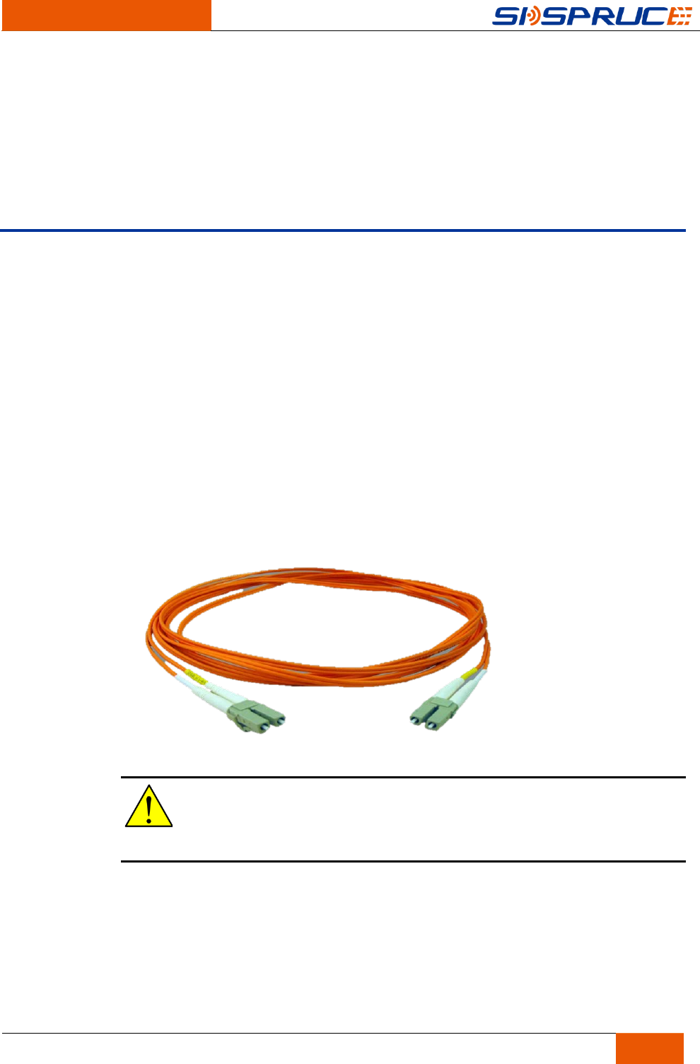
Optical Fiber
The equipment GE ports and 10GE ports support SFP modules with LC connectors
to establish fiber connections.
Figure 5-1 Optical fiber
Caution:
Optical fiber will not be shipped with the equipment.
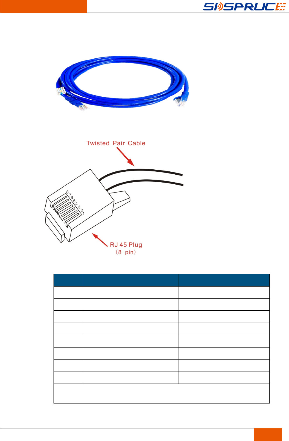
Ethernet cable
The equipment uses Category 5 (CAT 5) Ethernet cable with RJ 45 connectors to
establish electrical Ethernet connections.
Cable Connection
SAC700E Wireless Access Controller Installation Manual
16
Figure 5-2 Ethernet cable
Figure 5-3 RJ45 connector
Table 5-1 RJ45 interface pin
Pin 100Base-Tx 100Mbps Cat5 1000Base-Tx 1Gbps Cat5
1 TX+ BI DA+
2 TX- BI DA-
3 RX+ BI DB+
4 Na BI DC+
5 Na BI DC-
6 RX- BI DB-
7 Na BI DD+
8 Na BI DD-
RX=Receive Data TX=Transmit Data BI=BI directional data
DA,DB,DC,DD=Data Pair A,B,C and D
Power On/Off
SAC700E Wireless Access Controller Installation Manual
17
6 Power On/Off
6.1 AC Power On/Off
The SAC700E equipment uses ATX power switch. After the power cord connected
properly, if the last power status is off, the equipment will power on directly and if the
last power status is ATX On/Off, click on the ATX power switch to power on the
equipment.
After system boot starts, the fan will rotate faster than when it normally works, and all
the LED lights on card and module will flash. After a period of time (up to one
minute), the fan speed returns to normal working state, and the corresponding
indicator shuts down.
Warnings:
Do not touch the power supply side when power on the system.
Push ATX power switch to power off the equipment. The equipment will save the data
and close the related process and then power off.
6.2 DC Power Switch
The DC version equipment has 2 power switches: 1.AT switch; 2.ATX switch as
shown below:
Figure 6-1 Power switch
The AT switch is on the DC power module. You can disable the DC power supply.
For the use of ATX power swith, please refer to the descriptions in the previous
chapter.
Specifications
SAC700E Wireless Access Controller Installation Manual
18
7 Specifications
7.1 Chasis Specifications
Table 7-1 Chasis Specifications
Item Description
Type 1 U
Dimensions (W x D x H) 450 mm x 440 mm x 44 mm
Interface 6 x RJ45 or 2 x SFP
Weight (full loaded) 6.25 kg
Power supply (AC) 100 V ~240 V AC,50 Hz~60 Hz
DC power supply (optional) 36 V~72 V DC
7.2 Certifications
The following table lists the certifications of the SAC700E.
Specifications
SAC700E Wireless Access Controller Installation Manual
19
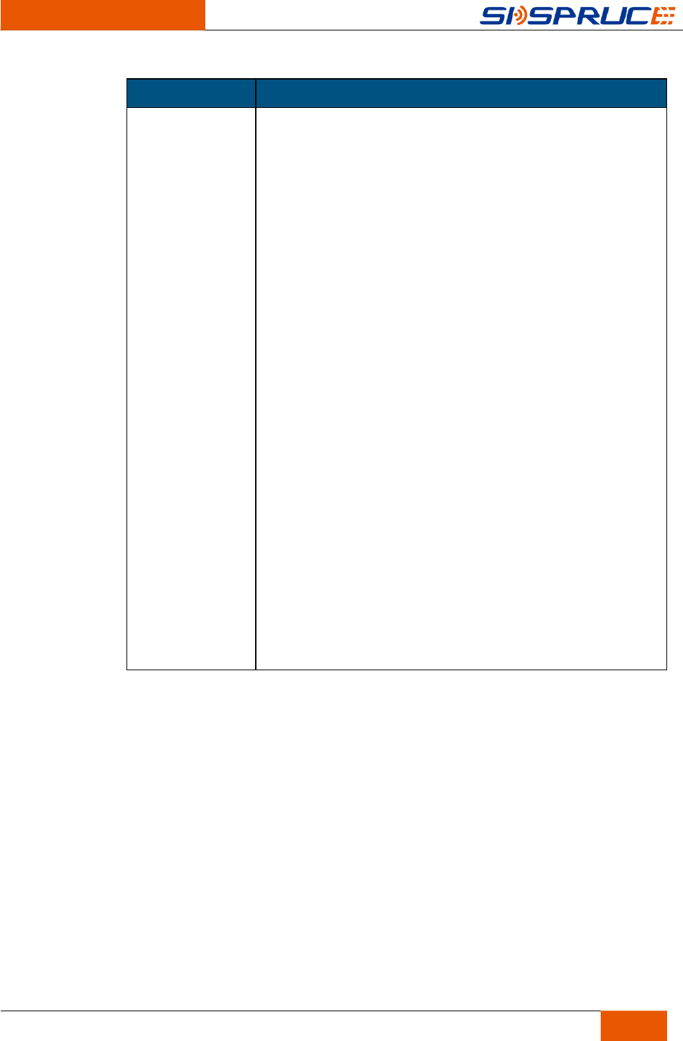
Certification Description
FCC This equipment has been tested and found to comply with the
limits for a Class B digital device, pursuant to part 15 of the
FCC Rules. These limits are designed to provide reasonable
protection against harmful interference in a residential
installation. This equipment generates, uses and can radiate
radio frequency energy and, if not installed and used in
accordance with the instructions, may cause harmful
interference to radio communications. However, there is no
guarantee that interference will not occur in a particular
installation. If this equipment does cause harmful interference
to radio or television reception, which can be determined by
turning the equipment off and on, the user is encouraged to
try to correct the interference by one or more of the following
measures:
• Reorient or relocate the receiving antenna.
• Increase the separation between the equipment and
receiver.
• Connect the equipment into an outlet on a circuit different
from that to which the receiver is connected.
• Consult the dealer or an experienced radio/TV technician
for help.
Caution: Any changes or modifications to this device not
explicitly approved by manufacturer could void your authority
to operate this equipment.
This device complies with part 15 of the FCC Rules.
Operation is subject to the following two conditions: (1) This
device may not cause harmful interference, and (2) this
device must accept any interference received, including
interference that may cause undesired operation.

Specifications
SAC700E Wireless Access Controller Installation Manual
20
Abbreviations
A
AC
ACL
AP
Alternating Current
Access Control List
Access Point
C
CAPWAP
D
DHCP
M
MAC
N
NAT
R
RFC
S
SSID
V
VLAN
W
WEP
WPA
Control And Provisioning of Wireless Access Points
Dynamic Host Configuration Protocol
Multi-Access Computer
Network Address Translation
Request For Comments
Service Set Identifier
Virtual Local Area Network
Wired Equivalent Privacy
Wi-Fi Protected Access