SKYPINE ELECTRONICS CNE8215BCL Car Navigation Entertainment System User Manual IV
SKYPINE ELECTRONICS (SHEN ZHEN) CO., LTD. Car Navigation Entertainment System IV
Contents
- 1. User Manual
- 2. User Manual Part II
- 3. user manual III
- 4. user Manual IV
user Manual IV
English
NX500/NZ50042
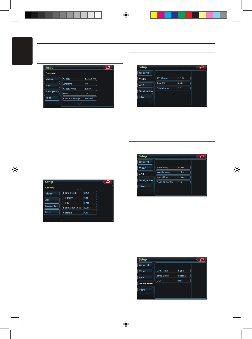
Press [Setup] button on the Main Menu screen.
The Setup menu screen will be displayed.
General Setup Menu
Clock: Touch the button to set the clock.
Select Clock Mode 12 Hr.
AM/PM: Touch the button to change
AM or PM, when 12Hr mode is
selected.
Beep: The function of it is to choose the
Beep voice on or off.
Camera Image: The Function of it is to choose
the mode of camera image normal or
mirror.
Radio Field: The function of it is to choose the
radio mode in the country you are. It’s
contain USA, Europe, S. America,
Other.
Tel Mute: The function of it is to set the
Bluetooth ready on or off .
Tel SP: The function of it is to set the speaker
of the Bluetooth ready front left or
front right.
Auxin Input SW: The function of it is to choose
the auxin input switch, including Low,
Mid, High.
Version: Display the software version
information.
Video Setup Menu
This menu includes: TV Shape; Aux IN;
Brightness.
TV Shape: The function of it is to choose the
screen area shape - 4:3 or 16:9.
Aux IN: The function of it is to choose Aux In
format. It contains AUTO, PAL, NTSC.
Brightness: Set brightness value from 0 to 20.
ASP Setup Menu
This menu includes: Bass Freq; Treble Freq; Sub
Filter; Bass Q-Factor.
Bass Freq: Choose the desired bass frequency.
60Hz, 80Hz, 100Hz, 200Hz
Treble Freq: Choose the desired treble
frequency 10KHz/12.5KHz/1 5KHz/
17.5KHz.
Sub Filter: Choose the desired Sub Filter
frequency: 80Hz/120Hz/160Hz.
Bass Q-Factor: Choose the Bass
Q-Factor:1.0/1.25/1.5/2.0.
Navigation Setup Menu
This menu includes: GPS Time, Time Zone, DST
Setup Operations
NX_NZ500 0608.findd 4 6/16/2009 8:06:22 AM
English
NX500/NZ500 43
GPS Time: Use this function of it is to
synchronize the GPS time or not.
It contains two choices: Ignore and
Sync.
Time Zone: Choose the desired Time Zone:
NTF/Atlabtic/Eastern/Central/
Mountain/Pacific/Alaska.
DST: Use this function to set Daylight Saving
Time on or off.
Misc Set Up
This menu include: TS Calibrate; Set Password;
Parental control.
TS Calibrate: The function of it is to select the
TS Calibrate YES or NO.
Set password: The function of it is to set the
password of the child lock.
Parental control: The function of it is to set
the rating of the age. It contains
Kid Saf/G/PG/PG- 13/PG-R/R/
NC- 17/Adult.
Software Update: Choose the function to
update the software.
NAV Update: Choose the function to
update the NAV software.
Load Factory: The function is to select to load
factory default or not.
DVD Region: Choose DVD region.
Parking Det.: The function of it is to select
parking det. mode. Select: Ignore,
Level and Seq.
Macrovision: The function of it is to select
macrovision ON or OFF.
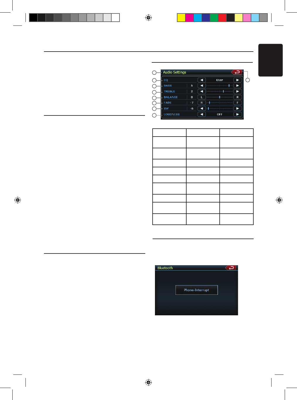
Phone Menu
If you receive a phone call and the Bluetooth
is On, the screen will display Phone Interrupt
Menu.
1. Press the right top corner to go back to Main
Menu.
2. Touch [Setup] button to set Tel Mute and
Tel SP.
EQ Set Up
Monitor OFF Menu
Press Monitor OFF icon on Main Menu, it will
show “Standing By”. Touch the screen to turn
the monitor ON. Tuch the screen again to turn it
OFF.
Setup Operations
No. Button Name Function
1 Title Name Display title
name
2 Back Button Close the Audio
Settins menu
3 EQ Set EQ mode
4 BASS Set bass value
5 TREBLE Set treble value
6 BALANCE Set balance
value
7 FADER Set fader value
8 SW Set Sub Woofer
value
9 LOUDNESS Set loudness
on or off
1
3
4
5
6
7
8
9
2
NX_NZ500 0608.findd 4 6/16/2009 8:06:22 AM
English
NX500/NZ50044
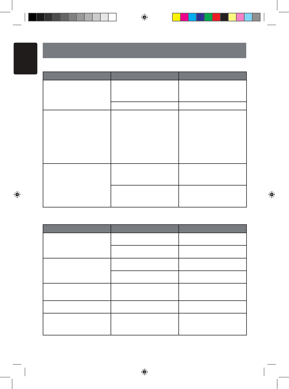
8. TROUBLESHOOTING
GENERAL
DVD PLAYER
Problem Cause Measure
Power does not turn on. (No
sound is produced.) Fuse is blown. Replace with a fuse of the
same amperage. If the fuse
blows again, consult your store
of purchase.
Incorrect wiring. Consult your store of purchase.
Nothing happens when buttons
are pressed.
Display is not accurate.
The microprocessor has mal-
functioned due to noise, etc. Turn off the power and open
the operation panel. Press the
reset button with a thin rod.
Note:
When the Reset button is
pressed, turn off the ACC
power.
* When the Reset button is
pressed, frequencies of radio
stations, titles, etc. stored in
memory are cleared.”
The remote control unit does
not work. Direct rays of the sun fall on
the light-receptive part of the
remote control unit.
When direct rays of the sun fall
on the light-receptive part of
the remote control unit, it may
not work.
The batteries of the remote
control unit are dead or there is
no battery in the remote control
unit.
Check the batteries of the
remote control unit.
Problem Cause Measure
Disc cannot be loaded. Another disc is already loaded. Eject the disc before loading
the new one.
There is a foreign matter
already in place. Eject the foreign matter forcibly.
Sound skips or is noisy. Compact disc is dirty. Clean the compact disc with a
soft cloth.
Compact disc is heavily
scratched or warped. Replace with a compact disc
with no scratches.
Sound is bad directly after
power is turned on. Water droplets may form on
the internal lens when the car
is parked in a humid place.
Let dry for about 1 hour with
the power on.
The image is not displayed. The parking brake is not
engaged. Check that the parking brake is
engaged.
Disc cannot play with the
display “PARENTAL VIOLA-
TION” shown.
Feature exceeds set parental
level. Release the view limitation or
change the parental level.
See the subsection “Setting up
the parental level”
NX_NZ500 0608.findd 44 6/16/2009 8:06:23 AM
English
NX500/NZ500 45
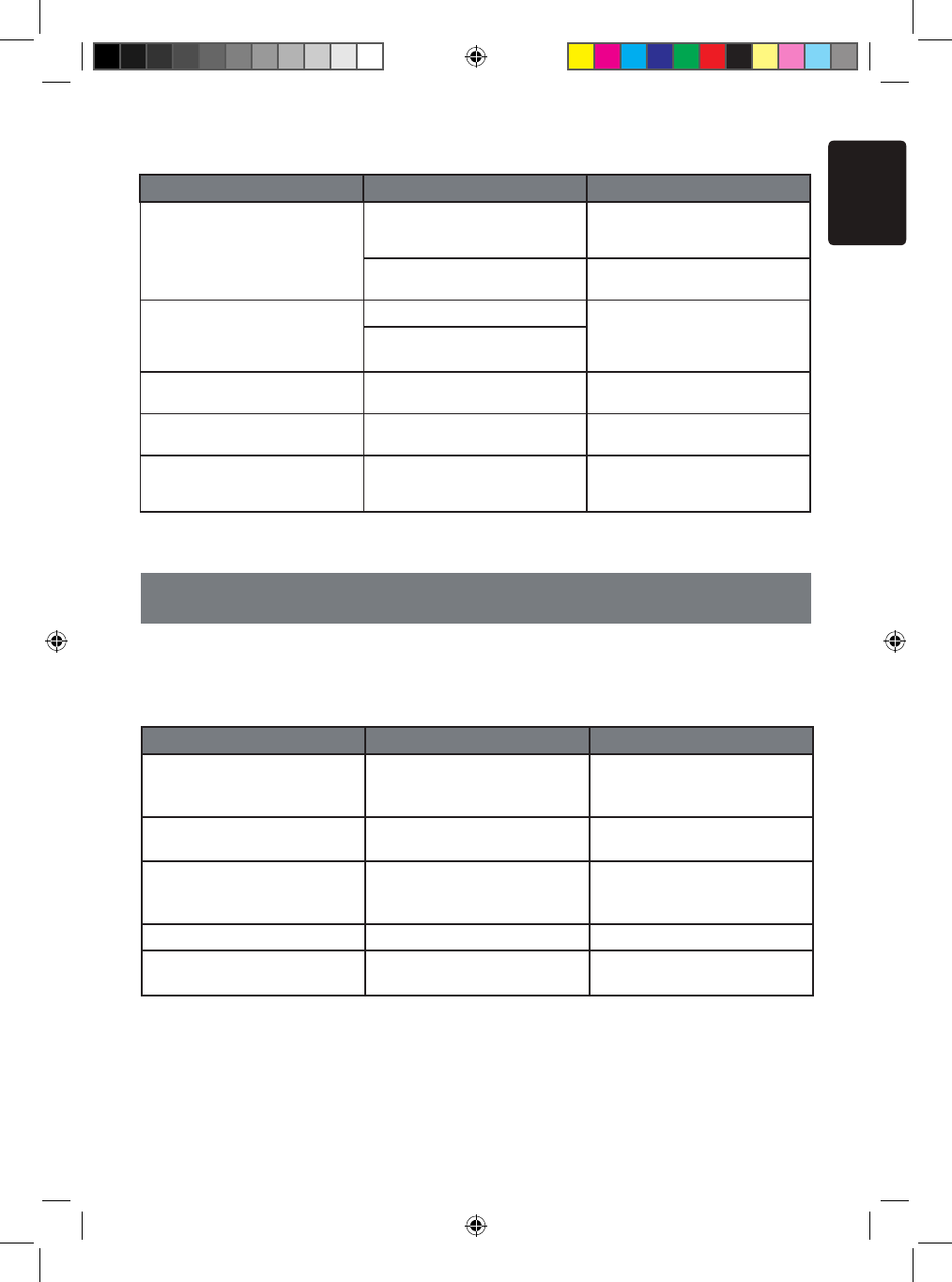
USB DEVICE
Problem Cause Measure
USB device cannot be in-
serted. The USB device has been
inserted with wrong direction. Reversing the connection
direction of the USB device, try
it again.
The USB connector is broken. Replace with a new USB
device.
USB device is not recognized. The USB device is damaged. Disconnect the USB device
and reconnect. If the device is
still not recognized, try replac-
ing with a different USB device.
Connectors are loose.
No sound heard with the dis-
play “NO FILE” shown. No MP3/WMA/AAC file is
stored in the USB device. Store these files properly in the
USB device.
Sound skips or is noisy. MP3/WMA/AAC files are not
encoded properly. Use MP3/WMA/AAC files
encoded properly.
The iPod/iPhone’s video
image is disturbed. The TV Signal setting of the
iPod/iPhone is not set correctly. Set the TV Signal setting
(NTSC/PAL) of the iPod/iPhone
correctly.
9. ERROR DISPLAY
If an error occurs, one of the following displays is displayed.
Take the measures described below to solve the problem.
DVD PLAYER
Display Cause Measure
BAD DISC A disc is caught inside the CD
deck and is not ejected.
This is a failure of DVD deck’s
mechanism and consult your
store of purchase.
BAD DISC A disc cannot be played due to
scratches, etc.
Replace with a non-scratched,
non-warped disc.
BAD DISC A disc is loaded upside- down
inside the DVD deck and does
not play.
Eject the disc then reload it
properly.
PARENTAL VIOLATION Parental level error Set the correct Parental level.
WRONG REGION Region code error Eject the disc, and replace cor-
rect region code disc.
If an error display other than the ones described above appears, press the Reset button.
If the problem persists, turn off the power and consult your store of purchase.
* When the Reset button is pressed, frequencies of radio stations, titles, etc. stored in
memory are cleared.
NX_NZ500 0608.findd 45 6/16/2009 8:06:23 AM
English
NX500/NZ50046
10. SPECIFICATIONS
FM Tuner
Frequency Range: 87.9 MHz to 107.9 MHz
Usable Sensitivity: 8 dBµV
50dB Quieting Sensitivity: 14 dBµV
Alternate Channel Selectivity: 70 dB
Stereo Separation: 25 dB (1 kHz)
Frequency Response: 30 Hz to 15kHz
AM Tuner
Frequency Range: 530 kHz to 1710 kHz
Usable Sensitivity: 28 dBµV
DVD Player System
Digital Versatile Disc System with CDDA
capable
Usable discs:
DVD video disc, Compact disc
Frequency Response: 20 Hz to 20 kHz
Sound/Noise Ratio: 95 dbA (1W Ref)
Dynamic Range: 95 dB (1 kHz)
Distortion: 0.05%
Video system: NTSC
Digital Versatile Disc System
Navigation
Memory: 2GB Flash Memory
Upgrade Platform: USB
3D Display Mode: 3D maps, 3D landmarks,
3D icons
User Mode: Simple mode, Advanced mode
TTS (Text to Speech):
Street Announcements
Find Menu: ADDRESS, POI, HISTORY,
COORDINATES, FAVORITES, PLAN ON
MAP
POI: 12 MILLION
Route Calculation: FAST, SHORT,
ECONOMICAL, EASY
Vehicle Selection: CAR, TAXI, BUS
Road Selection: UNPAVED, PERMIT
NEEDED MOTOR WAYS, TOLL, FERRIES,
BORDER CROSSING, CARPOOL LANES
Audio/Video Input
Audio input voltage: 300 µVrµs (low)
Audio input voltage: 600 µVrµs (med)
Audio input voltage: 950 µVrµs (high)
Video input voltage: 1.0Vp-p @75
Audio/Video output:
Audio output impedance: 10k
Video output voltage: 1.0Vp-p @75
LCD Monitor
NX409 Screen Size: 6.5” wide type
Pixels: 280,800
Resolution: 1200 x 234
NZ409 Screen Size: 7” wide type
Pixels: 336,960
Resolution: 1440x234
General
Power source voltage:
14.4 V DC (10.8 to 15.6 V allowable)
Ground: Negative
Current consumption: 4.0 A (1 W)
Auto Antenna Rated Current: 500 mA less
NX409 Dimensions of the Main Unit:
7” (178mm) Width, 3-15/16” (100mm)
Height, 7” (179mm) Depth
NX409 Weight of the Main Unit: 3.5 kG
NZ409 Dimensions of the Main Unit:
7” (178mm) Width, 2” (50 mm) Height,
7.5” (191.5mm) Depth
NZ409 Weight of the Main Unit: 3.5 kG
Dimensions of the Remote Control Unit:
2-1/8” (54mm) Width, 9/16” (14mm) Height
4-13/16” (122 mm) Depth
Weight of the Remote Control Unit:
50 gramms (including battery)
Note:
• Specifications comply with JEITA
Standards.
• Specifications and design are subject
to change without notice for further
improvement.
Power Output:
18 W RMS x 4 Channels at 4 Ω
and 1% THD+N
Signal to Noise Ratio:
95 dBA (reference: 1 W into 4 Ω)
NX_NZ500 0608.findd 46 6/16/2009 8:06:23 AM
English
NX500/NZ500 47
INSTALLATION /WIRE
CONNECTION GUIDE
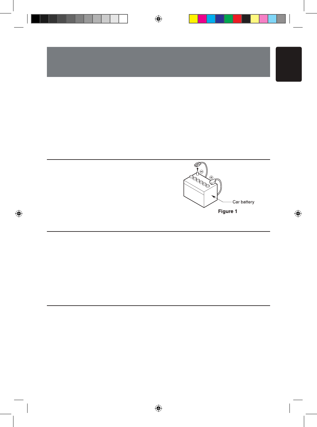
1. Before Starting
1. This set is exclusively for use in cars with a
negative ground 12V power supply.
2. Read these instructions carefully.
3. Be sure to disconnect the battery“ ”terminal
before starting. This is to prevent short circuits
during installation. (Figure 1)
2. Package Contents
3. General Cautions
1. Do not open the case. There are no
user- serviceable parts inside. If you
drop anything into the unit during
installation, consult your dealer or an
authorized Clarion service center.
2. Use a soft, dry cloth to clean the case.
Never use a rough cloth, thinner,
benzine, or alcohol etc. For tough dirt,
apply a little cold or warm water to a soft
cloth and wipe off the dirt gently.
Main unit .................................... 1
GPS antenna ............................. 1
SMK wiring harness .................. 1
AV cable .................................... 1
USB extending cable ................. 1
Remote control unit ................... 1
Battery (CR2025) ...................... 1
(Installed in remote control)
2DIN Trim ring ........................... 1
2DIN trim ring 200mm wide ....... 1
Back Strap ................................. 1
Flush mount bolts ..................... 4
Cap bolts ................................... 4
Rear radio stud and stopper ..... 1
Cleaning cloth ............................ 1
Warranty Card ........................... 1
CONTENTS
1. BEFORE STARTING .......................................................... 47
2. PACKAGE CONTENTS ...................................................... 47
3. GENERAL CAUTIONS ....................................................... 47
4. CAUTIONS ON INSTALLATION ......................................... 48
5. INSTALLING THE MAIN UNIT ............................................ 49
6. CAUTIONS ON WIRING ..................................................... 51
7. WIRE CONNECTIONS ....................................................... 52
NX_NZ500 0608.findd 47 6/16/2009 8:06:23 AM
English
NX500/NZ50048
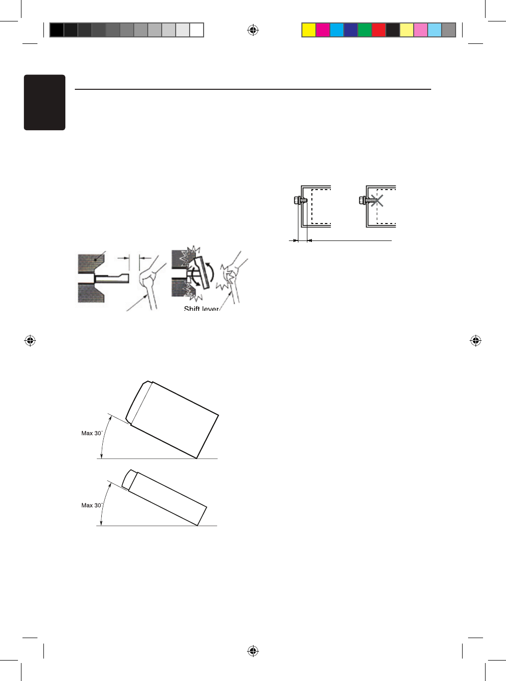
4. Cautions on Installation
1. Prepare all articles necessary for
installing the source unit before starting.
2. This model features an operation panel
that slides forward.
On some types of cars, the operation
panel may make contact with the
dashboard or gearshift lever, in which
cause it cannot be installed. Before
installing, check that the unit will not
hamper operation of the gearshift lever
or obstruct your view before selecting
the installation location. (Figure 2)
3. Install the unit within 30° of the
horizontal plane. (Figure 3)
4. If you have to do any work on the car
body, such as drilling holes, consult your
car dealer before hand.
5. Use the enclosed screws for installation.
Using other screws can cause damage.
(Figure 4)
Shift lever
Chassis Chassis
Damage
Max. 8 mm (M5 screw)
NZ409
Figure 2
Gearshift lever
(Check that it does not touch the LCD)
Dashboard
NX500
NZ500
Figure 3
Figure 4
NX_NZ500 0608.findd 48 6/16/2009 8:06:23 AM
English
NX500/NZ500 49
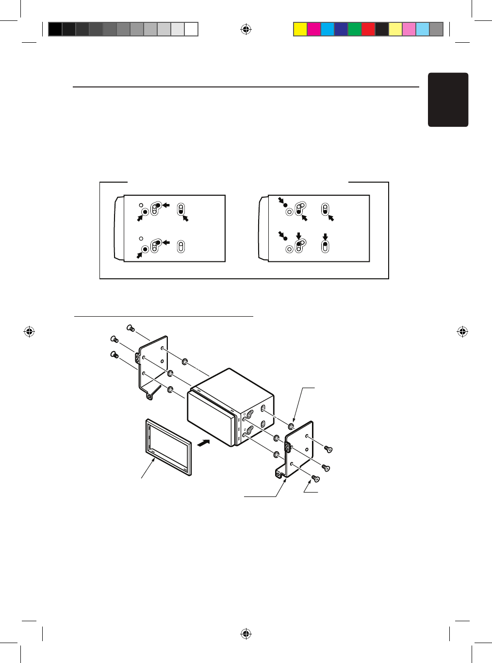
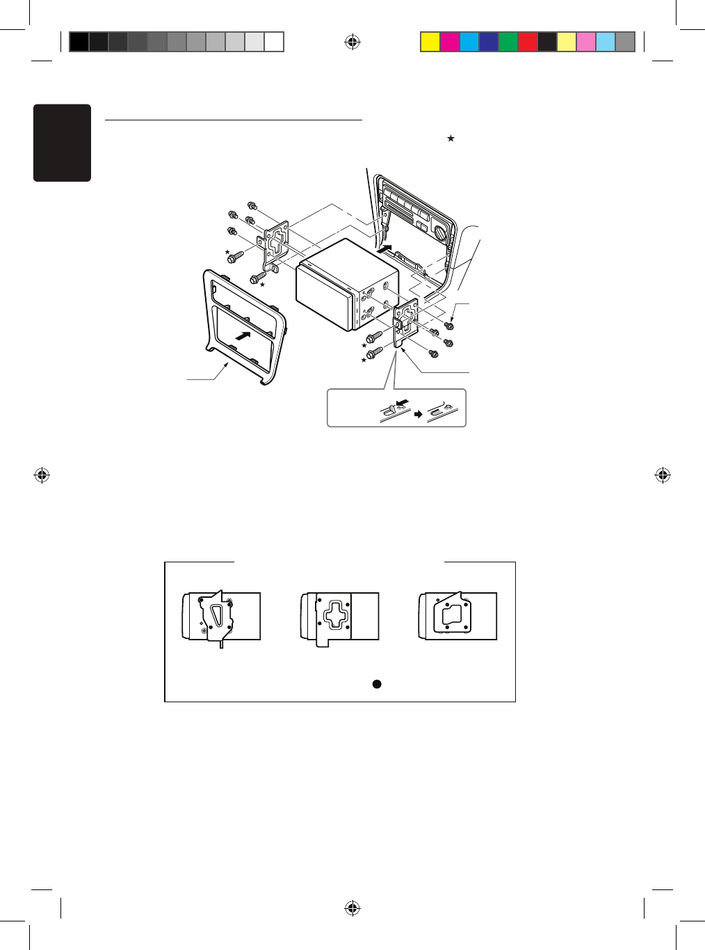
5. Installing the Main Unit
For NISSAN vehicle For TOYOTA vehicle
Mounting Screw Holes (Side View of the Main Unit)
6-Flat head screw
(M5 8)
(attached to the main unit)
6-Spacer (thickness: 1 mm)
Finisher (*1
)
Main Unit
Mounting bracket
(1 pair for the left and right sides)
This unit is designed for fixed installation in the
dashboard.
1. When installing the main unit in NISSAN
vehicles, use the parts attached to the unit
and follow the instructions in Figure 6.
When installing the main unit in TOYOTA
vehicles, use the parts attached to the vehicle
and follow the instructions in Figure 7.
2. Wire as shown in Section 7.
3. Reassemble and secure the unit in the
dashboard and set the face panel and center
panel.
Figure 6
Figure 5
Installing the Main Unit in NISSAN Vehicle
Note:
*1: Position the face panel with its wide edge at the
bottom. Fit the edge into the groove of the main
6- Spacer (thickness: 1mm)
6- Flat head screws
(M5x8)
(Attached to the main unit)
NX_NZ500 0608.findd 49 6/16/2009 8:06:23 AM
English
NX500/NZ50050
Installing the Main Unit in TOYOTA Vehicle
Install by using parts attached to the vehicle. (Screws marked are attached to the
vehicle.)
*2 Some panel openings are too small for the
unit depending on the vehicle type and
model. In such a case, trim the upper and
lower sides of the panel frame by about
0.5 to 1.5 mm so the unit can be inserted
smoothly.
*3 If a hook on the installation bracket interferes
with the unit, bend and flatten it with a nipper
or similar tool.
* 3
Figure 7
Main Unit
8-Hexagonal screw
(M5 8)
Mounting bracket
(1 pair for the left
and right sides)
Center Panel
(* 2 )
8- Hexagonal screws
(M5x8)
Figure 7
Mounting bracket
(1 pair for the left
and right sides)
Vehicles other than NISSAN and TOYOTA
In some cases the center panel may require modification. (Trimming, filing, etc.)
• Removing the Main Unit
When the main unit is to be removed, disassemble it in the reverse of the order in
“INSTALLING THE MAIN UNIT”.
3elpmaxE1elpmaxE Example 2
Affix the screws to the marks.
Typical Mounting Brackets
NX_NZ500 0608.findd 50 6/16/2009 8:06:24 AM
English
NX500/NZ500 51
6. Cautions on Wiring
1. Be sure to turn the power off before wiring.
2. Be particularly careful where you route the wires.
Keep them well away from the engine, and
exhaust pipe, etc. Heat may damage the wires.
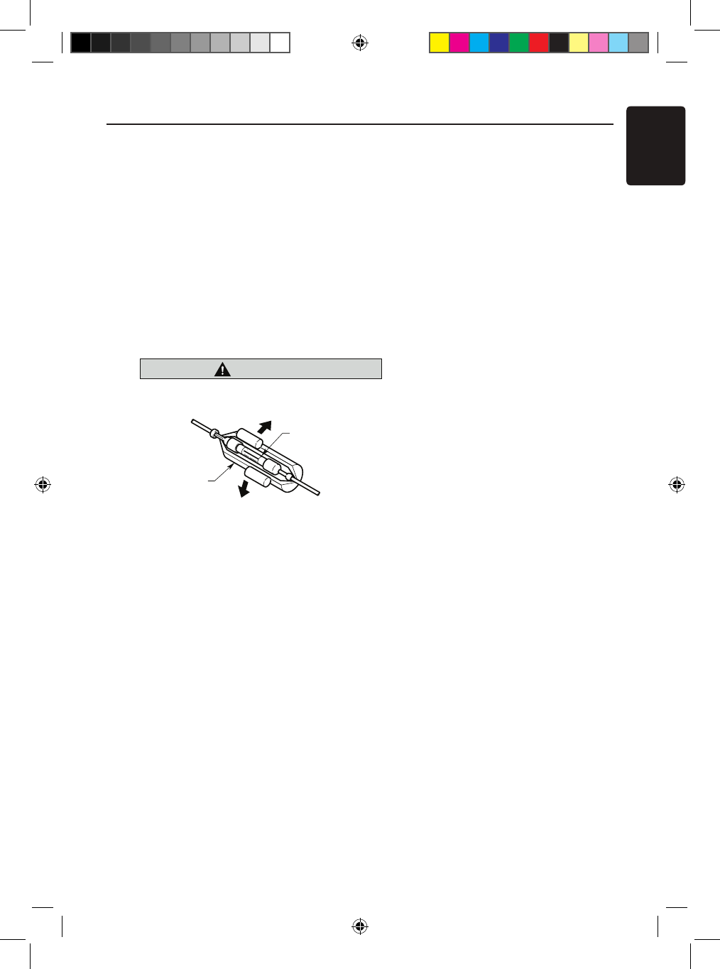
3. If the fuse should blow, check to see if the
wiring is correct.
If a fuse is blown, replace it with a new one of
the same amperage rating as the original (15A FUSE).
4. To replace the fuse, remove the old fuse on the back
of the unit and insert the new one. (Figure 8)
NOTE:
There are various types of fuse holder. Do not let the battery
side touch other metal parts.
CAUTION
caution
After the connection, fix the cord by a clamp
or insulation tape for protection.
Fuse (15A FUSE)
Fuse holder
Figure 8
Figure 8
NX_NZ500 0608.findd 51 6/16/2009 8:06:24 AM
English
NX500/NZ50052
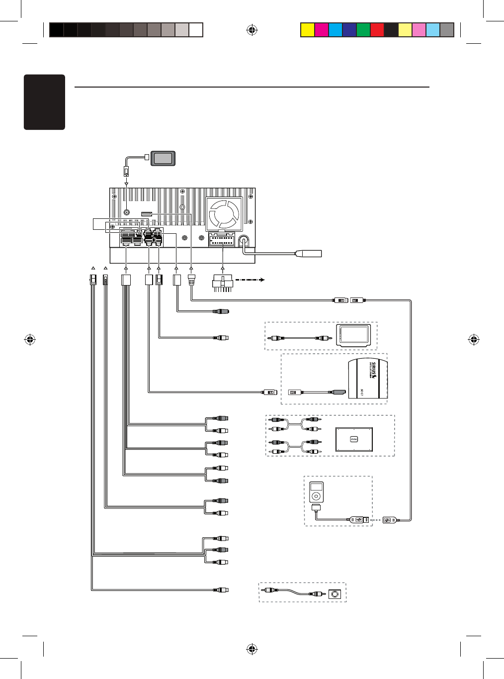
iPod
4-Channel Amplifier
Subwoofer 1
Subwoofer 2
BTL370/R
BTL370/L
Line Out
Rear R
Line Out
Rear L
Line Out
Front R
Line Out
Front L
Purple
Blue
Red
Black
Gray
Black
White
Red
White
Steering Wheel
Remote Control Terminal
Yellow
Monitor
Yellow
Connector
Cable
Sirius
SIRIUS CONNECT VEHICLE TUNER
Yellow
White
Red
Radio Antenna Jack
GPS
White
Red
Red
Red
White
Gray
Black
Black
Black
Camera
7. Wire Connections
Note:
•Before installing, be sure to disconnect the negative cable of the car battery.
•In the optional devices, the RCA cables and the Connector cables are separately-sold
items.
NX409
Refer to
page 54
iPod/iPhone
NX_NZ500 0608.indd 52 6/16/2009 8:06:25 AM
Video Out
Visual IN
English
NX500/NZ500 53
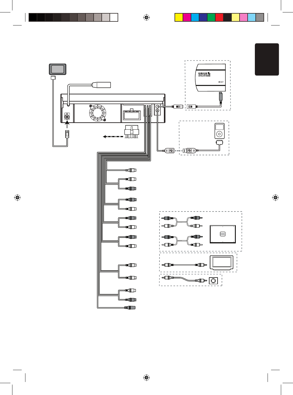
NZ409
Radio Antenna Jack
4-Channel Amplifier
Line Out
Subwoofer
Line Out
Rear R
Line Out
Rear L
Line Out
Front R
Line Out
Video Out
Front L
Visual IN
Audio/R
Audio/L
Camera
Yellow
White
White
Red
Red
Red
White
Yellow
Purple
Gray
Red
Black
Black
Black
Black
White
Connector
Cable
BTL370 /L
BTL370 /R
Blue
Steering Wheel
Remote Control Terminal
Sirius
Yellow
SIRIUS CONNECT VEHICLE TUNER
GPS
Monitor
iPod
Red
White
Red
Refer to
page 54
iPod/iPhone
NX_NZ500 0608.indd 53 6/16/2009 8:06:26 AM
English
NX500/NZ50054
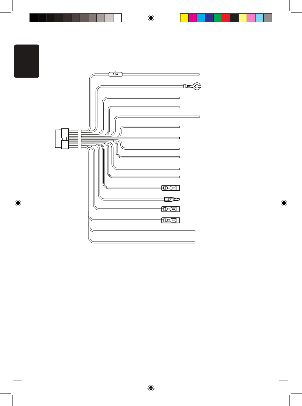
Note
:
*1: Connecting the PHONE INTERRUPT terminal
The phone interrupt will mute the audio if the lead receives a negative or ground signal.
Yellow
Black
Purple
Purple/Black
Grass-green
Gray
Gray/Black
White
White/Black
Green
Green/Black
Blue/White
Orange/White
Red
Brown
Blue
+12V main power
Ground
Rear right +
Rear right -
Parking brake cord
Front right +
Front right -
Front left +
Front left -
Rear left +
Rear left -
Amplifier turn-on cord
Illumination
+12V accessory
Phone interrupt (*1)
Auto antenna
See next page for how to connect the parking brake cord.
Violet/White Reverse
NX_NZ500 0608.indd 54 6/16/2009 8:06:26 AM
English
NX500/NZ500 55
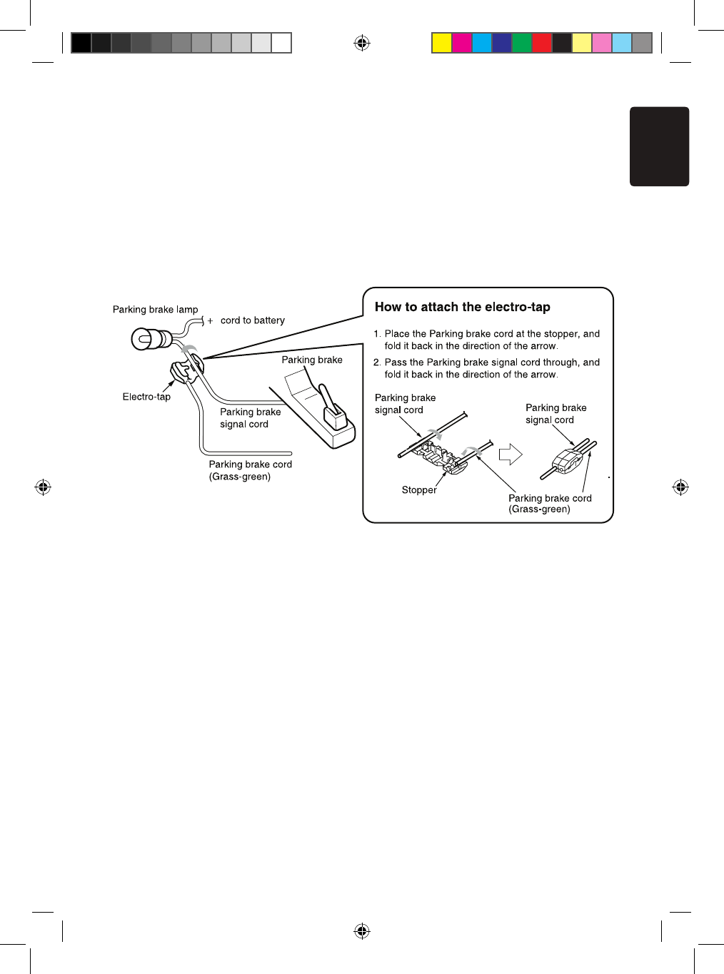
Connecting the parking brake cord
Connect the cord to parking brake lamp ground in the meter panel.
Note:
• Connecting the parking brake cord to lamp ground allows you to watch iPod/iPhone
video/DVD video/AV input when the parking brake is engaged.
• When the parking brake cord is not connected, the monitor will not show any video
sources.
• If “AUDIO ONLY” appears on the screen just after turning on the ACC power of the car,
release the parking brake while confirming safety, and then engage the parking brake
again.
Connecting the accessories
• Connecting to the external amplifier
The external amplifiers can be connected to the 6 channel RCA output connections.
Ensure that the connectors are not grounded or shorted to prevent damage to the unit.
• Connecting to iPod/iPhone device
The iPod/iPhone device can be connected to dedicated iPod/iPhone connection on the
main unit. For detailed information, refer to the instruction sheet or manual for the
iPod/iPhone cable.
Note:
• This unit may not support all functions of all iPod/iPhone devices
• The iPod/ iPhone connection will charge your iPod/iPhone unless the iPod/iPhone
battery is completely depleted.
If the specified cord of the cellular phone is connected to the phone interrupt cord of the
main unit, the audio mute is activated when cellular phone in use.
• Connecting to Sirius Satellite Radio Receiver
When Sirius Satellite Radio Receiver is to be connected, use the dedicated connector.
For detailed information,refer to the instruction manual of the Sirius Satellite Radio
Receiver.
NX_NZ500 0608.findd 55 6/16/2009 8:06:26 AM