SkyRC Technology Q200 AC/DC Quattro Charger User Manual
SKYRC Technology Co., Ltd. AC/DC Quattro Charger
User Manual
SkyRC Technology Co., Ltd. 2016 Version 1.0
AC/DC Quattro Charger
Q200Q200

TABLE OF CONTENTS
INTRODUCTION
SPECIAL FEATURES
WARNING AND SAFETY NOTES
PROGRAM FLOW CHART
OPERATION
OPERATING PROGRAM
CHARGING PROGRAM
BATTERY MEMORY SET AND CALL OUT
SYSTEM SETTING
BATTERY METER
BATTERY RESISTANCE METER
WARNING AND ERROR MESSAGE
USING THE CHARGE CONTROL SOFTWARE “CHARGE MASTER”
SPECIFICATION
CONFORMITY DECLARATION
COMMONLY USED TERMS
WARRANTY AND SERVICE
01
03
06
09
10
11
16
17
19
21
22
23
24
25
26
27
28

Congratulations on your choice of SKYRC Q200 AC/DC Quattro Balance
Charger/Discharger. This unit is simple to use, but the operation of a
sophisticated automatic charger such as SKYRC Q200 does require some
knowledge on the part of the user. These operating instructions are designed to
ensure that you quickly become familiar with its functions. It is therefore
important that you read right through the Operating Instructions, Warning and
Safety Notes before you attempt to use your new charger for the first time. We
hope you have many years of pleasure and success with your new battery
charger.
SKYRC Q200 is a four-channel charger with four independent circuits which
can charge four different kinds of batteries simultaneously, equipping with
480*320 colorful LCD display. Each two channels support power distribution in
AC model to make full use of the power when charging a small battery in one
channel and allocate all remaining power to charge another big battery pack.
What’s more, users could set the terminal voltage by themselves and connect it
to PC for PC control and firmware upgrade. Besides that, users could also use
it as Lithium Battery Meter and Battery Internal Resistance Meter. There are
Automatic Charging Current Limit, Capacity Limit, Temperature Threshold and
Processing Time Limit which makes the charger safe to use.
SKYRC Q200 is a high-performance, micro processor control charge/discharge
station with battery management suitable for use with all current battery types,
with integral equalizer for six-cell Lithium-Polymer (LiPo), Lithium iron
phosphate(LiFe) and Lithium-Ion (LiIon) batteries; maximum 10A charge
current and maximum 100W charge power. The additional LiHV mode is able to
charge the new generation of LiPo batteries with an end of charge voltage
4.35V.
Please BE SURE to read these INSTRUCTIONS, WARNING and SAFETY
NOTES before you use the charger for the first time.
It can be dangerous to mis-handle batteries and battery chargers, as there is
always a risk of batteries catching fire and exploding.
INTRODUCTION
01 ·
Q200
INTRODUCTION
· 02 Q200
Please read this entire operating manual completely and attentively
before using this product, as it covers a wide range of information on
operating and safety. Or please do use this product in company with a
specialist!
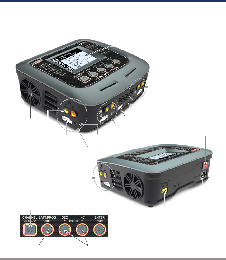
Switch from
Channel A to D or
Channel D to A
AC Input
100-240V
DC Input 11-18V
Power
Switch
Resume or Start Charge
Processes
Alter Values
See the Status of Individual
Cells in Balance Charge Mode
Scroll Through the Main Menu
Stop Any Charge Processes
Cooling Fan
LCD Display
USB Port
Micro USB Port for
PC Link
Output Socket
4mm Banana Plug
Balance
Lead Socket
Temperature
Sensor Port
Channel B
Channel C
Channel D
Channel A
03 ·
Q200
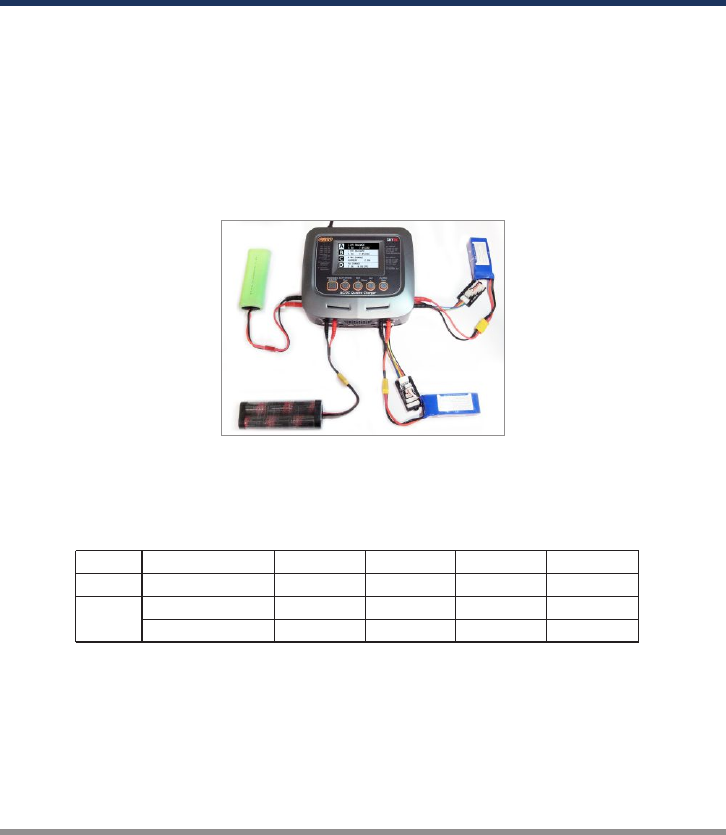
Four-channel Charger
SKYRC Q200 allows you to plug 4 batteries into one charger simultaneously, and it will
intelligently and automatically charge 4 battries at once to their maximum capacity. To top
of it, the batteries being charged do not even need to have the same configuration. You
can connect different chemistry(NiMH/NiCd/LiPo/LiFe/Lilon/LiHV/Pb)batteries into any of
the charging channels.
Dual Input and Power Distribution
The input of SKYRC Q200 is AC 100-240V and DC 11-18V.
In AC mode, it supports power distribution.
Please refer to below table for detailed distributed power value in different channels.
SPECIAL FEATURES
Colorful LCD Display
It is equipped with 480*320 3.5" colorful LCD display. The user interface looks clear,
visible and comfortable.
CH A CH B CH C CH D
DC Mode
Charging Power 0-100W 0-100W 0-50W 0-50W
AC Mode
Charging Power 50-100W 50-100W 0-50W 0-50W
Power Distribution A+C=100W B+D=100W A+C=100W B+D=100W
Optimized Operating Software
SKYRC Q200 features the so-called AUTO function that set the feeding current during the
process of charging or discharging. Especially for lithium batteries, it can prevent the
overcharging which may lead to an explosion due to the user's fault. It can disconnect the
circuit automatically and alarm once detecting any malfunction. All the programs of this
product were controlled through two way linkage and communication, to achieve the
maximum safety and minimize the trouble. All the settings can be configured by users!

SPECIAL FEATURES
· 04 Q200
Internal Independent Lithium Battery Balancer
SKYRC Q200 employs an individual-cell-voltage balancer. It isn't necessary to connect
an external balancer for balance charging.
Balancing Individual Cells Battery Discharging
During the process of discharging, SKYRC Q200 can monitor and balance each cell of
the battery individually. Error message will be indicated and the process will be ended
automatically if the voltage of any single one cell is abnormal.
Adaptable to Various Type of Lithium Battery
SKYRC Q200 is adaptable to various types of lithium batteries, such as LiPo, LiIon and
the new LiFe series of batteries.
LiHV Mode Available
The additional LiHV mode is able to charge the new generation of LiPo batteries with an
end of charge voltage 4.35 V.
Smart Phone Control via Bluetooth (both iOS and Android)
Finally, your charger gets its own apps. Bluetooth Module is inside of the charger and you
could control your charger by your smart phone after they are connected via bluetooth.
Battery Memory (Data Store/Load)
The charger can store up to 40 different charge/discharge profiles for each channel. You
can keep the data pertaining to program setting of the battery of continuous charging or
discharging. Users can call out these data at any time without any special program
setting.
Terminal Voltage Control(TVC)
The charger allows user to change the end voltage. (for expert user only)
PC Control Software “Charge Master”
The free “Charge Master” software gives you unparalleled ability to operate the charger
through the computer. You can monitor pack voltage, cell voltage and other data during
the charging, view charge date in real-time graphs. And you can initiate, control charging
and update firmware from “Charge Master”.
With “Charger Master” and one computer, you could operate and update two channels
simultaneously.
Charge/Discharge Indication
There is a clear icon when the charger is in process to indicate and charge or discharge
status and the current capacity percentage.

Automatic Charging Current Limit
You can set up the upper limit of the charging current when charging your NiMH or NiCd
battery, it is useful for the NiMH battery of low impedance and capacity in the 'AUTO'
charging mode.
Capacity Limit
The charging capacity is always calculated as the charging current multiplied by time. If
the charging capacity exceeds the limit, the process will be terminated automatically
when you set the maximum value.
Temperature Threshold*
The battery's internal chemical reaction will cause the temperature of the battery to rise.
If the temperature limit is reached, the process will be terminated.
This function is available by connecting optional temperature probe, which is not included in the package.
*
Processing Time Limit:
You can also limit the maximum process time to avoid any possible defect.
Battery Internal Resistance Meter
The user can check battery's total internal resistance and each cell's internal resistance.
LiPo Battery Meter
The user can check battery's total voltage, the highest voltage, the lowest voltage and
each cell's voltage.
SPECIAL FEATURES
05 ·
Q200
Re-Peak Mode of NiMH/NiCd Battery
In re-peak charge mode, the charger can peak charge the battery once, twice or three
times in a row automatically. This is good for making certain the battery is fully charged.
Delta-peak Sensitivity for NiMH/NiCd
Delta-peak sensitivity for NiMH/NiCd battery: The automatic charge termination program
based on the principle of the Delta-peak voltage detection. When the battery's voltage
exceeds the threshold, the process will be terminated automatically.
Cyclic Charging/Discharging
1 to 5 cyclic and continuous process of charge > discharge or discharge > charge is
operable for battery refreshing and balancing to stimulate the battery's activity.
Fast and Storage Mode of Lithium Battery
Purposes to charge lithium battery varies, 'fast' charge reduce the duration of charging,
whereas 'store' state can control the final voltage of your battery, so as to store for a long
time and protect useful time of the battery.
These warnings and safety notes are particularly important. Please follow the
instructions for maximum safety; otherwise the charger and the battery can be
damaged or at worst it can cause a fire.
Never leave the charger unattended when it is connected to its power supply. If any
malfunction is found, TERMINATE THE PROCESS AT ONCE and refer to the
operation manual.
Keep the charger well away from dust, damp, rain, heat, direct sunshine and vibration.
Never drop it.
The allowable DC input voltage is 11~18V DC
This charger and the battery should be put on a heat-resistant, noninflammable and
nonconductive surface. Never place them on a car seat, carpet or similar. Keep all
the inflammable volatile materials away from operating area.
Make sure you know the specifications of the battery to be charged or discharged to
ensure it meets the requirements of this charger. If the program is set up incorrectly,
the battery and charger may be damaged .It can cause fire or explosion due to
overcharging.
Be very careful to choose the correct voltage for different types of battery otherwise you
may cause damage to the batteries. Incorrect settings could cause the cells to fire or
explode.
WARNING AND SAFETY NOTES
The allowable AC input voltage is 100~240V AC
· 06 Q200
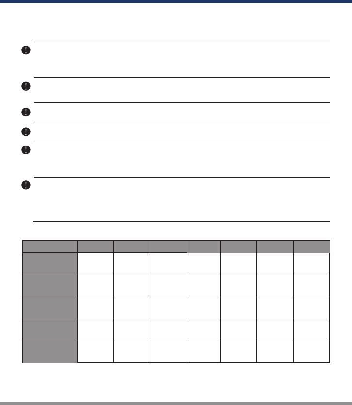
Standard Battery Parameters
3.7V/cell
Nominal
Voltage
Min. Discharge
Voltage
Max Charge
Voltage
Storage
Voltage
Allowable
Fast Charge
3.7V/cell
4.2V/cell
3.8V/cell
≦1C
LiPo LiIon
3.6V/cell
4.1V/cell
≦1C
3.3V/cell
3.6V/cell
3.3V/cell
≦4C
LiFe
3.0-3.3V/cell 2.9-3.2V/cell 2.6-2.9V/cell
1.2V/cell
1.5V/cell
n/a
1C-2C
NiCd
1.2V/cell
1.5V/cell
n/a
1C-2C
MiMH
2.0V/cell
2.46V/cell
n/a
≦0.4C
Pb
0.1-1.1V/cell 0.1-1.1V/cell
1.8V/cell
LiHV
3.7V/cell
4.35V/cell
3.85V/cell
≦1C
3.1-3.4V/cell

A battery pack which consists of different types of cells (including different
manufacturers)
A battery that is already fully charged or just slightly discharged.
Non-rechargeable batteries (Explosion hazard).
Batteries that require a different charge technique from NiCd, NiMh, LiPo or Gel cell
(Pb, Lead acid).
A faulty or damaged battery.
A battery fitted with an integral charge circuit or a protection circuit.
Batteries installed in a device or which are electrically linked to other components.
Batteries that are not expressly stated by the manufacturer to be suitable for the
currents the charger delivers during the charge process.
Please bear in mind the following points before commencing charging:
Did you select the appropriate program suitable for the type of battery you are
charging?
Did you set up adequate current for charging or discharging?
Have you checked the battery voltage? Lithium battery packs can be wired in parallel
and in series, i.e. a 2 cell pack can be 3.7V (in parallel) or 7.4V (in series).
Have you checked that all connections are firm and secure?
Make sure there are no intermittent contacts at any point in the circuit.
Charging
During charge process, a specific quantity of electrical energy is fed into the battery. The
charge quantity is calculated by multiplying charge current by charge time. The maximum
permissible charge current varies depending on the battery type or its performance, and
can be found in the information by the battery manufacturer. Only batteries that are
expressly stated to be capable of quick-charge are allowed to be charged at rates higher
than the standard charge current.
Connect the battery to the terminal of the charger: red is positive and black is negative.
Due to the difference between resistance of cable and connector, the
charger can not detect resistance of the battery pack, the essential requirement
for the charger to work properly is that the charge lead should be of adequate conductor
cr os s- se ction , an d hi gh qual it y co nn ec tors wh ic h ar e no rm al ly g ol d-
plated should be fitted to both ends.
Always refer to the manual by battery manufacturer about charging methods,
recommended charging current and charging time. Especially, the lithium battery should be
charged according the charging instruction provided by the manufacturer strictly.
Attention should be paid to the connection of lithium battery especially.
Do not attempt to disassemble the battery pack arbitrarily.
Never attempt to charge or discharge the following types of batteries.
WARNING AND SAFETY NOTES
07 ·
Q200

Discharging
The main purpose of discharging is to clean residual capacity of the battery, or to reduce
the battery voltage to a defined level. The same attention should be paid to the discharging
process as charging. The final discharge voltage should be set up correctly to avoid deep-
discharging. Lithium battery can not be discharged to lower than the minimum voltage, or it
will cause a rapid loss of capacity or a total failure. Generally, lithium battery doesn't need
to be discharged. Please pay attention to the minimum voltage of lithium battery to protect
the battery.
Some rechargeable batteries have a memory effect. If they are partly used and recharged
before the whole charge is accomplished, they remember this and will only use that part of
their capacity next time. This is a memory effect. It is said that NiCd and NiMH batteries
are suffering from memory effect. NiCd has more memory effect than NiMH.
Please get highlighted that lithium battery packs can be wired in parallel and in series. In
the parallel connection, the battery s capacity is calculated by multiplying single battery
capacity by the number of cells with total voltage stay the same. The voltages imbalance
may cause fire or explosion .Lithium battery is recommended to charge in series.
WARNING AND SAFETY NOTES
· 08 Q200
This device complies with part 15 of the FCC Rules. Operation is subject to the following two
conditions: (1) This device may not cause harmful interference, and (2) this device must accept
any interference received, including interference that may cause undesired operation.
Any Changes or modifications not expressly approved by the party responsible for compliance
could void the user's authority to operate the equipment.
This equipment has been tested and found to comply with the limits for a Class B digital device,
pursuant to part 15 of the FCC Rules. These limits are designed to provide reasonable protection
against harmful interference in a residential installation. This equipment generates uses and can
radiate radio frequency energy and, if not installed and used in accordance with the instructions,
may cause harmful interference to radio communications. However, there is no guarantee that
interference will not occur in a particular installation. If this equipment does cause harmful
interference to radio or television reception, which can be determined by turning the equipment off
and on, the user is encouraged to try to correct the interference by one or more of the following
measures:
-Reorient or relocate the receiving antenna.
-Increase the separation between the equipment and receiver.
-Connect the equipment into an outlet on a circuit different from that to which the receiver is
connected.
-Consult the dealer or an experienced radio/TV technician for help.
FCC Caution:

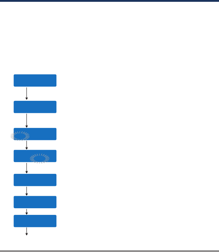
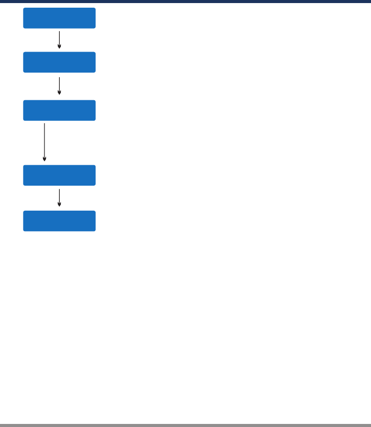
PROGRAM FLOW CHART
BATT/PROGRAM
Pb BATT
ENTER
START
Pb CHARGE
2.0A 2.0V (1P) DEC
INC Pb DISCHARGE
0.1A 2.0V (1P)
BATT/PROGRAM
NiCd BATT
NiCd CHARGE
CURRENT 2.0A
ENTER
START
DEC
INC NiCd DISCHARGE
0.1A CUT: 1.0V DEC
INC NiCd CYCLE
CHG>DCHG 1
BATT/PROGRAM
NiMH BATT
ENTER
START
NiMH CHARGE
CURRENT 2.0A DEC
INC NiMH DISCHARGE
0.1A CUT: 1.0V
NiMH CYCLE
CHG>DCHG 1
DEC
INC
BATT/PROGRAM
LiPo BATT
LiPo BALANCE CHG
2.0A 7.4V (2S)
LiPo CHARGE
2.0A 7.4V (2S)
LiPo FAST CHARGE
2.0A 7.4V (2S)
LiPo STORAGE
2.0A 7.4V (2S)
LiPo DISCHARGE
2.0A 7.4V (2S)
ENTER
START
DEC
INC
DEC
INC
DEC
INC
DEC
INC
DECINC
DECINC
BATT/PROGRAM
LiFe BATT
Lilo BALANCE CHG
2.0A 7.2V (2S)
Lilo CHARGE
2.0A 7.2V (2S)
Lilo FAST CHARGE
2.0A 7.2V (2S)
Lilo STORAGE
2.0A 7.2V (2S)
Lilo DISCHARGE
2.0A 7.2V (2S)
ENTER
START
DEC
INC
DEC
INC
DEC
INC
DEC
INC
BATT/PROGRAM
LiIo BATT
LiFe BALANCE CHG
2.0A 6.6V (2S)
LiFe CHARGE
2.0A 6.6V (2S)
LiFe FAST CHARGE
2.0A 6.6V (2S)
LiFe STORAGE
2.0A 6.6V (2S)
LiFe DISCHARGE
2.0A 6.6V (2S)
ENTER
START
DEC
INC
DEC
INC
DEC
INC
DEC
INC
DECINC
BATT/PROGRAM
BATT METER
4.20 4.19 4.19 V
0.00 0.00 0.00 V
MAIN 0.00V
H0.000V L0.000V
DEC
INC
DECINC
DECINC
DEC
INC
NiCd RE-PEAK
1
DEC
INC
NiMH RE-PEAK
1
DEC
INC
NiMH Auto CHARGE
CURRENT 2.0A
DEC
INC
NiCd Auto CHARGE
CURRENT 2.0A
DECINC
DECINC
DECINC
LiHV BALANCE CHG
2.0A 7.6V (2S)
LiHV CHARGE
2.0A 7.6V (2S)
LiHV FAST CHARGE
2.0A 7.6V (2S)
LiHV STORAGE
2.0A 7.6V (2S)
LiHV DISCHARGE
2.0A 7.6V (2S)
BATT/PROGRAM
LiHV BATT
ENTER
START
DEC
INC
DEC
INC
DEC
INC
DEC
INC
DECINC
Note: The flow chart is taking one channel for example as the flow chart for the two channels (Channel A, B, C
and Channel D) are identical.
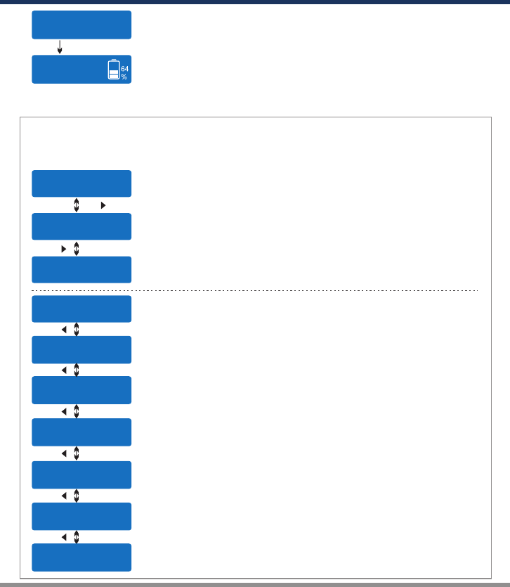
BATT/PROGRAM
BATT MEMORY
ENTER
START
[ BATT MEMORY 1 ]
ENTER SET->
ENTER
START
BATT TYPE
LiPo DEC
INC BATT VOLTS
7.4V ( 2S ) DEC
INC CHARGE CURRENT
4.9A DEC
INC DSCH CURRENT
2.2A
DSCH VOLTAGE
3.0V/CELL
TVC=YOUR RISK
4.20V
DEC
INC
ENTER
START
ENTER
START
BATT/PROGRAM
SYSTEM SETTING->
ENTER
START
Stop
Batt Type
DECINC
SAVE PROGRAM
ENTER
SAVE PROGRAM
SAVE….
[ BATT MEMORY 1 ]
LiPo 7.4V (2S )
[ BATT MEMORY 1 ]
C:4.9A D:2.2A
ENTER CHARGER
LOAD……
LiPo BALANCE CHG
4.9A 7.4V(2S)
LiPo CHARGE
4.9A 7.4V(2S)
DEC
INC LiPo FAST CHARGE
4.9A 7.4V(2S)
DEC
INC LiPo STORAGE
4.9A 7.4V(2S)
LiPo DISCHARGE
2.2A 7.4V(2S)
DEC
INC
DEC
INC
BATT TYPE
MiMH DEC
INC BATT VOLTS
2.4V (2S)
ENTER
START
CHARGE CURRENT
3.3A
DEC
INC
DEC
INC TRICKLE
100mA DEC
INC PEAK DELAY
1Min
DECINC
DSCH CURRENT
2.2A
DEC
INC DSCH VOLTAGE
1.1V/CELL
SAVE PROGRAM
ENTER
ENTER
START
BATT TYPE
Pb
BATT VOLTS
4.0V (2P)
DEC
INC CHARGE CURRENT
3.3A
DEC
INC DSCH CURRENT
1.5A
DEC
INC DSCH VOLTAGE
1.7V/CELL
DEC
INC
SAVE PROGRAM
ENTER
DECINC
DEC
INC
DEC
INC
DECINC
BATT/PROGRAM
BATT RESISTANCE
DECINC
ENTER
START
005 003 003 mΩ
005 mΩDEC
INC TATAL: 16mΩ
H: 5mΩ L: 3mΩ
ENTER
START
STARG/ENTER>3Seconds
SAVE PROGRAM
SAVE….
ENTER
START
[ BATT MEMORY 2 ]
NiMH 2.4V (2S )
[ BATT MEMORY 2 ]
C:1.0A D:1.0A
STARG/ENTER>3s
ENTER CHARGER
LOAD……
NiMH CHARGE
CURRENT 1.0A
NiMH Auto CHARGE
CURRENT 1.2A
DEC
INC
DEC
INC
DEC
INC
DEC
INC
NiMH DISCHARGE
1.0A CUT: 2.0V
NiMH RE-PEAK
2
NiMH CYCLE
DCHG>CHG 1
[ BATT MEMORY 2 ]
ENTER SET->
[ BATT MEMORY 3 ]
ENTER SET->
SAVE PROGRAM
SAVE….
ENTER
START
[ BATT MEMORY 3 ]
Pb 4.0V (2S )
[ BATT MEMORY 3 ]
C:3.3A D:1.5A
ENTER CHARGER
LOAD……
Pb CHARGE
3.3A 4.0V(2P)
Pb DISCHARGE
1.5A 4.0V(2P)
Rest Time
CHG>DCHG 10Min
DEC
INC
Safety Timer
ON 120Min DEC
INC
Capacity Cut-Off
ON 5000mAH DEC
INC
DECINC
DEC
INC
Temp Cut-Off
ON 50°C 122°F
NiMH Sensitivity
D.Peak 4mv
DEC
INC
NiCd Sensitivity
D.Peak 4mv
Key Beep ON
Buzzer ON
DEC
INC
DEC
INC
Version
HW:1.00 FW: 1.10
Load Factory Set
Enter DEC
INC DC Input Low
CUT-OFF 11.0V
ACMax Power Set
50W DEC
INC
Temperature Unit
Celsius
DEC
INC
ENTER
START
09 ·
Q200
START ENTER > 3s
Bal. Connection
ON
DECINC
OPERATION
When you are willing to alter the parameter value in the program, press the
START/ENTER button to make it blink then change the value by pressing DEC and INC
button. The value will be stored by re-pressing the START/ENTER button. If there is
another parameter can be altered in the same screen, when you confirm the first
parameter value, the next parameter value will start to blink which means it is ready to
alert.
When you are willing to start the process, press and hold the START/ENTER button for 3
seconds. When you are willing to stop the progress or go back to previous step/screen,
press the BATT PROG/STOP button once.
When you power on the charger, it will enter LiPo Battery balance program directly. You
could change the mode (balance mode, normal charge mode, fast charge mode, store
mode or discharge mode), enter the desired charging/discharging mode, set the referred
parameter and start the progress.
If you have no request for LiPo Battery program, please press the BATT PROG/STOP
button to enter BATT PROGRAM screen.
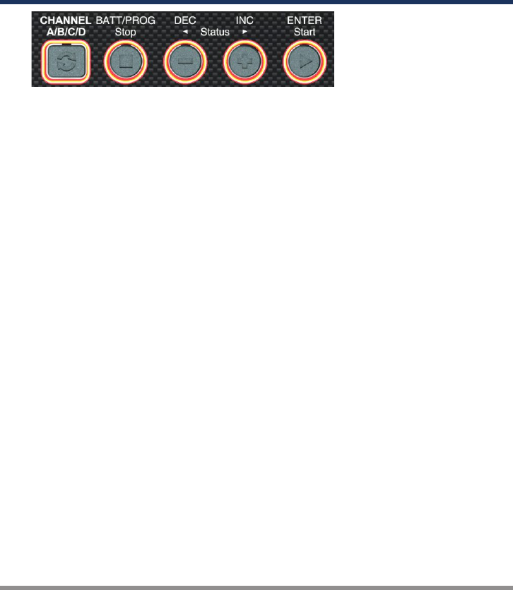
CHANNEL A/B/C/D
It is used to switch among channels.
BATT PROG / STOP Button:
It is used to stop the progress or go back to previous step/screen
DEC Button:
It is used to go through the menus and decrease the parameter value
INC Button:
It is used to go through the menus and increase the parameter value
ENTER / START Button:
It is used to enter parameter or store parameter on screen.
· 10 Q200
OPERATING PROGRAM
Here is the detailed procedure to make the charger work. All the screens and operations
will take Li-Po BALANCE CHARGE program for example,
Note: We will explain one channel as the operating procedure
of Channel A, B, C and D is identical.
1. Connection
Connecting to power source
There are two kinds of inputs for SKYRC Q200, DC 11-18V and AC 100-240V.
A. Operating in AC mode
SKYRC Q200 comes with built in switching power supply. You can connect the AC
power cord directly to the main AC socket. (100-240V AC).
1).
11 ·
Q200
In AC mode, it supports Power Distribution. You could set the AC Max Power for
one channel (Take Channel A for example)as following,
BATT/PROGRAM
SYSTEM SETTING->
LIPO BALANCE
2.0A 7.4V(2S)
A
B
LIPO BALANCE
2.0A 7.4V(2S)
C
LIPO BALANCE
2.0A 7.4V(2S)
D
LIPO BALANCE
2.0A 7.4V(2S)
A
B
LIPO BALANCE
2.0A 7.4V(2S)
C
LIPO BALANCE
2.0A 7.4V(2S)
D
Safety Timer
ON 120Min
LIPO BALANCE
2.0A 7.4V(2S)
A
B
LIPO BALANCE
2.0A 7.4V(2S)
C
LIPO BALANCE
2.0A 7.4V(2S)
D
AC Max Power Set
50W
LIPO BALANCE
2.0A 7.4V(2S)
A
B
C
LIPO BALANCE
2.0A 7.4V(2S)
D
AC Max Power Set
65W
AC Max Power Set
35W
And the other channel (Channel C) will take the rest power automatically (For example, if
you set channel A as AC 65W, the channel C will be AC 35W).
If Channel A and Channel C are both charging, you can’t change the AC power.
If Channel A is charging, you can change AC power of Channel C and Channel
A will take the rest power automatically.
NOTE1:
NOTE2:
B. Operating in DC mode
Please connect SKYRC Q200 with AC/DC power supply by supplied DC input cable. Also
you could use terminal clips with DC connectors, for attaching directly to 12V car
batteries. It is critically important that you use either a fully charged 13.8V car battery or a
high quality AC/DC power supply in the range of 11-18V DC output with minimum power
400W or higher to insure reliable performance.
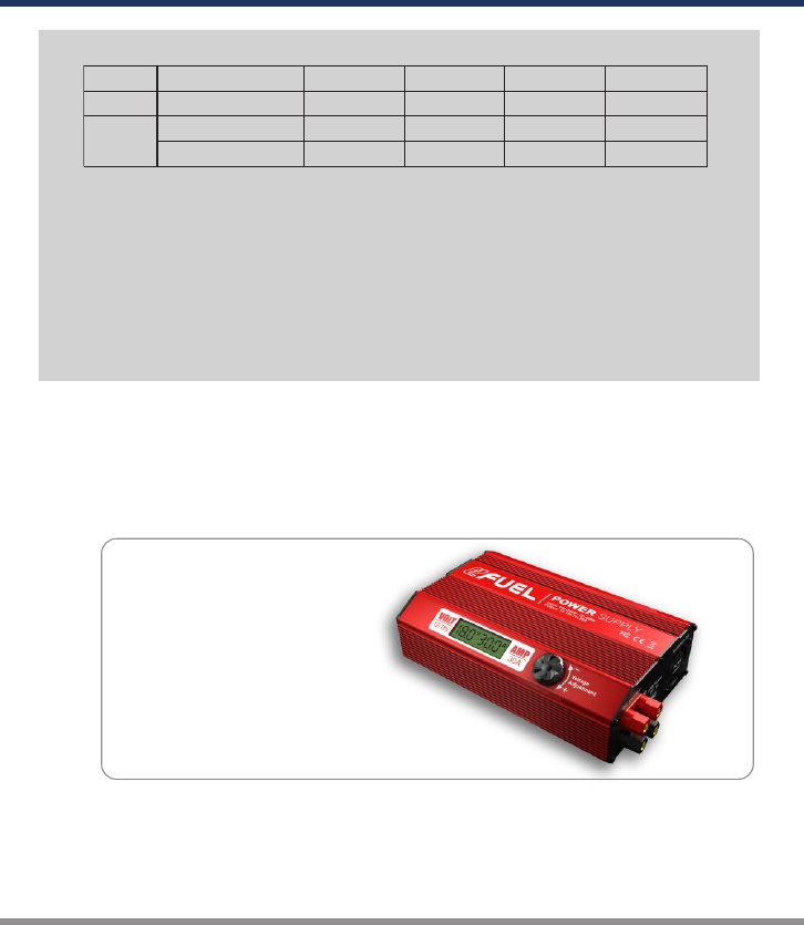
Please refer to below table for detailed distributed power value in different channels.
CH A CH B CH C CH D
DC Mode
Charging Power 0-100W 0-100W 0-50W 0-50W
AC Mode
Charging Power 50-100W 50-100W 0-50W 0-50W
Power Distribution A+C=100W B+D=100W A+C=100W B+D=100W
The total power of Channel A and Channel C is 100W; and the total power of
Channel B and Channel D is 100W.
Power distribution can be applied in certain two channels. Take Channel A for
example, it can be shared power with Channel C only, but can’t with Channel B or
Channel D.
There is min and max charging power limit in certain two channels. Take Channel
A and Channel C for example, Channel A can be set from 50W to 100W while
Channel C can be set from 0 to 50W.
Note 1:
Note 2:
Note 3:
Important Notice
Low quality DC power source may
damage your Q200 charger. We
recommend you to choose EFUEL
30A/540W Power Supply (SK-
200013).
· 12 Q200
OPERATING PROGRAM
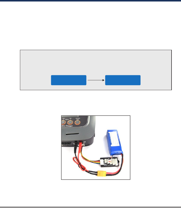
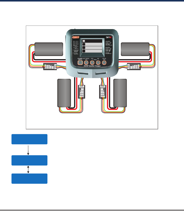
Failure to connect as shown in this diagram will damage this charger.
To avoid short circuit between the charge lead always connect the charge cable to the
charger first, then connect the battery. Reverse the sequence when disconnecting.
WARNING:
Connecting the battery
Important!!! Before connecting a battery it is absolutely essential to check one last
time that you have set the parameters correctly. If the settings are incorrect, the
battery may be damaged, and could even burst into flames or explode. To avoid
short circuits between the banana plugs, always connect the charge leads to the
charger first, and only then to the battery. Reverse the sequence when
disconnecting the pack.
Balance Socket
The balance wire attached to the battery must be connected to the charger with the
black wire aligned with the negative marking. Take care to maintain correct polarity!
(See the wiring diagram below.)
This diagram shows the correct way to connect your battery to the SKYRC Q200
while charging.
2).
3).
For safety issue, the default setting for charging Lithium(LiPo, Lilo, LiFe and LiHV)
battery is using balance adaptor to connect battery and charger in Charge, Fast
Charge, Balance Charge and Storage modes. But if the battery comes no balance
wire, you could disable this function in system settingasfollowing,
BATT/PROGRAM
SYSTEM SETTING
BAL.Connection
OFF
13 ·
Q200
OPERATING PROGRAM
OPERATING PROGRAM
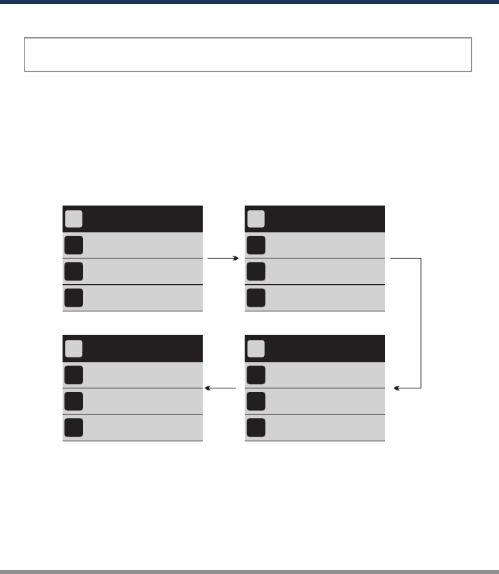
Locate the flowcharts show the entire programming menu. It is highly recommended to
have these flowcharts handy while learning to operate this charger.
There are two main ways in which to set the charger.
A memory profile is available for setting and storing pertinent information for up to
40 different batteries, each channel can store 10 sets. Once a battery's information
is stored into a memory it will be retained until changed again manually. Recalling a
battery's memory number makes the charger instantly ready to go!
If you do not wish to use the battery memories, this charger can be manually set
before each use.
2. Getting started
(1)
(2)
For following step, all are basing on manually set
3. BATT/PROGRAM Select
BATT/PROGRAM
LiPo BATT
4. Mode Select
6. Program Start
LiPo BALANCE CHG
2.0A 11.1V (3S)
Press INC and DEC to go through all the programs and press
START/ENTER to enter LiPo BATT Program.
5. Battery Setting
LiPo BALANCE CHG
2.0A 11.1V (3S) Press INC and DEC to go through all the modes and press
START/ENTER to enter LiPo Balance Charge Mode.
Press START/ENTER, the current value will start to blink, press
INC and DEC to change the value and press START/ENTER to
confirm your setting.
At the same time, the battery cells number will start to blink,
press INC and DEC to change the value and press
START/ENTER to confirm your setting.
LiPo BALANCE CHG
2.0A 11.1V (3S)
BATTERY CHECK
WAIT...
LiPo BALANCE CHG
2.0A 11.1V (3S) Press and hold START/ENTER for 3 seconds to start the
program.
The charger is detecting the battery cell.
R shows the number of cells detected by the charger and S is
the number of cells set by you at the previous screen. If both
numbers are not identical, press STOP to go back to previous
screen to recheck the number of cells of the battery pack before
going ahead.
R:3SER S:3SER
CANCEL(STOP)
START/ENTER
START/ENTER
START/ENTER
START/ENTER
START/ENTER
> 3 Seconds
· 14 Q200
OPERATING PROGRAM
R:3SER S:3SER
CONFIRM(ENTER)
Lp4s 1.5A 12.14V
BAL 000:50 00022
7. Charging Status Monitor
R shows the number of cells detected by the charger and S is the number
of cells set by you at the previous screen. If both numbers are identical,
press START/ENTER to start charging process.
During charge process, real-time status will be showed as left screen.
VARIOUS INFORMATION DURING THE PROCESS
Press INC or DEC during charging or discharging process, you can inquire various information on LCD
screen .
LP4s 1.5A 12.14V
BAL 000:50 00022
4.07 4.06 4.11 V
0.00 0.00 0.00 V
Fuel= 90%
Cell= 4.10V
INC
INC
LP4s 1.5A 12.14V
BAL 000:50 00022
Ext. Temp ----
Int. Temp 37°C
DEC
Temp Cut-Off
50C
DEC
Final voltage when the program ends.
Input voltage.
Safety timer ON and duration of time in minutes.
Capacity cut-off ON and the setting value of capacity.
Voltage of each cell in the battery pack when the battery is connected
with balance lead.
Internal temperature.
Temperature probe is needed to show external temperature.
Charged capacity percentage and average cell voltage of the battery
pack.
Real-time status: battery type, battery cell, charge current, battery
voltage, elapsed time and charged capacity
Cut off temperature
START/ENTER
DEC
DEC
DEC
DEC
End Voltage
12.6V(3S)
IN Power Voltage
12.56V
Safety Time
ON 200min
Capacity Cut-Off
ON 5000mAh
The battery icon indicates the charge / discharge status and finished
capacity percentage.
Green—charge Red—discharge
NOTE:
15 ·
Q200
OPERATING PROGRAM
8. Program Stop
9. Program Complete
During the charging process, press STOP to stop the charging process.
When the charging process finishes, an audible sound will be heard.
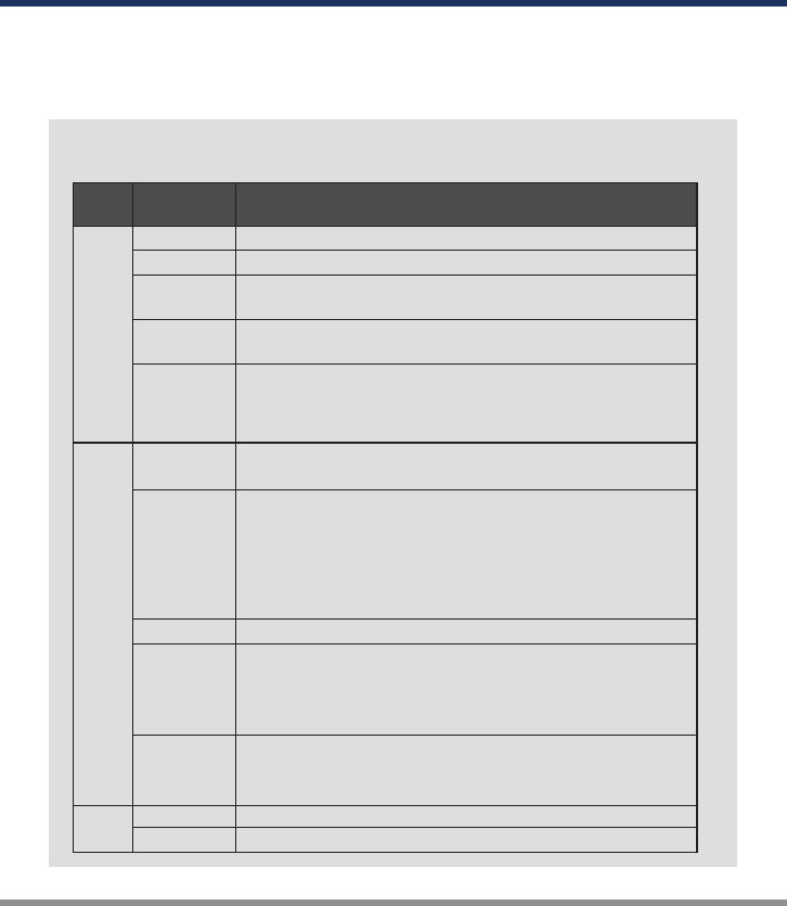
NiMH
NiCd RE-PEAK
CYCLE
Pb
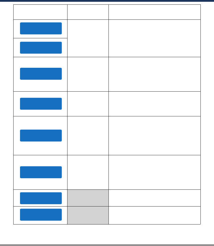
Batt
Type
Operation
Program Description
This charging mode is for charging LiPo/LiFe/LiIon/LiHV battery in normal mode.
This program is for charging or discharging LiPo/LiFe/LiIon/LiHV
battery which will not be used for long time.
The charging capacity may be less than normal charging but the
process time will be reduced.
This mode is for balancing the voltage of LiPo/LiFe/LiIon/LiHV battery
cells while charging.
The charger will charge NiMH and NiCd batteries using the
charge current set by the user.
In this program the charger detects the condition of the battery
which is connected to the output and automatically charges the
battery.
Note: you should set up the upper limit of the charge
current to avoid damage by excessive feeding current.
Some batteries of low resistance and capacity can lead to
higher current.
In re-peak charge mode, the charger can peak charge the
battery once, twice or three times in a row automatically. This is
good for confirming the battery is fully charged, and for checking
how well the battery receives fast charges.
1 to 5 cyclic and continuous process of charge>discharge or
discharge>charge is operable for battery refreshing and
balancing to stimulate the battery's activity.
LiPo
Lilon
LiFe
LiHV
CHARGE
DISCHARGE
STORAGE
FAST CHG
BAL CHARGE
CHARGE
AUTO CHG
DISCHARGE
CHARGE
DISCHARGE
Charging Program
Depends on different battery types, the operation programs are different.
This mode is for discharging LiPo/LiFe/LiIon/LiHV battery.
This mode is for discharging NiMH/NiCd battery.
This mode is for charging Pb battery.
This mode is for discharging Pb battery.
· 16 Q200
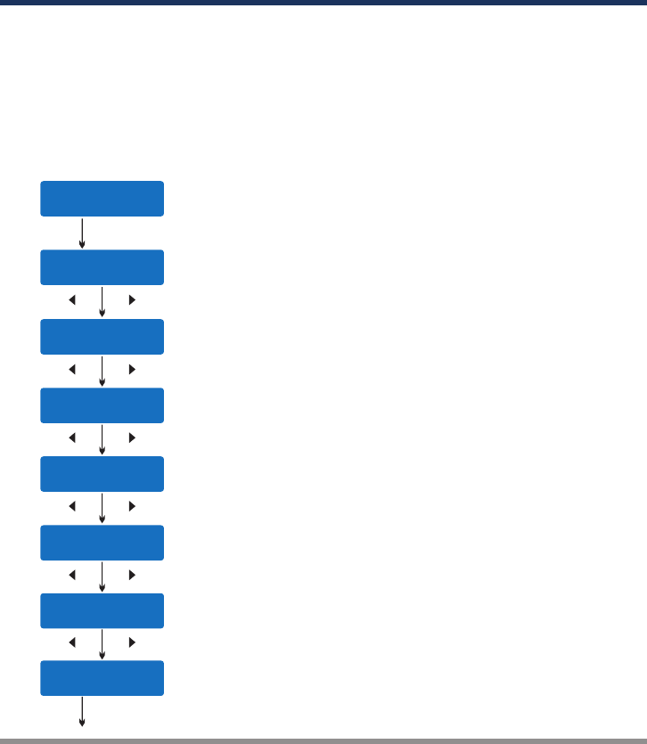
BATTERY MEMORY SET AND CALL OUT
[ BATT MEMORY 1 ]
ENTER SET->
BATT TYPE
LiPo
BATT VOLTS
7.4V ( 2S )
CHARGE CURRENT
4.9A
DSCH CURRENT
2.0A
DSCH VOLTAGE
3.0V/CELL
TVC=YOUR RISK
4.20V
SAVE PROGRAM
ENTER
The charger can store up to 40 different charge/discharge profiles(each channel 10 sets)
for your convenience, and the stored profiles can be recalled quickly without having to go
through the setup process.
When you are willing to alter the parameter value in the program, press START/ENTER to
make it blink then change the value with INC or DEC. The value will be stored by
pressing START/ENTER once.
Note: All following screen are taking 2S(7.4V) LiPo battery for example.
Enter the battery memory program.
(10 different charge/discharge profiles can be stored in each channel).
Set the battery type(LiPo/LiFe/LiIon/LiHV/NiMH/NiCd/Pb).
Set the voltage and number of cells(1S-6S).
Set the charge current(CH A/B 0.1-10.0A / CH C/D 0.1-5.0A).
Set the discharge current (0.1-2.0A).
Set the discharge voltage(3.0-3.3V/Cell).
Set the terminal voltage(4.18-4.25V).
Press ENTER to save program.
1. Battery Memory Set
START/ENTER
DEC INC
DEC INC
DEC INC
DEC INC
DEC INC
DEC INC
START/ENTER
17 ·
Q200
BATTERY MEMORY SET AND CALL OUT
ENTER CHARGER
LOAD……
LiPo BALANCE CHG
4.9A 7.4V(2S)
SAVE PROGRAM
SAVE….
[ BATT MEMORY 1 ]
LiPo 7.4V (2S)
[ BATT MEMORY 1 ]
C:4.9A D:2.2A
Indicate the battery type and battery cell of the saved profile.
Indicate the charge and discharge current of the saved profile.
Press the START/ENTER for 3 seconds to call out the memory.
2. Battery Memory Call Out
Load the memory set
Press START/ENTER for 3 seconds to start the process.
START/ENTER
>3 Seconds
· 18 Q200

SYSTEM SETTING
Safety Timer
ON 120Min
Rest Time
CHG>DCHG 10Min
Capacity Cut-Off
ON 5000mAH
Temperature Unit
Celsius
Temp Cut-Off
ON 50°C 122°F
This program sets the maximum charge
capacity that will be supplied to the battery
during charge. If the delta peak voltage is
not detected nor the safety timer expired by
any reason, this feature will automatically
stop the process at the selected capacity
value.
When you start a charge process, the
integral safety timer automatically starts
running at the same time. This is
programmed to prevent overcharge the
battery if it proves to be faulty, or if the
termination circuit cannot detect the battery
full. The value for the safety timer should be
generous enough to allow a full charge of
the battery.
The battery's internal chemical reaction will
cause the temperature of the battery to
rise. If the temperature limit is reached, the
process will be terminated.
OFF/
ON
(100-50000 mAh)
It will be operated with the default value of the essential user settings when it is powered
on for the first time.The screen displays the following information in sequence and the
user can change the value of parameter on each screen.
When you are willing to alter the parameter value in the program, press START/ENTER to
make it blink then change the value with INC or DEC. The value will be stored by
pressing START/ENTER once.
ITEM SELECTION DESCRIPTION
OFF/
ON
(1-720 Min)
OFF/
ON
(20 C/68 F -
80 C/176 F)
Celsius
Fahrenheit
1-60Min A rest time allowing the battery to cool
down between charging/discharging cycle.
You can choose the temperature displayed
by Celsius or Fahrenheit as you like.
19 ·
Q200
ITEM SELECTION DESCRIPTION
SYSTEM SETTING
NiMHSensitivity
D.Peak Default
NiCdSensitivity
D.Peak Default
Default: 4mV/Cell
5-15mV/Cell
Key Beep ON
Buzzer ON OFF/ON
The beep sounds at every time touching
the buttons to confirm your action. The
beep or melody sounded at various times
during operation to alert different mode
changes.
Input. Power Low
Cut-Off 11.0V 10.0-11.0V
This program monitors the voltage of input
battery. If the voltage drops below the value
you set the operation forcibly terminated to
protect the input battery.
This program is for NiMH/NiCd battery only.
When the charger detects the delta peak
value reaches the value you set, the
charger will say the battery is fully charged.
Load Factory Set
Enter
Version
HW:1.00 FW: 1.10
Press ENTER to load factory default setting.
It indicates the hardware and firmware
version.
AC Max Power Set
100W 0-100W
It is to set the max AC power of the present
channel. Once you set it, the another
channel will take the rest.
Max Charge Power for CH A/CH B 100W
Max Charge Power for CH C/CH D 50W
BAL.Connection
ON
The default setting for charging Lithium
battery is using balance adaptor to connect
battery and charger in Charge, Fast
Charge, Balance Charge and Storage
modes. This function could be disabled
here.
OFF/ON
· 20 Q200

BATTERY METER
The user can check battery's total voltage, the highest voltage, the lowest voltage and
each cell's voltage.
Please connect the battery to the charger main battery lead to battery socket and balance
wires to balance socket.
BATT/PROGRAM
BATT METER
4.20 4.19 4.19 V
4.18 4.18 4.19 V
MAIN 25.13V
H4.200V L4.182V
Press the START/ENTER to enter the Lithium
Battery Meter program.
The screen indicate each cell's voltage.
The screen indicate the total voltage, the highest
voltage and the lowest voltage.
START
ENTER
DEC
This diagram shows the correct way to connect your battery
to check the voltage.
INC
Battery
Pack
Battery
Pack
Battery
Pack
Battery
Pack
21 ·
Q200
A
B
C
D
4.19 4.15 4.18V
4.15 4.19 4.18V
4.19 4.15 4.18V
4.15 4.19 4.18V
4.19 4.15 4.18V
4.15 4.19 4.18V
4.19 4.15 4.18V
4.15 4.19 4.18V
BATTERY RESISTANCE METER
The user can check battery's total resistance, the highest resistance, the lowest
resistance and each cell's resistance.
Please connect the battery to the charger main battery lead to battery socket and balance
wires to balance socket.
Press the START/ENTER to enter the Lithium
Battery Resistance program.
The screen indicate each cell's resistance.
The screen indicate the total resistance, the highest
resistance and the lowest resistance.
Start
Enter
BATT/PROGRAM
BATT RESISTANCE
012 005 005 mΩ
006 mΩ
TATAL:28mΩ
H:12mΩ L:5mΩ
DEC
This diagram shows the correct way to connect your battery to
check the resistance.
INC
Battery
Pack
Battery
Pack
Battery
Pack
Battery
Pack
A
B
C
D
005 003 003 mΩ
005 003 003 mΩ
005 003 003 mΩ
005 003 003 mΩ
005 003 003 mΩ
005 003 003 mΩ
005 003 003 mΩ
005 003 003 mΩ
· 22 Q200

WARNING AND ERROR MESSAGE
In case of an error the screen will display the cause of error and emit an audible sound.
Incorrect polarity connected.
The battery is interrupted.
CONNECT ERROR
CHECK MAIN PORT Thebattery connection is wrong.
The cell number is wrong.
CELL NUMBER
INCORRECT
Voltage of one cell in the battery pack is too high.
CELL ERROR
HIGH VOLTAGE
Voltage of one cell in the battery pack is too low.
CELL ERROR
LOW VOLTAGE
The internal temperature of the unit goes too high.
INT.TEMP.TOO HI
DC IN TOO LOW Input voltage less than 11V.
Input voltage higher than 18V.
DC IN TOO HIGH
BATTERY WAS FULL The battery voltage is higher than the maximum voltage
which the user sets when charging in balance mode.
CELL ERROR
VOLTAGE-INVALID Voltage of one cell in the battery pack is invalid.
The external temperature of the battery goes too high.
EXT.TEMP.TOO HI
OVER CHARGE
CAPACITY LIMIT
The battery capacity is more than the maximum capacity
which the user sets.
OVER TIME LIMIT The charging time is longer than the maximum charging
time which the user sets.
BALANCE CONNECT
ERROR Thebalanceconnectiswrong.
CONNECTION BREAK
REVERSE POLARITY
23 ·
Q200
The free “Charge Master” software gives you unparalleled ability to operate the charger
through the computer. You can monitor pack voltage, cell voltage and other data during
the charging, view charge date in real-time graphs. And you can initiate, control charging
and update firmware from “Charge Master”.
In order to connect the charger to the computer and use the “Charge Master”, you are
required to use a USB cable which is not included in this package. The cable must be
terminated on one end with “A” plug and the opposite end is terminated with “micro-B”
plug which can connect to charger directly.
You can control, monitor, operate and upgrade two channels with one computer.
The “Charge Master” can be download from www.skyrc.com.
USING THE CHARGE CONTROL SOFTWARE
“CHARGE MASTER”
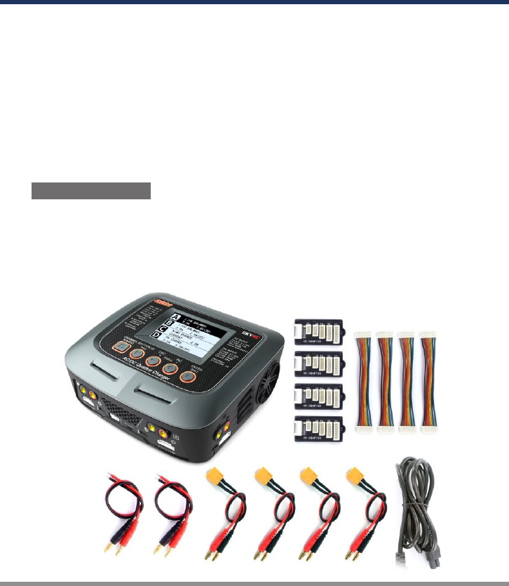
THESETCONTAINS
1
2
1. SKYRC Q200 Charger
2. XH Adaptor X 4
3. Charging Cable X 2
4. Banana Connectors with XT60 Connector Charging Cable X 4
5. Power Cord
· 24 Q200
3 4 5

SPECIFICATION
DC Input Voltage : 11-18V AC Input Voltage: 100-240V
Display Type: Colorful 480x320 LCD Display Backlight: Cool White
Case Material: Plastic Controls: Five Buttons
Case Size: 197x182x71mm Weight: 1325g
PC Communications: USB Port for PC Control & Firmware Upgrade
External Port: 2-6S Balance Socket-XH, Temperature Probe Socket,
Battery Socket, DC Input, Micro USB Port for PC, 5V/2.1A USB Port.
Delta Peak Detection for NiMH/NiCd: 3-15mV/cell / Default: 4mV/cell
Charge Cutoff Temperature: 20ºC/68ºF-80ºC/176ºF(adjustable)
Charge Voltage: NiMH/NiCd: Delta peak detection
LiPo: 4.18-4.25V/cell LiIon: 4.08-4.2V/cell
LiFe: 3.58-3.7V/cell LiHV: 4.25-4.35V/cell
Balance Current: 200mA/cell
Reading Voltage Range: 0.1-26.1V/cell
Battery Types/Cells: LiPo/LiIon/LiFe/LiHV: 1-6cells
NiMH/NiCd: 1-15cells
Pb: 2-20V
Battery Capacity Range: NiMH/NiCd: 100-50000mAh
LiPo/LiIon/LiFe/LiHV: 100-50000mAh
Pb: 100-50000mAh
Charge Current: Channel A/B: 0.1-10A; Channel C/D: 0.1-5A
Safety Timer: 1-720minutes off
Charge Wattage: AC CHA+CHC=100W CHB+CHD=100W
(CHA/CHB: 50-100W CHC/CHD: 0-50W)
DC CHA/CHB: 100W CHC/CHD: 50W
Discharge Current: (0.1A-2.0A) x4
Discharge Cut-off Voltage: NiMH/NiCd: 0.1-1.1V/cell
LiPo: 3.0-3.3V/cell LiIon: 2.9—3.2V/cell
LiFe: 2.6-2.9V/cell LiHV: 3.1-3.4V/cell
Pb: 1.8V
Discharge Wattage: 10Wx4
Balance Cells: 2-6 cells
Memory: 10x4 Different Charge/Discharge Profiles
Charge Method: CC/CV for Lithium Types and Lead (Pb) Batteries
Delta-peak Sensitivity for NiMH/NiCd.
25 ·
Q200
CONFORMITY DECLARATION
· 26 Q200
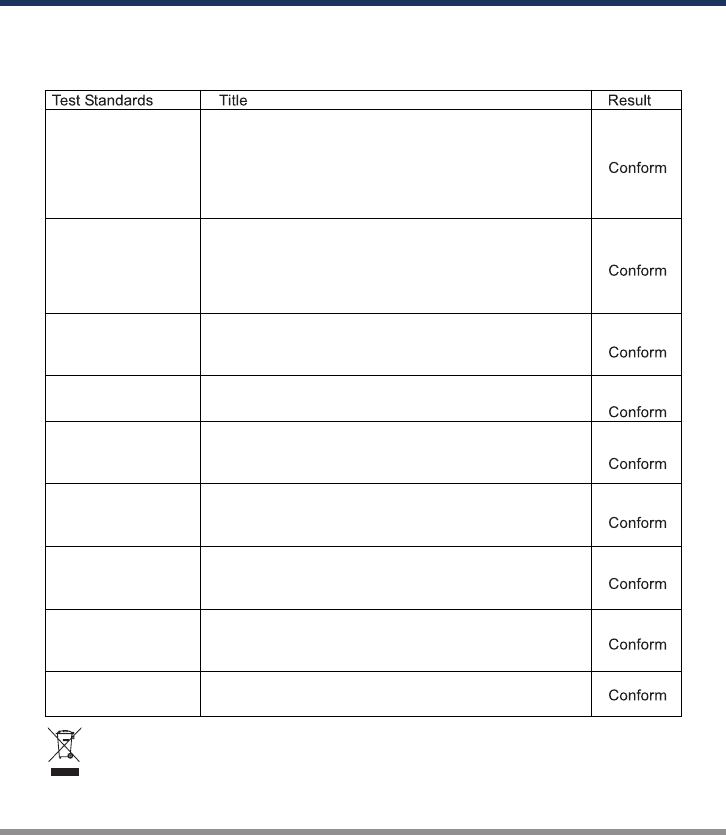
This symbol means that you must dispose of electrical from the General household waste when
it reaches the end of its useful life. Take your charger to your local waste collection point or
recycling centre. This applies to all countries of the European Union, and to other European
countries with a separate waste collection system.
D200 satisfy all relevant and mandatory CE directives and FCC Part 15 Subpart B: 2014.
For EC directives:
The product has been tested to meet the following technical standards:
EN 300328
EN 301489-1
EN 301489-17
EN 62479
EN 60950-1
Electromagnetic compatibility and Radio spectrum
Matters (ERM); Wideband transmission systems; Data
transmission equipment operating in the 2.4 GHz ISM
band and using wide band modulation techniques;
Harmonized EN covering essential requirements under
article 3.2 of the R&TTE Directive.
Electromagnetic compatibility and Radio spectrum
Matters (ERM); ElectroMagnetic Compatibility (EMC)
standard for radio equipment and services; Part 1:
Common technical requirements. Part 17: Specific
conditions for Broadband Data Transmission Systems.
Assessment of electronic and electrical equipment related
to human exposure restrictions for electromagnetic fields
(0 Hz - 300 Ghz).
Information Technology Equipment-Safety- Part 1: General
Requirements
EN 55014-2
EN 61000-3-2
Electromagnetic Compatibility (EMC) Part 3-2: Limits for
harmonic current emissions (Equipment input current up
to and including 16A per phase).
EN 55014-1
Electromagnetic Compatibility - Requirements for
household appliances, electric tools and similar apparatus
- Part 1: Emission.
Electromagnetic Compatibility - Requirements For
Household Appliances, Electric Tools And Similar
Apparatus - Part 2: Immunity Product Family Standard.
EN 61000-3-3
Electromagnetic Compatibility (EMC) Part 3-3: Limitation
of voltage supply systems for equipment with rated
current ≤ 16A
Part 15 Section
15.247
Operation within the bands 902 - 928 MHZ, 2400 -
2483.5 MHz, and 5725 - 5850 MHz.

Commonly used terms
Final charge voltage: the voltage at which the battery's charge limit (capacity limit) is
reached. The charge process switches from a high current to a low maintenance rate
(trickle charge) at this point. From this point on further high current charging would cause
overheating and eventual terminal damage to the pack.
Final discharge voltage: the voltage at which the battery's discharge limit is reached. The
chemical composition of the batteries determines the level of this voltage. Below this
voltage the battery enters the deep discharge zone. Individual cells within the pack may
become reverse polarized in this condition, and this can cause permanent damage.
A, mA: unit of measurement relating to charge or discharge current.1000 mA = 1 A
(A=Ampere,mA=Milliampere)
Ah, mAh: unit of measurement for the capacity of a battery (Amperes x time unit; h = hour).
If a pack is charged for one hour at a current of 2 A, it has been fed 2 Ah of energy. It
receives the same quantity of charge (2 Ah) if it is charged for 4 hours at 0.5 A, or 15
minutes (=1/4 h) at 8 A.
'C'-rating: Capacity is also referred to as the 'C' rating. Some battery suppliers recommend
charge and discharge currents based on the battery 'C' rating. A battery's '1C' current is the
same number as the battery's rated capacity number, but noted in mA or amps. A 600mAh
battery has a 1C current value of 600mA, and a 3C current value of (3 x 600mA) 1800mA or
1.8A. The 1C current value for a 3200mAh battery would be 3200mA (3.2A).
Nominal voltage(V): The nominal voltage of the battery pack can be determined as follows;
-.NiCd or NiMH: multiply the total number of cells in the pack by 1.2. A 8-cell pack will have a
nominal voltage of 9.6 volts (8x1.2).
-.LiPo: multiply the total number of cells in the pack by 3.7. A 3-cell LiPo wired in series will
have a nominal voltage of 11.1 volts (3x3.7).
-.LiIo: multiply the total number of cells in the pack by 3.6. A 2-cell LiIo wired in series will have
a nominal voltage of 7.2 volts (2x3.6).
-.LiFe: multiply the total number of cells in the pack by 3.3. A 4-cell LiIo wired in series will have
a nominal voltage of 13.2 volts (4x3.3).
-.LiHV: multiply the total number of cells in the pack by 3.7V. A 4-cell LiHV wired in series will
have a nominal voltage of 14.8 volts (4x3.7).
If the nominal voltage of the battery is not printed on the battery's label, consult your battery
manufacturer or supplier. Do not guess the rated voltage of battery.
COMMONLY USED TERMS
27 ·
Q200

WARRANTY AND SERVICE
This charger is designed and approved exclusively for use with the types of battery stated
in this Instruction Manual. SkyRC accepts no liability of any kind if the charger is used for
any purpose other than that stated.
We are unable to ensure that you follow the instructions supplied with the charger, and
we have no control over the methods you employ for using, operating and maintaining the
device. For this reason we are obliged to deny all liability for loss, damage or costs which
are incurred due to the incompetent or incorrect use and operation of our products, or
which are connected with such operation in any way.Unless otherwise prescribed by law,
our obligation to pay compensation, regardless of the legal argument employed, is limited
to the invoice value of those SkyRC products which were immediately and directly
involved in the event in which the damage occurred.
Liability exclusion
Warranty and service
We guarantee this product to be free of manufacturing and assembly defects for a period of
one year from the time of purchase. The warranty only applies to material or operational
defects, which are present at the time of purchase. During that period, we will repair or
replace free of service charge for products deemed defective due to those causes.
This warranty is not valid for any damage or subsequent damage arising as a result of misuse,
modification or as a result of failure to observe the procedures outlined in this manual.
The warranty service is valid in China only.
If you need warranty service overseas, please contact your dealer in the first
instance, who is responsible for processing guarantee claims overseas. Due
to high shipping cost, complicated custom clearance procedures to send
back to China. Please understand SkyRC can't provide warranty service to
overseas end user directly.
If you have any questions which are not mentioned in the manual, please
feel free to send email to info@skyrc.cn
Note:
1.
2.
3.
· 28 Q200

Printed in China 2016.02
All specifications and figures are subject to change without notice.
Manufactured by
SKYRC TECHNOLOGY CO., LTD.
www.skyrc.com
7504-0601-01
FCC ID:REY-Q200