SMC Networks D3GN4 Wireless Gateway User Manual
SMC Networks Inc Wireless Gateway
UserManual.wiki
>
SMC Networks
>
D3GN4 User Manual
User Manual
Navigation menu
Upload a User Manual
Namespaces
Wiki Guide
HTML
PDF
Info
Views
User Manual
Discussion / Help
Navigation
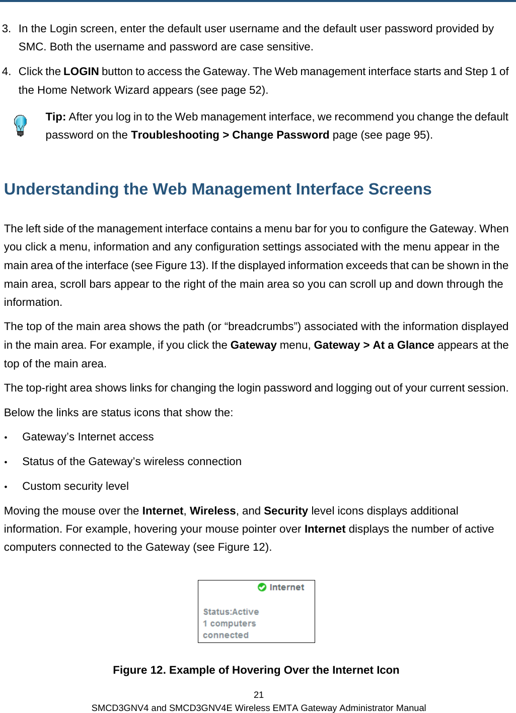
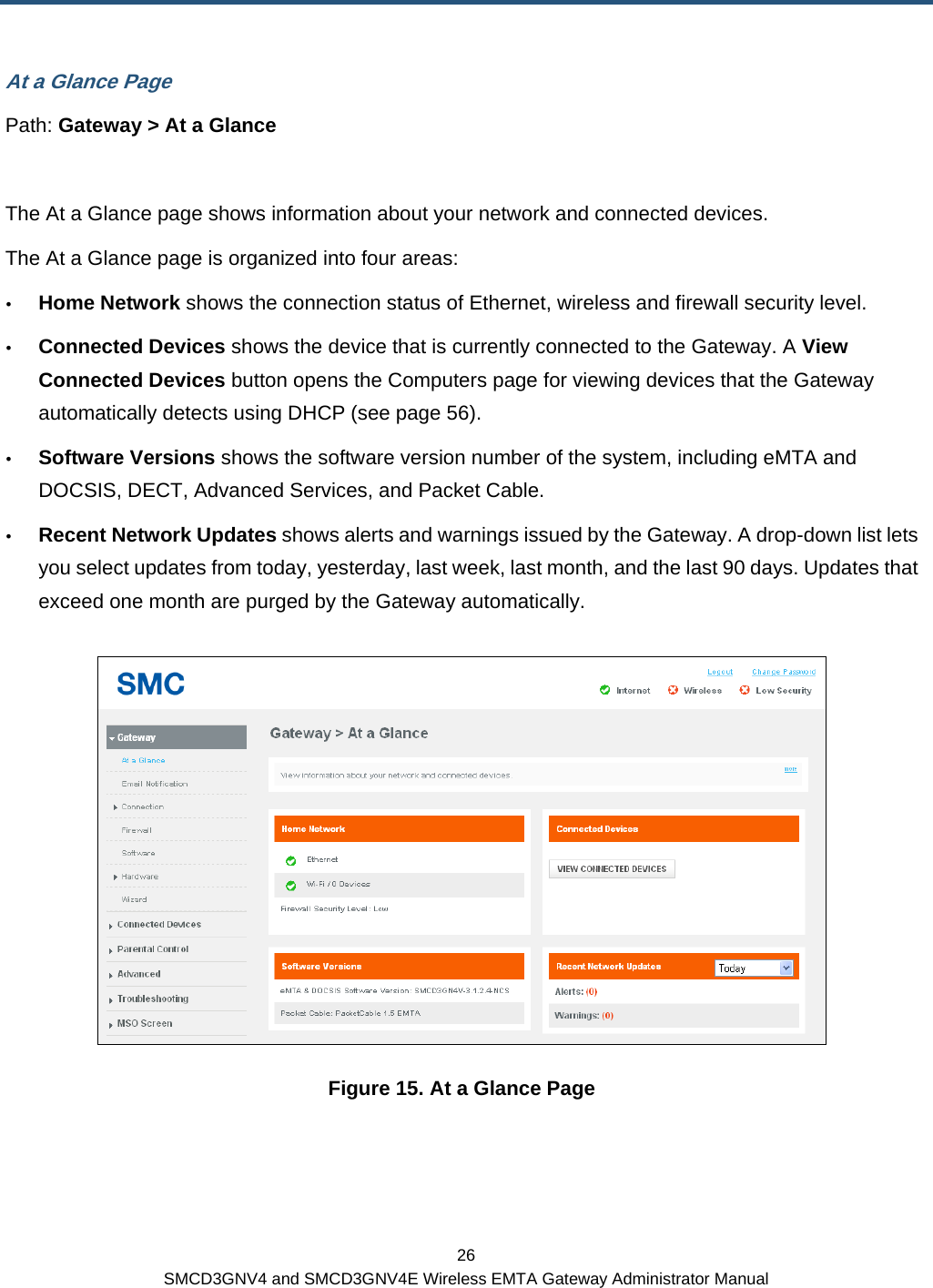
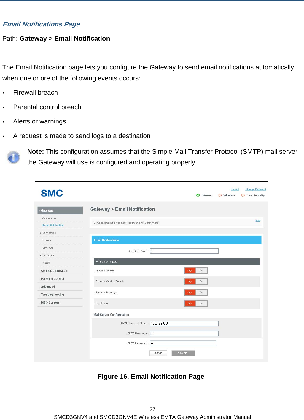
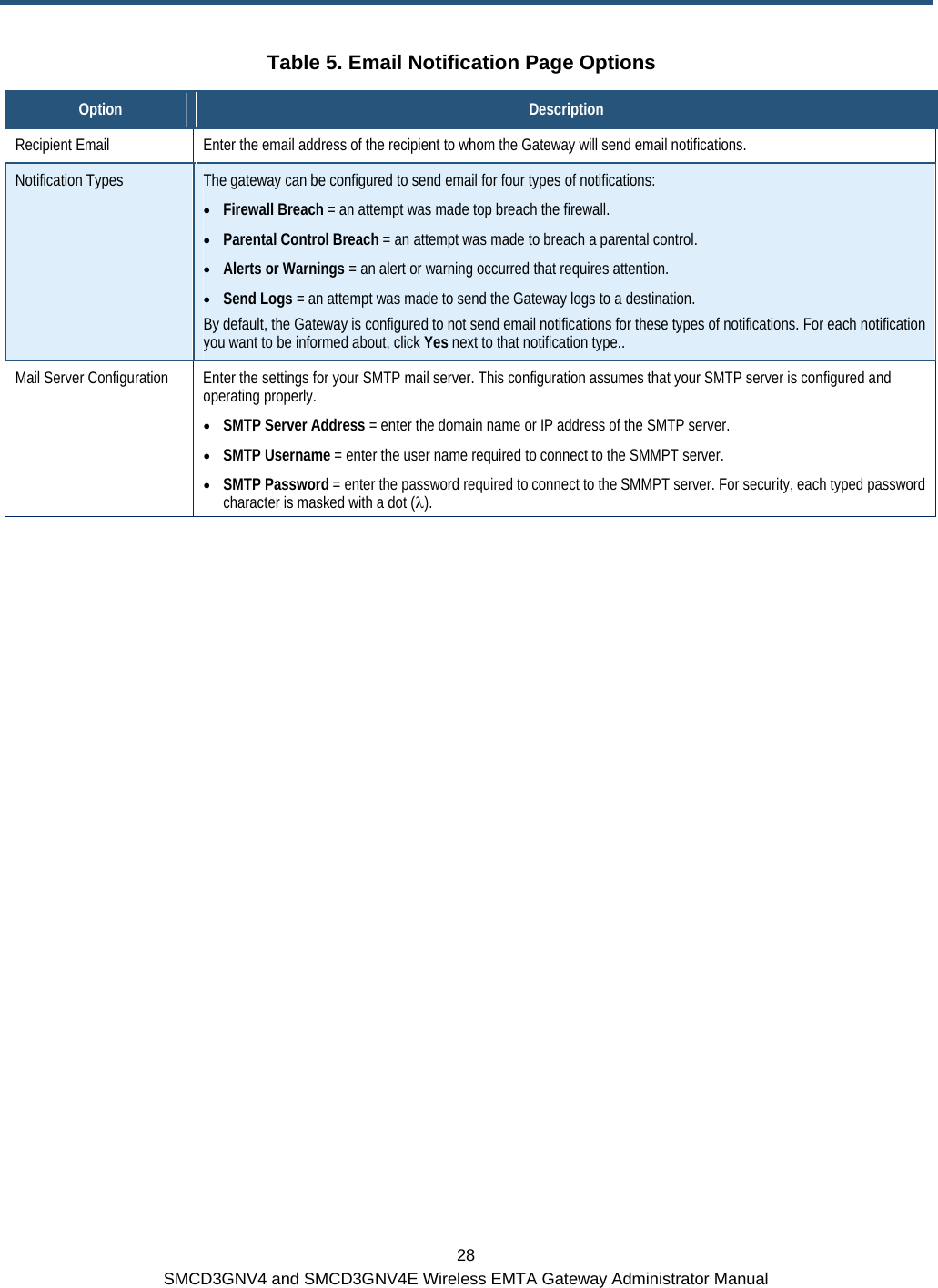
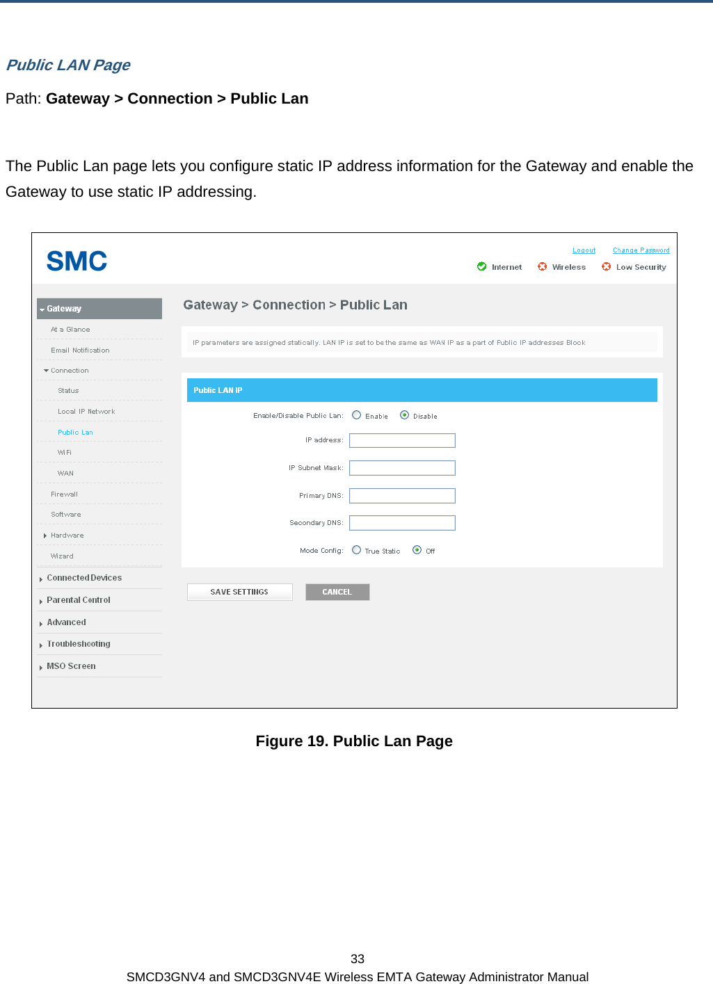
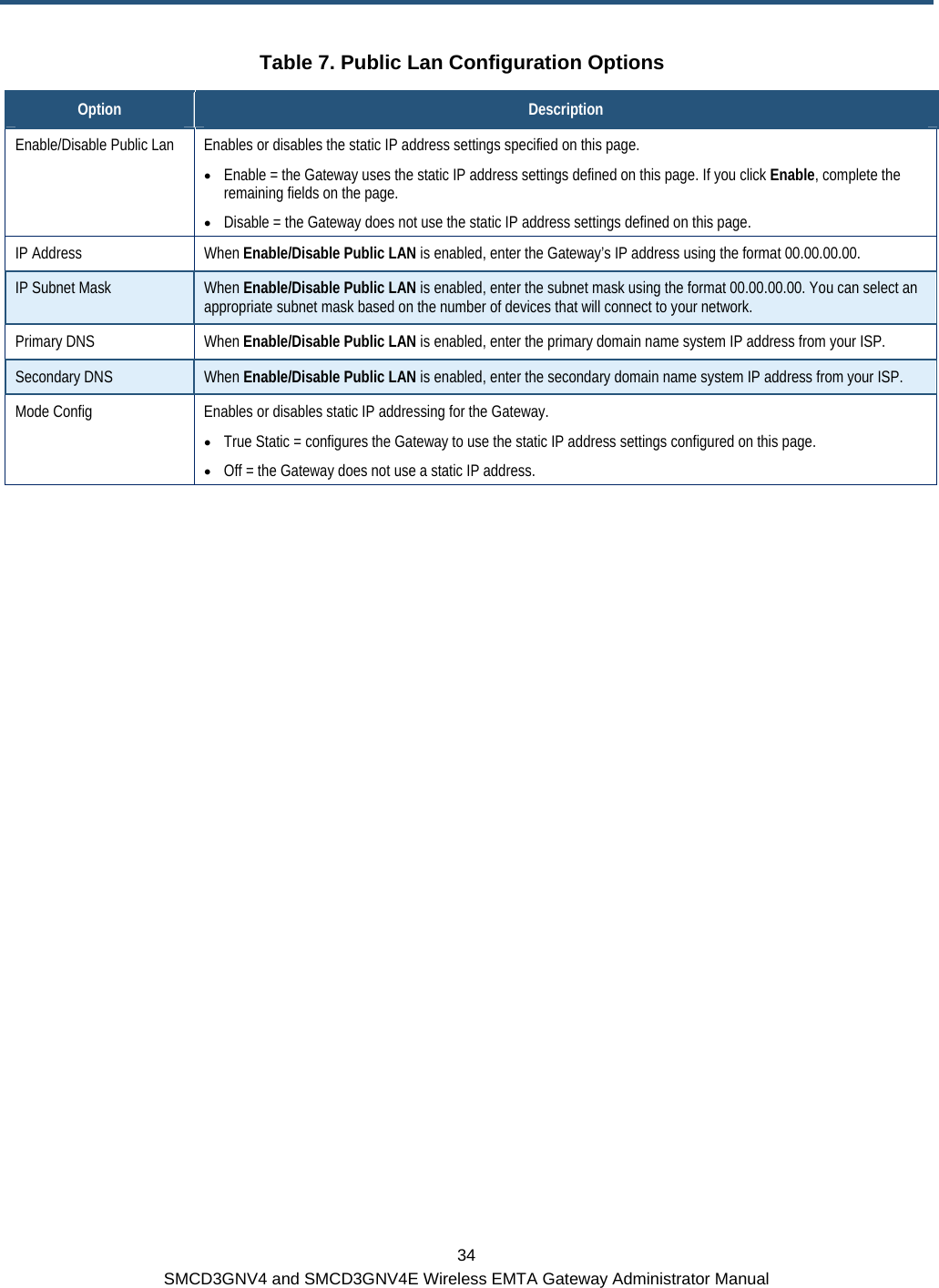
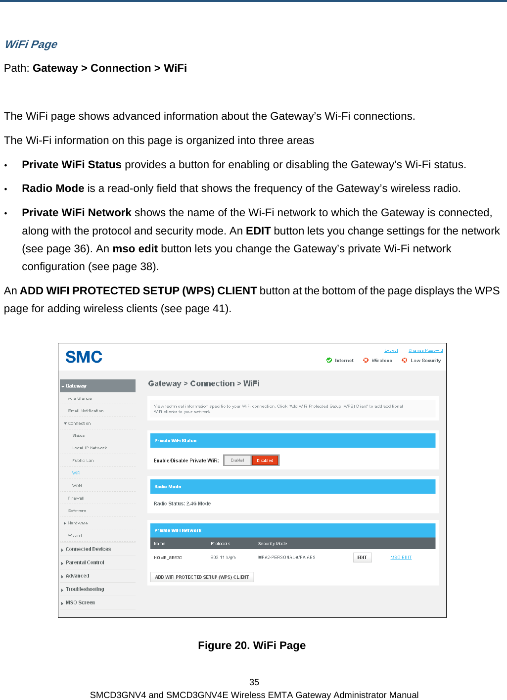
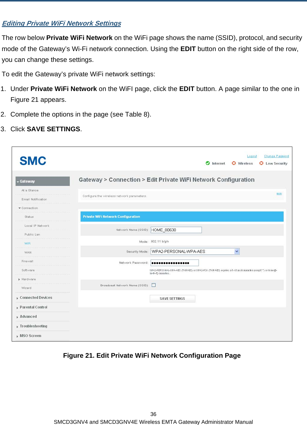
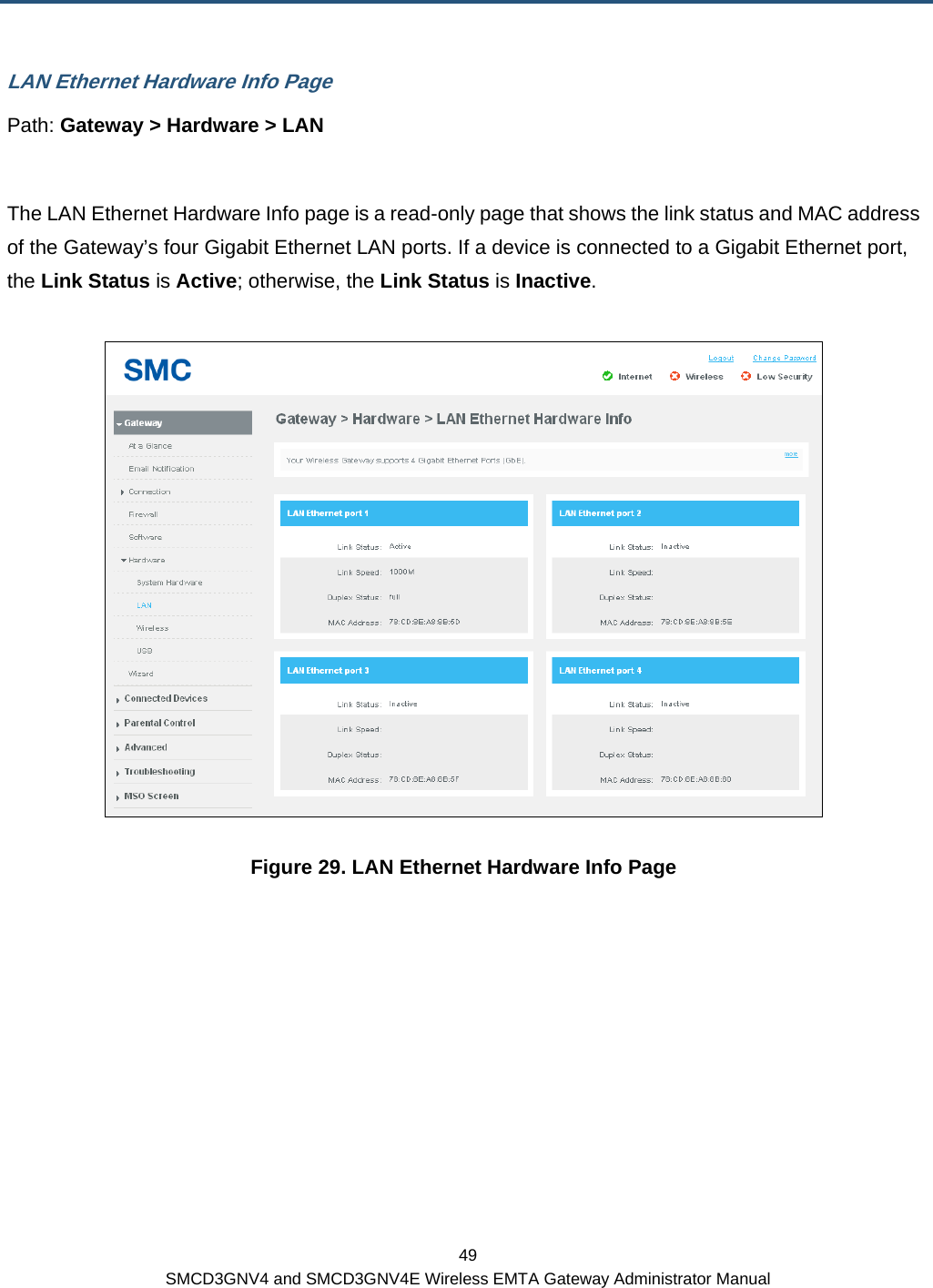
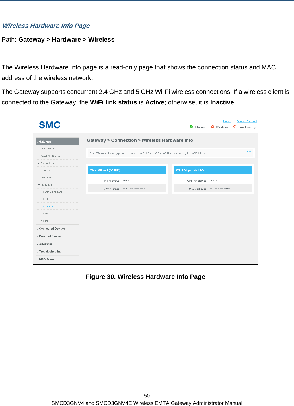
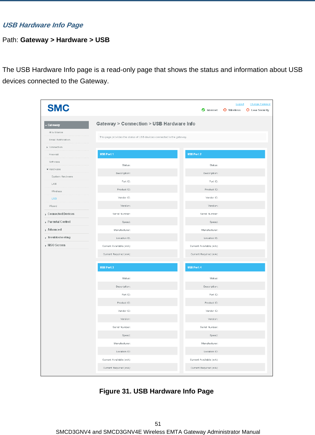
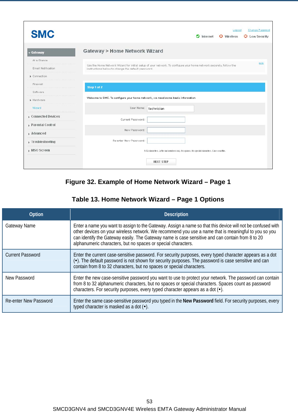
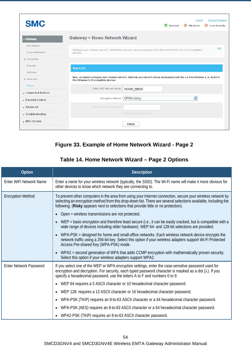
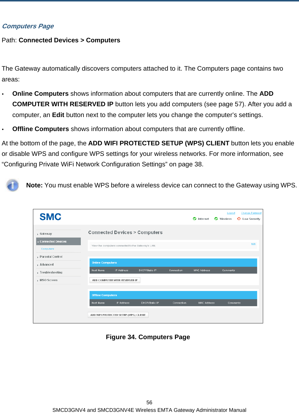
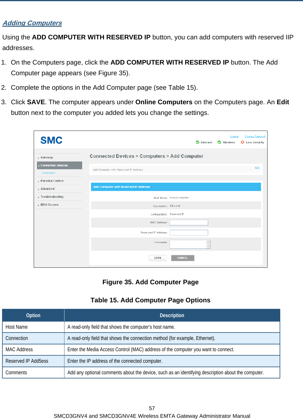

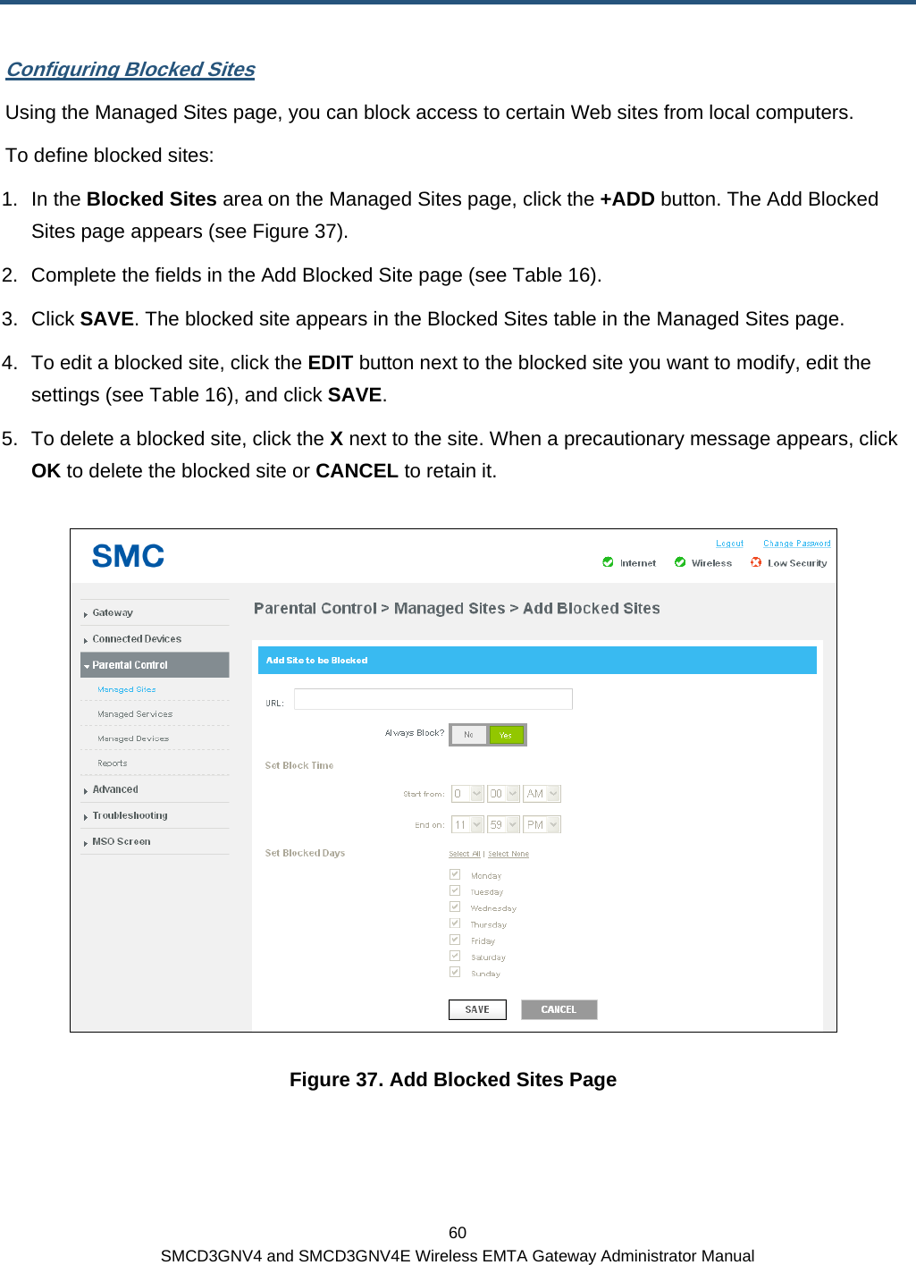
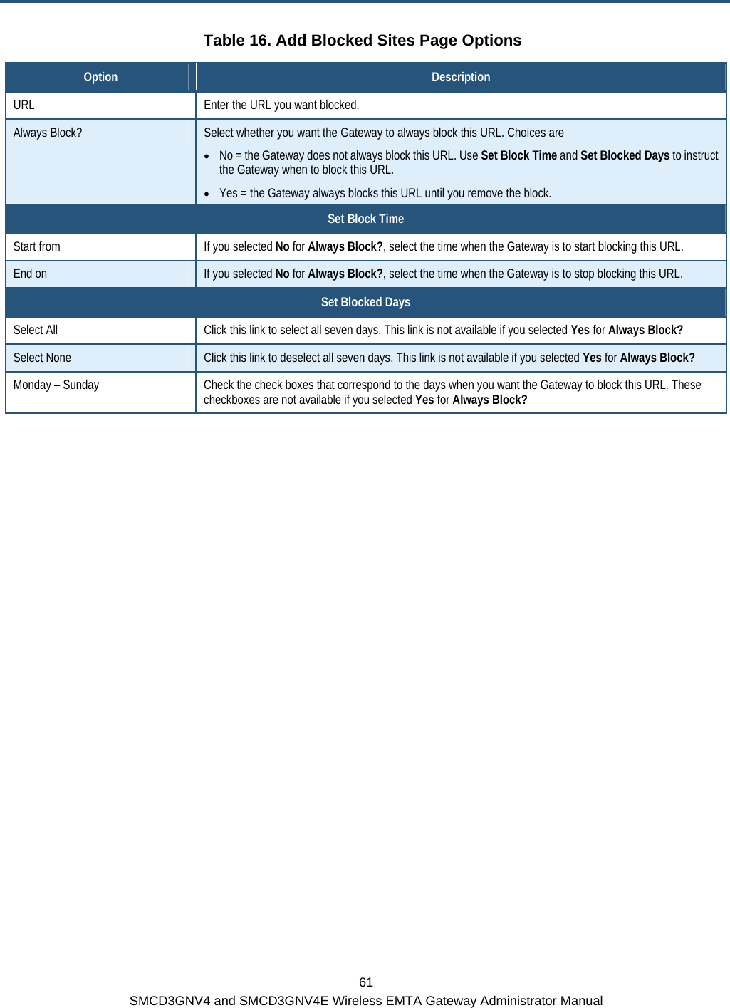
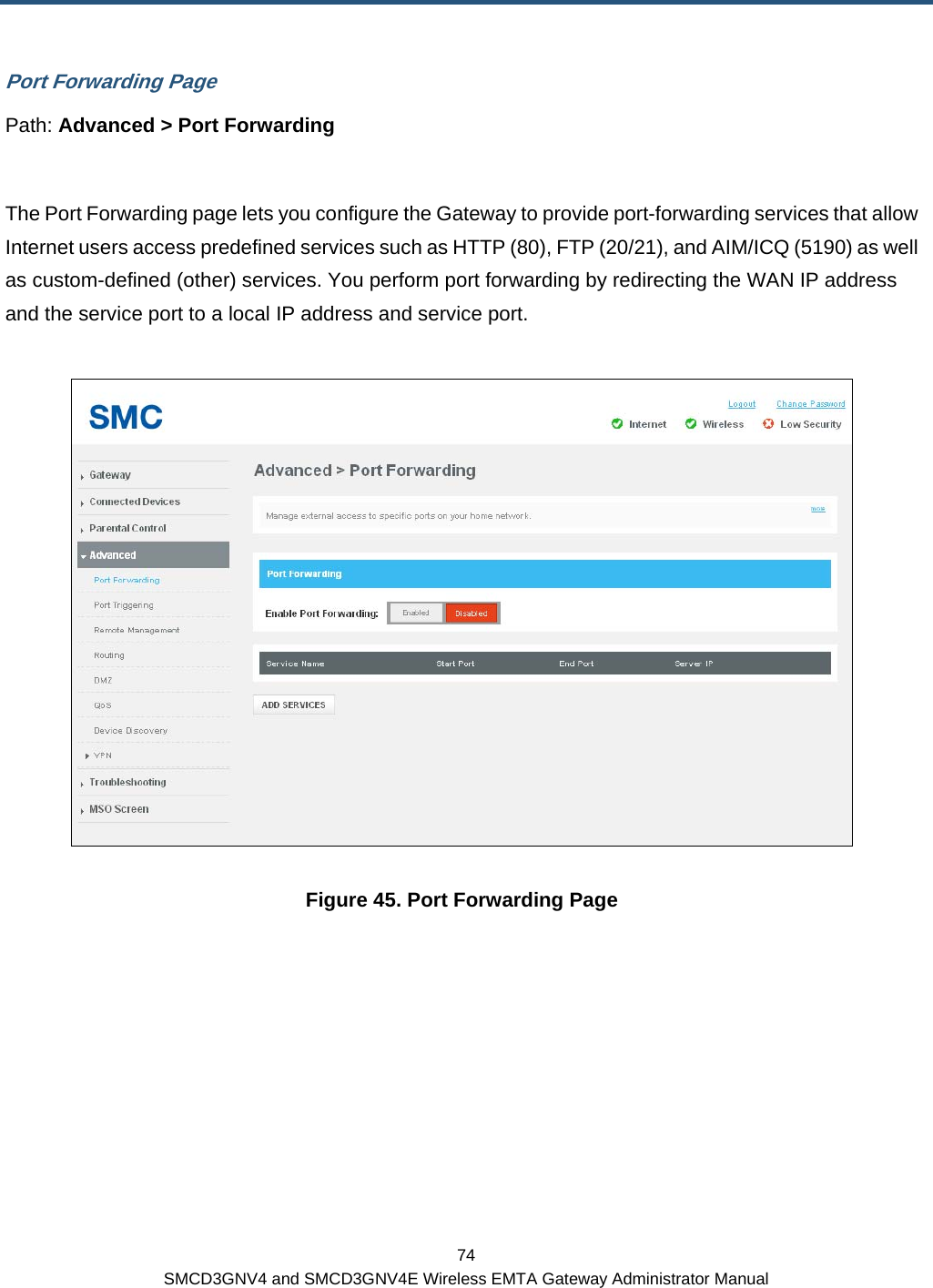
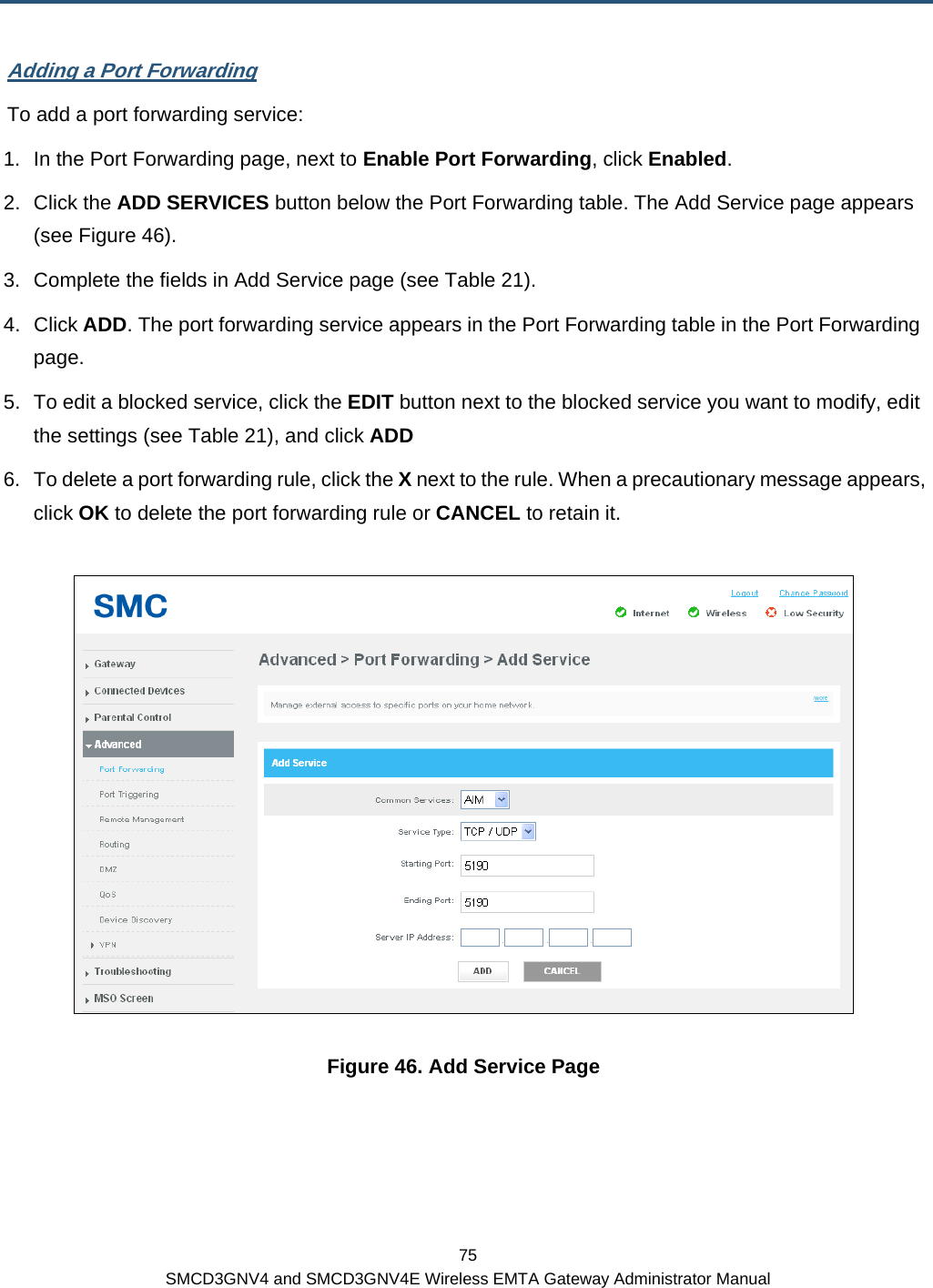
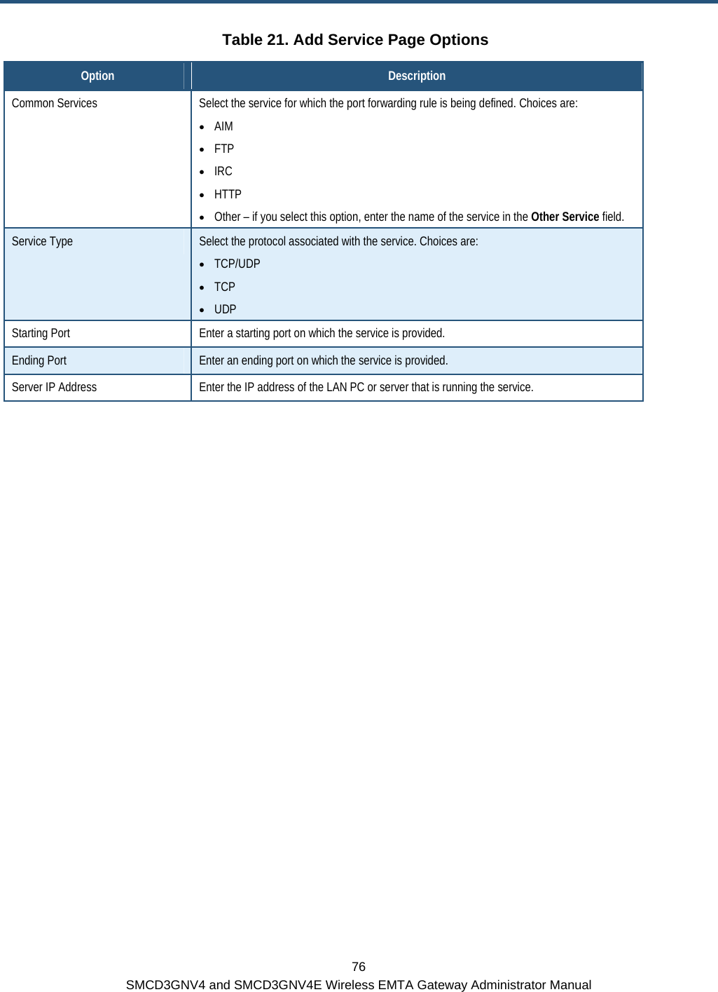
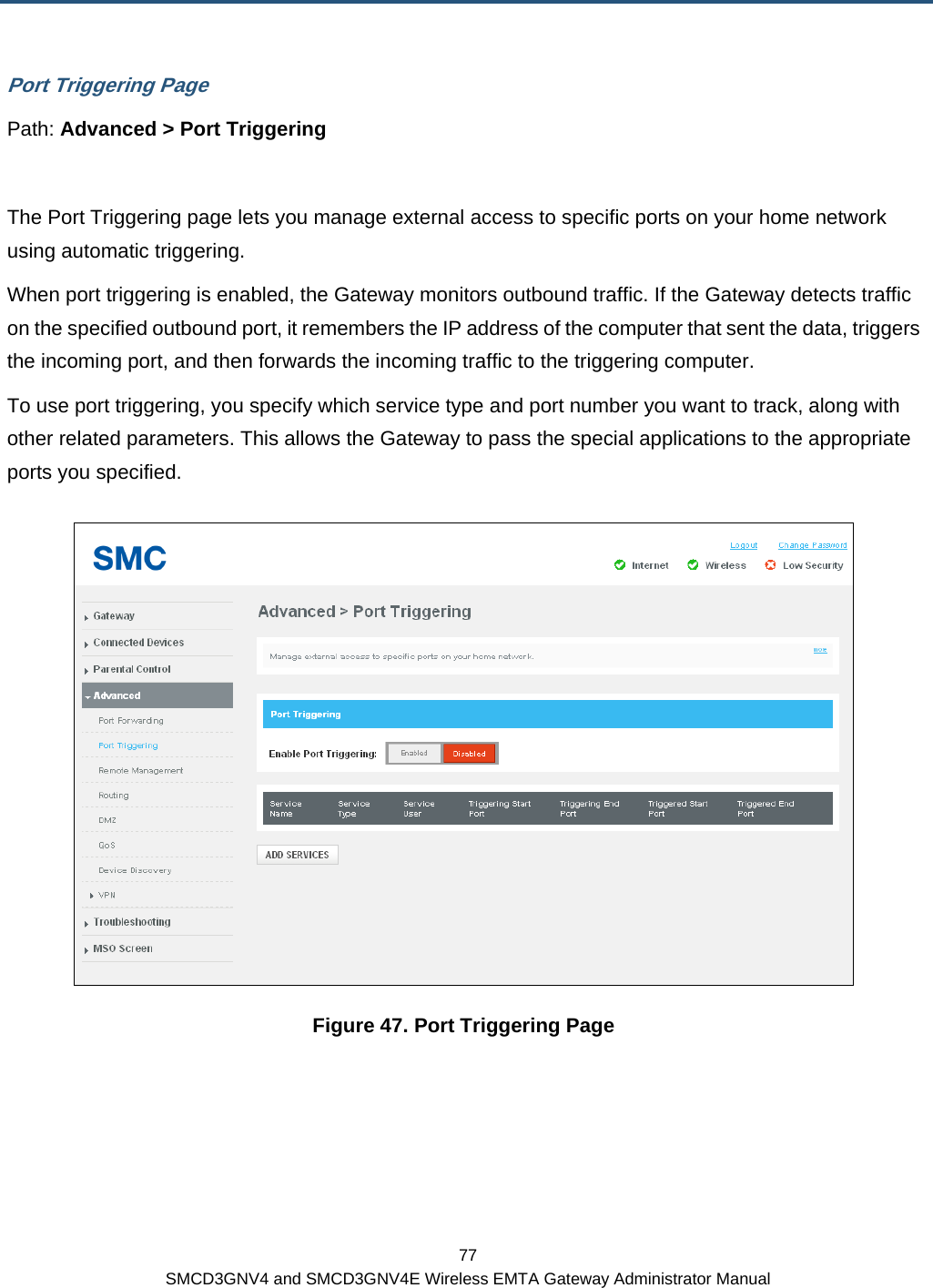
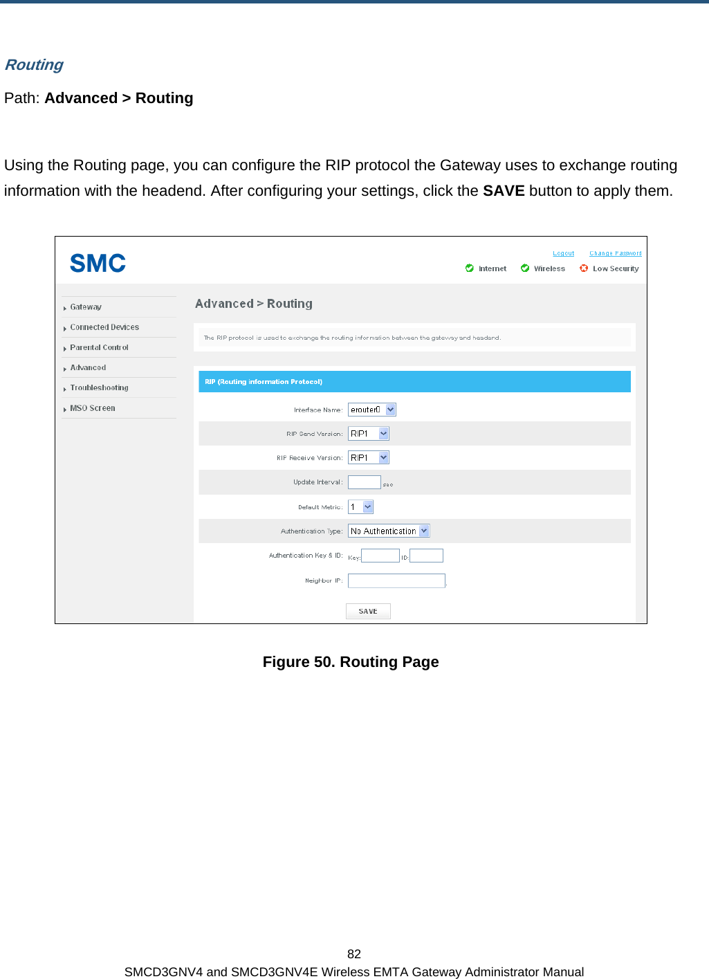
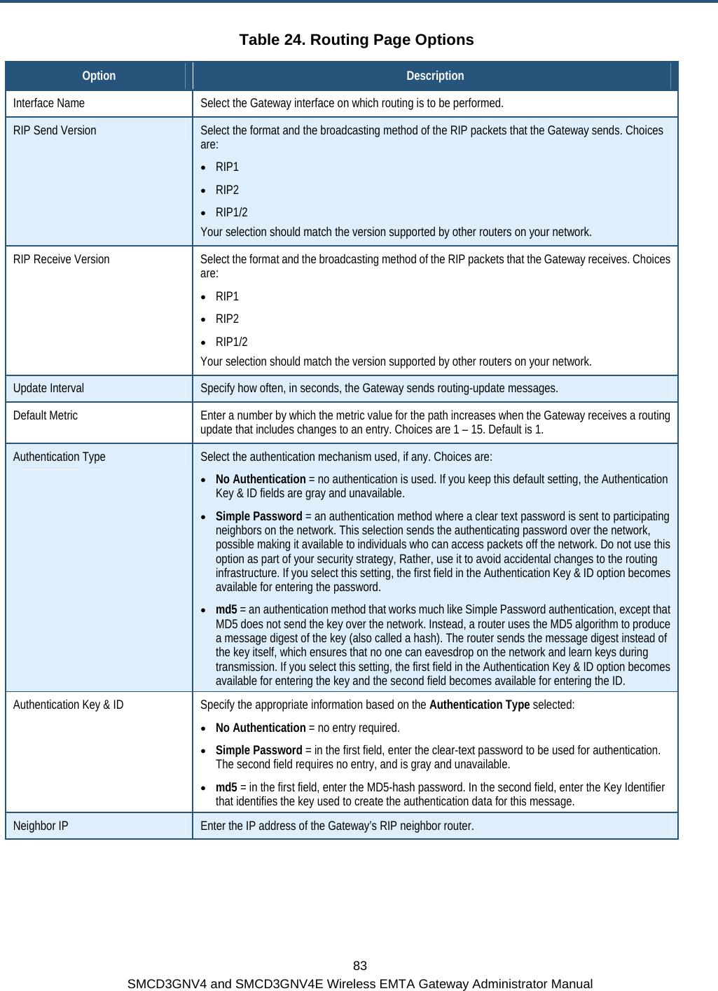
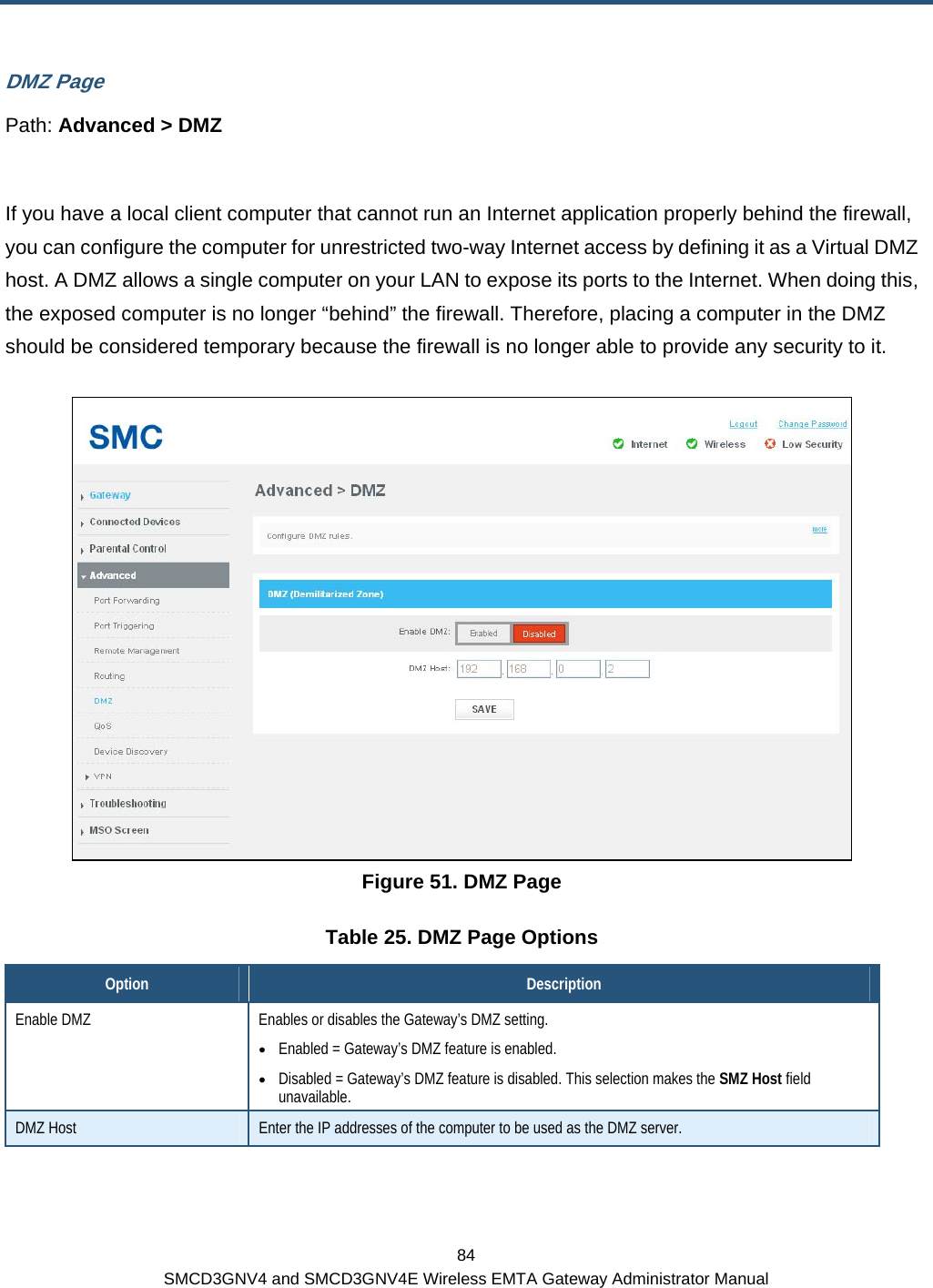
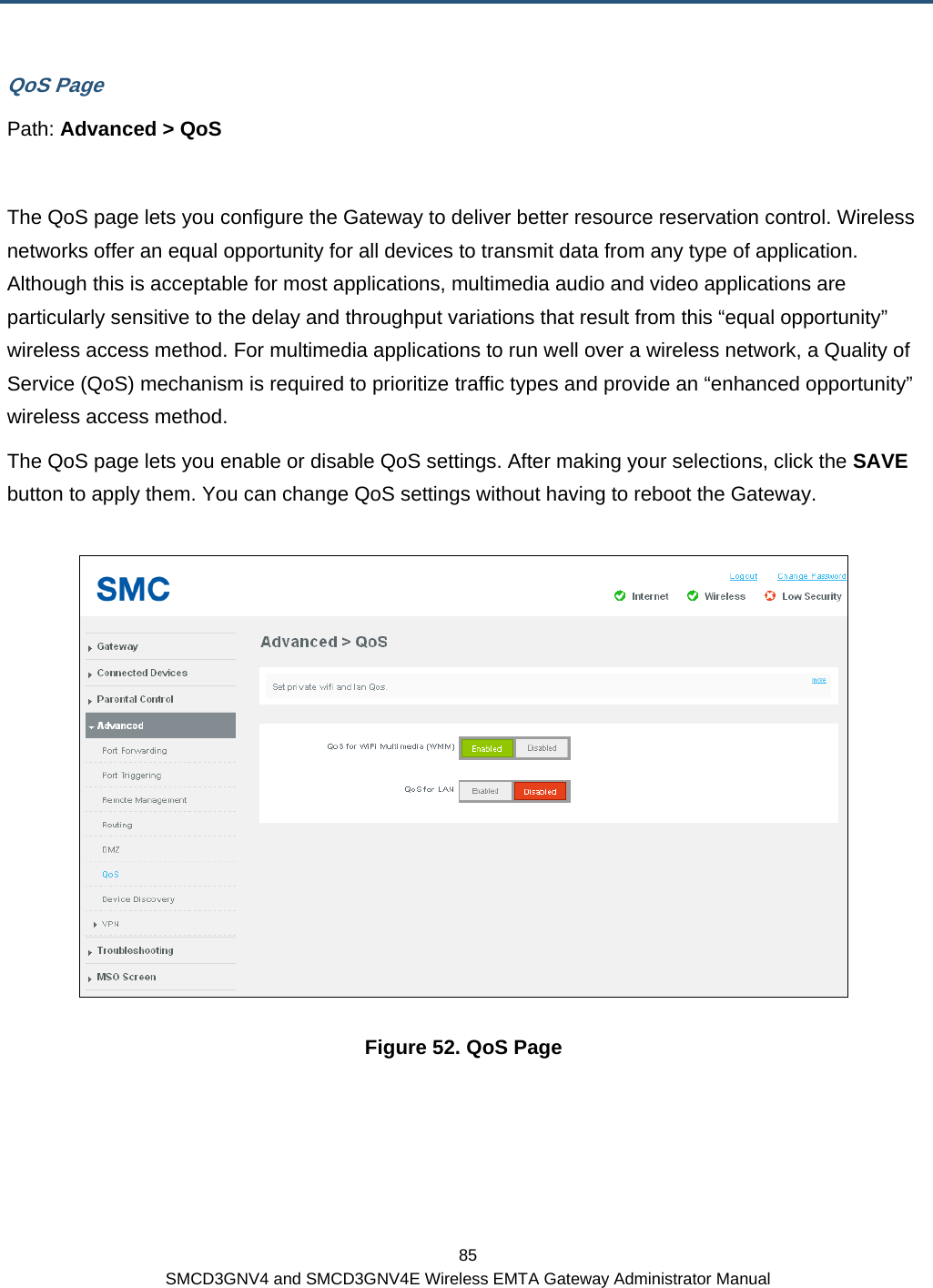
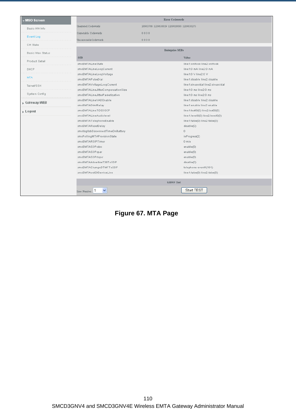
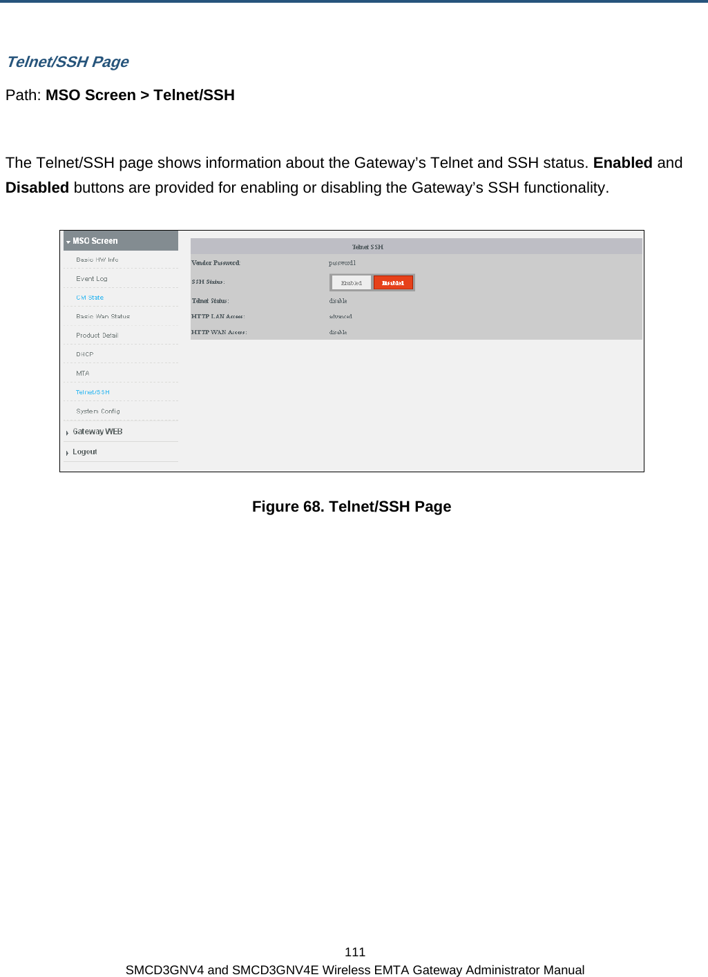
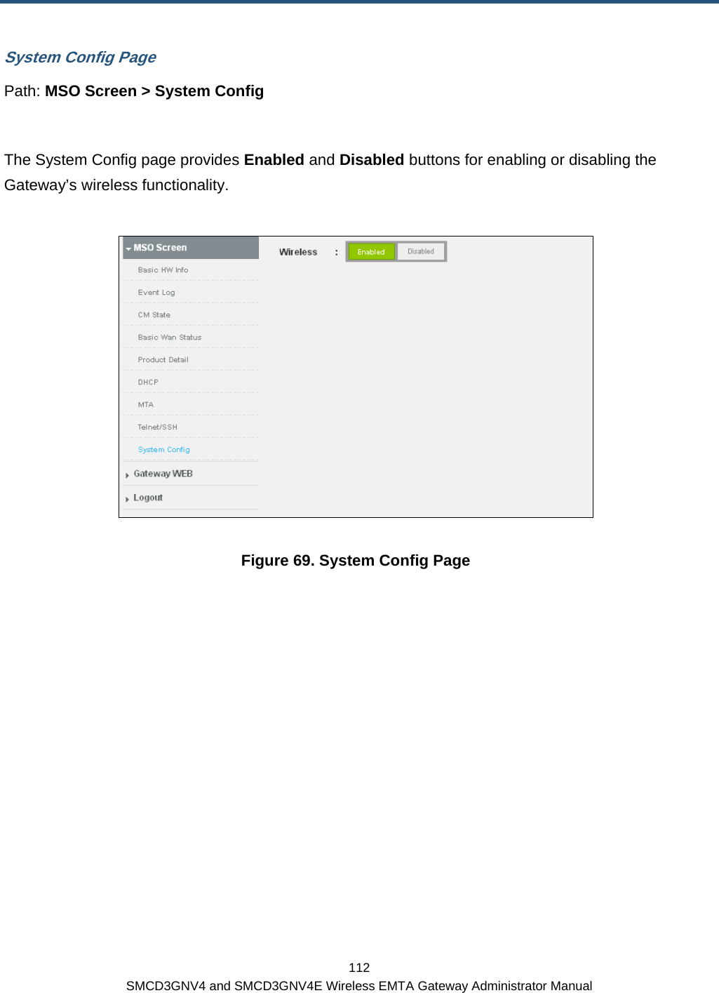
![113 SMCD3GNV4 and SMCD3GNV4E Wireless EMTA Gateway Administrator Manual Appendix A - Wall-Mounting the Gateway The Gateway can be mounted on a wall. Wall mounting requires hanging the Gateway along its width or length using the three slots on the bottom of the unit and the Gateway mounting template (on the next page) for the screws. WARNING: The Gateway should be wall mounted to concrete or plaster-wall-board. Before drilling holes, check the structure for potential damage to water, gas, or electric lines. To mount your Gateway on the wall: 1. Print the 1:1 wall-mounting template on the next page at 100% scale. Set page scaling to [None] (100%). Do not reduce or enlarge the scale of the template.](https://usermanual.wiki/SMC-Networks/D3GN4/User-Guide-1722186-Page-125.png)