SMC Networks D3GN4 Wireless Gateway User Manual
SMC Networks Inc Wireless Gateway
User Manual

Administrator Manual
SMCD3GNV4 / SMCD3GNV4E
Administrator Manual
Wireless EMTA Gateway
FastFind Links
Getting to Know Your Gateway
Installing Your Gateway
Preparing to Configure Your Gateway
Configuring the Gateway
SMC Networks
20 Mason
Irvine, CA 92618
U.S.A.
Copyright © 2012 SMC Networks
All Rights Reserved
Information furnished by SMC Networks, Inc. (SMC) is believed to be accurate and reliable. However, no
responsibility is assumed by SMC for its use, nor for any infringements of patents or other rights of third parties
which may result from its use. No license is granted by implication or otherwise under any patent or patent rights
of SMC. SMC reserves the right to change specifications at any time without notice.
No part of this publication may be reproduced or transmitted in any form or by any means, electronic or
mechanical, including photocopying and recording, or stored in a database or retrieval system for any purpose
without the express written permission of SMC.
Microsoft and Windows are registered trademarks of Microsoft Corporation. Apple and Macintosh are registered
trademarks of Apple, Inc. All other brands, product names, trademarks, or service marks are property of their
respective owners.
GPL/LGPL Licenses Statement
This product includes software code developed by third parties, including software code subject to the GNU
General Public License (“GPL”) or GNU Lesser General Public License (LGPL”). As applicable, the terms of the
GPL and LGPL, and information on obtaining access to the GPL code and LGPL used in this product, are
available to you at http://gpl.smc.com/. The GPL code and LGPL code used in this product is distributed
WITHOUT ANY WARRANTY and is subject to the copyrights of one or more authors. For details, see the GPL
Code and LGPL Code for this product and the terms of the GPL and LGPL
SMCD3GNV4 and SMCD3GNV4E Wireless EMTA Gateway Administrator Manual
March 30, 2012

iii
SMCD3GNV4 and SMCD3GNV4E Wireless EMTA Gateway Administrator Manual
Safety
This equipment is designed with the utmost care for the safety of those who install and use it. However,
special attention must be paid to the dangers of electric shock and static electricity when working with
electrical equipment to ensure the safe use of the equipment.
Safety Instructions
Read these instructions carefully. Keep this document for future reference. Follow all warnings and
instructions marked on the product.
y Turning Off the Product Before Cleaning
Unplug this product from the wall outlet before cleaning. Do not use liquid cleaners or aerosol
cleaners. Use a damp cloth for cleaning.
y Caution for Plug as Disconnecting Device
When connecting power to the power supply unit, install the power supply unit before connecting
the power cord to the AC power outlet. When disconnecting, unplug the power cord before
removing the power supply unit from the computer.
y Caution for Accessibility
Be sure that the power outlet you plug the power cord into is easily accessible and located as close
to the equipment operator as possible. When you need to disconnect power to the equipment, be
sure to unplug the power cord from the electrical outlet.

iv
SMCD3GNV4 and SMCD3GNV4E Wireless EMTA Gateway Administrator Manual
Warning
y Do not use this product near water.
y Do not place this product on an unstable cart, stand, or table. If the product falls, it could be
seriously damaged.
y Slots and openings on the product are provided for ventilation to ensure reliable operation of the
product and to protect it from overheating. These openings must not be blocked or covered.
y Never push objects of any kind into this product through cabinet slots, as they may touch dangerous
voltage points or short-out parts that could result in a fire or electric shock. Never spill liquids of any
kind onto or into the product.
y To avoid damage of internal components, do not place the product on a vibrating surface.
Using Electrical Power
y This product should be operated from the type of power indicated on the marking label.
y Do not allow anything to rest on the power cord. Do not locate this product where people will walk on
the cord.
y If an extension cord is used with this product, make sure that the total ampere rating of the
equipment plugged into the extension cord does not exceed the extension cord ampere rating. Also,
make sure that the total rating of all products plugged into the wall outlet does not exceed the fuse
rating.
y Do not overload a power outlet, strip or receptacle by plugging in too many devices.

v
SMCD3GNV4 and SMCD3GNV4E Wireless EMTA Gateway Administrator Manual
Contents
Safety ....................................................................................................................... iii
Safety Instructions ........................................................................................................ iii
Warning ......................................................................................................................... iv
Using Electrical Power .................................................................................................. iv
Contents ................................................................................................................... v
Preface ..................................................................................................................... ix
Key Features .................................................................................................................. x
Document Organization ................................................................................................ xi
Document Conventions ............................................................................................... xii
1 Getting to Know Your Gateway ........................................................................... 1
Unpacking Package Contents ...................................................................................... 2
System Requirements ................................................................................................... 2
Becoming Familiar with the Gateway Hardware .......................................................... 3
Top Panel ................................................................................................................ 3
Front Panel Push Button ......................................................................................... 4
Rear Panel .............................................................................................................. 5
Resetting or Rebooting the Gateway...................................................................... 6
Rebooting the Gateway .................................................................................... 6
Restoring Factory Defaults ............................................................................... 6
2 Installing Your Gateway ....................................................................................... 7
Finding a Suitable Location .......................................................................................... 8
Connecting to the LAN .................................................................................................. 9
Connecting the WAN .................................................................................................. 10
Powering on the Gateway ........................................................................................... 10

vi
SMCD3GNV4 and SMCD3GNV4E Wireless EMTA Gateway Administrator Manual
3 Preparing to Configure Your Gateway .............................................................. 11
Configuring Microsoft Windows 2000 ............................................................. 12
Configuring Microsoft Windows XP ................................................................ 13
Configuring Microsoft Windows Vista ............................................................. 14
Configuring an Apple® Macintosh® Computer .............................................. 16
Disabling Proxy Settings ....................................................................................... 17
Disabling Proxy Settings in Internet Explorer ................................................. 17
Disabling Proxy Settings in Firefox ................................................................. 17
Disabling Proxy Settings in Safari .................................................................. 18
Disabling Firewall and Security Software ............................................................. 18
Confirming Your Gateway’s Link Status ............................................................... 18
4 Configuring the Gateway ................................................................................... 19
Logging in to the Gateway’s Web Management Interface ......................................... 20
Understanding the Web Management Interface Screens .......................................... 21
Web Management Interface Menus ........................................................................... 23
Gateway Page ....................................................................................................... 25
At a Glance Page ............................................................................................ 26
Email Notifications Page ................................................................................. 27
Status Page ..................................................................................................... 29
Local IP Configuration Page ........................................................................... 31
Public LAN Page ............................................................................................. 33
WiFi Page ........................................................................................................ 35
Editing Private WiFi Network Settings ............................................................. 36
Configuring Private WiFi Network Configuration Settings ............................... 38
Configuring WPS Settings ................................................................................ 41
WAN Page ...................................................................................................... 43
Firewall Settings Page .................................................................................... 45
Gateway Software Version Page .................................................................... 47
System Hardware Info Page ........................................................................... 48
LAN Ethernet Hardware Info Page ................................................................. 49
Wireless Hardware Info Page ......................................................................... 50
USB Hardware Info Page ............................................................................... 51

vii
SMCD3GNV4 and SMCD3GNV4E Wireless EMTA Gateway Administrator Manual
Home Network Wizard Page .......................................................................... 52
Connected Devices Page ..................................................................................... 55
Computers Page ............................................................................................. 56
Adding Computers ............................................................................................ 57
Parental Control Page ........................................................................................... 58
Managed Sites Page ....................................................................................... 59
Configuring Blocked Sites ................................................................................ 60
Configuring Blocked Keywords ........................................................................ 62
Configuring Trusted Computers ....................................................................... 63
Managed Services Page ................................................................................. 64
Configuring Blocked Services .......................................................................... 65
Configuring Trusted Computers ....................................................................... 66
Managed Devices Page .................................................................................. 67
Enabling or Disabling Access Types ................................................................ 68
Adding Allowed or Blocked Devices ................................................................ 68
Reports Page .................................................................................................. 71
Generating Reports .......................................................................................... 72
Printing and Downloading Reports .................................................................. 72
Advanced Page ..................................................................................................... 73
Port Forwarding Page ..................................................................................... 74
Adding a Port Forwarding ................................................................................ 75
Port Triggering Page ....................................................................................... 77
Adding a Port Triggering .................................................................................. 78
Remote Management Page ............................................................................ 80
Routing 82
DMZ Page ....................................................................................................... 84
QoS Page ........................................................................................................ 85
Device Discovery Page ................................................................................... 87
VPN Global Page ............................................................................................ 89
IPSEC Tunnel Table Page .............................................................................. 91
Adding IPSec Tunnels ...................................................................................... 92
Troubleshooting Page ........................................................................................... 95

viii
SMCD3GNV4 and SMCD3GNV4E Wireless EMTA Gateway Administrator Manual
Logs Page ....................................................................................................... 96
Generating Logs ............................................................................................... 97
Printing or Downloading the Log ...................................................................... 97
Network Diagnostic Tools Page ..................................................................... 98
Testing Connectivity to a Destination Address ................................................ 99
Restore/Reboot Page ................................................................................... 100
Change Password Page ............................................................................... 101
MSO Screens ...................................................................................................... 102
CM Hardware Page ...................................................................................... 103
Event Log Page............................................................................................. 104
CM State Page .............................................................................................. 105
RF Parameters Page .................................................................................... 106
Status Page ................................................................................................... 107
DHC Page ..................................................................................................... 108
MTA Page ..................................................................................................... 109
Telnet/SSH Page .......................................................................................... 111
System Config Page ..................................................................................... 112
FCC Interference Statement ..................................................................................... 115
IMPORTANT NOTE: ................................................................................................. 116
FCC Radiation Exposure Statement ........................................................................ 116
Index ..................................................................................................................... 117
ix
SMCD3GNV4 and SMCD3GNV4E Wireless EMTA Gateway Administrator Manual
Preface
Congratulations on your purchase of the SMCD3GNV4 or SMCD3GNV4E Wireless EMTA Gateway.
The SMCD3GNV4 and SMCD3GNV4E are multimedia Gateways that deliver video, voice, and data for
applications such as Home Security and Automation, DECT voice, and IPTV distribution. The
SMCD3GNV4 and SMCD3GNV4E Gateways are versatile and robust all-in-one solutions that make it
ideal for homes and businesses to connect their local-area network (LAN) to the Internet.
This administrator manual contains all the information you need to install and configure your new
SMCD3GNV4 or SMCD3GNV4E Wireless EMTA Gateway.

x
SMCD3GNV4 and SMCD3GNV4E Wireless EMTA Gateway Administrator Manual
Key Features
This section summarizes the key features of the SMCD3GNV4 and SMCD3GNV4E Gateways.
y DOCSIS 3.0 Cable Modem. The Gateway includes an 8x4 DOCSIS 3.0 cable modem capable of
maximum downstream speeds of 320 Mbps and maximum upstream speeds of 120 Mbps.
y Packet Cable 1.5/2.0 Embedded media terminal adapter (eMTA). The Gateway supports both
Packet Cable 1.5 NCS eMTA and PacketCable 2.0 SIP Edva. that empowers service providers to
offer unprecedented speeds over a Hybrid Fiber Coaxial (HFC) broadband network. It supports
hIgh definition voice. The Gateway also comes with two voice ports.
y High-Speed Connections. The Gateway provides four 10/100/1000 Ethernet ports, so users can
take full advantage of their high-speed WAN connections by enjoying the broadest spectrum of
multimedia, including IP telephony, instant high-speed Web access, file sharing, multimedia
conferencing, video streaming and download, high-performance gaming, and MP3 downloading.
The Gateway includes leading software features for maximizing user experiences, including SPI
firewall, port triggering, port forwarding, and parental control features.
y Advanced System Coprocessor. The Gateway contains a Puma V processor and an advanced
system coprocessor that offloads computationally intensive operations from the central processor,
leaving additional CPU capacity for forwarding packets and other services..
Note: Cable modems can provide maximum downstream speeds of 320 Mbps and upstream
speeds of 120 Mbps. However, the actual rate provided by your specific service provider may
vary dramatically from these maximum speeds.

xi
SMCD3GNV4 and SMCD3GNV4E Wireless EMTA Gateway Administrator Manual
Document Organization
This document consists of four chapters and three appendixes.
Chapter 1 - describes the contents in your Gateway package, system requirements, and an overview
of the Gateway’s front and rear panels.
Chapter 2 - describes how to install your Gateway.
Chapter 3 - describes how to prepare the Gateway for configuration.
Chapter 4 - describes how to select the Gateway’s user configuration settings using the Gateway’s
graphical-user interface (GUI).
Appendix A - describes how to mount your Gateway on a wall.
Appendix B - contains compliance information.
xii
SMCD3GNV4 and SMCD3GNV4E Wireless EMTA Gateway Administrator Manual
Document Conventions
In this document, the term “Gateway” is used to refer collectively to the SMCD3GNV4 and
SMCD3GNV4E Wireless EMTA Gateways. If information applies to only one model, that model is
identified.
This document uses the following additional conventions to draw your attention to certain information.
Symbol Meaning Description
Note Notes emphasize or supplement important points of the main text.
Tip Tips provide helpful information, guidelines, or suggestions for performing tasks more
effectively.
Warning Warnings indicate that failure to take a specified action could result in damage to the
device.
Electric Shock Hazard This symbol warns users of electric shock hazard. Failure to take appropriate precautions
such as not opening or touching hazardous areas of the equipment could result in injury or
death.

1
SMCD3GNV4 and SMCD3GNV4E Wireless EMTA Gateway Administrator Manual
1 Getting to Know Your Gateway
Before you install your SMCD3GNV4 or SMCD3GNV4E Wireless EMTA Gateway, check the package
contents and become familiar with the Gateway’s front and back panels.
The topics covered in this chapter are:
y Unpacking Package Contents (page 2)
y System Requirements (page 2)
y Becoming Familiar with the Gateway Hardware (page 3)

2
SMCD3GNV4 and SMCD3GNV4E Wireless EMTA Gateway Administrator Manual
Unpacking Package Contents
Unpack the items and confirm that no items are missing or damaged. Your package should include:
y One SMCD3GNV4 or SMCD3GNV4E Wireless EMTA Gateway
y One external power supply 12V 2.0A
y One Category 5E Ethernet cable
If any items are missing or damaged, please contact your place of purchase. Keep the carton, including
the original packing material, in case you need to store the product or return it.
System Requirements
To complete your installation, you will need the following items:
y Provisioned Internet access on a cable network that supports cable modem service
y A computer with a wired network adapter with TCP/IP installed
y A Java-enabled Web browser, such as Microsoft Internet Explorer 5.5 or above
y Microsoft® Windows® 2000 or higher for USB driver support
3
SMCD3GNV4 and SMCD3GNV4E Wireless EMTA Gateway Administrator Manual
Becoming Familiar with the Gateway Hardware
The following sections describe the Gateway hardware.
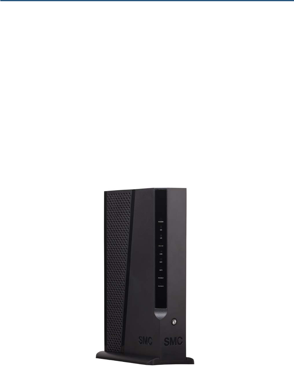
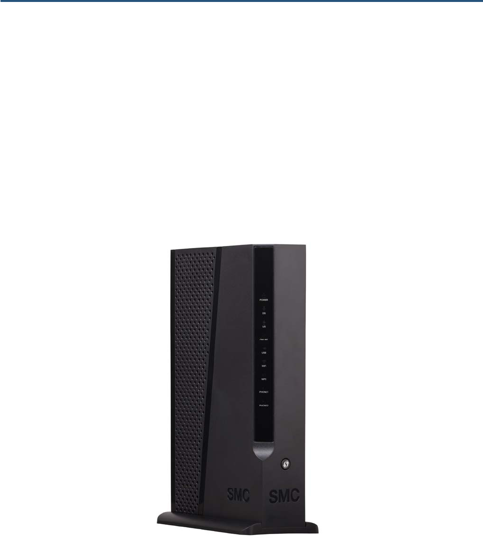
Top Panel
The top panel of your Gateway contains a set of light-emitting diode (LED) indicators. These LEDs
show the status of your Gateway and simplify troubleshooting. Additional LEDs on the rear panel of the
Gateway show link status (see page 5).
Figure 1 shows the top panel of the Gateway. Table 1 describes the top panel LEDs.
Figure 1. Top Panel of the Gateway
4
SMCD3GNV4 and SMCD3GNV4E Wireless EMTA Gateway Administrator Manual
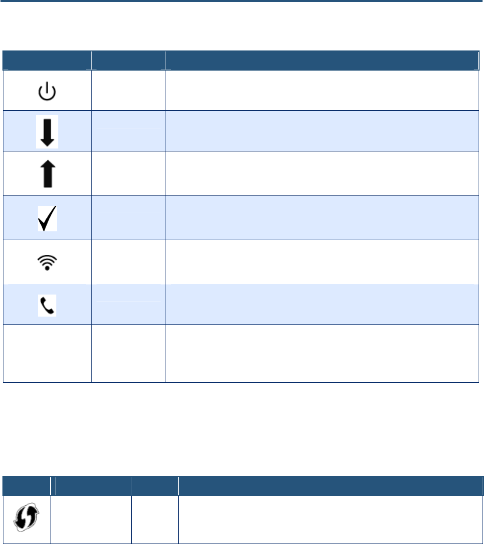
Table 1. Top Panel LEDs
Symbol LED Description
Power ON = power is supplied to the Gateway
OFF = power is not supplied to the Gateway
DS Blinking = scanning for DS channel
ON = ranged on one or more channels
US Blinking = ranging is in progress
ON = ranging is complete on 1 channel only
OFF = scanning for DS channel
Online Blinking = cable interface is acquiring IP, ToD, CM configuration
ON = Gateway is operational
OFF = Gateway is offline
Wi-Fi Blinking = data is transmitting
ON = Wi-Fi is enabled
OFF = Wi-Fi is disabled
PHONE 1/2 Blinking = phone set off-hook
ON = phone set on-hook
LEDs on rear panel
Link Green/Amber blinking = data is transmitting
Green ON = connected at 1 Gbps.
Amber ON = connected at 10 or 100 Mbps
OFF = no Ethernet link detected
Front Panel Push Button
Table 2. Front Panel Push Button
Symbol Function Type Description
WPS Button Press this button to establish a wireless connection between the Gateway and a WPS-enabled
client (see “Configuring WPS Settings” on page 41).
5
SMCD3GNV4 and SMCD3GNV4E Wireless EMTA Gateway Administrator Manual
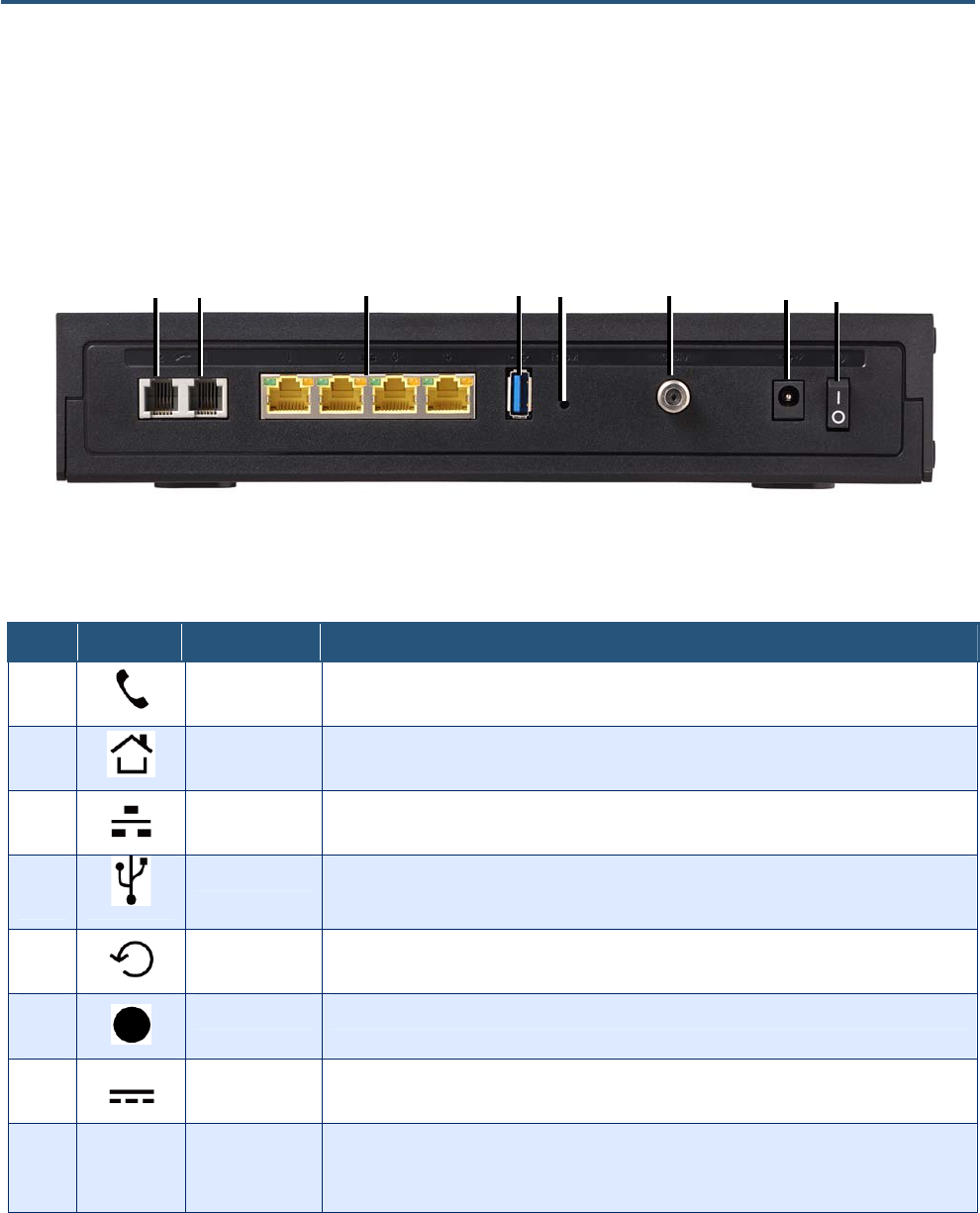
Rear Panel
The rear panel of the Gateway contains a reset button and ports for attaching the supplied power cord
and making other connections. Figure 2 shows the rear panel components and Table 3 describes them.
Figure 2. Rear View of the Gateway
Table 3. Gateway Rear Panel Components
Item Symbol Meaning Description
n
Phone Connect the a telephone set to the Gateway
o
Alarm Connect the Gateway to the phone line outlet.
p
Ethernet 1-4 Four 10/100/1000 auto-sensing RJ-45 switch ports. Connect devices on your local-area network, such
as a computer, hub, or switch, to these ports.
q
USB 3-4 This Gateway provides four USB 2.0 host ports, two (USB3-4) on the rear panel and two (USB1-2) on
the Expansion Slot on the bottom of the Gateway. Use these ports to connect to USB printers, hard
drives, and other peripherals.
r
Reset Use this button to reboot the Gateway or restore the default factory settings (see Chapter 6 “Resetting
and Rebooting the Gateway”). This button is recessed to prevent accidental resets of your Gateway.
s
Cable Connect your coaxial cable line to this port.
t
Power Connect the supplied power adapter to this port.
u
ON/OFF Switch Turns the Gateway ON or OFF.
ξ = Press to turn ON the Gateway.
μ = Press to turn OFF the Gateway.
n o p q r s t u

6
SMCD3GNV4 and SMCD3GNV4E Wireless EMTA Gateway Administrator Manual
Resetting or Rebooting the Gateway
You can use the Reset button on the Gateway rear panel to power cycle the Gateway or reset the
Gateway to its original factory default settings.
Note: You can also reset or reboot the Gateway using the Restore/Reboot page (see page
100).
Rebooting the Gateway
To reboot the Gateway and keep any customized overrides you made to the default settings:
1. Leave power cord connected to the Gateway.
2. Press and hold the Reset button on the Gateway back panel for about 10 seconds, then release the
Reset button.
3. Wait for the Gateway to reboot.
Restoring Factory Defaults
To reset the Gateway to its original factory default settings:
1. Leave power plugged into the Gateway.
2. Press and hold the Reset button on the Gateway back panel for about 15 seconds, then release the
Reset button.
3. Wait for the Gateway to reboot with factory default settings.

7
SMCD3GNV4 and SMCD3GNV4E Wireless EMTA Gateway Administrator Manual
2 Installing Your Gateway
This chapter describes how to install the Gateway. The topics covered in this chapter are:
y Finding a Suitable Location (page 8)
y Connecting to the LAN (page 9)
y Connecting the WAN (page 10)
y Powering on the Gateway (page 10)

8
SMCD3GNV4 and SMCD3GNV4E Wireless EMTA Gateway Administrator Manual
Finding a Suitable Location
You can install the Gateway in any location with access to the cable network. All of the cables connect
to the rear panel of the Gateway for better organization and utility. The LED indicators on the front panel
are easily visible to provide you with information about network activity and status.
For optimum performance, the location you choose should:
y Be close to a working AC power outlet
y Allow sufficient air flow around the Gateway to keep the device as cool as possible
y Not expose the Gateway to a dusty or wet environment
y Be an elevated location such as a high shelf, keeping the number of walls and ceilings between the
Gateway and your other devices to a minimum
y Be away from electrical devices that are potential sources of interference, such as ceiling fans,
home security systems, microwaves, or the base for a cordless phone
y Be away from any large metal surfaces, such as a solid metal door or aluminum studs. Large
expanses of other materials such as glass, insulated walls, fish tanks, mirrors, brick, and concrete
can also affect your wireless signal.
9
SMCD3GNV4 and SMCD3GNV4E Wireless EMTA Gateway Administrator Manual
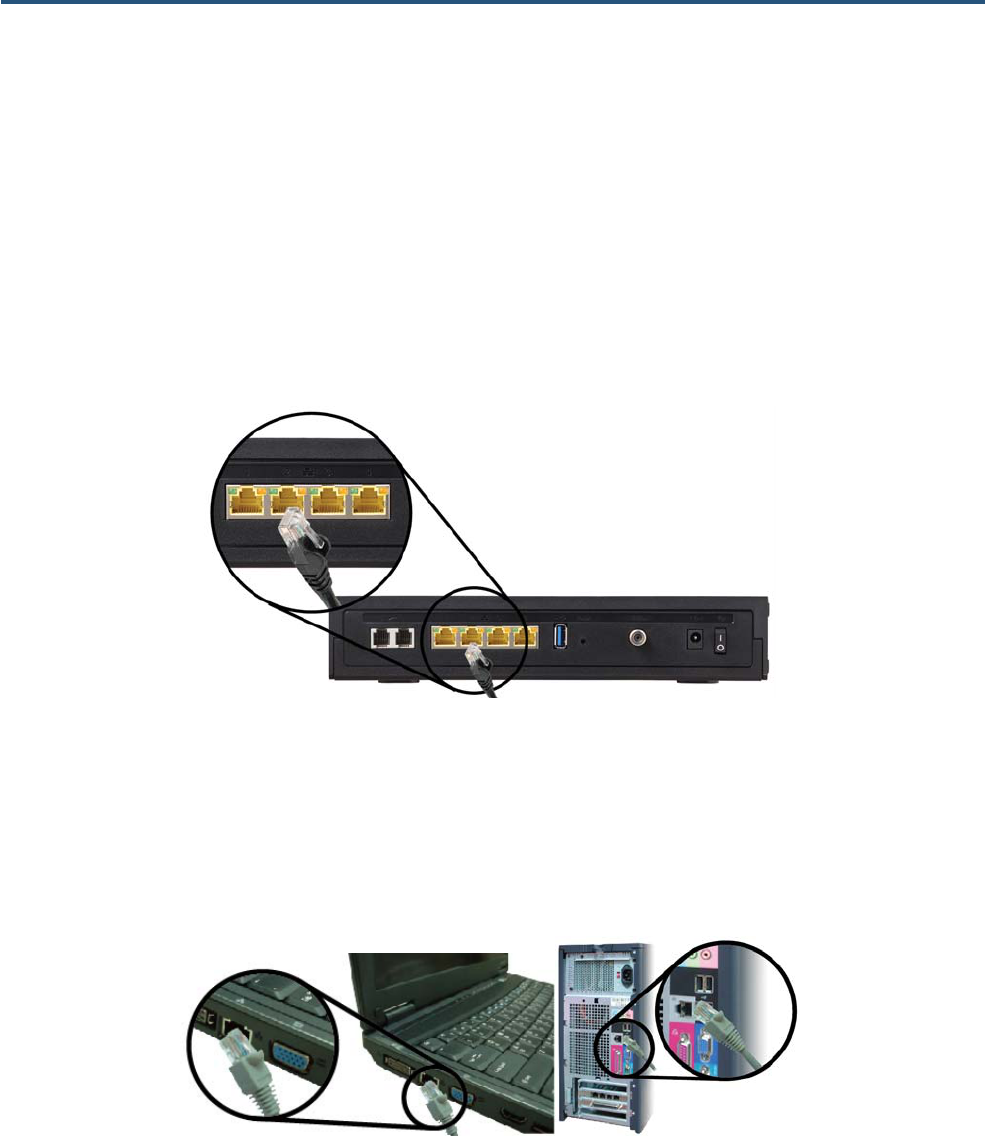
Connecting to the LAN
Using an Ethernet LAN cable, you can connect the Gateway to a desktop computer, notebook, hub, or
switch. The Gateway supports auto-MDI/MDIX, so you can use either a standard straight-through or
crossover Ethernet cable.
4. Connect either end of an Ethernet cable to one of the four LAN ports on the rear panel of the
Gateway (see Figure 3).
Figure 3. Connecting to a LAN Port on the Gateway Rear Panel
5. Connect the other end of the cable to your computer’s network-interface card (NIC) or to another
network device (see Figure 4).
Figure 4. Connecting the Gateway to the a Laptop or Desktop Computer

10
SMCD3GNV4 and SMCD3GNV4E Wireless EMTA Gateway Administrator Manual
Connecting the WAN
To connect your Gateway to a Wide Area Network (WAN) interface:
6. Connect a coaxial cable from a cable port in your home or office to the port labeled Cable/MoCA on
the rear panel of the Gateway (see Figure 2 on page 5). Use only manufactured coaxial patch cables
with F-type connectors at both ends for all connections.
7. Hand-tighten the connectors to secure the connection.
8. If the modem was not installed by your cable provider (ISP) or is replacing another cable modem,
contact your cable operator to register the Gateway. If the modem is not registered with your cable
operator, it will not be able to connect to the cable network system.
Powering on the Gateway
After making your LAN and WAN connections, use the following procedure to power on the Gateway:
1. Connect the supplied power cord to the port labeled Power on the rear panel of the Gateway (see
Figure 2 on page 5).
2. Connect the other end of the power cord to a working power outlet. The Gateway powers on
automatically. The Power LED on the Gateway front panel goes ON and the other front panel LEDs
show the Gateway’s status (see Table 1 on page 4).
WARNING: Only use the power cord supplied with the Gateway. Using a different power cord
can damage your Gateway and void the warranty.

11
SMCD3GNV4 and SMCD3GNV4E Wireless EMTA Gateway Administrator Manual
3 Preparing to Configure Your Gateway
Before you can access the Gateway’s GUI, configure the TCP/IP settings in your computer’s operating
system that will be used to configure the Gateway. The topics covered in this chapter are:
y Configuring Microsoft Windows 2000 - see page 12
y Configuring Microsoft Windows XP - see page 13
y Configuring Microsoft Windows Vista - see page 14
y Configuring an Apple® Macintosh® Computer – see page 16
12
SMCD3GNV4 and SMCD3GNV4E Wireless EMTA Gateway Administrator Manual
Configuring Microsoft Windows 2000
Use the following procedure to configure your computer if your computer has Microsoft Windows 2000
installed.
1. On the Windows taskbar, click Start, point to Settings, and then click Control Panel.
2. In the Control Panel window, double-click the Network and Dial-up Connections icon. If the
Ethernet adapter in your computer is installed correctly, the Local Area Connection icon appears.
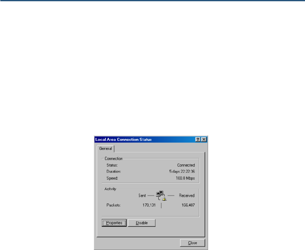
3. Double-click the Local Area Connection icon for the Ethernet adapter connected to the Gateway.
The Local Area Connection Status dialog box appears (see Figure 5).
Figure 5. Local Area Connection Status Window
4. In the Local Area Connection Status dialog box, click the Properties button. The Local Area
Connection Properties dialog box appears.
5. In the Local Area Connection Properties dialog box, verify that Internet Protocol (TCP/IP) is
checked. Then select Internet Protocol (TCP/IP) and click the Properties button.
6. Click Obtain an IP address automatically to configure your computer for DHCP.
7. Click the OK button to save this change and close the Local Area Connection Properties dialog box.
8. Click OK button again to save these new changes.
9. Restart your computer.
13
SMCD3GNV4 and SMCD3GNV4E Wireless EMTA Gateway Administrator Manual
Configuring Microsoft Windows XP
Use the following procedure to configure a computer running Microsoft Windows XP with the default
interface. If you use the Classic interface, where the icons and menus resemble previous Windows
versions, perform the procedure under “Configuring Microsoft Windows 2000”.
1. On the Windows taskbar, click Start, click Control Panel, and then click Network and Internet
Connections.
2. Click the Network Connections icon.
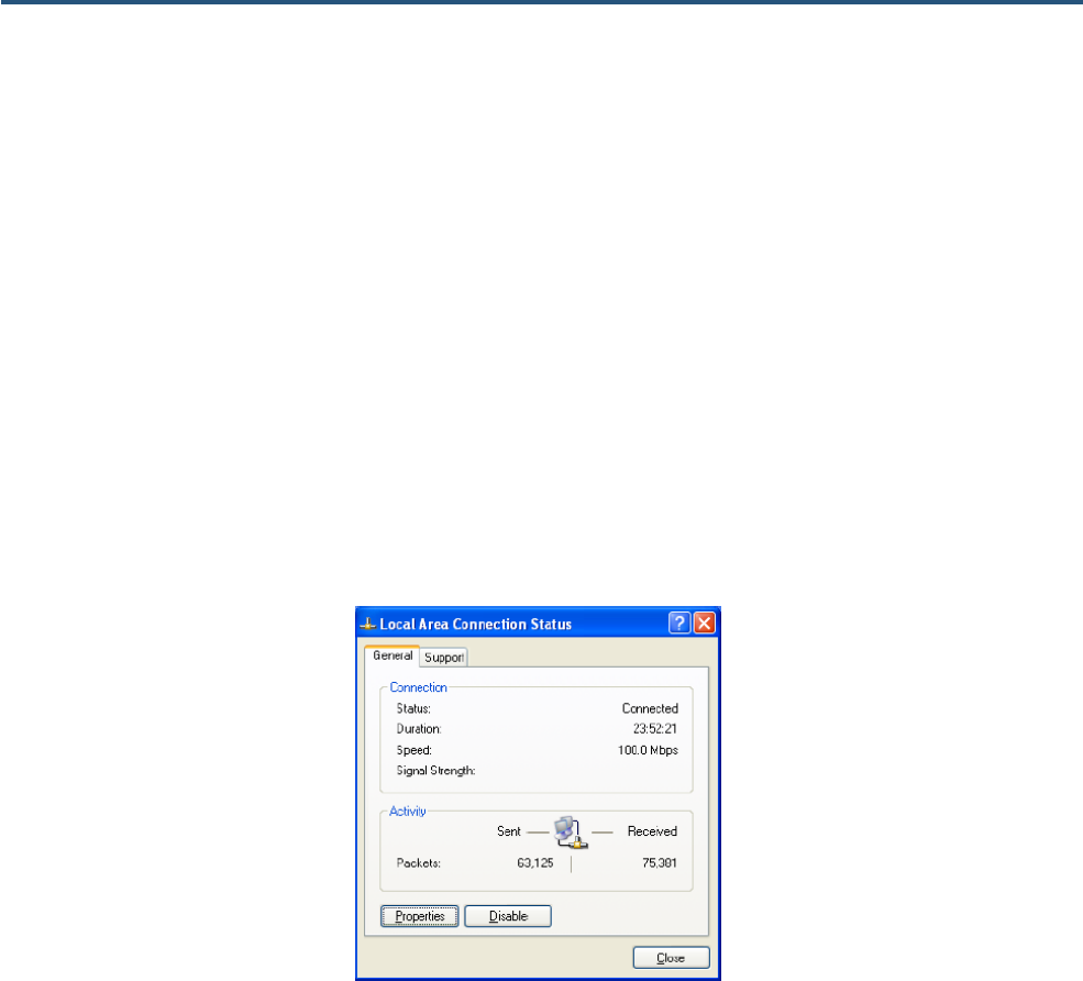
3. Double-click Local Area Connection for the Ethernet adapter connected to the Gateway. The Local
Area Connection Status dialog box appears.
4. In the Local Area Connection Status dialog box, click the Properties button (see Figure 6). The
Local Area Connection Properties dialog box appears.
Figure 6. Local Area Connection Status Window
5. In the Local Area Connection Properties dialog box, verify that Internet Protocol (TCP/IP) is
checked. Then select Internet Protocol (TCP/IP) and click the Properties button. The Internet
Protocol (TCP/IP) Properties dialog box appears.
6. In the Internet Protocol (TCP/IP) Properties dialog box, click Obtain an IP address automatically
to configure your computer for DHCP. Click the OK button to save this change and close the Internet
Protocol (TCP/IP) Properties dialog box.
7. Click the OK button again to save your changes and restart your computer.
14
SMCD3GNV4 and SMCD3GNV4E Wireless EMTA Gateway Administrator Manual
Configuring Microsoft Windows Vista
Use the following procedure to configure a computer running Microsoft Windows Vista with the default
interface. If you use the Classic interface, where the icons and menus resemble previous Windows
versions, perform the procedure under “Configuring Microsoft Windows 2000”.
1. On the Windows taskbar, click Start, click Control Panel, and then select Network and Internet
Icon.
2. Click View Networks Status and tasks and then click Management Networks Connections.
3. Right-click the Local Area Connection icon and click Properties.
4. Click Continue. The Local Area Connection Properties dialog box appears.
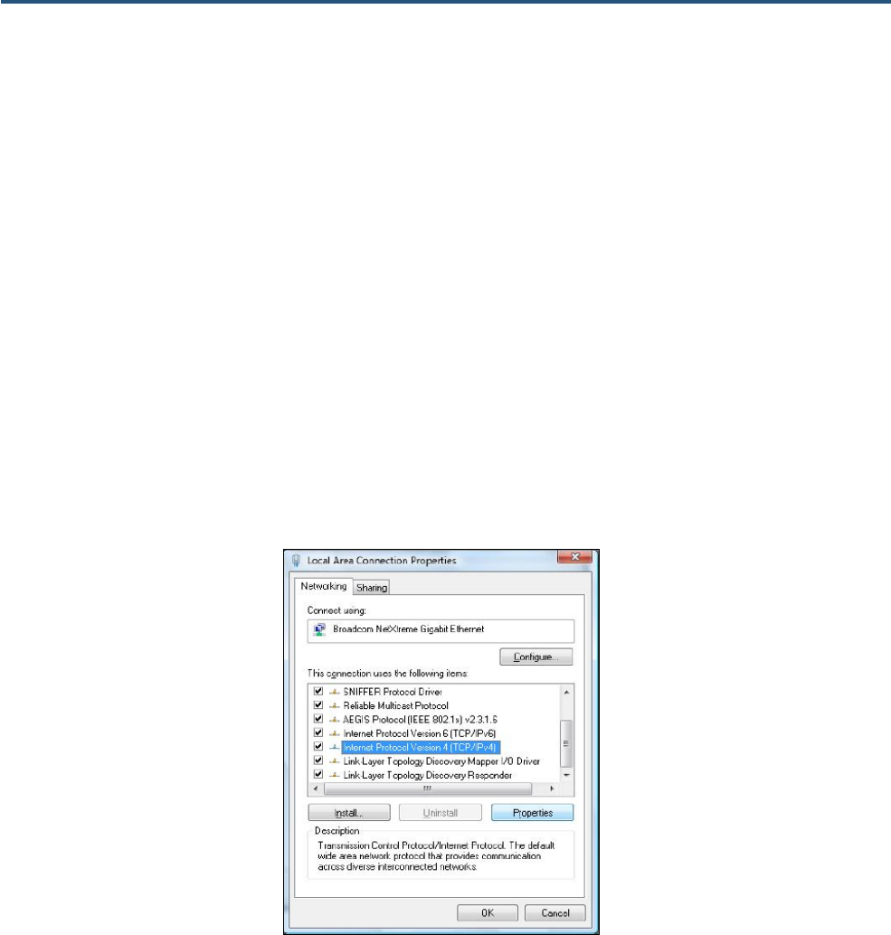
5. In the Local Area Connection Properties dialog box, verify that Internet Protocol (TCP/IPv4) is
checked. Then select Internet Protocol (TCP/IPv4) and click the Properties button (see Figure 7).
The Internet Protocol Version 4 Properties dialog box appears.
Figure 7. Local Area Connection Properties Window
15
SMCD3GNV4 and SMCD3GNV4E Wireless EMTA Gateway Administrator Manual
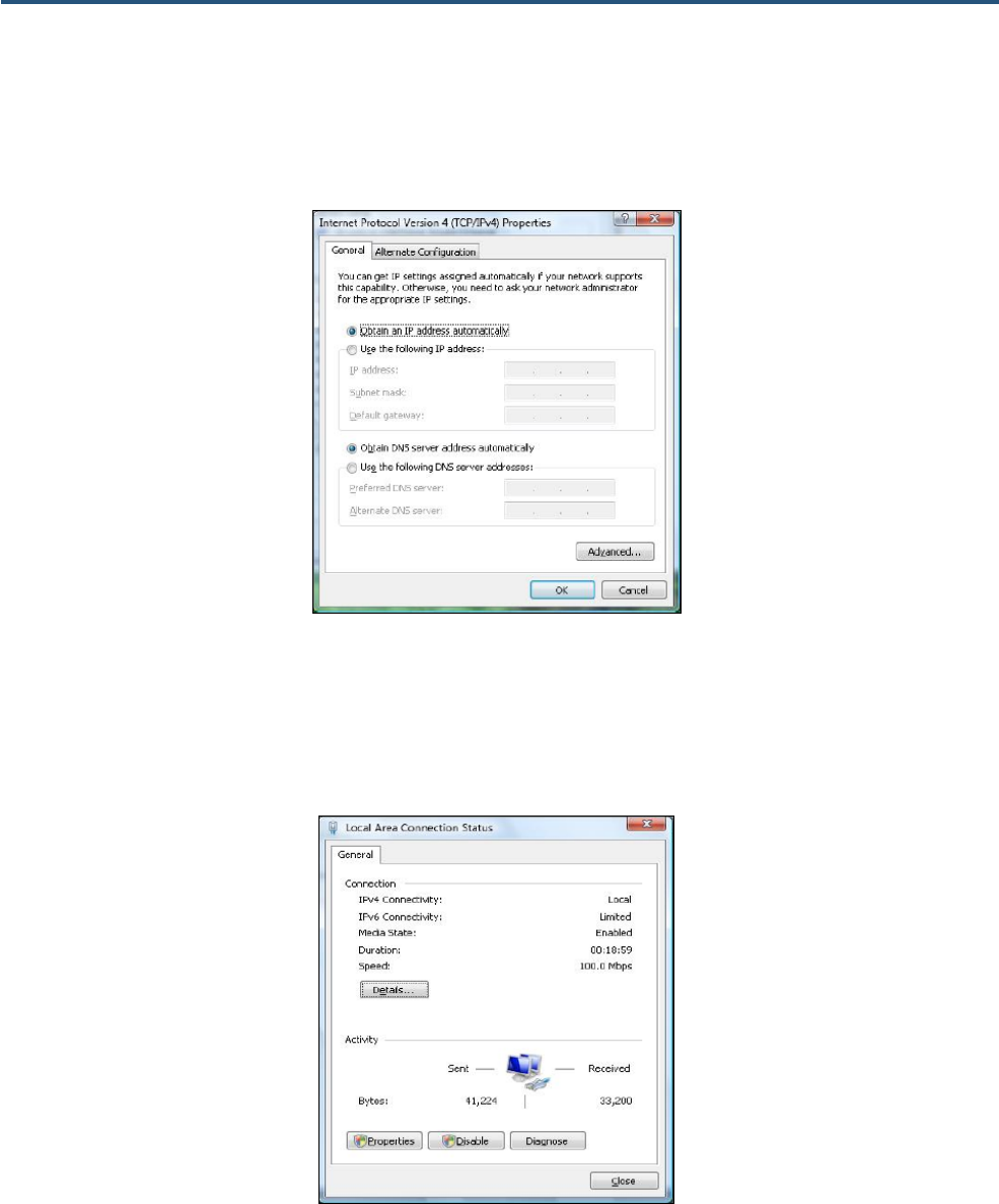
6. In the Internet Protocol Version 4 Properties dialog box, click Obtain an IP address automatically
to configure your computer for DHCP (see Figure 8).
Figure 8. Internet Protocol Properties Window
7. Click the OK button to save your changes and close the dialog box.
8. Click the OK button again to save your changes (see Figure 9).
Figure 9. Local Area Connection Status Window
16
SMCD3GNV4 and SMCD3GNV4E Wireless EMTA Gateway Administrator Manual
Configuring an Apple® Macintosh® Computer
The following procedure describes how to configure TCP/IP on an Apple Macintosh running Mac OS
10.2. If your Apple Macintosh is running Mac OS 7.x or later, the steps you perform and the screens you
see may differ slightly from the following. However, you should still be able to use this procedure as a
guide to configuring your Apple Macintosh for TCP/IP.
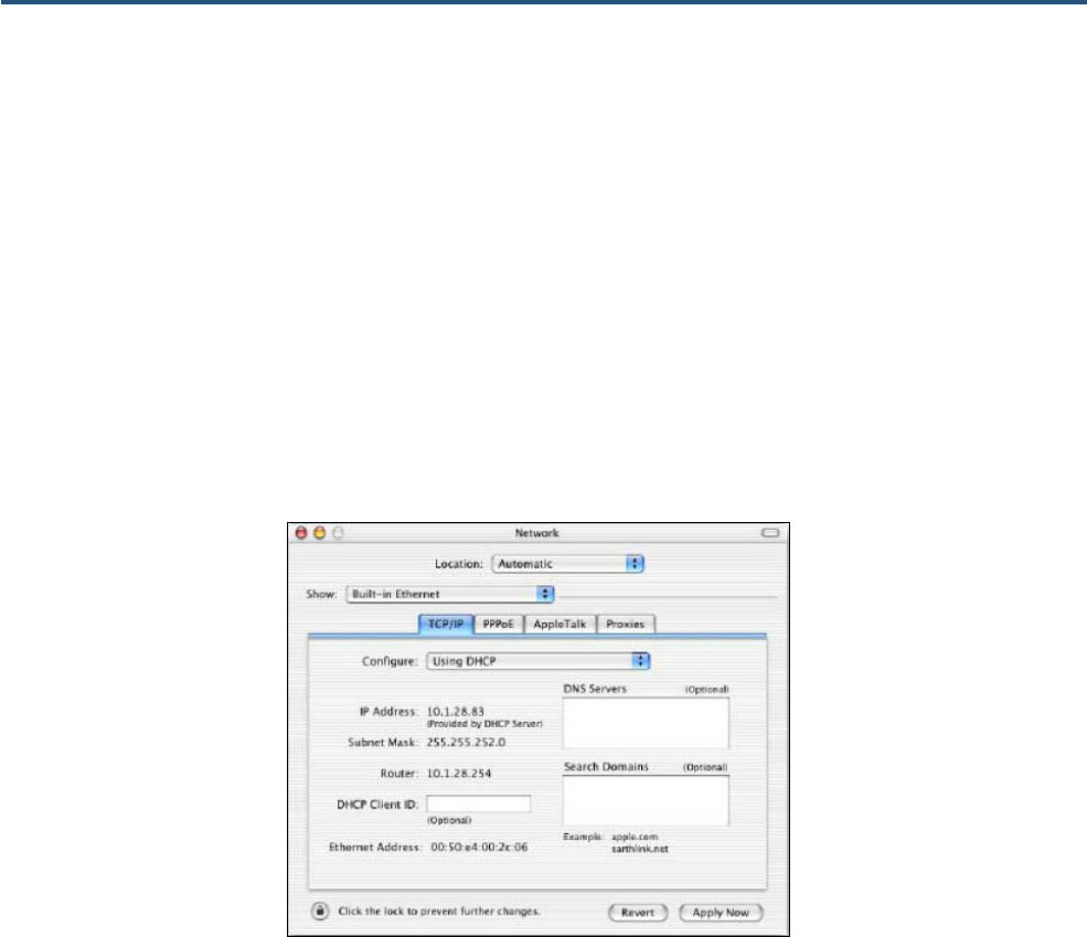
1. Pull down the Apple Menu, click System Preferences, and select Network.
2. Verify that NIC connected to the Gateway is selected in the Show field.
3. In the Configure field on the TCP/IP tab, select Using DHCP (see Figure 10).
4. Click Apply Now to apply your settings and close the TCP/IP dialog box.
Figure 10. Selecting Using DHCP in the Configure Field

17
SMCD3GNV4 and SMCD3GNV4E Wireless EMTA Gateway Administrator Manual
Disabling Proxy Settings
Before using the Gateway GUI, disable proxy settings in your Web browser. Otherwise, you will not be
able to view the Gateway’s Web-based configuration pages.
Disabling Proxy Settings in Internet Explorer
The following procedure describes how to disable proxy settings in Internet Explorer 5 and later.
1. Start Internet Explorer.
2. On your browser’s Tool menu, click Options. The Internet Options dialog box appears.
3. In the Internet Options dialog box, click the Connections tab.
4. In the Connections tab, click the LAN settings button. The Local Area Network (LAN) Settings
dialog box appears.
5. In the Local Area Network (LAN) Settings dialog box, uncheck all check boxes.
6. Click OK until the Internet Options window appears.
7. In the Internet Options window, under Temporary Internet Files, click Settings.
8. For the option Check for newer versions of stored pages, select Every time I visit the webpage.
9. Click OK until you close all open browser dialog boxes.
Disabling Proxy Settings in Firefox
The following procedure describes how to disable proxy settings in Firefox.
1. Start Firefox.
2. On your browser’s Tools menu, click Options. The Options dialog box appears.
3. Click the Advanced tab.
4. In the Advanced tab, click the Network tab.
5. Click the Settings button.
6. Click Direct connection to the Internet.
7. Click the OK button to confirm this change.

18
SMCD3GNV4 and SMCD3GNV4E Wireless EMTA Gateway Administrator Manual
Disabling Proxy Settings in Safari
The following procedure describes how to disable proxy settings in Safari.
1. Start Safari.
2. Click the Safari menu and select Preferences.
3. Click the Advanced tab.
4. In the Advanced tab, click the Change Settings button.
5. Choose your location from the Location list (this is generally Automatic).
6. Select your connection method. If using a wired connection, select Built-in Ethernet. For wireless,
select Airport.
7. Click the Proxies tab.
8. Be sure each proxy in the list is unchecked.
9. Click Apply Now to finish.
Disabling Firewall and Security Software
Before configuring the Gateway using the Gateway GUI, disable any firewall or security software that
may be running on your computer. For more information, refer to the documentation for your firewall.
Confirming Your Gateway’s Link Status
Before configuring the Gateway using the Gateway GUI, confirm that the Ethernet Port’s LED on the
rear panel of the Gateway panel is ON. If the LED is OFF, replace the Ethernet cable connecting your
computer and Gateway.

19
SMCD3GNV4 and SMCD3GNV4E Wireless EMTA Gateway Administrator Manual
4 Configuring the Gateway
To configure the Gateway’s user settings, prepare your computer as described in Chapter 3. Then use
the information in this chapter to configure the Gateway’s user settings.
The topics covered in this chapter are:
y Logging in to the Gateway’s Web Management Interface (page 20)
y Understanding the Web Management Interface Screens (page 21)
y Web Management Interface Menus (page 23)
20
SMCD3GNV4 and SMCD3GNV4E Wireless EMTA Gateway Administrator Manual
Logging in to the Gateway’s Web Management Interface
To access the Gateway’s configuration settings, launch a Web browser (Microsoft Internet Explorer or
Netscape Navigator, versions 5.0 or later) on the computer you configured in Chapter 3 and log in to the
Gateway’s admin interface.
To access the Gateway’s admin configuration settings, use the following procedure.
1. Launch a Web browser.
Note: Your computer does not have to be online to configure your Gateway.
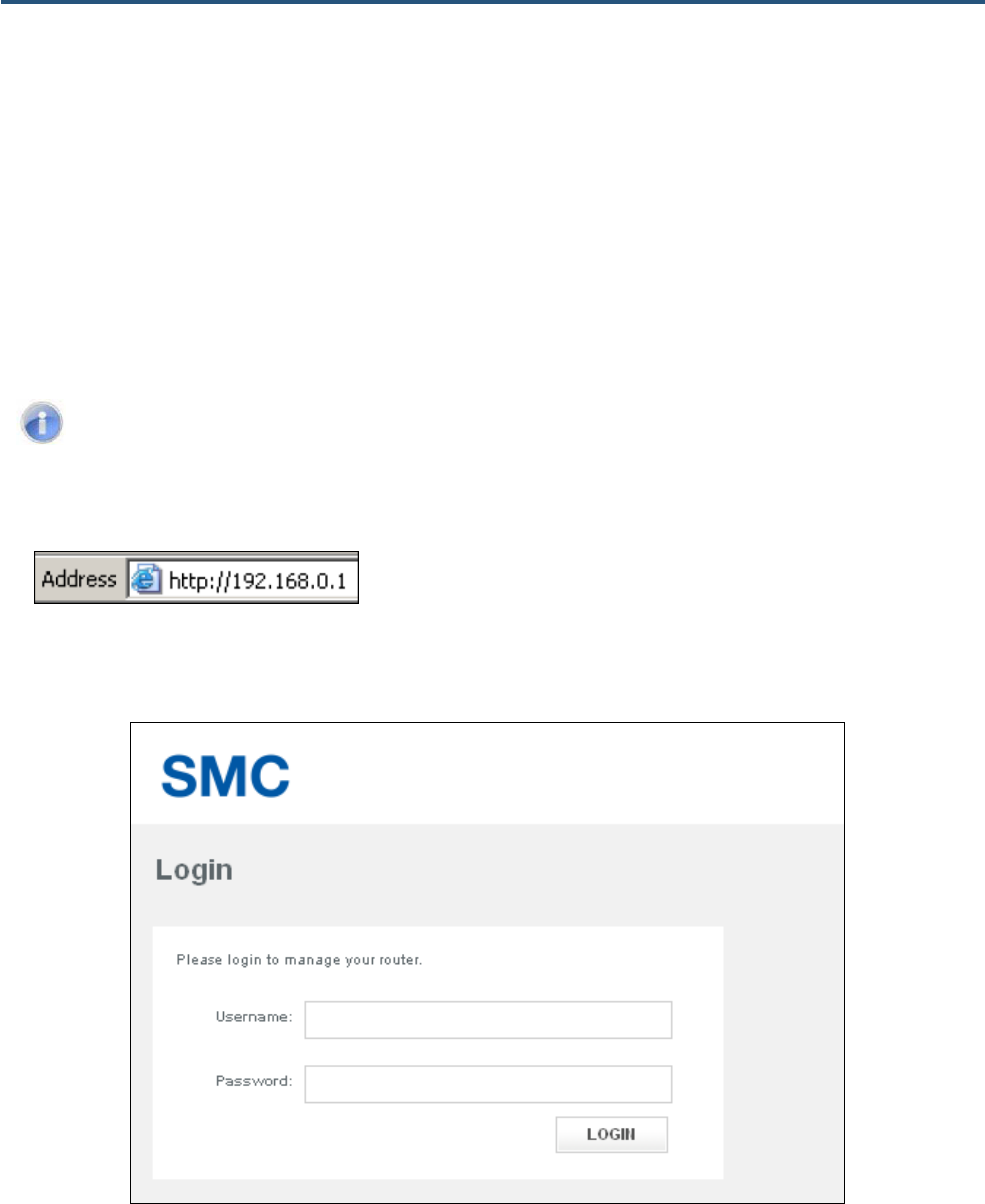
2. In the browser address bar, type http://192.168.0.1 and press the Enter key. For example:
The Login screen appears (see Figure 11).
Figure 11. Login Screen
21
SMCD3GNV4 and SMCD3GNV4E Wireless EMTA Gateway Administrator Manual
3. In the Login screen, enter the default user username and the default user password provided by
SMC. Both the username and password are case sensitive.
4. Click the LOGIN button to access the Gateway. The Web management interface starts and Step 1 of
the Home Network Wizard appears (see page 52).
Tip: After you log in to the Web management interface, we recommend you change the default
password on the Troubleshooting > Change Password page (see page 95).
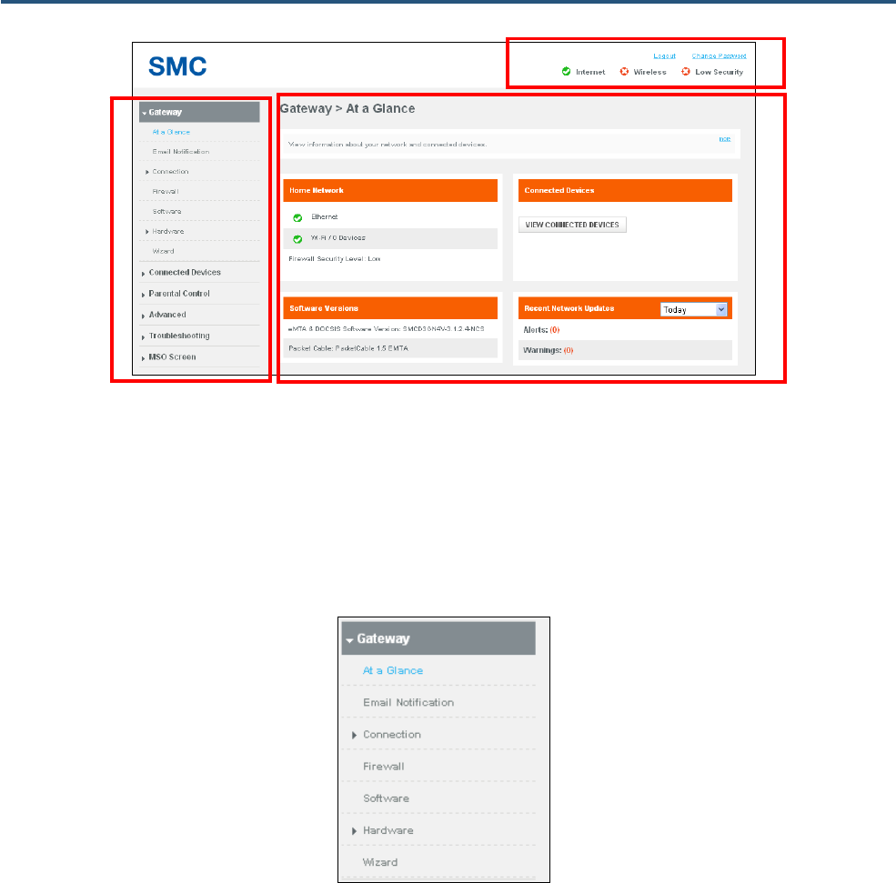
Understanding the Web Management Interface Screens
The left side of the management interface contains a menu bar for you to configure the Gateway. When
you click a menu, information and any configuration settings associated with the menu appear in the
main area of the interface (see Figure 13). If the displayed information exceeds that can be shown in the
main area, scroll bars appear to the right of the main area so you can scroll up and down through the
information.
The top of the main area shows the path (or “breadcrumbs”) associated with the information displayed
in the main area. For example, if you click the Gateway menu, Gateway > At a Glance appears at the
top of the main area.
The top-right area shows links for changing the login password and logging out of your current session.
Below the links are status icons that show the:
y Gateway’s Internet access
y Status of the Gateway’s wireless connection
y Custom security level
Moving the mouse over the Internet, Wireless, and Security level icons displays additional
information. For example, hovering your mouse pointer over Internet displays the number of active
computers connected to the Gateway (see Figure 12).
Figure 12. Example of Hovering Over the Internet Icon
22
SMCD3GNV4 and SMCD3GNV4E Wireless EMTA Gateway Administrator Manual
Figure 13. Main Areas on the Web Management Interface
All menus have submenus associated with them. If you click a menu, the submenus appear below it.
For example, if you click the Gateway menu, the submenus At a Glance, Email Notification,
Connection, Firewall, Software, Hardware, and Wizard appear below the Gateway menu (see
Figure 14).
Figure 14. Example of Gateway Submenus
Menu Bar
Main Area
Quick
Information
23
SMCD3GNV4 and SMCD3GNV4E Wireless EMTA Gateway Administrator Manual
Web Management Interface Menus
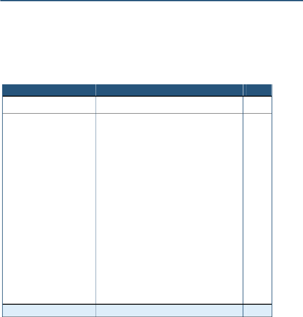
Table 4 describes the pages in the Web management interface.
Table 4. Web Management Interface Menus and Submenus
Menus and Submenus Description See Page
Gateway > At a Glance Reports information about your network, connected devices, software
versions, and recent network updates. 26
Gateway > Email Notification Lets you configure the Gateway to send email notifications when there is
a firewall breach, parental control breach, alerts or warnings, or a request
is made to send logs to a destination.
27
Gateway > Connection > Status Lets you edit settings for the local IP network, and view the settings of the
Wi-Fi network and XFINITY network. 27
Gateway > Connection > Local IP Network Reports the Gateway IP address, subnet mask, and DHCP addresses
and lease time. 31
Gateway > Connection > Public Lan Configures static IP addressing for the Gateway. 33
Gateway > Connection > WiFi Reports technical information specific to your Wi-Fi connection. 35
Gateway > Connection > WAN Reports technical information about the Wide Area Network, cable
modem, and downstream and upstream bonding values. 43
Gateway > Firewall Configures the security level of the Gateway’s internal firewall. 45
Gateway > Software Reports system software and handset software information. 47
Gateway > Hardware > System Hardware Reports information about the Gateway system hardware. 48
Gateway > Hardware > LAN Reports link status and MAC address of the Gateway’s four Gigabit
Ethernet LAN ports. 49
Gateway > Hardware > Wireless Reports connection status and MAC address of the wireless network. 50
Gateway > Hardware> USB Reports status information about USB devices connected to the
Gateway. 51
Gateway > Wizard Runs the Home Network wizard to help you set up a home network. 52
Connected Devices > Computers Reports computers connected to the Gateway's LAN. 56
24
SMCD3GNV4 and SMCD3GNV4E Wireless EMTA Gateway Administrator Manual
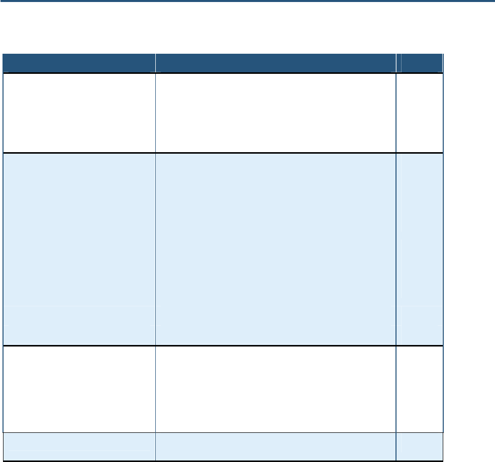
Table 4. Web Management Interface Menus and Submenus
Menus and Submenus Description See Page
Parental Control > Managed Sites Configures blocked sites, blocked keywords, and trusted computers. 59
Parental Control > Managed Services Configures blocked services and trusted computers. 64
Parental Control > Managed Devices Configures managed and blocked devices. 67
Parental Control > Reports Generates, prints, and downloads reports based on user-defined criteria. 71
Advanced > Port Forwarding Enables or disables the Gateway’s port forwarding feature. 74
Advanced > Port Triggering Enables or disables the Gateway’s port triggering feature. 77
Advanced > Remote Management Configures the ways in which the Gateway can be managed remotely. 80
Advanced > Routing Configure the Routing Information Protocol (RIP) used by the Gateway to
exchange routing information with the headend 82
Advanced > DMZ Configures a computer for unrestricted two-way Internet access. 80
Advanced > QoS Configures the Gateway to deliver better resource reservation control. 85
Advanced > Device Discovery Enables or disables the Gateway’s Universal Plug and Play (UPnP)
feature for dynamic connectivity to devices on the network. 87
Advanced > VPN > VPN Global Enables or disables the Gateway’s VPN settings 89
Advanced > VPN > IPSEC Tunnel Configure Internet Protocol Security (IPsec) tunnels on the Gateway. 91
Troubleshooting > Logs Generates, prints, and downloads reports based on user-defined criteria. 97
Troubleshooting > Diagnostic Tools Tests connectivity to an IP address. 98
Troubleshooting > Restore/Reboot Reboots the Gateway, reboots the Wi-Fi router only, restores Wi-Fi
settings only, or restores factory settings. 100
Troubleshooting > Change Password Changes the password used to log in to the Gateway’s Web interface. 101
MSO Screen Provides access to configuration screens that show basic hardware
information, Event Log, basic WAN information, and DHCP information. 102

25
SMCD3GNV4 and SMCD3GNV4E Wireless EMTA Gateway Administrator Manual
Gateway Page
The Gateway page lets you:
y View at-a-glance information about the Gateway – see page 26.
y Configure the Gateway to send email notifications – see page 27.
y View connection status – see page 29.
y Configure the local IP settings for your home network – see page 31.
y Configure static IP address information for the Gateway and enable the Gateway to use static IP
addressing – see page 33.
y Configure WiFi settings – see page 35.
y View information about the Wide Area Network, cable modem, and downstream and upstream
bonding values.– see page 43.
y Configure firewall settings – see page 45.
y View system software information – see page 47.
y View hardware information – see page 48.
y View information about the Gateway’s four Gigabit Ethernet LAN ports – see page 49.
y View 2.4 GHz and 5GHz information about the Gateway – see page 50.
y View the status of USB devices connected to the Gateway – see page 51.
y Run the Home Network wizard to set up your network – see page 52.
26
SMCD3GNV4 and SMCD3GNV4E Wireless EMTA Gateway Administrator Manual
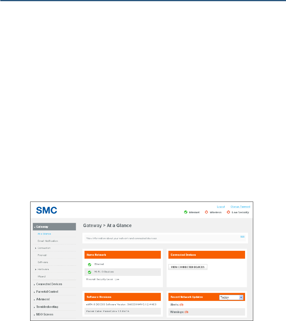
At a Glance Page
Path: Gateway > At a Glance
The At a Glance page shows information about your network and connected devices.
The At a Glance page is organized into four areas:
y Home Network shows the connection status of Ethernet, wireless and firewall security level.
y Connected Devices shows the device that is currently connected to the Gateway. A View
Connected Devices button opens the Computers page for viewing devices that the Gateway
automatically detects using DHCP (see page 56).
y Software Versions shows the software version number of the system, including eMTA and
DOCSIS, DECT, Advanced Services, and Packet Cable.
y Recent Network Updates shows alerts and warnings issued by the Gateway. A drop-down list lets
you select updates from today, yesterday, last week, last month, and the last 90 days. Updates that
exceed one month are purged by the Gateway automatically.
Figure 15. At a Glance Page
27
SMCD3GNV4 and SMCD3GNV4E Wireless EMTA Gateway Administrator Manual
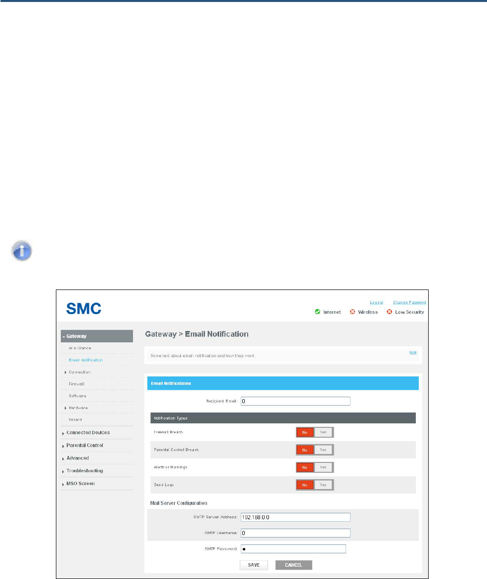
Email Notifications Page
Path: Gateway > Email Notification
The Email Notification page lets you configure the Gateway to send email notifications automatically
when one or ore of the following events occurs:
y Firewall breach
y Parental control breach
y Alerts or warnings
y A request is made to send logs to a destination
Note: This configuration assumes that the Simple Mail Transfer Protocol (SMTP) mail server
the Gateway will use is configured and operating properly.
Figure 16. Email Notification Page
28
SMCD3GNV4 and SMCD3GNV4E Wireless EMTA Gateway Administrator Manual
Table 5. Email Notification Page Options
Option Description
Recipient Email Enter the email address of the recipient to whom the Gateway will send email notifications.
Notification Types The gateway can be configured to send email for four types of notifications:
• Firewall Breach = an attempt was made top breach the firewall.
• Parental Control Breach = an attempt was made to breach a parental control.
• Alerts or Warnings = an alert or warning occurred that requires attention.
• Send Logs = an attempt was made to send the Gateway logs to a destination.
By default, the Gateway is configured to not send email notifications for these types of notifications. For each notification
you want to be informed about, click Yes next to that notification type..
Mail Server Configuration Enter the settings for your SMTP mail server. This configuration assumes that your SMTP server is configured and
operating properly.
• SMTP Server Address = enter the domain name or IP address of the SMTP server.
• SMTP Username = enter the user name required to connect to the SMMPT server.
• SMTP Password = enter the password required to connect to the SMMPT server. For security, each typed password
character is masked with a dot (λ).

29
SMCD3GNV4 and SMCD3GNV4E Wireless EMTA Gateway Administrator Manual
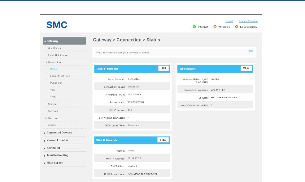
Status Page
Path: Gateway > Connection > Status
The Status page is a read-only page that displays information about the Gateway’s connection status.
The Status page is organized into three areas:
y Local IP Network shows the local IP network status, connection speed, IPv4 address and subnet
mask, DHCP server status, number of clients connected, and DHCP lease time. Click the EDIT
button to view and edit local IP configuration settings (see “Local IP Configuration Page” on page
31).
y WiFi Network shows the wireless network status, supported protocols, security type, and number
of connected wireless clients. Click the VIEW button to view Wi-Fi LAN port and DECT base
information (see “Wireless Hardware Info Page” on page 50).
y WAN IP Network shows the Internet connection status, the obtained WAN IP address, DHCP client
status, and DHCP expiration time. Click the VIEW button to view detailed information about the
Wide Area Network (see “WAN Page” on page 43).
30
SMCD3GNV4 and SMCD3GNV4E Wireless EMTA Gateway Administrator Manual
Figure 17. Status Page
31
SMCD3GNV4 and SMCD3GNV4E Wireless EMTA Gateway Administrator Manual
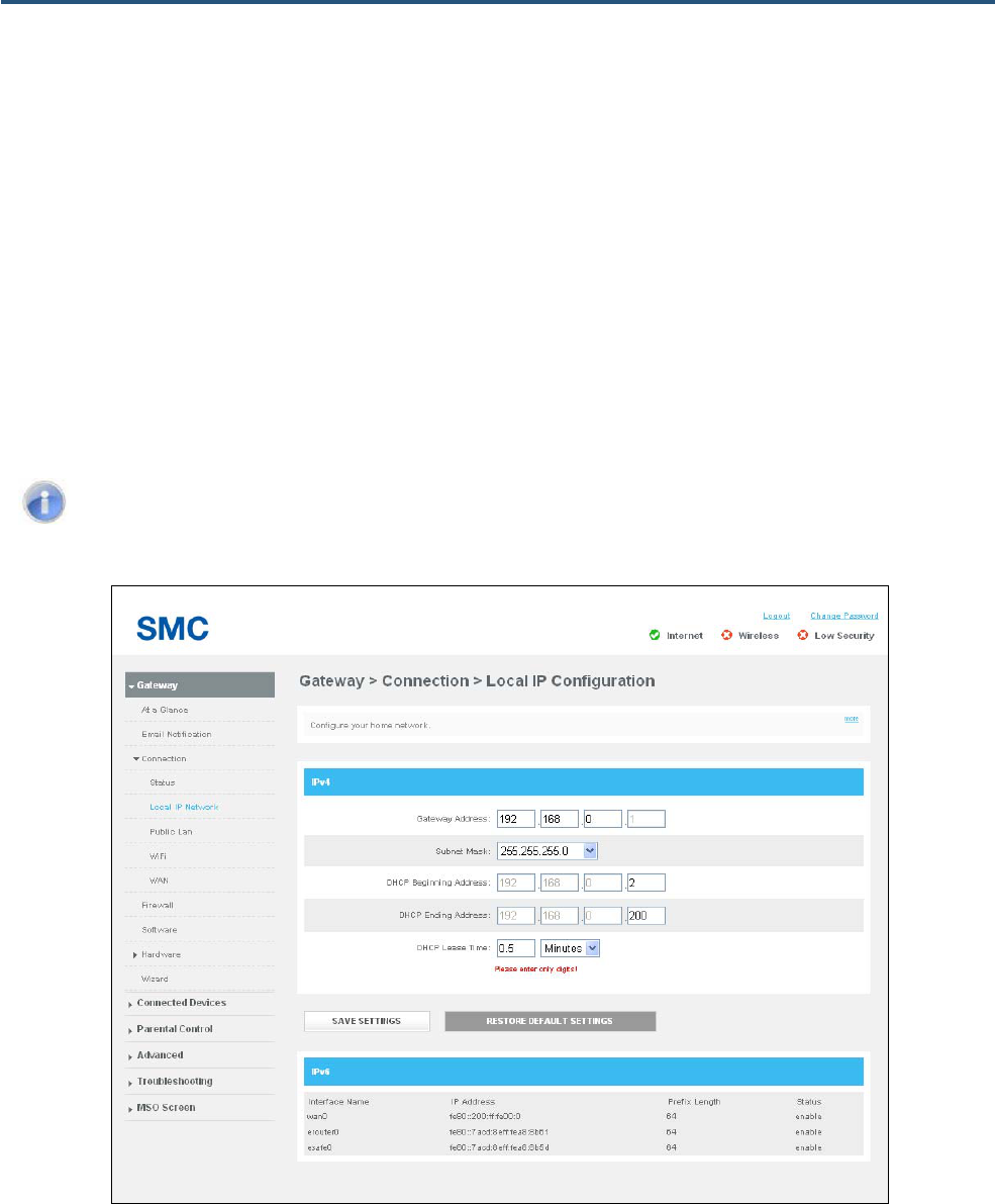
Local IP Configuration Page
Path: Gateway > Connection > Local IP Network
The Local IP Configuration page lets you configure your local network.
The Local IP Configuration page is organized into two areas:
y IPV4 shows the Gateway’s IPv4 settings and allows you to change them to suit your requirements.
Buttons are provided for saving any settings you change or for restoring default settings. Changes
you make are not applied until you click SAVE SETTINGS.
y IPv6 is a read-only section that shows the Gateway’s IPv6 settings.
Note: This page is also available from the Status page by clicking the VIEW button in the Local
IP Network area.
Figure 18. Local IP Configuration Page
32
SMCD3GNV4 and SMCD3GNV4E Wireless EMTA Gateway Administrator Manual
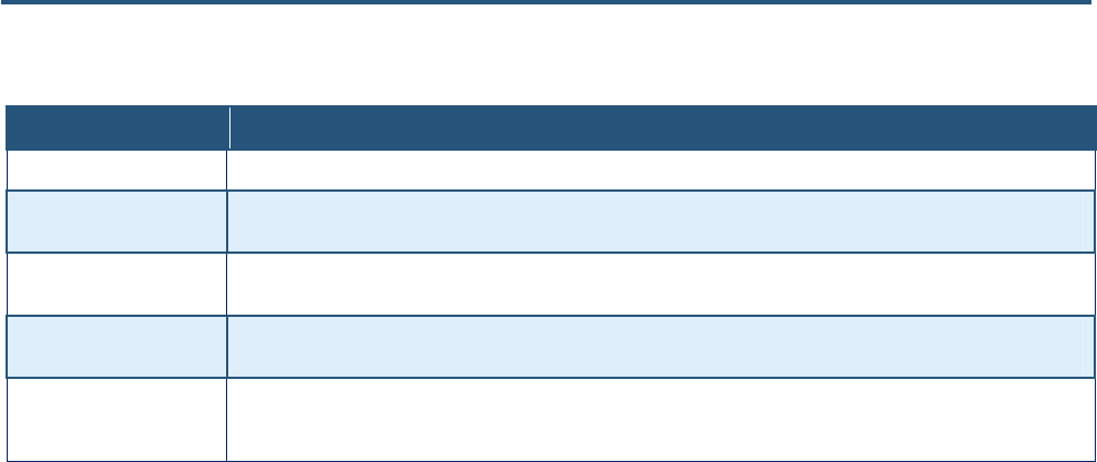
Table 6. Local IP Configuration Page Options
Option Description
Gateway Address Enter the Gateway’s IP address using the format 00.00.00.00.
Subnet Mask Enter the subnet mask using the format 00.00.00.00. You can select an appropriate subnet mask based on the number of
devices that will connect to your network.
DHCP Beginning Address Enter the starting IP address in the range of IP addresses that the DHCP server will allocate. Because the Gateway’s
default IP address is 192.168.0.1, the Beginning Address must be 192.168.0.2 or greater.
DHCP Ending Address Enter the ending IP address in the range of IP addresses that the DHCP server will allocate. Because the Gateway’s
default IP address is 192.168.0.1, the Ending Address must not exceed 192.168.0.251.
DHCP Lease Time Enter the amount of time that a network device is allowed connection to the Gateway using its current dynamic IP address.
Use the drop-down box to select Minutes, Hours, Days, Weeks, or Forever. When this lease time expires, the device is
assigned a new dynamic IP address automatically.
33
SMCD3GNV4 and SMCD3GNV4E Wireless EMTA Gateway Administrator Manual
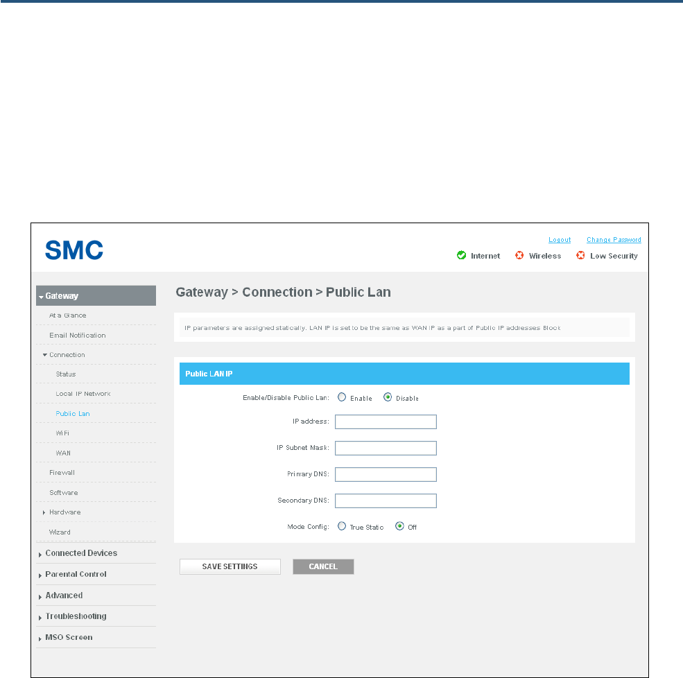
Public LAN Page
Path: Gateway > Connection > Public Lan
The Public Lan page lets you configure static IP address information for the Gateway and enable the
Gateway to use static IP addressing.
Figure 19. Public Lan Page
34
SMCD3GNV4 and SMCD3GNV4E Wireless EMTA Gateway Administrator Manual
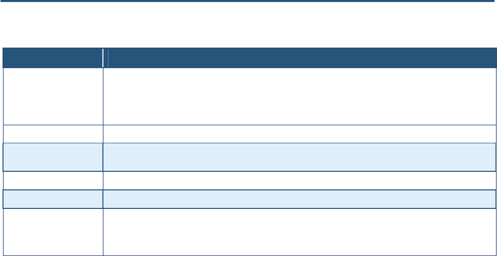
Table 7. Public Lan Configuration Options
Option Description
Enable/Disable Public Lan Enables or disables the static IP address settings specified on this page.
• Enable = the Gateway uses the static IP address settings defined on this page. If you click Enable, complete the
remaining fields on the page.
• Disable = the Gateway does not use the static IP address settings defined on this page.
IP Address When Enable/Disable Public LAN is enabled, enter the Gateway’s IP address using the format 00.00.00.00.
IP Subnet Mask When Enable/Disable Public LAN is enabled, enter the subnet mask using the format 00.00.00.00. You can select an
appropriate subnet mask based on the number of devices that will connect to your network.
Primary DNS When Enable/Disable Public LAN is enabled, enter the primary domain name system IP address from your ISP.
Secondary DNS When Enable/Disable Public LAN is enabled, enter the secondary domain name system IP address from your ISP.
Mode Config Enables or disables static IP addressing for the Gateway.
• True Static = configures the Gateway to use the static IP address settings configured on this page.
• Off = the Gateway does not use a static IP address.
35
SMCD3GNV4 and SMCD3GNV4E Wireless EMTA Gateway Administrator Manual
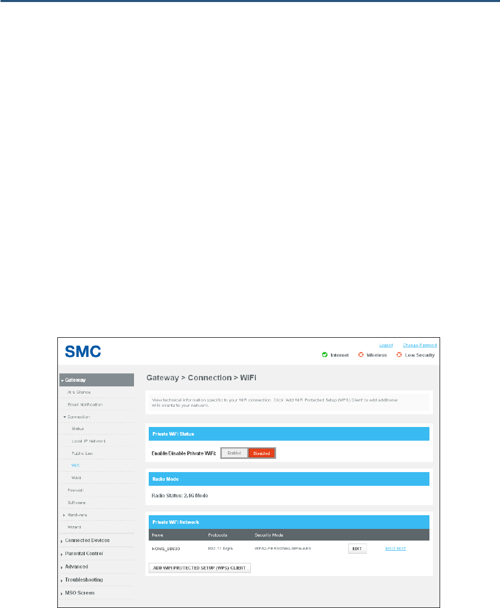
WiFi Page
Path: Gateway > Connection > WiFi
The WiFi page shows advanced information about the Gateway’s Wi-Fi connections.
The Wi-Fi information on this page is organized into three areas
y Private WiFi Status provides a button for enabling or disabling the Gateway’s Wi-Fi status.
y Radio Mode is a read-only field that shows the frequency of the Gateway’s wireless radio.
y Private WiFi Network shows the name of the Wi-Fi network to which the Gateway is connected,
along with the protocol and security mode. An EDIT button lets you change settings for the network
(see page 36). An mso edit button lets you change the Gateway’s private Wi-Fi network
configuration (see page 38).
An ADD WIFI PROTECTED SETUP (WPS) CLIENT button at the bottom of the page displays the WPS
page for adding wireless clients (see page 41).
Figure 20. WiFi Page
36
SMCD3GNV4 and SMCD3GNV4E Wireless EMTA Gateway Administrator Manual
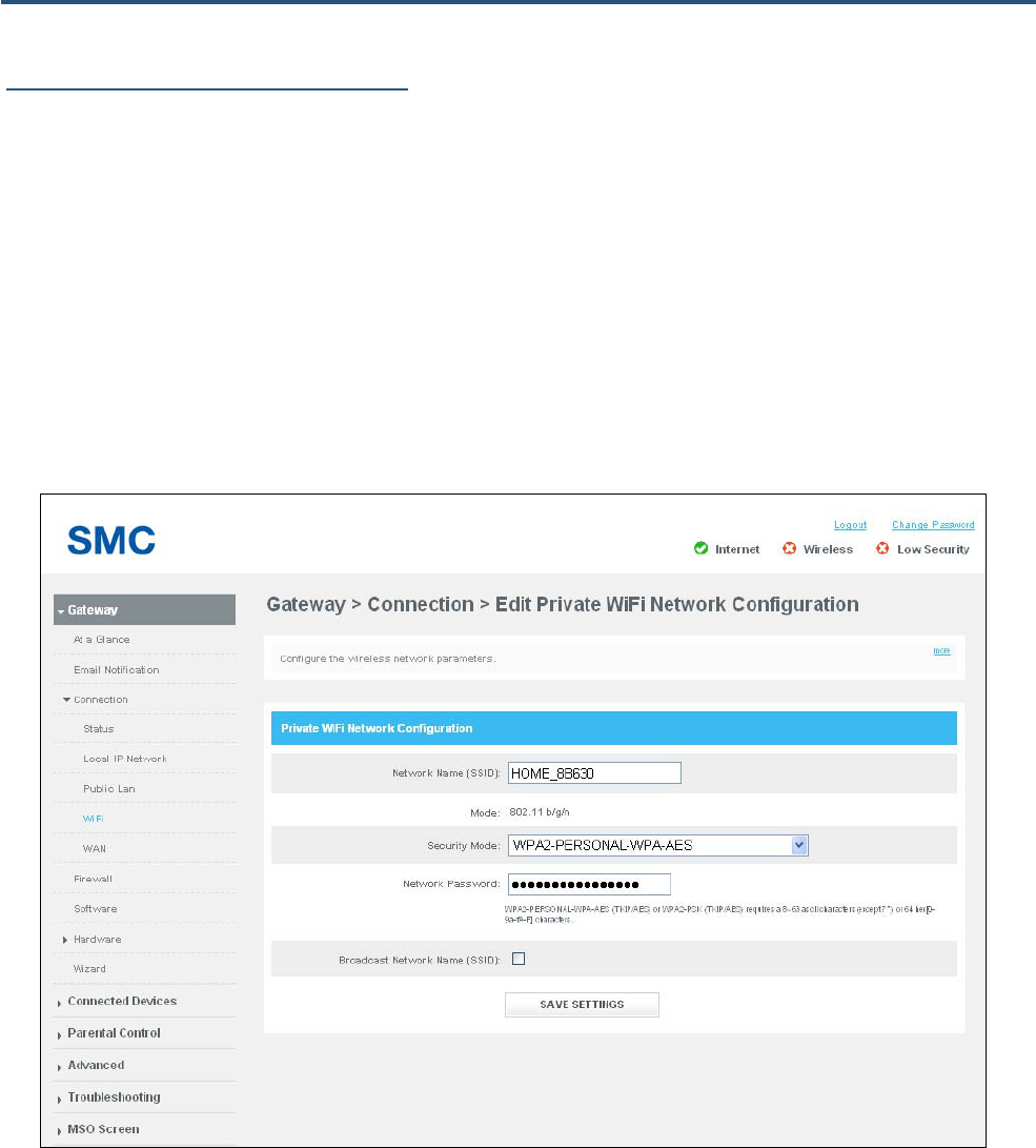
Editing Private WiFi Network Settings
The row below Private WiFi Network on the WiFi page shows the name (SSID), protocol, and security
mode of the Gateway’s Wi-Fi network connection. Using the EDIT button on the right side of the row,
you can change these settings.
To edit the Gateway’s private WiFi network settings:
1. Under Private WiFi Network on the WiFI page, click the EDIT button. A page similar to the one in
Figure 21 appears.
2. Complete the options in the page (see Table 8).
3. Click SAVE SETTINGS.
Figure 21. Edit Private WiFi Network Configuration Page
37
SMCD3GNV4 and SMCD3GNV4E Wireless EMTA Gateway Administrator Manual
Table 8. Edit Private WiFi Network Configuration Page Options
Option Description
Network Name (SSID) Enter a name for the wireless network. The Wi-Fi name will make it more obvious for other devices to know which network
they are connecting to.
Mode A read-only field that shows the current mode for this network (for example, 802.11 b/g/n).
Security Mode To prevent other computers in the area from using your Internet connection, secure your wireless network by selecting an
encryption method from this drop-down list. There are several selections available, including the following. (Risky
appears next to selections that provide little or no protection).
• Open = wireless transmissions are not protected.
• WEP = basic encryption and therefore least secure (i.e., it can be easily cracked, but is compatible with a wide range
of devices including older hardware). WEP 64- and 128-bit selections are provided.
• WPA-PSK = designed for home and small-office networks. Each wireless network device encrypts the network traffic
using a 256-bit key. Select this option if your wireless adapters support Wi-Fi Protected Access Pre-shared Key
(WPA-PSK) mode.
• WPA2 = second generation of WPA that adds CCMP encryption with mathematically proven security. Select this
option if your wireless adapters support WPA2.
Network Password If you select one of the WEP or WPA encryption settings, enter the case-sensitive password used for encryption and
decryption. For security, each typed password character is masked as a dot (λ). If you specify a hexadecimal password,
use the letters A to F and numbers 0 to 9.
• WEP 64 requires a 5 ASCII character or 10 hexadecimal character password.
• WEP 128: requires a 13 ASCII character or 16 hexadecimal character password.
• WPA-PSK (TKIP) requires an 8-to-63 ASCII character or a 64 hexadecimal character password.
• WPA-PSK (AES) requires an 8-to-63 ASCII character or a 64 hexadecimal character password.
• WPA2-PSK (TKIP) requires an 8-to-63 ASCII character password.
Broadcast Network Name
(SSID) Check to enable broadcasting the SSID. When wireless devices survey wireless networks to associate with, they will
detect the SSID broadcast by the Gateway.
38
SMCD3GNV4 and SMCD3GNV4E Wireless EMTA Gateway Administrator Manual
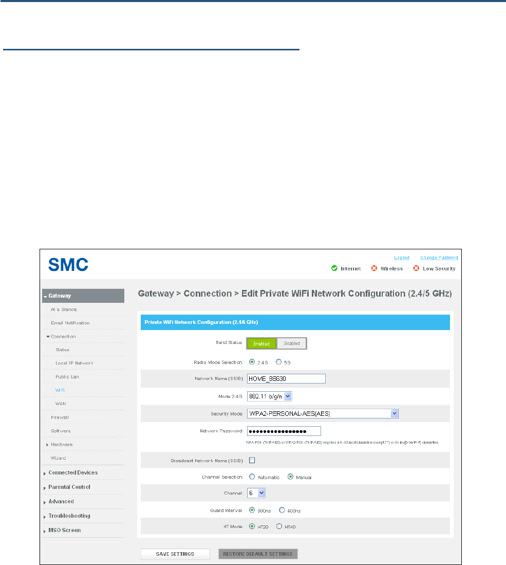
Configuring Private WiFi Network Configuration Settings
The row below Private WiFi Network on the WiFi page shows the name (SSID), protocol, and security
mode of the Gateway’s Wi-Fi network connection. Using the MSO EDIT link on the right side of the row,
you can change the Gateway’s private WiFI network configuration settings..
To edit the Gateway’s private WiFi network configuration settings:
1. Under Private WiFi Network on the WiFI page, click the MSO EDIT button. A page similar to the
one in Figure 22 appears.
2. Complete the options in the page (see Table 9).
3. Click SAVE SETTINGS.
Figure 22. Edit Private WiFi Network Configuration 2.4/5 GHz Page

39
SMCD3GNV4 and SMCD3GNV4E Wireless EMTA Gateway Administrator Manual
Table 9. Edit Private WiFi Network Configuration 2.4/5 GHz Page Options
Option Description
Band Status Lets you enable or disable the Gateway’s 2.4/5 GHz band operation.
Radio Mode Selection Click the Gateway wireless radio to be used. Choices are:
• 2.4G = 2.4 GHz radio is used.
• 5G = 5 GHz radio is used.
Network Name (SSID) Enter a name for the private Wi-Fi network. The network name will make it more obvious for other devices to know which
network they are connecting to.
Mode 2.4G If Radio Mode Selection is set to 2.4G, use this field to select the Gateway wireless mode. Choices are:
• 802.11 b = select this setting if your wireless network consists of IEEE 802.11b devices only.
• 802.11 g = select this setting if your wireless network consists of IEEE 802.11g devices only.
• 802.11 n = select this setting if your wireless network consists of IEEE 802.11n devices only.
• 802.11 b/g = select this setting if your wireless network consists of IEEE 802.11b and 802.11g devices.
• 802.11 g/n = select this setting if your wireless network consists of IEEE 802.11g and 802.11n devices.
• 802.11 b/g/n = select this setting if your wireless network consists of IEEE 802.11b, 802.11g, and 802.11n devices.
Mode 5G If Radio Mode Selection is set to 5G, use this field to select the Gateway wireless mode. Choices are:
• 802.11 a = select this setting if your wireless network consists of IEEE 802.11a devices only.
• 802.11 a/n = select this setting if your wireless network consists of IEEE 802.11a and 802.11n devices.
Security Mode To prevent other computers in the area from using your Internet connection, secure your wireless network by selecting an
encryption method from this drop-down list. There are several selections available, including the following. (Risky
appears next to selections that provide little or no protection).
• Open = wireless transmissions are not protected.
• WEP = basic encryption and therefore least secure (i.e., it can be easily cracked, but is compatible with a wide range
of devices including older hardware). WEP 64- and 128-bit selections are provided.
• WPA-PSK = designed for home and small-office networks. Each wireless network device encrypts the network traffic
using a 256-bit key. Select this option if your wireless adapters support Wi-Fi Protected Access Pre-shared Key
(WPA-PSK) mode.
• WPA2 = second generation of WPA that adds CCMP encryption with mathematically proven security. Select this
option if your wireless adapters support WPA2.
Network Password If you select one of the WEP or WPA encryption settings, enter the case-sensitive password used for encryption and
decryption. For security, each typed password character is masked as a dot (λ). If you specify a hexadecimal password,
use the letters A to F and numbers 0 to 9.
• WEP 64 requires a 5 ASCII character or 10 hexadecimal character password.
• WEP 128: requires a 13 ASCII character or 16 hexadecimal character password.
• WPA-PSK (TKIP) requires an 8-to-63 ASCII character or a 64 hexadecimal character password.
• WPA-PSK (AES) requires an 8-to-63 ASCII character or a 64 hexadecimal character password.
• WPA2-PSK (TKIP) requires an 8-to-63 ASCII character password.
Broadcast Network Name
(SSID) Check to enable broadcasting of the SSID. When wireless devices survey wireless networks to associate with, they will
detect the SSID broadcast by the Gateway.
Channel Selection Select how the Gateway will select a channel for communicating over the wireless network. Choices are:
• Automatic = the Gateway selects the channel automatically.
• Manual = the Gateway uses the channel specified in the Channel option.
40
SMCD3GNV4 and SMCD3GNV4E Wireless EMTA Gateway Administrator Manual
Option Description
Channel If Channel Selection is set to Manual, specify the appropriate channel from the list provided to correspond with your
network settings. Choices are 1, 6, and 11. The default setting is 6, which refers to radio frequency ranges within the 2.4
GHz range. You can change this setting if necessary; however, all devices in your wireless network must use the same
channel to work properly.
Guard Interval Select a guard interval. The guard interval is the period of time, in nanoseconds, that the Gateway listens between
packets. Choices are:
• 800 ns = long guard interval.
• 400 ns = short guard interval.
HT Mode Select the appropriate high-throughput (HT) mode. Choices are:
• HT20
• HT40
41
SMCD3GNV4 and SMCD3GNV4E Wireless EMTA Gateway Administrator Manual
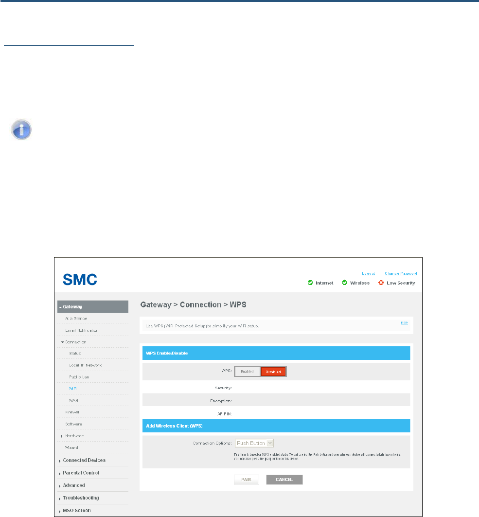
Configuring WPS Settings
Using the WiFi page (described on page 33) or the Computers page (described on page 56), you can
enable or disable the Gateway’s WPS operation and configure the connection options for WPS push
button or pin number operation.
Note: You must enable WPS before a wireless device can connect to the Gateway using WPS.
To configure WPS settings:
1. From the WiFi or Computers page, click the ADD WIFI PROTECTED SETUP (WPS) CLIENT button.
The WPS page appears (see Figure 22).
2. Complete the options in the WPS page (see Table 9).
Figure 23. WPS Page
42
SMCD3GNV4 and SMCD3GNV4E Wireless EMTA Gateway Administrator Manual
Table 10. WPS Page Options
Option Description
WPS Lets you enable or disable WPS. If you click Enabled, complete the remaining fields on the page.
Security A read-only field that shows the Gateway’s security settings.
Encryption A read-only field that shows the Gateway’s encryption settings.
AP PIN A read-only field that shows the Access Point’s personal identification number.
Connection Options Select the method used to make the WPS connection between wireless devices and the Gateway. Choices are:
• Push Button = select this option to use the WPS button on the top panel of the Gateway and the wireless device to
make the connection.
• Pin Number = select this option to enter an 8-digit PIN to configure WPS. If you select this option, you must enter the
same 8-digit PIN in both the Gateway and the wireless client to make the connection.
PAIR button Click this button and push the WPS button on the wireless client to create the connection. The connection is made within
two minutes. You can also press the WPS button on the front panel of this Gateway to initiate WPS instead of clicking the
PAIR button.
43
SMCD3GNV4 and SMCD3GNV4E Wireless EMTA Gateway Administrator Manual
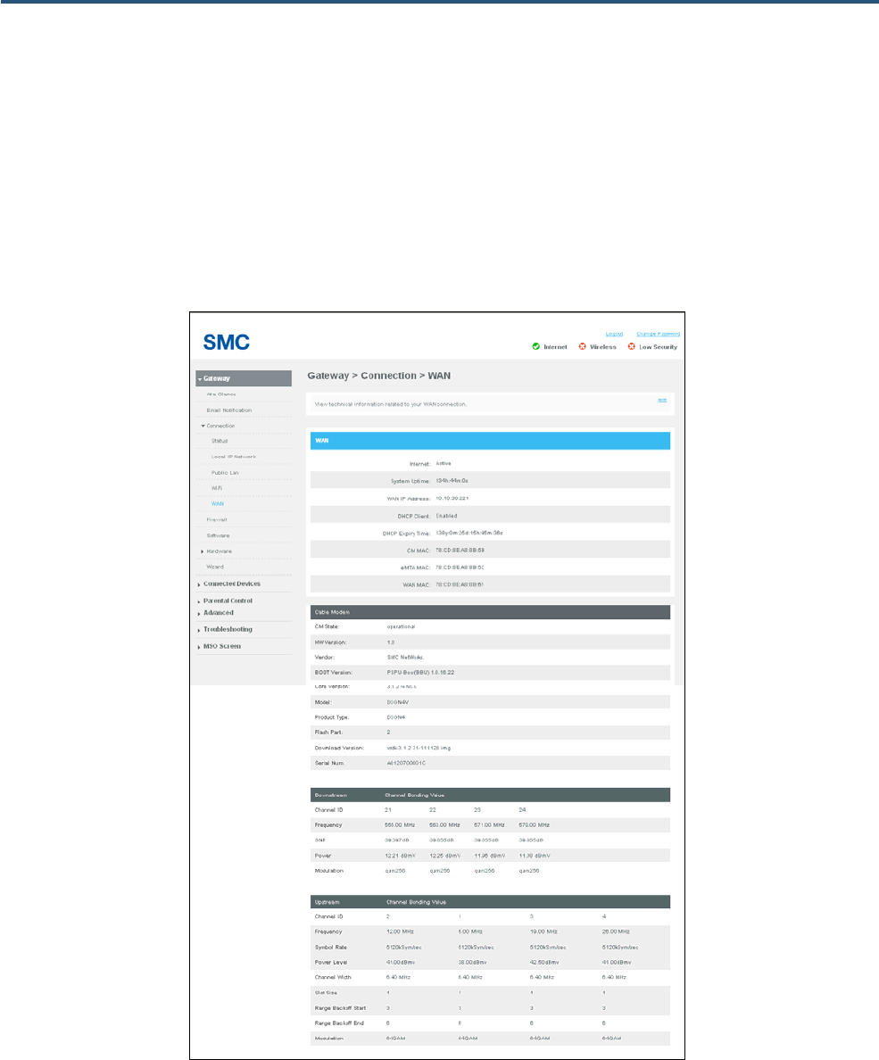
WAN Page
Path: Connection > WAN or click the VIEW button in the WAN IP Network area of the Status page
The WAN Network page is a read-only page that shows information about the Wide Area Network,
cable modem, and downstream and upstream bonding values. This information is useful when
contacting Customer Center or troubleshooting technical problems.
Figure 24. WAN Page
44
SMCD3GNV4 and SMCD3GNV4E Wireless EMTA Gateway Administrator Manual
Table 11. WAN Page Options
Option Description
WAN
Internet A read-only field that shows the Internet connection status.
System Uptime A read-only field that shows the system uptime counting from its bootup.
WAN IP Address A read-only field that shows t he WAN IP address obtained from the service provider.
DHCP Client A read-only field that shows the DHCP Client function is enable or disable.
DHCP Expiry Time A read-only field that shows the expired time currently left of DHCP client. Once the time expires, the configuration
might stop working.
CM MAC A read-only field that shows the MAC address of the CM.
eMTA MAC A read-only field that shows the MAC address of the eMTA.
WAN MAC A read-only field that shows the MAC address of the WAN interface.
Cable Modem
Read-only fields show technical information related to your cable modem, such as the hardware version, vendor, and boot and core versions.
Downstream
Downstream channel bonding lets the Gateway receive downstream traffic on multiple downstream channels. These read-only fields show the
downstream channel bonding values.
Upstream
Upstream channel bonding is a way to increase upstream bandwidth by transmitting data on multiple upstream channels simultaneously. These read-only
fields show the upstream channel bonding values.
45
SMCD3GNV4 and SMCD3GNV4E Wireless EMTA Gateway Administrator Manual
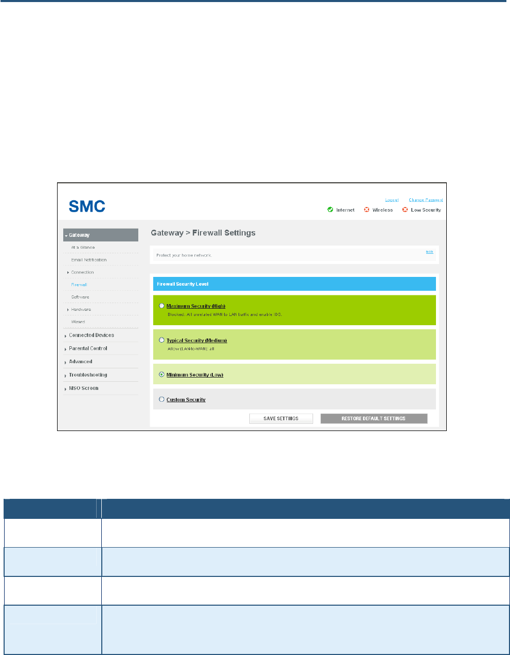
Firewall Settings Page
Path: Gateway > Firewall
The Gateway includes a built-in firewall whose security level can be selected using the Firewall Settings
page. Security levels range from minimum (low security) to maximum (high security). A Custom
Security option lets you customize security settings to suit your requirements.
Figure 25. Firewall Settings Page
Table 12. Firewall Settings Page Options
Option Description
Maximum Security (High) Maximum security is the highest level of firewall security. It blocks all applications including voice applications (such as
Gtalk and Skype) and P2P applications, but permits Internet browsing, email, VPN, DNS, and iTunes services.
Typical Security (Medium) Typical security is the medium level of firewall security. It blocks P2P applications and pings to the Gateway, while
permitting all other traffic.
Minimum Security (Low) Minimum security is the lowest level of firewall security. It does not block applications and traffic. Select this low level
security if you are not familiar with firewall settings.
Custom Security This security level is pre-configured to block all local network access from the Internet, except “trusted computers" defined
on the Managed Sites page (see page 59) and Managed Services page (see page 64). Only commonly used services, such
as Web browsing and E-mail, are permitted. If you select this option, a list of check boxes let you disable the entire firewall
or block certain traffic (see Figure 26).
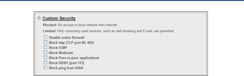
46
SMCD3GNV4 and SMCD3GNV4E Wireless EMTA Gateway Administrator Manual
Figure 26. Custom Firewall Security Settings
47
SMCD3GNV4 and SMCD3GNV4E Wireless EMTA Gateway Administrator Manual
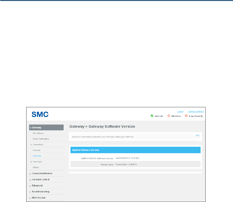
Gateway Software Version Page
Path: Gateway > Software
The Gateway Software Version page is a read-only page that shows information about the system
software version information about the Gateway.
The system software information shown includes:
y eMTA and DOCSIS software version
y Packet cable
Figure 27. Gateway Software Version Page
48
SMCD3GNV4 and SMCD3GNV4E Wireless EMTA Gateway Administrator Manual
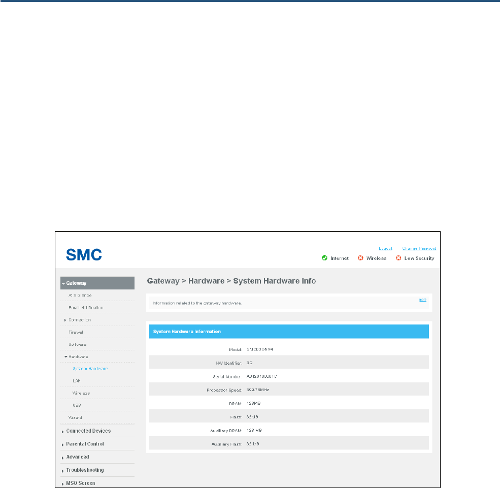
System Hardware Info Page
Path: Gateway > Hardware > System Hardware
The System Hardware Info page is a read-only page that shows the following information about the
Gateway hardware:
y Model, hardware identifier, and serial number
y Processor speed
y Dynamic Random Access Memory (DRAM), flash, auxiliary DRAM, and auxiliary flash
Figure 28. System Hardware Info Page
49
SMCD3GNV4 and SMCD3GNV4E Wireless EMTA Gateway Administrator Manual
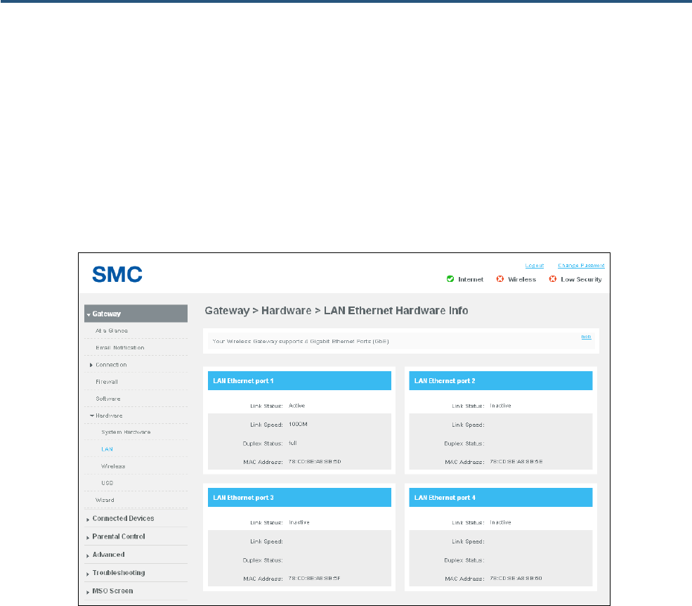
LAN Ethernet Hardware Info Page
Path: Gateway > Hardware > LAN
The LAN Ethernet Hardware Info page is a read-only page that shows the link status and MAC address
of the Gateway’s four Gigabit Ethernet LAN ports. If a device is connected to a Gigabit Ethernet port,
the Link Status is Active; otherwise, the Link Status is Inactive.
Figure 29. LAN Ethernet Hardware Info Page
50
SMCD3GNV4 and SMCD3GNV4E Wireless EMTA Gateway Administrator Manual
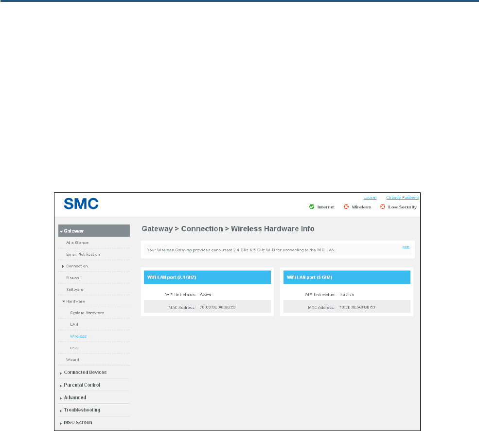
Wireless Hardware Info Page
Path: Gateway > Hardware > Wireless
The Wireless Hardware Info page is a read-only page that shows the connection status and MAC
address of the wireless network.
The Gateway supports concurrent 2.4 GHz and 5 GHz Wi-Fi wireless connections. If a wireless client is
connected to the Gateway, the WiFi link status is Active; otherwise, it is Inactive.
Figure 30. Wireless Hardware Info Page
51
SMCD3GNV4 and SMCD3GNV4E Wireless EMTA Gateway Administrator Manual
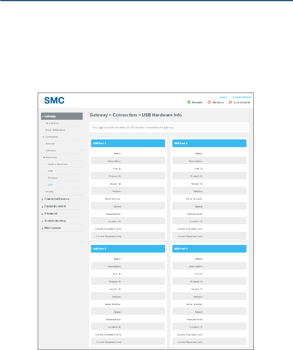
USB Hardware Info Page
Path: Gateway > Hardware > USB
The USB Hardware Info page is a read-only page that shows the status and information about USB
devices connected to the Gateway.
Figure 31. USB Hardware Info Page

52
SMCD3GNV4 and SMCD3GNV4E Wireless EMTA Gateway Administrator Manual
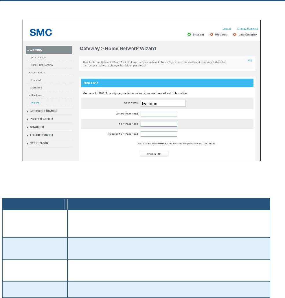
Home Network Wizard Page
Path: Gateway > Wizard
The Home Network Wizard is a 2-page wizard for configuring your home network. If you are a new or
novice user, we recommend you use wizard to configure the Gateway’s basic settings. The wizard
appears automatically when you log in to the Web management interface.
Figure 32 shows the first page of the wizard and Table 13 describes the options. When you complete
the options on the first page, click NEXT STEP to display the second page of the wizard (see Figure 33
and Table 14).
53
SMCD3GNV4 and SMCD3GNV4E Wireless EMTA Gateway Administrator Manual
Figure 32. Example of Home Network Wizard – Page 1
Table 13. Home Network Wizard – Page 1 Options
Option Description
Gateway Name Enter a name you want to assign to the Gateway. Assign a name so that this device will not be confused with
other devices on your wireless network. We recommend you use a name that is meaningful to you so you
can identify the Gateway easily. The Gateway name is case sensitive and can contain from 8 to 20
alphanumeric characters, but no spaces or special characters.
Current Password Enter the current case-sensitive password. For security purposes, every typed character appears as a dot
(y). The default password is not shown for security purposes. The password is case sensitive and can
contain from 8 to 32 characters, but no spaces or special characters.
New Password Enter the new case-sensitive password you want to use to protect your network. The password can contain
from 8 to 32 alphanumeric characters, but no spaces or special characters. Spaces count as password
characters. For security purposes, every typed character appears as a dot (y).
Re-enter New Password Enter the same case-sensitive password you typed in the New Password field. For security purposes, every
typed character is masked as a dot (y).
54
SMCD3GNV4 and SMCD3GNV4E Wireless EMTA Gateway Administrator Manual
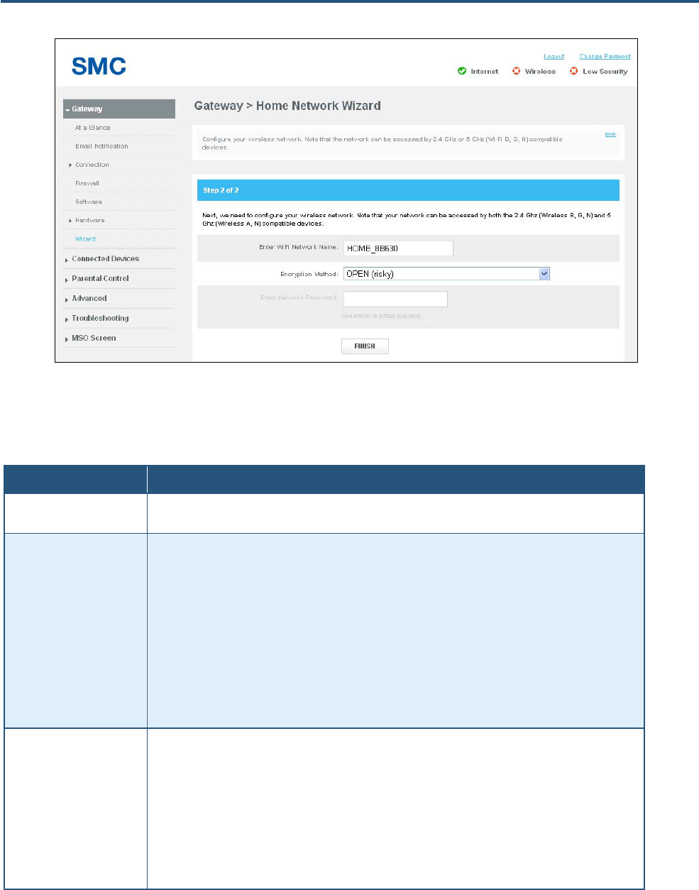
Figure 33. Example of Home Network Wizard - Page 2
Table 14. Home Network Wizard – Page 2 Options
Option Description
Enter WiFi Network Name Enter a name for your wireless network (typically, the SSID). The Wi-Fi name will make it more obvious for
other devices to know which network they are connecting to.
Encryption Method To prevent other computers in the area from using your Internet connection, secure your wireless network by
selecting an encryption method from this drop-down list. There are several selections available, including the
following. (Risky appears next to selections that provide little or no protection).
• Open = wireless transmissions are not protected.
• WEP = basic encryption and therefore least secure (i.e., it can be easily cracked, but is compatible with a
wide range of devices including older hardware). WEP 64- and 128-bit selections are provided.
• WPA-PSK = designed for home and small-office networks. Each wireless network device encrypts the
network traffic using a 256-bit key. Select this option if your wireless adapters support Wi-Fi Protected
Access Pre-shared Key (WPA-PSK) mode.
• WPA2 = second generation of WPA that adds CCMP encryption with mathematically proven security.
Select this option if your wireless adapters support WPA2.
Enter Network Password If you select one of the WEP or WPA encryption settings, enter the case-sensitive password used for
encryption and decryption. For security, each typed password character is masked as a dot (λ). If you
specify a hexadecimal password, use the letters A to F and numbers 0 to 9.
• WEP 64 requires a 5 ASCII character or 10 hexadecimal character password.
• WEP 128: requires a 13 ASCII character or 16 hexadecimal character password.
• WPA-PSK (TKIP) requires an 8-to-63 ASCII character or a 64 hexadecimal character password.
• WPA-PSK (AES) requires an 8-to-63 ASCII character or a 64 hexadecimal character password.
• WPA2-PSK (TKIP) requires an 8-to-63 ASCII character password.

55
SMCD3GNV4 and SMCD3GNV4E Wireless EMTA Gateway Administrator Manual
Connected Devices Page
The Connected Devices page lets you:
y View and edit computers connected to the Gateway’s LAN – see page 56.
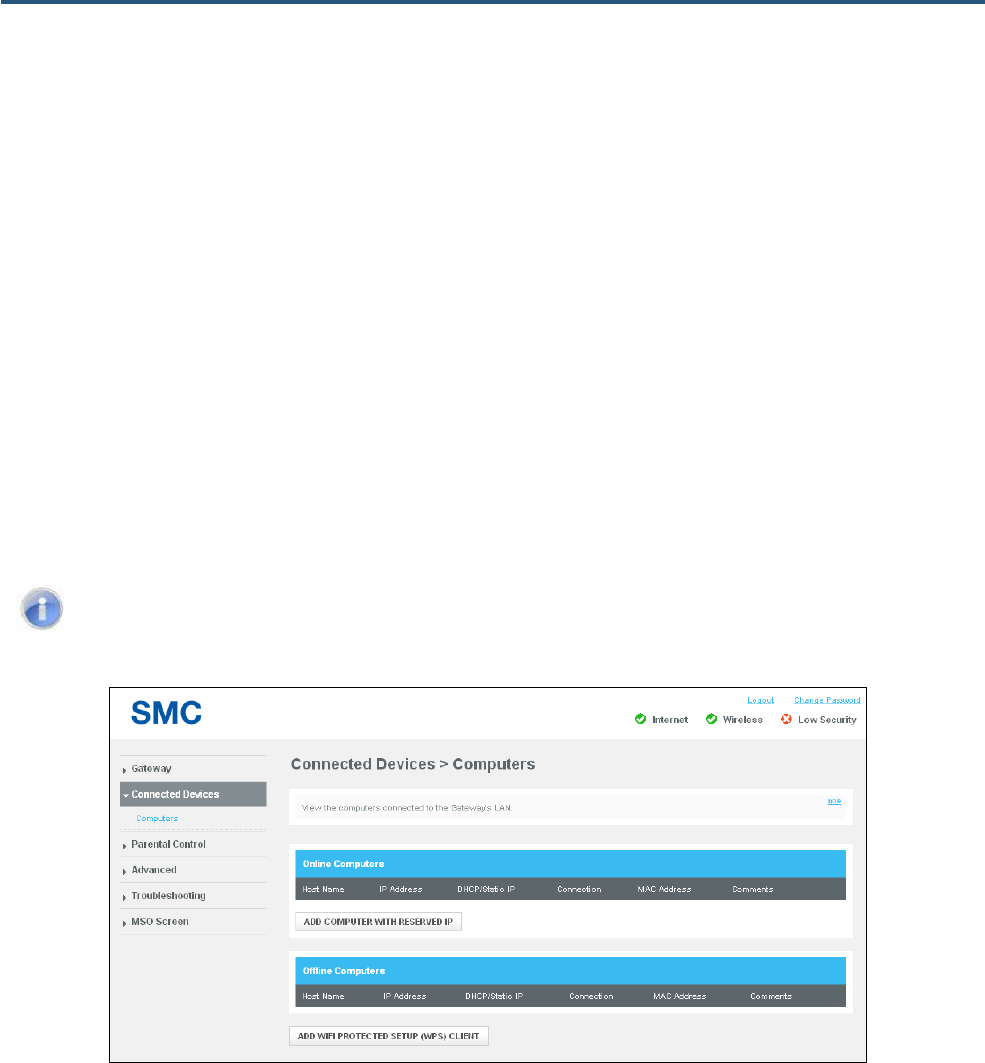
56
SMCD3GNV4 and SMCD3GNV4E Wireless EMTA Gateway Administrator Manual
Computers Page
Path: Connected Devices > Computers
The Gateway automatically discovers computers attached to it. The Computers page contains two
areas:
y Online Computers shows information about computers that are currently online. The ADD
COMPUTER WITH RESERVED IP button lets you add computers (see page 57). After you add a
computer, an Edit button next to the computer lets you change the computer’s settings.
y Offline Computers shows information about computers that are currently offline.
At the bottom of the page, the ADD WIFI PROTECTED SETUP (WPS) CLIENT button lets you enable
or disable WPS and configure WPS settings for your wireless networks. For more information, see
“Configuring Private WiFi Network Configuration Settings” on page 38.
Note: You must enable WPS before a wireless device can connect to the Gateway using WPS.
Figure 34. Computers Page
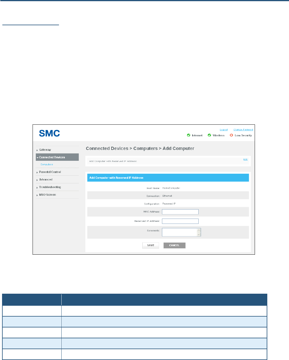
57
SMCD3GNV4 and SMCD3GNV4E Wireless EMTA Gateway Administrator Manual
Adding Computers
Using the ADD COMPUTER WITH RESERVED IP button, you can add computers with reserved IIP
addresses.
1. On the Computers page, click the ADD COMPUTER WITH RESERVED IP button. The Add
Computer page appears (see Figure 35).
2. Complete the options in the Add Computer page (see Table 15).
3. Click SAVE. The computer appears under Online Computers on the Computers page. An Edit
button next to the computer you added lets you change the settings.
Figure 35. Add Computer Page
Table 15. Add Computer Page Options
Option Description
Host Name A read-only field that shows the computer’s host name.
Connection A read-only field that shows the connection method (for example, Ethernet).
MAC Address Enter the Media Access Control (MAC) address of the computer you want to connect.
Reserved IP Add5ess Enter the IP address of the connected computer.
Comments Add any optional comments about the device, such as an identifying description about the computer.

58
SMCD3GNV4 and SMCD3GNV4E Wireless EMTA Gateway Administrator Manual
Parental Control Page
Regulating Web browsing can prevent children and workers from accessing dangerous content on the
Internet, or having to make judgment calls over suitable relationships in chat-rooms. The fact is, Web
sites, chat-room users, and downloaded programs may not have the best interests of you, your family,
or your workers at heart. The unscrupulous may try to manipulate the people you care about or try to
gain trust, which may result in unacceptable access to your family, your coworkers, your computer, or
personal information.
The Parental Control page lets you regulate Internet access by lets you:
y Restrict access to certain Web sites and keywords, and define trusted computers that can access
those Web sites and keywords – see page 59.
y Prevent access to certain applications and services, and define trusted computers that can access
those applications and services – see page 64.
y Configure device list that are allowed/blocked to connect to the network – see page 67.
y Generate, print, and download reports – see page 71.
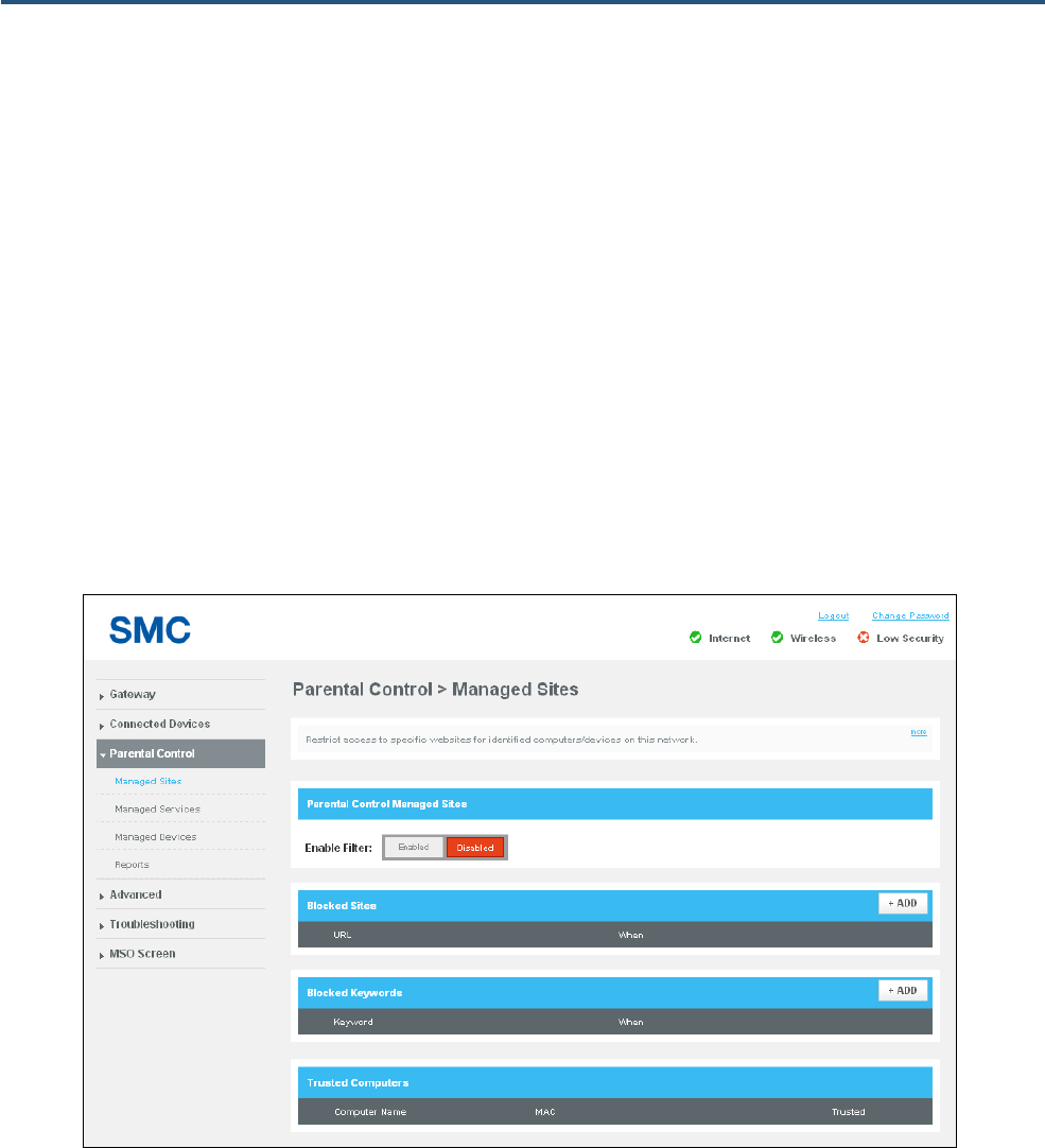
59
SMCD3GNV4 and SMCD3GNV4E Wireless EMTA Gateway Administrator Manual
Managed Sites Page
Path: Parental Control > Managed Sites
The Managed Sites page lets you configure:
y Blocked sites – see page 60.
y Blocked keywords – see page 62.
y Trusted computers that can access the blocked sites and keywords – see page 63.d
After configuring filters on this page, use the Enable Filter buttons to enable or disable the filters:
y Click Enabled to enable the parental control filters configured on this page.
y Click Disabled to disable the parental control filters configured on this page.
Figure 36. Managed Sites Page
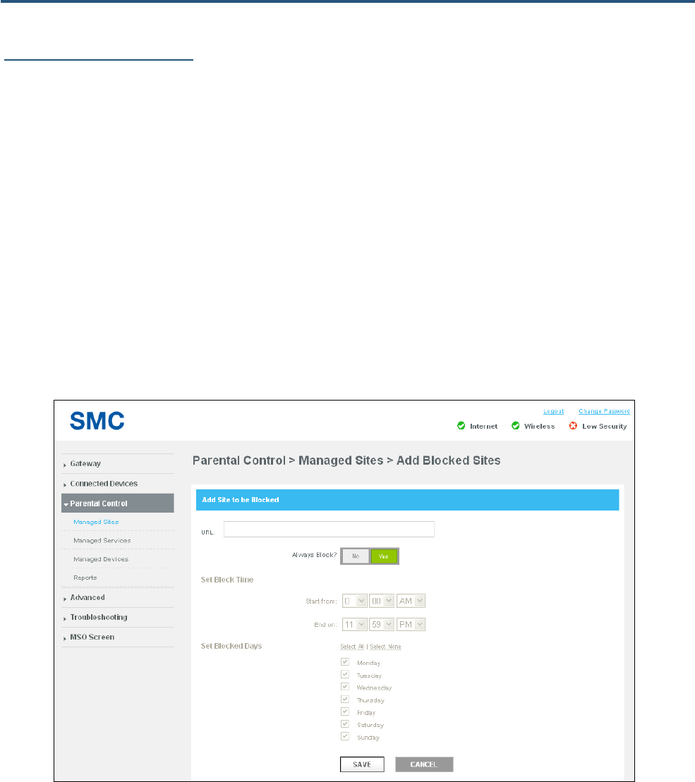
60
SMCD3GNV4 and SMCD3GNV4E Wireless EMTA Gateway Administrator Manual
Configuring Blocked Sites
Using the Managed Sites page, you can block access to certain Web sites from local computers.
To define blocked sites:
1. In the Blocked Sites area on the Managed Sites page, click the +ADD button. The Add Blocked
Sites page appears (see Figure 37).
2. Complete the fields in the Add Blocked Site page (see Table 16).
3. Click SAVE. The blocked site appears in the Blocked Sites table in the Managed Sites page.
4. To edit a blocked site, click the EDIT button next to the blocked site you want to modify, edit the
settings (see Table 16), and click SAVE.
5. To delete a blocked site, click the X next to the site. When a precautionary message appears, click
OK to delete the blocked site or CANCEL to retain it.
Figure 37. Add Blocked Sites Page
61
SMCD3GNV4 and SMCD3GNV4E Wireless EMTA Gateway Administrator Manual
Table 16. Add Blocked Sites Page Options
Option Description
URL Enter the URL you want blocked.
Always Block? Select whether you want the Gateway to always block this URL. Choices are
• No = the Gateway does not always block this URL. Use Set Block Time and Set Blocked Days to instruct
the Gateway when to block this URL.
• Yes = the Gateway always blocks this URL until you remove the block.
Set Block Time
Start from If you selected No for Always Block?, select the time when the Gateway is to start blocking this URL.
End on If you selected No for Always Block?, select the time when the Gateway is to stop blocking this URL.
Set Blocked Days
Select All Click this link to select all seven days. This link is not available if you selected Yes for Always Block?
Select None Click this link to deselect all seven days. This link is not available if you selected Yes for Always Block?
Monday – Sunday Check the check boxes that correspond to the days when you want the Gateway to block this URL. These
checkboxes are not available if you selected Yes for Always Block?
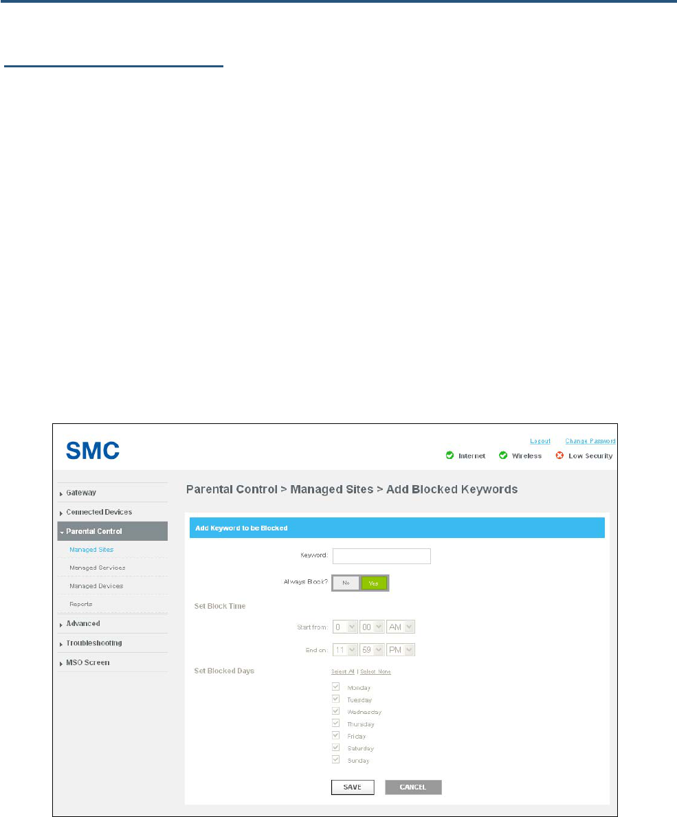
62
SMCD3GNV4 and SMCD3GNV4E Wireless EMTA Gateway Administrator Manual
Configuring Blocked Keywords
Using the Managed Sites page, you can block access to certain key words from local computers.
To define blocked keywords:
1. In the Blocked Keywords area on the Managed Sites page, click the +ADD button. The Add
Blocked Keywords page appears (see Figure 38).
2. Complete the fields in the Add Blocked Keywords page (see Table 17).
3. Click SAVE. The blocked keyword appears in the Blocked Keywords table in the Managed Sites
page.
4. To edit a blocked keyword, click the EDIT button next to the blocked keyword you want to modify,
edit the settings (see Table 17), and click SAVE.
5. To delete a blocked keyword, click the X next to the keyword. When a precautionary message
appears, click OK to delete the blocked keyword or CANCEL to retain it.
Figure 38. Add Blocked Keywords Page
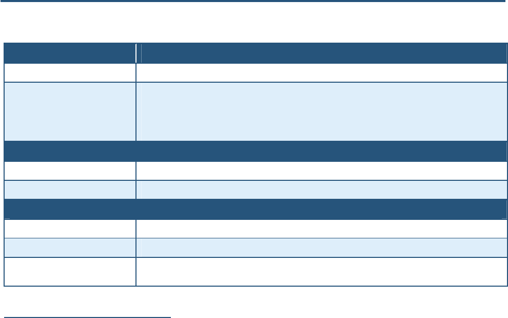
63
SMCD3GNV4 and SMCD3GNV4E Wireless EMTA Gateway Administrator Manual
Table 17. Add Blocked Keywords Page Options
Option Description
Keyword Enter the keyword you want blocked.
Always Block? Select whether you want the Gateway to always block this keyword. Choices are
• No = the Gateway does not always block this keyword. Use Set Block Time and Set Blocked Days to
instruct the Gateway when to block this keyword.
• Yes = the Gateway always blocks this keyword until you remove the block.
Set Block Time
Start from If you selected No for Always Block?, select the time when the Gateway is to start blocking this keyword.
End on If you selected No for Always Block?, select the time when the Gateway is to stop blocking this keyword.
Set Blocked Days
Select All Click this link to select all seven days. This link is not available if you selected Yes for Always Block?
Select None Click this link to deselect all seven days. This link is not available if you selected Yes for Always Block?
Monday – Sunday Check the check boxes that correspond to the days when you want the Gateway to block this keyword. These
checkboxes are not available if you selected Yes for Always Block?
Configuring Trusted Computers
Using the Managed Sites page, you can define trusted computers that are allowed to access the
blocked Web sites and keywords.
To define trusted computers, in the Trusted Computers area on the Managed Sites page:
y Click Yes to designate a computer as trusted.
OR
y Click No to designate the computer as not trusted.
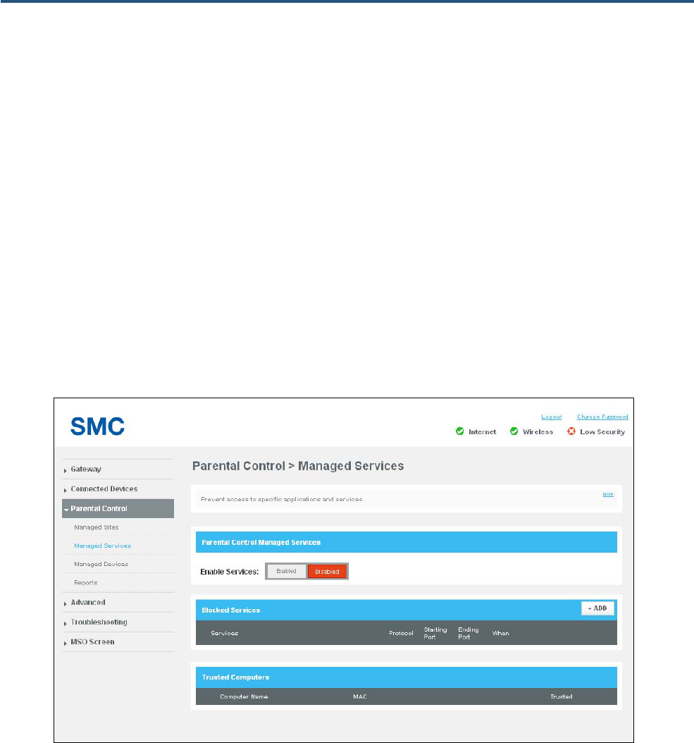
64
SMCD3GNV4 and SMCD3GNV4E Wireless EMTA Gateway Administrator Manual
Managed Services Page
Path: Parental Control > Managed Services
The Managed Services page lets you configure:
y Blocked applications and services – see page 65.
y Trusted computers that can access the blocked applications and services – see page 66.
After configuring services on this page, use the Enable Services buttons to enable or disable the
services:
y Click Enabled to enable the parental control services configured on this page.
y Click Disabled to disable the parental control services configured on this page.
Figure 39. Managed Services Page
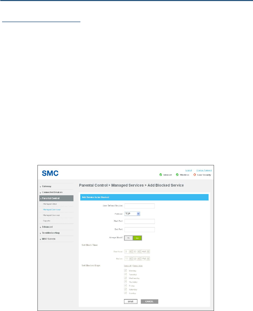
65
SMCD3GNV4 and SMCD3GNV4E Wireless EMTA Gateway Administrator Manual
Configuring Blocked Services
Using the Managed Services page, you can block access to certain services and applications from local
computers.
To define blocked services:
1. In the Blocked Services area on the Managed Services page, click the +ADD button. The Add
Blocked Service page appears (see Figure 40).
2. Complete the fields in the Add Blocked Service page (see Table 18).
3. Click SAVE. The blocked service appears in the Blocked Services table in the Managed Services
page.
4. To edit a blocked service, click the EDIT button next to the blocked service you want to modify, edit
the settings (see Table 18), and click SAVE.
5. To delete a blocked service, click the X next to the service. When a precautionary message appears,
click OK to delete the blocked service or CANCEL to retain it.
Figure 40. Add Blocked Service Page
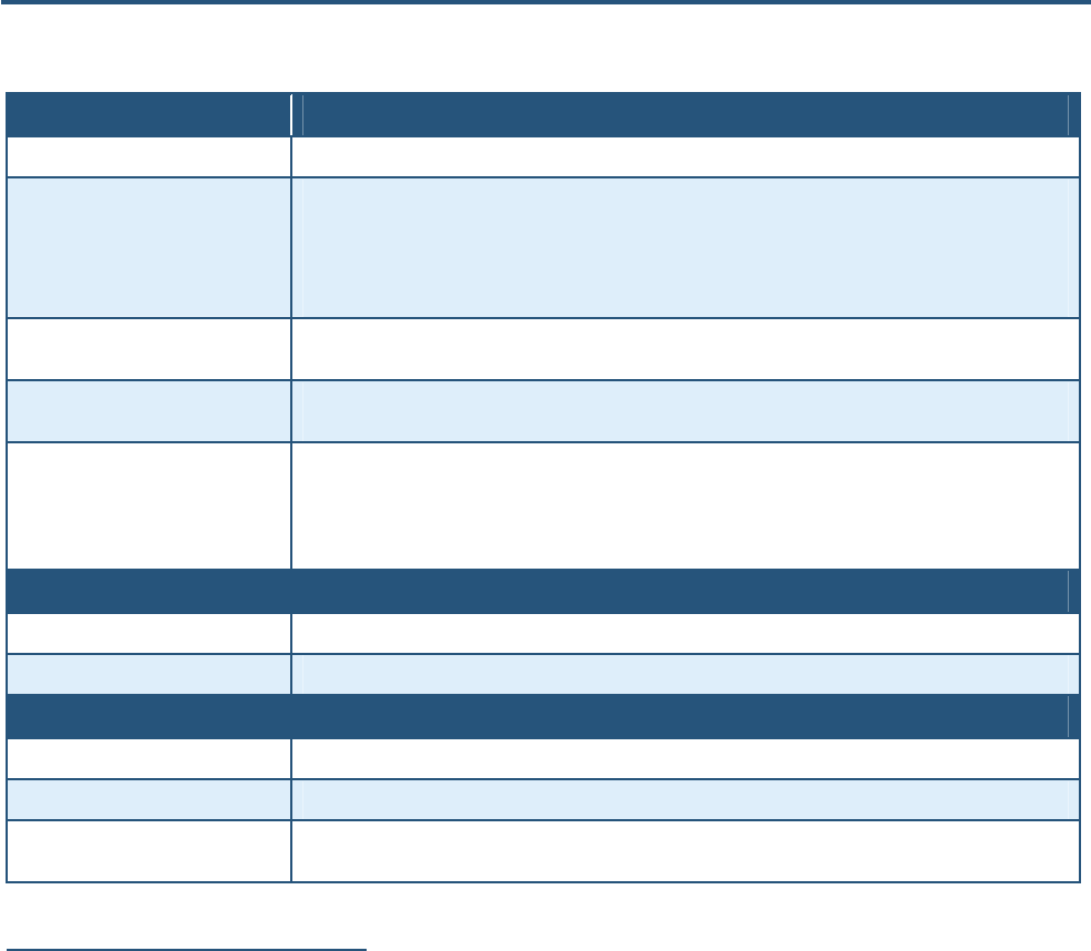
66
SMCD3GNV4 and SMCD3GNV4E Wireless EMTA Gateway Administrator Manual
Table 18. Add Blocked Service Page Options
Option Description
User Defined Service Enter the service you want blocked.
Protocol The type of protocol associated with the service to be blocked. Choices are:
• TCP
• UDP
• TCP/UDP
Start Port Starting port number on which the block will be applied. If necessary, contact the application vendor for this
information.
End Port Ending port number on which the block will be applied. If necessary, contact the application vendor for this
information.
Always Block? Select whether you want the Gateway to always block this service. Choices are
• No = the Gateway does not always block this service. Use Set Block Time and Set Blocked Days to
instruct the Gateway when to block this service.
• Yes = the Gateway always blocks this service until you remove the block.
Set Block Time
Start from If you selected No for Always Block?, select the time when the Gateway is to start blocking this service.
End on If you selected No for Always Block?, select the time when the Gateway is to stop blocking this service.
Set Blocked Days
Select All Click this link to select all seven days. This link is not available if you selected Yes for Always Block?
Select None Click this link to deselect all seven days. This link is not available if you selected Yes for Always Block?
Monday – Sunday Check the check boxes that correspond to the days when you want the Gateway to block this service. These
checkboxes are not available if you selected Yes for Always Block?
Configuring Trusted Computers
Using the Managed Services page, you can define trusted computers that are allowed to access the
blocked services and applications.
To define trusted computers, in the Trusted Computers area on the Managed Services page:
y Click Yes to designate a computer as trusted.
OR
y Click No to designate the computer as not trusted.
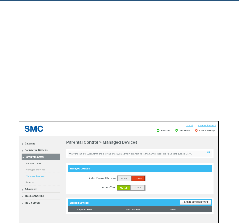
67
SMCD3GNV4 and SMCD3GNV4E Wireless EMTA Gateway Administrator Manual
Managed Devices Page
Path: Parental Control > Managed Devices
The Managed Devices page lets you:
y Enable managed devices – see page 68.
y Allow all or block all access types – see page 68.
After configuring managed devices on this page, use the Enable Managed Devices buttons to enable
or disable the managed devices:
y Click Enabled to enable the devices configured on this page.
y Click Disabled to disable the managed devices configured on this page.
Figure 41. Managed Devices Page

68
SMCD3GNV4 and SMCD3GNV4E Wireless EMTA Gateway Administrator Manual
Enabling or Disabling Access Types
To enable or disable access types, in the Managed Devices area on the Managed Devices page:
y Click Allow All next to Access Type to unblock all access types.
OR
y Click Block All next to Access Type to block all access types.
Adding Allowed or Blocked Devices
If Access Type under Managed Devices on the Managed Devices page is set to Block All, use the
+ ADD ALLOWED DEVICE button in the Allowed Devices area to free devices from being blocked. If
you click this button, an Add Allowed Device similar to the one in Figure 42 appears. For information
about this page, see Table 19.
Similarly, if Access Type under Managed Devices on the Managed Devices page is set to Allow All,
use the + ADD BLOCKED DEVICE button in the Blocked Devices area to block devices. If you click
this button, an Add Blocked Device page similar to the one in Figure 43 appears. For information about
the options on this page, see Table 20.
After you add an allowed or blocked device, you can then:
y Edit the device by clicking the EDIT button next to it, changing the settings, and clicking SAVE.
y Delete the device by clicking the X next to it. When a precautionary message asks whether you
want to delete the device, click OK to delete the device or CANCEL to retain it.
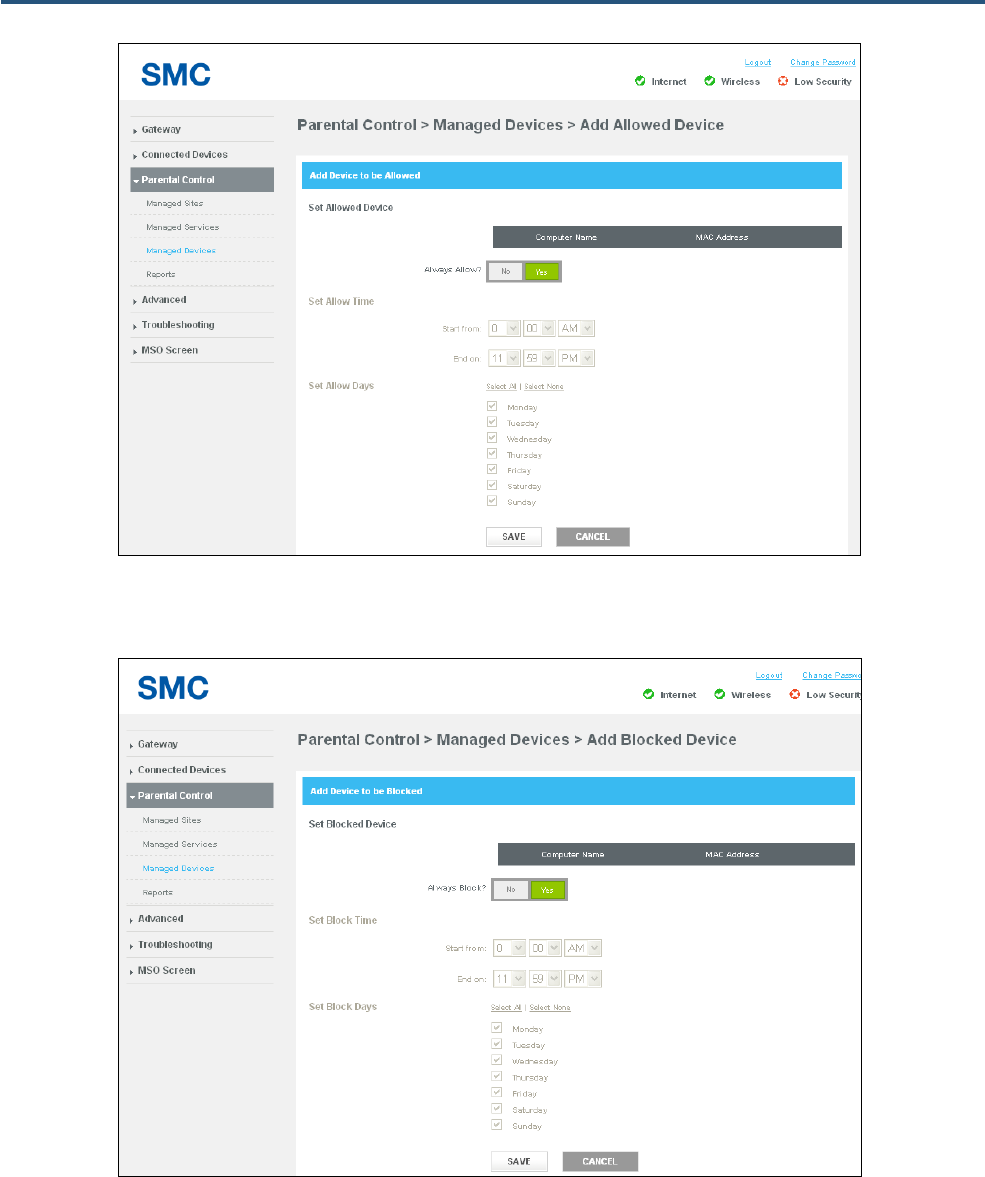
69
SMCD3GNV4 and SMCD3GNV4E Wireless EMTA Gateway Administrator Manual
Figure 42. Add Allowed Device Page
Figure 43. Add Blocked Device Page
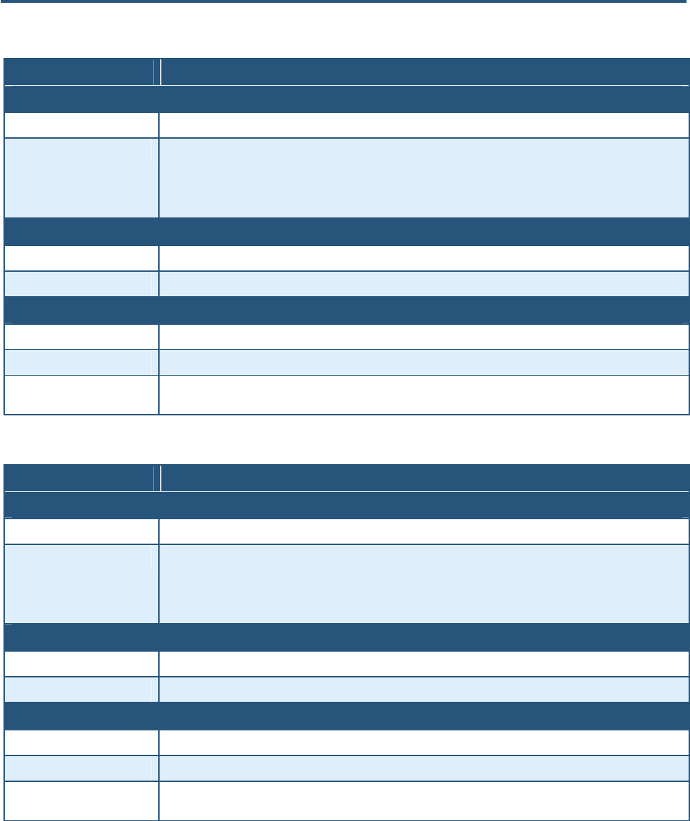
70
SMCD3GNV4 and SMCD3GNV4E Wireless EMTA Gateway Administrator Manual
Table 19. Add Allowed Device Page Options
Option Description
Set Allowed Device
Computer Name/MAC Address Select a device you want to allow.
Always Allow? Select whether you want the Gateway to always allow this device. Choices are
• No = the Gateway does not always allow this device. Use Set Allow Time and Set Allowed Days to instruct the
Gateway when to allow this device.
• Yes = the Gateway always allows this device until you remove the allow.
Set Allow Time
Start from If you selected No for Always Block?, select the time when the Gateway is to start allowing this device.
End on If you selected No for Always Block?, select the time when the Gateway is to stop allowing this device.
Set Allowed Days
Select All Click this link to select all seven days. Link is not available if you select Yes for Always Allow?
Select None Click this link to deselect all seven days. Link is not available if you select Yes for Always Allow?
Monday – Sunday Check the check boxes that correspond to the days when you want the Gateway to allow this device. These
checkboxes are not available if you selected Yes for Always Allow?
Table 20. Add Blocked Device Page Options
Option Description
Set Blocked Device
Computer Name/MAC Address Select a device you want to block.
Always Block? Select whether you want the Gateway to always block this device. Choices are
• No = the Gateway does not always block this device. Use Set Block Time and Set Blocked Days to instruct the
Gateway when to block this device.
• Yes = the Gateway always blocks this device until you remove the block.
Set Block Time
Start from If you selected No for Always Block?, select the time when the Gateway is to start blocking this device.
End on If you selected No for Always Block?, select the time when the Gateway is to stop blocking this device.
Set Blocked Days
Select All Click this link to select all seven days. Link is not available if you select Yes for Always Block?
Select None Click this link to deselect all seven days. Link is not available if you select Yes for Always Block?
Monday – Sunday Check the check boxes that correspond to the days when you want the Gateway to block this device. These
checkboxes are not available if you selected Yes for Always Block?
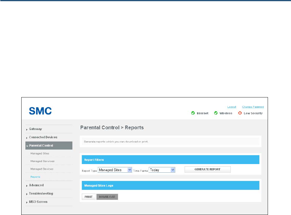
71
SMCD3GNV4 and SMCD3GNV4E Wireless EMTA Gateway Administrator Manual
Reports Page
Path: Parental Control > Reports
The Reports page displays the information form all logs. It also lets you generate parental control
reports that you can print and download as text files.
Figure 44. Reports Page

72
SMCD3GNV4 and SMCD3GNV4E Wireless EMTA Gateway Administrator Manual
Generating Reports
The Report Filters area on the Reports page lets you generate reports based on:
y The type of report you want to generate
y The timeframe that the report is to cover
To generate a report:
1. In the Report Filters area on the Report page, use the Report Type drop-down list to select the
report you want to generate. Choices are:
y All
y Managed Sites
y Managed Services
y Managed Devices
2. Use the Time Frame drop-down list to select the timeframe that the report is to cover. Choices are:
y Today
y Yesterday
y Last week
y Last month
y Last 90 days
3. Click GENERATE REPORT to generate the report on the Reports page using the filters you
specified. If the report has more than one page, use the PREV or NEXT button to move to the
previous or next page.
Printing and Downloading Reports
After you generate a report, you can print it or download it as a text file.
1. To print the report, click PRINT.
2. To download the report, click DOWNLOAD.

73
SMCD3GNV4 and SMCD3GNV4E Wireless EMTA Gateway Administrator Manual
Advanced Page
The Advanced page lets you:
y Enable or disable port forwarding and port triggering – see pages 74 and 77, respectively.
y Configure the Gateway for remote management – see page 80.
y Configure the RIP that the Gateway exchanges with the headend – see page 82.
y Configure a computer for unrestricted two-way Internet access by defining it as a virtual DMZ host -
see page 80.
y Configure QoS – see page 85.
y Configure the Gateway to automatically discover Universal Plug and Play (UPnP)-enabled devices
on the network – see page 87.
y Configure the Gateway’s global VPN settings – see page 89.
y Configure the Gateway’s IPSec tunnel settings – see page 91.
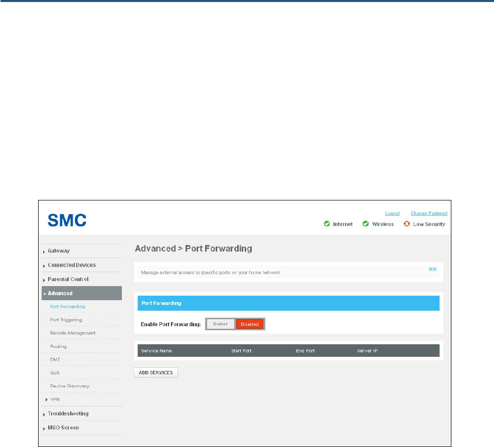
74
SMCD3GNV4 and SMCD3GNV4E Wireless EMTA Gateway Administrator Manual
Port Forwarding Page
Path: Advanced > Port Forwarding
The Port Forwarding page lets you configure the Gateway to provide port-forwarding services that allow
Internet users access predefined services such as HTTP (80), FTP (20/21), and AIM/ICQ (5190) as well
as custom-defined (other) services. You perform port forwarding by redirecting the WAN IP address
and the service port to a local IP address and service port.
Figure 45. Port Forwarding Page
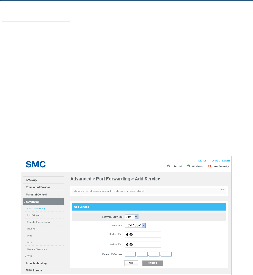
75
SMCD3GNV4 and SMCD3GNV4E Wireless EMTA Gateway Administrator Manual
Adding a Port Forwarding
To add a port forwarding service:
1. In the Port Forwarding page, next to Enable Port Forwarding, click Enabled.
2. Click the ADD SERVICES button below the Port Forwarding table. The Add Service page appears
(see Figure 46).
3. Complete the fields in Add Service page (see Table 21).
4. Click ADD. The port forwarding service appears in the Port Forwarding table in the Port Forwarding
page.
5. To edit a blocked service, click the EDIT button next to the blocked service you want to modify, edit
the settings (see Table 21), and click ADD
6. To delete a port forwarding rule, click the X next to the rule. When a precautionary message appears,
click OK to delete the port forwarding rule or CANCEL to retain it.
Figure 46. Add Service Page
76
SMCD3GNV4 and SMCD3GNV4E Wireless EMTA Gateway Administrator Manual
Table 21. Add Service Page Options
Option Description
Common Services Select the service for which the port forwarding rule is being defined. Choices are:
• AIM
• FTP
• IRC
• HTTP
• Other – if you select this option, enter the name of the service in the Other Service field.
Service Type Select the protocol associated with the service. Choices are:
• TCP/UDP
• TCP
• UDP
Starting Port Enter a starting port on which the service is provided.
Ending Port Enter an ending port on which the service is provided.
Server IP Address Enter the IP address of the LAN PC or server that is running the service.
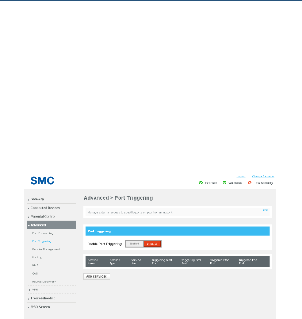
77
SMCD3GNV4 and SMCD3GNV4E Wireless EMTA Gateway Administrator Manual
Port Triggering Page
Path: Advanced > Port Triggering
The Port Triggering page lets you manage external access to specific ports on your home network
using automatic triggering.
When port triggering is enabled, the Gateway monitors outbound traffic. If the Gateway detects traffic
on the specified outbound port, it remembers the IP address of the computer that sent the data, triggers
the incoming port, and then forwards the incoming traffic to the triggering computer.
To use port triggering, you specify which service type and port number you want to track, along with
other related parameters. This allows the Gateway to pass the special applications to the appropriate
ports you specified.
Figure 47. Port Triggering Page
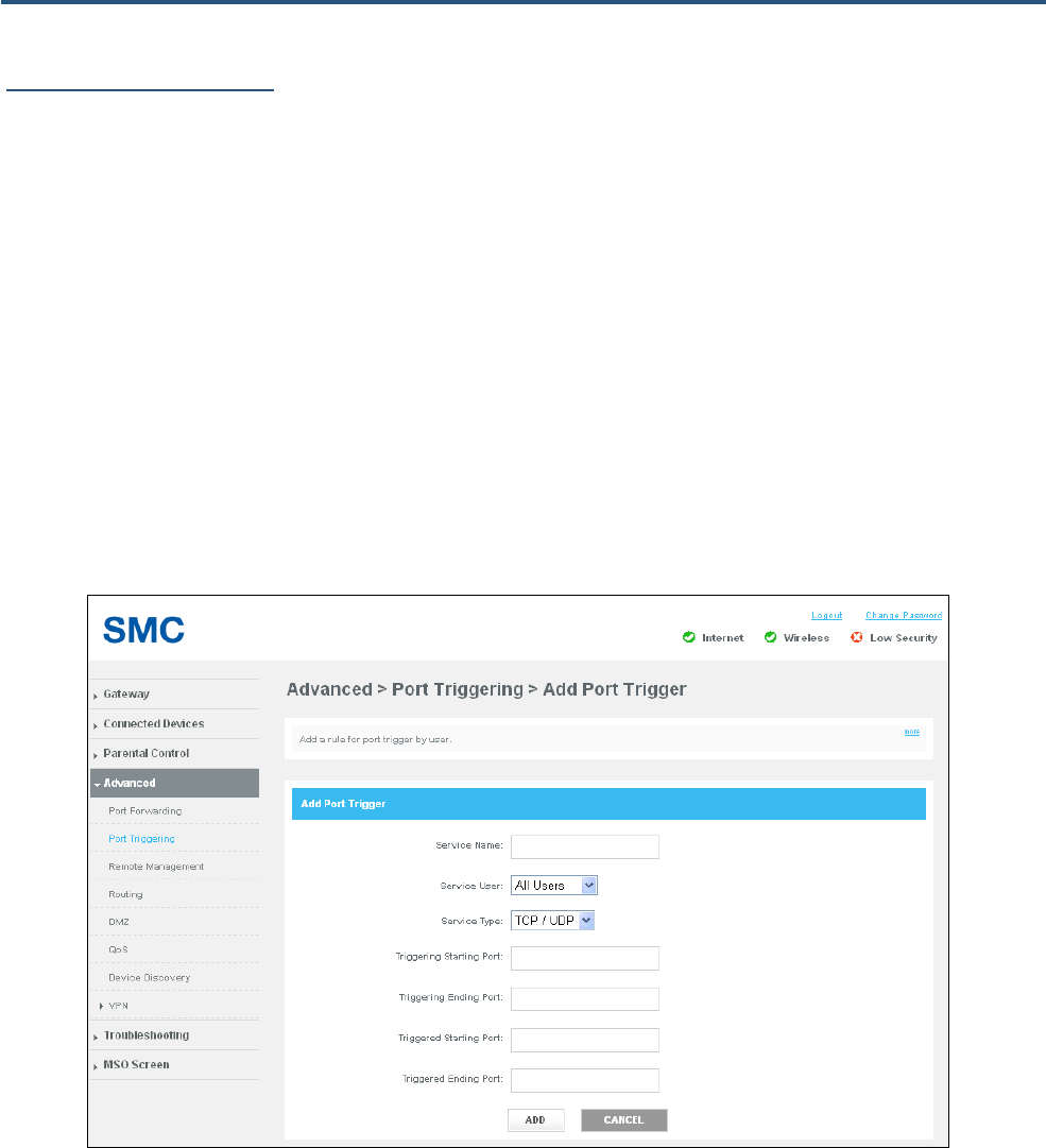
78
SMCD3GNV4 and SMCD3GNV4E Wireless EMTA Gateway Administrator Manual
Adding a Port Triggering
To define a port trigger:
1. In the Port Triggering page, next to Enable Port Triggering, click Enabled.
2. Click the ADD SERVICES button below the Port Triggering table. The Add Port Trigger page
appears (see Figure 48).
3. Complete the fields in Add Port Trigger page (see Table 22).
4. Click ADD. The port trigger appears in the Port Triggering table in the Port Triggering page.
5. To edit a port trigger, click the EDIT button next to the port trigger you want to modify, edit the
settings (see Table 22), and click ADD
6. To delete a port trigger, click the X next to the trigger. When a precautionary message appears, click
OK to delete the port triggering rule or CANCEL to retain it.
Figure 48. Add Port Trigger Page
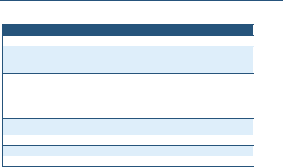
79
SMCD3GNV4 and SMCD3GNV4E Wireless EMTA Gateway Administrator Manual
Table 22. Add Port Trigger Page Options
Option Description
Service Name Name for identifying the trigger. The name is for reference purposes only.
Service User Select a service user from the user list. Choices are:
• All Users
• Single User
Service Type Select the type of protocol you want to use with the trigger. Choices are:
• TCP/UDP
• TCP
• UDP
For example, to track the H.323 protocol, the protocol type should be TCP.
Triggering Starting Point Enter a starting port to be used as the trigger for the special application. For example, to track
H.323 protocol, the starting and ending ports should be 1720.
Triggering Ending Point Enter an ending port to be used as the trigger for the special application.
Triggered Starting Port Enter the starting port to be forwarded.
Triggered Ending Port Enter the ending port to be forwarded.
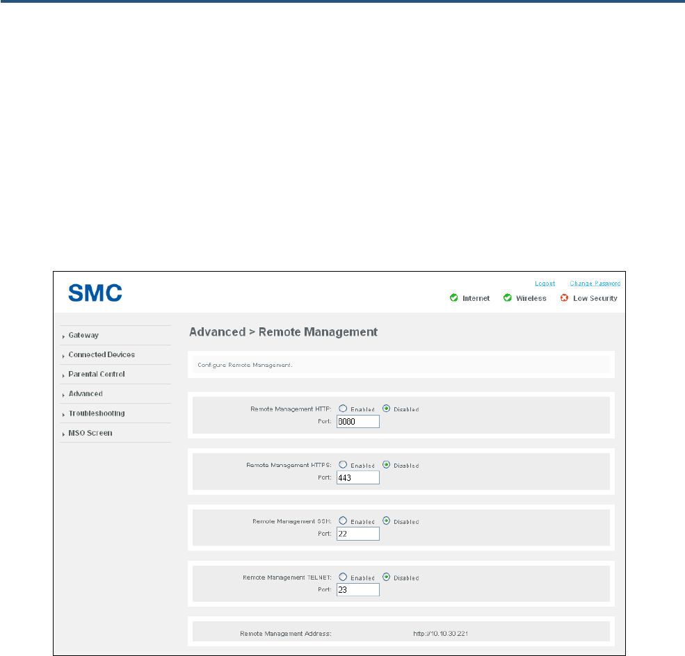
80
SMCD3GNV4 and SMCD3GNV4E Wireless EMTA Gateway Administrator Manual
Remote Management Page
Path: Advanced > Remote Management
Using the Remote Management page, you can configure the Gateway to be managed using a variety of
remote-management methods. You can also specify IP addresses of trusted computers that are
permitted to manage the Gateway remotely. After configuring your settings, click the SAVE button to
apply them.
Figure 49. Remote Management Page
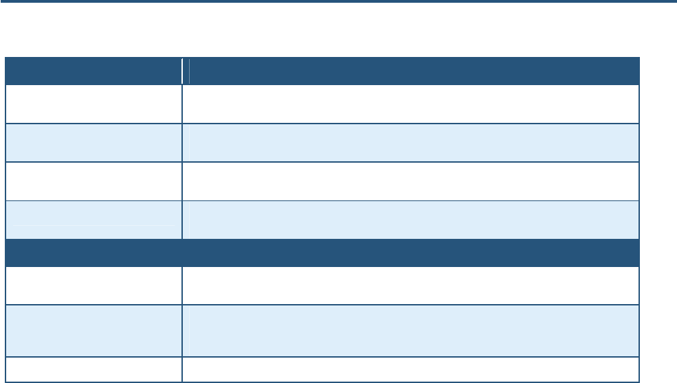
81
SMCD3GNV4 and SMCD3GNV4E Wireless EMTA Gateway Administrator Manual
Table 23. Remote Management Page Options
Option Description
Remote Management HTTP To allow the Gateway to be managed remotely using HTTP, click Enabled and enter the port number
on which the Gateway can be accessed. Default port is 8080.
Remote Management HTTPS To allow the Gateway to be managed remotely using HTTPS, click Enabled and enter the port number
on which the Gateway can be accessed. Default port is 443.
Remote Management SSH To allow the Gateway to be managed remotely using SSH, click Enabled and enter the port number on
which the Gateway can be accessed. Default port is 22.
Remote Management Telnet To allow the Gateway to be managed remotely using Telnet, click Enabled and enter the port number
on which the Gateway can be accessed. Default port is 23.
Remote Access Allowed From
ADD ONE TRUST IP button To designate individual IP addresses as trusted and permitted to perform remote management, enter
the IP address in the IP Address field and then click this button.
ADD RANGE TRUST IP button To designate a range of IP addresses as trusted and permitted to perform remote management, enter
the starting IP address in the Start IP field and the ending range in the End IP field, and then click this
button.
Any Computer To allow any computer to configure the Gateway remotely, regardless of IP address, click this option.
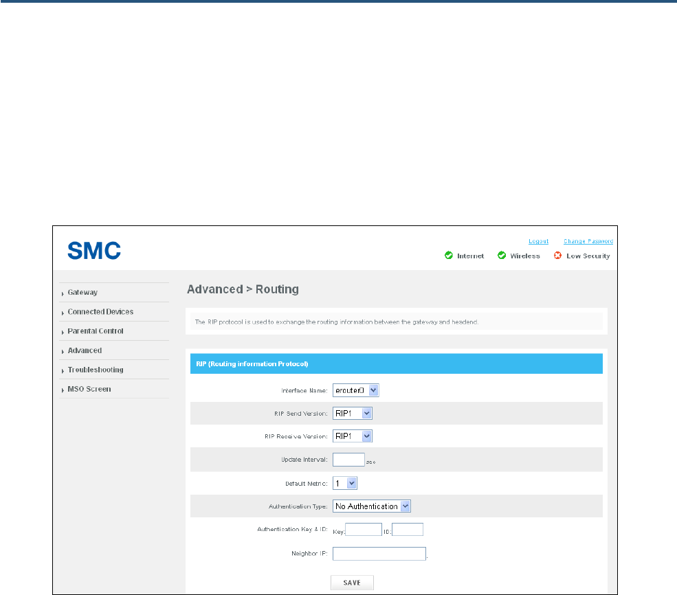
82
SMCD3GNV4 and SMCD3GNV4E Wireless EMTA Gateway Administrator Manual
Routing
Path: Advanced > Routing
Using the Routing page, you can configure the RIP protocol the Gateway uses to exchange routing
information with the headend. After configuring your settings, click the SAVE button to apply them.
Figure 50. Routing Page
83
SMCD3GNV4 and SMCD3GNV4E Wireless EMTA Gateway Administrator Manual
Table 24. Routing Page Options
Option Description
Interface Name Select the Gateway interface on which routing is to be performed.
RIP Send Version Select the format and the broadcasting method of the RIP packets that the Gateway sends. Choices
are:
• RIP1
• RIP2
• RIP1/2
Your selection should match the version supported by other routers on your network.
RIP Receive Version Select the format and the broadcasting method of the RIP packets that the Gateway receives. Choices
are:
• RIP1
• RIP2
• RIP1/2
Your selection should match the version supported by other routers on your network.
Update Interval Specify how often, in seconds, the Gateway sends routing-update messages.
Default Metric Enter a number by which the metric value for the path increases when the Gateway receives a routing
update that includes changes to an entry. Choices are 1 – 15. Default is 1.
Authentication Type Select the authentication mechanism used, if any. Choices are:
• No Authentication = no authentication is used. If you keep this default setting, the Authentication
Key & ID fields are gray and unavailable.
• Simple Password = an authentication method where a clear text password is sent to participating
neighbors on the network. This selection sends the authenticating password over the network,
possible making it available to individuals who can access packets off the network. Do not use this
option as part of your security strategy, Rather, use it to avoid accidental changes to the routing
infrastructure. If you select this setting, the first field in the Authentication Key & ID option becomes
available for entering the password.
• md5 = an authentication method that works much like Simple Password authentication, except that
MD5 does not send the key over the network. Instead, a router uses the MD5 algorithm to produce
a message digest of the key (also called a hash). The router sends the message digest instead of
the key itself, which ensures that no one can eavesdrop on the network and learn keys during
transmission. If you select this setting, the first field in the Authentication Key & ID option becomes
available for entering the key and the second field becomes available for entering the ID.
Authentication Key & ID Specify the appropriate information based on the Authentication Type selected:
• No Authentication = no entry required.
• Simple Password = in the first field, enter the clear-text password to be used for authentication.
The second field requires no entry, and is gray and unavailable.
• md5 = in the first field, enter the MD5-hash password. In the second field, enter the Key Identifier
that identifies the key used to create the authentication data for this message.
Neighbor IP Enter the IP address of the Gateway’s RIP neighbor router.
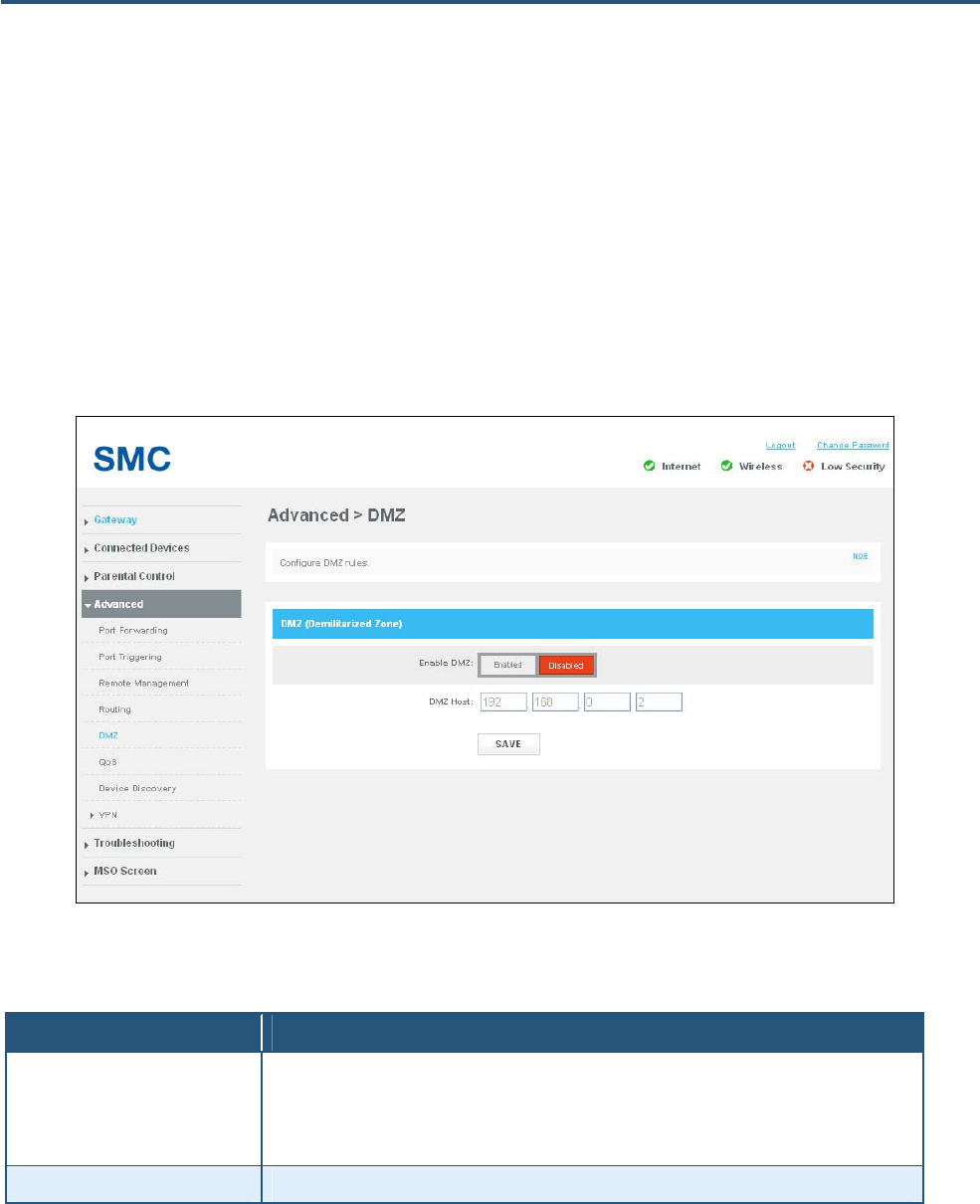
84
SMCD3GNV4 and SMCD3GNV4E Wireless EMTA Gateway Administrator Manual
DMZ Page
Path: Advanced > DMZ
If you have a local client computer that cannot run an Internet application properly behind the firewall,
you can configure the computer for unrestricted two-way Internet access by defining it as a Virtual DMZ
host. A DMZ allows a single computer on your LAN to expose its ports to the Internet. When doing this,
the exposed computer is no longer “behind” the firewall. Therefore, placing a computer in the DMZ
should be considered temporary because the firewall is no longer able to provide any security to it.
Figure 51. DMZ Page
Table 25. DMZ Page Options
Option Description
Enable DMZ Enables or disables the Gateway’s DMZ setting.
• Enabled = Gateway’s DMZ feature is enabled.
• Disabled = Gateway’s DMZ feature is disabled. This selection makes the SMZ Host field
unavailable.
DMZ Host Enter the IP addresses of the computer to be used as the DMZ server.
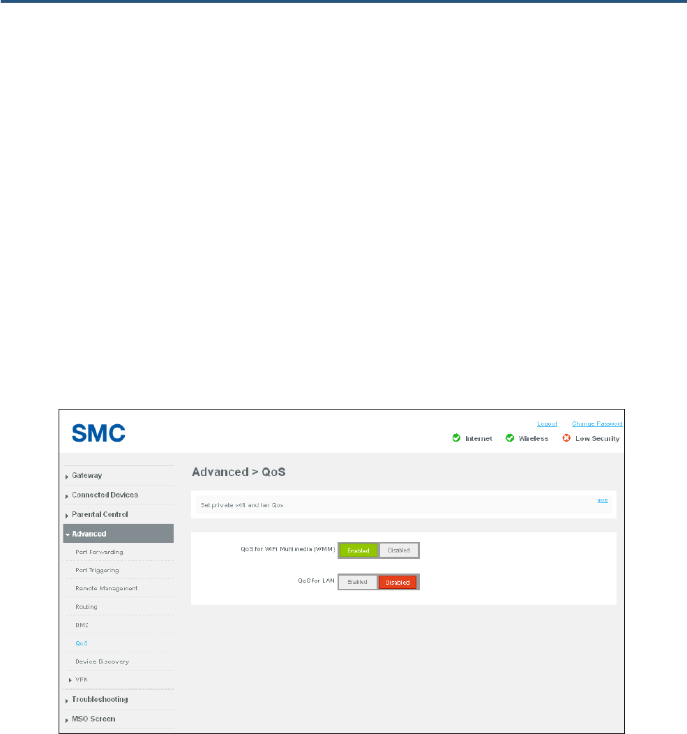
85
SMCD3GNV4 and SMCD3GNV4E Wireless EMTA Gateway Administrator Manual
QoS Page
Path: Advanced > QoS
The QoS page lets you configure the Gateway to deliver better resource reservation control. Wireless
networks offer an equal opportunity for all devices to transmit data from any type of application.
Although this is acceptable for most applications, multimedia audio and video applications are
particularly sensitive to the delay and throughput variations that result from this “equal opportunity”
wireless access method. For multimedia applications to run well over a wireless network, a Quality of
Service (QoS) mechanism is required to prioritize traffic types and provide an “enhanced opportunity”
wireless access method.
The QoS page lets you enable or disable QoS settings. After making your selections, click the SAVE
button to apply them. You can change QoS settings without having to reboot the Gateway.
Figure 52. QoS Page
86
SMCD3GNV4 and SMCD3GNV4E Wireless EMTA Gateway Administrator Manual
Table 26. QoS Page Options
Option Description
QoS for WiFi Multimedia (WMM) Enables or disables QoS for WMM. Choices are:
• Enabled = QoS is enabled for WMM.
• Disabled = QoS is disabled for WMM.
QoS for LAN Enables or disables QoS for WMM. Choices are:
• Enabled = QoS is enabled for WMM.
• Disabled = QoS is disabled for WMM.
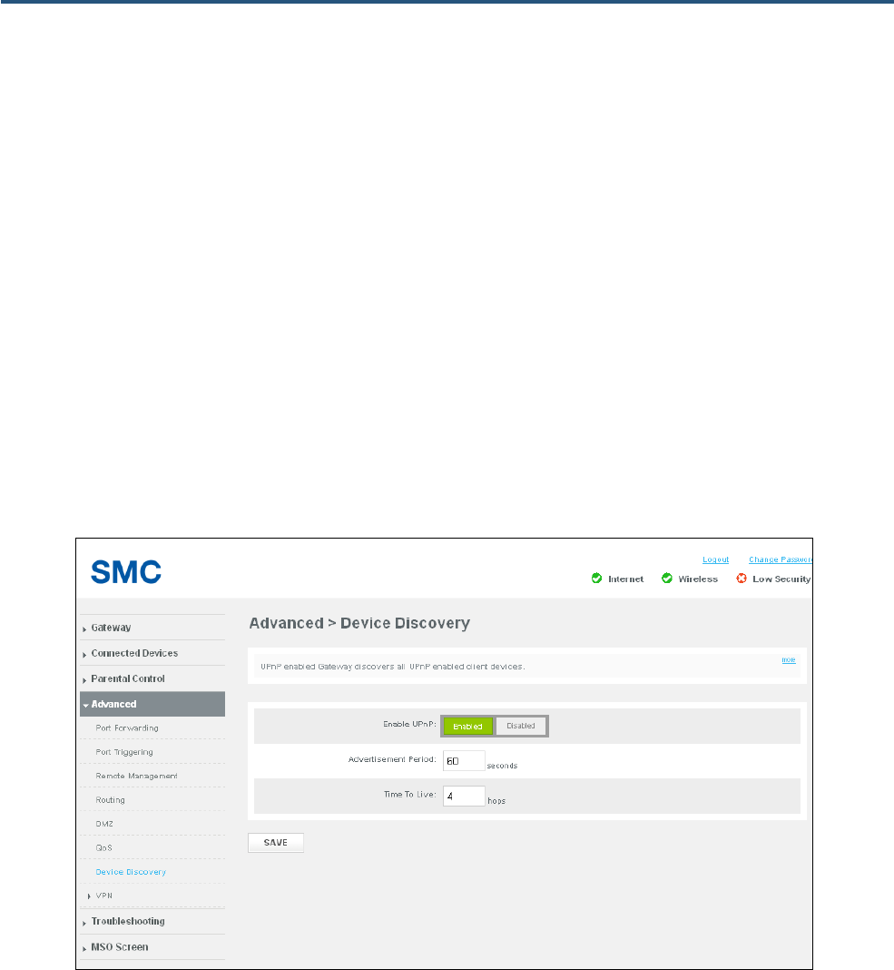
87
SMCD3GNV4 and SMCD3GNV4E Wireless EMTA Gateway Administrator Manual
Device Discovery Page
Path: Advanced > Device Discovery
Universal Plug and Play (UPnP) is an architecture that allows for dynamic connectivity between devices
on a network. The goal of UPnP is to support zero-configuration, "invisible" networking of devices
including intelligent appliances, PCs, printers and other smart devices using standard protocols.
Using UPnP, devices can add themselves to a network dynamically, without requiring user intervention
or configuration. A UPnP-enabled device can obtain an IP address, advertise its capabilities, learn
about other connected UPnP devices, and then communicate directly with those devices. The same
device can end its connection cleanly when it wishes to leave the UPnP community.
Using the Device Discovery page, the Gateway can discover all UPnP-enabled devices on the network.
After making your selections, click the SAVE button to apply them.
Figure 53. Device Discovery Page
88
SMCD3GNV4 and SMCD3GNV4E Wireless EMTA Gateway Administrator Manual
Table 27. Device Discovery Page Options
Option Description
Enable UPnP Determines whether the Gateway’s UPnP capabilities are enabled or disabled. Choices are:
• Enabled = enables the Gateway’s UPnP capabilities.
• Disabled = disables the Gateway’s UPnP capabilities.
Advertisement Period Specify how often, in seconds, the Gateway broadcasts its UPnP information. This value can
range from 1 to 2147483648 seconds. Short durations ensure that control points have current
device status at the expense of additional network traffic. Long durations can compromise the
freshness of the device status, but can significantly reduce network traffic.
Time To Live Configure the number of hops (steps) for the advertisement time to live. The time to live for the
advertisement is measured in hops for each UPnP packet sent. The time to live hop count is the
number of steps a broadcast packet is allowed to propagate for each UPnP advertisement
before it disappears. The number of hops can range from 1 to 255. The default setting should be
fine for most home networks. If some of your devices are not being updated or reached
correctly, you can increase this value slightly.
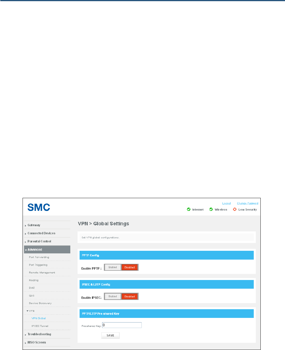
89
SMCD3GNV4 and SMCD3GNV4E Wireless EMTA Gateway Administrator Manual
VPN Global Page
Path: Advanced > VPN > Global
A Virtual Private Network (VPN) is a technology designed to increase the security of information
transferred over the Internet. A VPN creates a private encrypted tunnel from the user's computer,
through the local wireless network, through the Internet, all the way to the corporate servers and
database.
The Gateway supports the Internet Protocol Security (IPSec) to secure IP traffic. IPSec builds “virtual
tunnels” between a local and remote subnet for secure communication between two networks. This
connection is commonly known as a Virtual Private Network (VPN).
Alternatively, tunneling protocols such as Point-to-Point Tunneling Protocol (PPTP) and Layer Two
Tunneling Protocol (L2TP) can be used to achieve a secure connection (such as to a corporate LAN)
over the Internet. These tunneling protocols can optionally be secured themselves using IPSec.
Using the Global settings page, you can enable or disable the Gateway’s VPN settings.
Figure 54. Global Settings Page
90
SMCD3GNV4 and SMCD3GNV4E Wireless EMTA Gateway Administrator Manual
Table 28. Global Settings Page Options
Option Description
Enable PPTP Lets you enable or disable PPTP tunneling.
Enable IPSEC Lets you enable or disable L2TP tunneling.
Pre-shared Key Enter a “pass code.” This pass code must be the same at both the local and the remote side.
Both ends of the tunnel must use the same key; otherwise, the VPN tunnel cannot be
established.
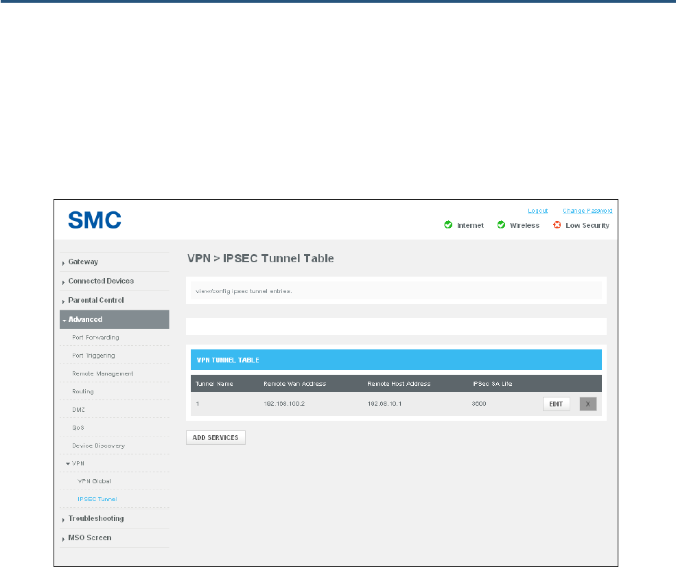
91
SMCD3GNV4 and SMCD3GNV4E Wireless EMTA Gateway Administrator Manual
IPSEC Tunnel Table Page
Path: Advanced > VPN > IPSEC Tunnel
The IPSEC Tunnel page lets you configure tunnels on the Gateway.
Figure 55. IPSEC Tunnel Table Page
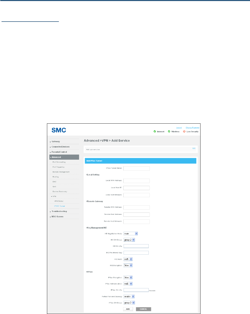
92
SMCD3GNV4 and SMCD3GNV4E Wireless EMTA Gateway Administrator Manual
Adding IPSec Tunnels
To add IPSec tunnels from the IPSEC Tunnel page:
1. Click :the ADD SERVICES button. The Add Service page appears (see Figure 46).
2. Complete the fields in the Add Service page (see ).
3. Click ADD.
4. To edit an IPSec tunnel, click the EDIT button next to the tunnel you want to modify, edit the settings
(see Table 22), and click ADD
5. To delete an IPSec tunnel, click the X next to the tunnel. When a precautionary message appears,
click OK to delete the tunnel or CANCEL to retain it.
Figure 56. Add Service Page

93
SMCD3GNV4 and SMCD3GNV4E Wireless EMTA Gateway Administrator Manual
Table 29. Add Service Page Options
Option Description
IP Sec Tunnel Name Enter a unique name for the IPSec tunnel you are creating.
#Local Setting
Local WAN Address Enter the WAN IP address of the local host.
Local Host IP Enter the IP address of the local host.
Local Host Netmask Enter the netmask of the local host.
#Remote Gateway
Remote WAN Address Enter the WAN IP address of the remote gateway other end of the VPN tunnel.
Remote Host Address Enter the IP address of the remote host at the other end of the VPN tunnel.
Remote Host Netmask Enter the netmask of the remote host other end of the VPN tunnel.
#Key Management
IKE Negotiation Mode Select the IKE operating mode. Choices are:
• Main = creates an encrypted channel before exchanging the identities.
• Aggressive = quicker than Main Mode, exchanges endpoint IDs in “clear text”, while performing
Diffie-Hellman (DH) exchange and establishing the secure channel. Aggressive Mode is less secure than
Main Mode.
IKE DH Group Select the DH group that will produce the secret shared value. The strength of the technique is that it allows
participants to create the secret value over an unsecured medium without passing the secret value through the
wire. You can select from three DH groups. The size of the prime modulus used in each group's calculation
differs as follows:
• Group 2 = D-H Group 2 algorithm is used for the Diffie-Hellman Key Exchange. DH Group 2 uses a 1024-bit
encryption.
• Group 5 = D-H Group 5 algorithm is used for the Diffie-Hellman Key Exchange. DH Group 5 uses a 1536-bit
encryption.
• Group 6 = D-H Group 6 algorithm is used for the Diffie-Hellman Key Exchange. DH Group 6 offers the
highest key size and the highest level of security.
IKE Pre-shared Key Enter a “pass code”. The pass code must be the same at both the local and the remote side. Both ends of the
tunnel must use the same key; otherwise, the VPN tunnel cannot be established.
IKE Hash Checks that the data has not changed in transmission. Both ends of the tunnel must use the same setting;
otherwise, the VPN tunnel cannot be established. Choices are:
• md5 = faster than SHA, but less secure.
• SHA1 = a one-way hashing algorithm that produces a 160-bit digest. SHA is more secure than MD5
IKE Encryption Encryption algorithm used during the Authentication phase. Choices are
• 3des = triple DES is a symmetric strong encryption algorithm that is compliant with the OpenPGP standard.
It is the application of DES standard, where three keys are used in succession to provide additional
security.
• aes = Advanced Encryption Standard offers the highest standard of security. The effective key lengths that
can be used with AES are 128, 192, and 256 bits. The higher the bit rate, the stronger the encryption but the
trade-off is lower throughput. More secure than 3DES.
Both ends of the tunnel must use the same setting; otherwise, the VPN tunnel cannot be established.
#IP Sec
94
SMCD3GNV4 and SMCD3GNV4E Wireless EMTA Gateway Administrator Manual
Option Description
IPSec Encryption Select the authentication algorithm used to encrypt packet data. Choices are
• 3des = more secure method than DES, but with lower throughput.
• aes = more secure than 3DES. The higher the bit rate, the stronger the encryption but the trade-off is lower
throughput.
• null = no authentication used..
Both ends of the tunnel must use the same setting; otherwise, the VPN tunnel cannot be established. This field
is gray and unavailable if AH is selected for IPSec operation.
IPSec Authentication Authentication method used when ESP is selected for IPSec Operation. Both ends of the tunnel must use the
same setting; otherwise, the VPN tunnel cannot be established. Choices are:
• md5 = a one-way hashing algorithm that produces a 128-bit digest. (default)
• sha = a one-way hashing algorithm that produces a 160-bit digest. SHA is more secure than MD5.
IPSec SA Life Enter the number of seconds for the IPSec lifetime. This is the period of time that can pass before establishing
a new IPSec security association (SA) with the remote endpoint.
Perfect Forward Secrecy Ensures that a session key derived from a set of long-term public and private keys will not be compromised if
one of the (long-term private keys is compromised in the future. Both sides of the VPN must be able to support
Perfect Forward Secrecy in order for it to work.
• enable = ensures the same key will not be generated again, forcing a new D-H key exchange.
• disable = feature is disabled.
IPSec DH Group Select the D-H group used during the VPN negotiation stage. Choices are:
• group 2 = provides basic security and good performance.
• group 5 = like group 2. Actual initialization and rekey speed depend on a number of factors.
• group 6 = offers the fastest performance. If performance times are a problem for your network, change to a
lower DH group.

95
SMCD3GNV4 and SMCD3GNV4E Wireless EMTA Gateway Administrator Manual
Troubleshooting Page
The Troubleshooting page lets you:
y Download and print system logs – see page 96.
y Use diagnostic tools to troubleshoot problems – see page 98.
y Restore or reboot the Gateway – see page 100.
y Change the password used to log in to the Web management interface – see page 101.
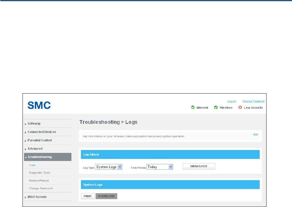
96
SMCD3GNV4 and SMCD3GNV4E Wireless EMTA Gateway Administrator Manual
Logs Page
Path: Troubleshooting > Logs
The Logs page lets you view logs related to Gateway’s performance and system operation. After you
display a log, you can print the log or download it as a text file.
Figure 57. Example of Logs Page

97
SMCD3GNV4 and SMCD3GNV4E Wireless EMTA Gateway Administrator Manual
Generating Logs
The Log Filters area on the Logs page lets you generate logs based on:
y The type of log you want to generate
y The timeframe that the log is to cover
To generate a log:
1. In the Log Filters area on the Logs page, use the Log Type drop-down list to select the log you
want to generate. Choices are:
y System Logs
y Event Logs
y Firewall Logs
2. Use the Time Frame drop-down list to select the timeframe that the log is to cover. Choices are:
y Today
y Yesterday
y Last week
y Last month
y Last 90 days
3. Click SHOW LOGS to generate the log On the Logs page using the filters you specified. If the log
consists of more than one page, use the PREV or NEXT button to move to the previous or next page,
Printing or Downloading the Log
After you generate a log, you can print it or download it as a text file.
1. To print the log, click PRINT.
2. To download the log, click DOWNLOAD.
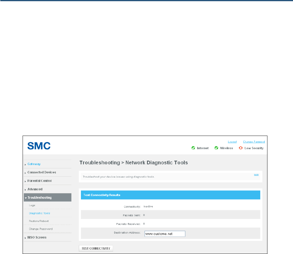
98
SMCD3GNV4 and SMCD3GNV4E Wireless EMTA Gateway Administrator Manual
Network Diagnostic Tools Page
Path: Troubleshooting > Diagnostic Tools
There may be times when you encounter a problem trying to reach a certain destination. If you examine
the Gateway’s configuration and operation and everything looks fine, the problem might be with a router
up the line from the Gateway or with the line itself.
To help you identify such issues, use the Network Diagnostic Tools page to test connectivity to a
destination or IP address.
Figure 58. Network Diagnostic Tools Page

99
SMCD3GNV4 and SMCD3GNV4E Wireless EMTA Gateway Administrator Manual
Testing Connectivity to a Destination Address
To test the Gateway’s connectivity to a destination address:
1. In the Network Diagnostic Tools page, under Test Connectivity Results, enter a destination
address in the Destination Address field.
Note: This procedure assumes that the destination address you enter is valid and operational.
2. Click the TEST CONNECTIVITY button. The Connectivity counter shows whether the path is active
or inactive. The Packets Sent and Packets Received counters show the number of packets sent and
received during the test.
If the test succeeds, the destination you are having difficulty reaching is alive and physically reachable.
If there are routers between the Gateway and the destination and you are having difficulty reaching, the
problem might be at one of the routers.
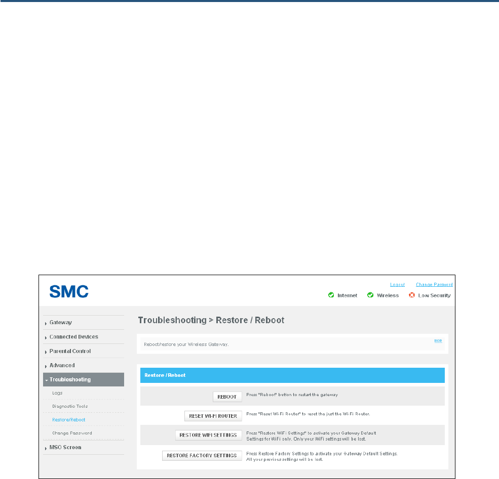
100
SMCD3GNV4 and SMCD3GNV4E Wireless EMTA Gateway Administrator Manual
Restore/Reboot Page
Path: Troubleshooting > Restore/Reboot
The Restore / Reboot page provides buttons for performing the following activities:
y RESET = restarts the Gateway, but keeps overrides made to the factory default settings.
y RESET WI-FI Router = resets the Wi-Fi router without affecting the Gateway.
y RESTORE WIFI SETTINGS = removes overrides made to the Gateway’s wireless settings only and
returns the wireless settings to their default values. All other settings remain unchanged.
y RESTORE FACTORY SETTINGS = removes overrides made to all Gateway settings and returns
the Gateway to its factory default values.
Figure 59. Restore / Reboot Page

101
SMCD3GNV4 and SMCD3GNV4E Wireless EMTA Gateway Administrator Manual
Change Password Page
Path : Troubleshooting > Change Password or click Change Password at the top-right of the Web
management interface
The Change Password page lets you change the password used to log in to the Gateway’s Web
interface. For security, we recommend you change the default log in password the first time you log in to
the Web management interface to protect the Gateway from being tampered with.
Figure 60. Change Password Page
Table 30. Change Password Options
Option Description
Current Password Enter the current case-sensitive password. For security purposes, every typed character is
masked as a dot (y). The default password is not shown for security purposes.
New Password Enter the new case-sensitive password you want to use. A password can contain up to 32
alphanumeric characters and spaces. Spaces count as password characters. For security
purposes, every typed character is masked as a dot (y).
Re-enter New Password Enter the same case-sensitive password you typed in the New Password field. For security
purposes, every typed character is masked as a dot (y).

102
SMCD3GNV4 and SMCD3GNV4E Wireless EMTA Gateway Administrator Manual
MSO Screens
The last menu in the right pane is MSO Screen. This menu contains configuration pages that
administrators will find helpful when managing the Gateway. Most of the pages are read-only, although
some let you configure Gateway settings.
The MSO screens are:
y Basic HW Info – shows basic hardware information about the cable modem. See page 103.
y Event Log – shows the entries in the Gateway’s event log. See page 104.
y CM State – shows the Gateway’s cable modem state and associated information. See page 105.
y Basic Wan Status – shows RF downstream, RF upstream, and RF status statistics. See page 106.
y Product Detail – shows the Gateway’s cable modem and WAN status. See page 107.
y DHCP – shows software version/provisioning mode, cable modem DHCP parameters, DHCP cable
modem status, and MTA DHCP parameters. See page 108.
y MTA – shows error codewords and enterprise Management Information Bases (MIBs), and lets you
initiate GR909 tests. See page 109.
y Telnet/SSN – enables or disables Telnet and SSH requests and displays Telnet and SSH
information. See page 111.
y System Config – enables or disables the Gateway’s wireless functions. See page 112.
To return to the previous set of menus and submenus, click Gateway WEB in the left pane. The right
pane also has a Logout link that exits you from the Web management interface.
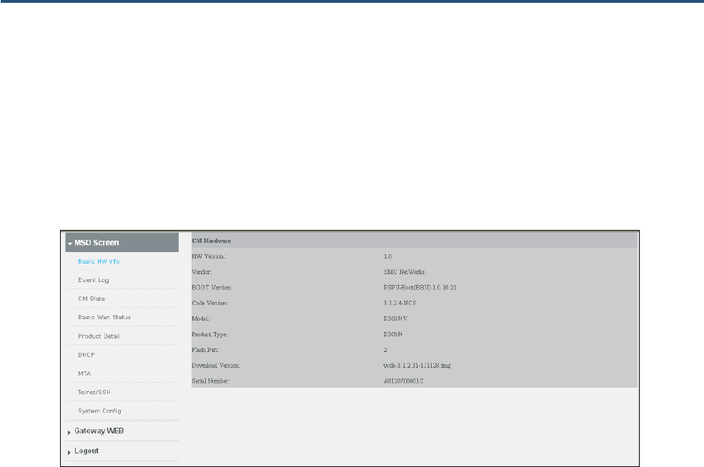
103
SMCD3GNV4 and SMCD3GNV4E Wireless EMTA Gateway Administrator Manual
CM Hardware Page
Path: MSO Screen > Basic HW Info
The CM Hardware page is a read-only page that shows basic hardware information about the cable
modem. .
Figure 61. CM Hardware Page
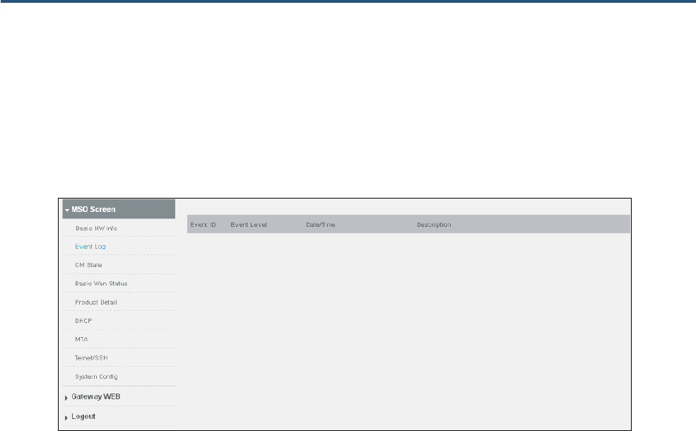
104
SMCD3GNV4 and SMCD3GNV4E Wireless EMTA Gateway Administrator Manual
Event Log Page
Path: MSO Screens > Event Log
The Event Log page is a read-only page that shows the entries in the Gateway’s event log.
Figure 62. Event Log Page
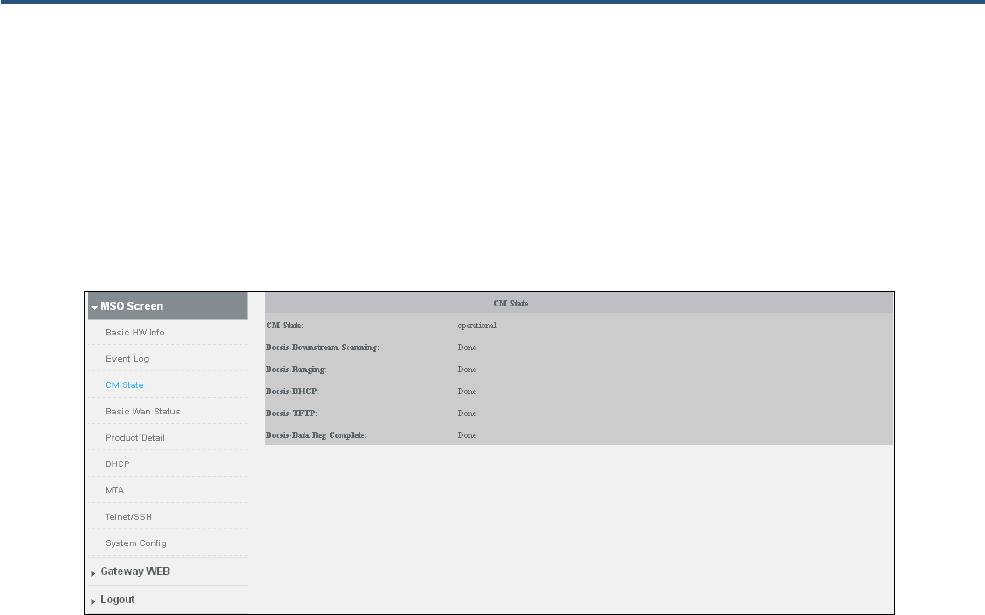
105
SMCD3GNV4 and SMCD3GNV4E Wireless EMTA Gateway Administrator Manual
CM State Page
Path: MSO Screen > CM State
The CM State page is a read-only page that shows information about the state of the cable modem.
Figure 63. CM State Page
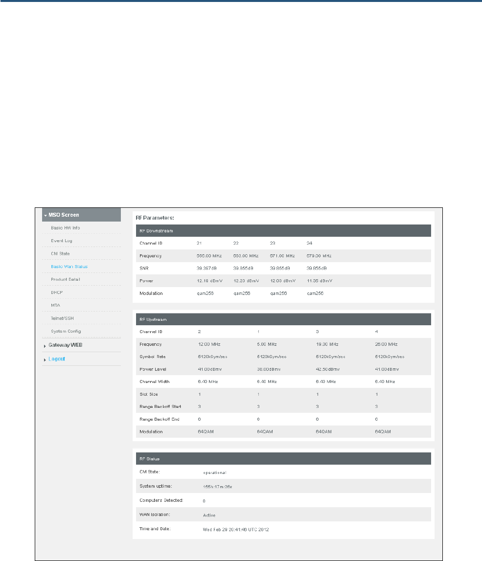
106
SMCD3GNV4 and SMCD3GNV4E Wireless EMTA Gateway Administrator Manual
RF Parameters Page
Path: MSO Screen > Basic Wan Status
The RF Parameters page is a read-only page that is organized into three sections:
y RF Downstream shows information abut the radio-frequency downstream connection.
y RF Upstream shows information abut the radio-frequency upstream connection.
y RF Status shows the Gateway’s radio-frequency status.
Figure 64. RF Parameters Page
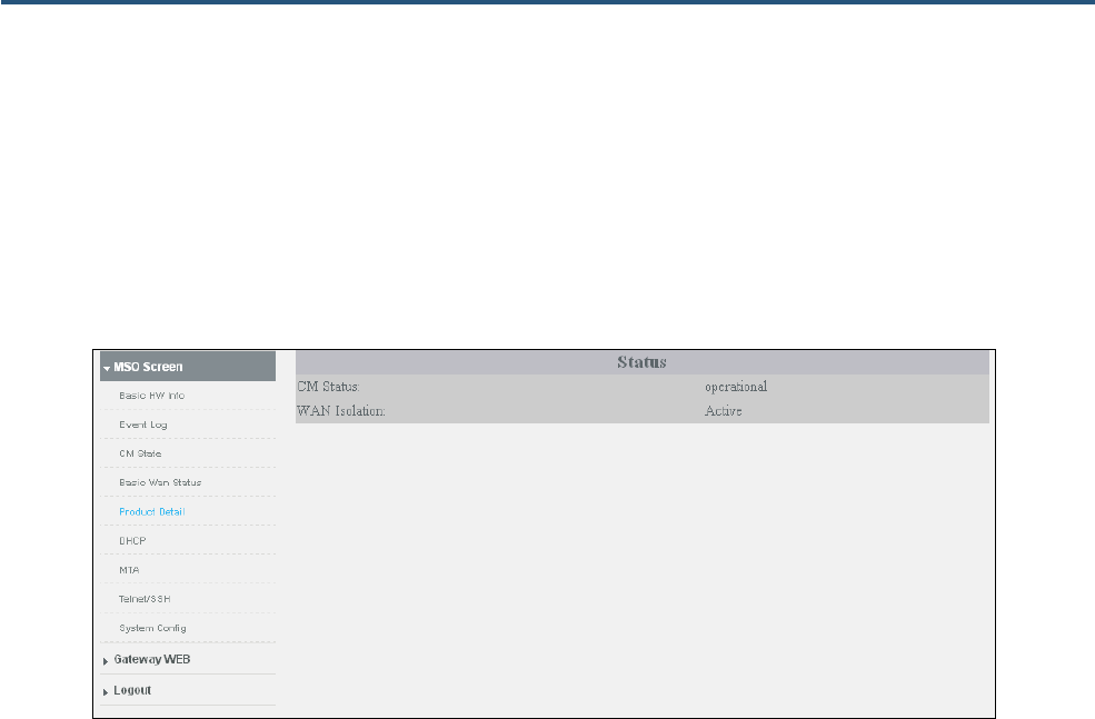
107
SMCD3GNV4 and SMCD3GNV4E Wireless EMTA Gateway Administrator Manual
Status Page
Path: MSO Screen > Product Detail
The Status page is a read-only page that shows the status of the Gateway’s cable modem and WAN
isolation.
Figure 65. Status Page
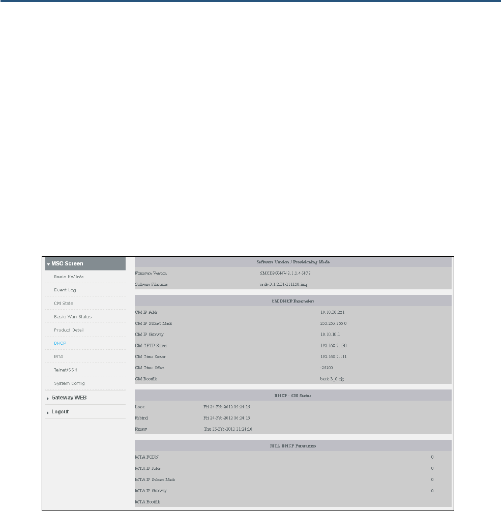
108
SMCD3GNV4 and SMCD3GNV4E Wireless EMTA Gateway Administrator Manual
DHC Page
Path: MSO Screen > DHCP
The DHCP page is a read-only page that is organized into four sections:
y Software Version/Provisioning Mode shows the Gateway firmware version and software
filename.
y CM DHCP Parameters shows the DHCP settings for the cable modem.
y DHCP – CM Status shows the DHCP status for the cable modem.
y MTA DHCP Parameters shows the DHCP settings for the Message Transfer Agent (MTA).
Figure 66. DHCP Page

109
SMCD3GNV4 and SMCD3GNV4E Wireless EMTA Gateway Administrator Manual
MTA Page
Path: MSO Screen > MTA
The MTA page is organized into three sections:
y Error Codewords unerrored, correctable, and uncorrectable number of codewords.
y Enterprise MIBs shows the Enterprise Management Information Bases used by the Gateway.
y GR909 Test consists of a suite of standards-based electrical tests that can be used to identify
several common issues with VoIP connections, such as an off-hook phone or voltage on a VoIP line.
Using the GR909 Test area, you can perform a GR909 test. The GR-909 test actually consists of
five tests:
– Hazardous Potential and Foreign Electrical Motive Force tests detect voltages that should not
be on the telephone line(s).
– Resistive Faults Test detects shorts on the telephone lines, including possible shorts to ground
and shorts that can result from the two phone line wires coming in contact. This condition can
happen from corroded jacks or with inexpensive splitters.
– Receiver Off Hook test searches for devices on premise that may be keeping the line open,
such as a telephone or fax machine.
– Ringers Test measures the electrical load on the line, typically referred as the REN Ringer
Equivalency Number. This test can fail if there are too many devices connected to the line or if
the test does not detect any load, suggesting no operable device connected on the line.
To perform a GR909 test:
1. From the Line Number drop-down list, select the line on which you want to perform the test.
2. Click the Start TEST button to begin the tests. At the end of testing, the results are displayed.
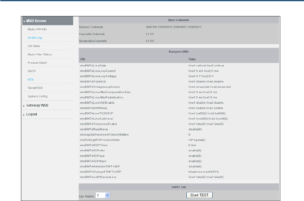
110
SMCD3GNV4 and SMCD3GNV4E Wireless EMTA Gateway Administrator Manual
Figure 67. MTA Page
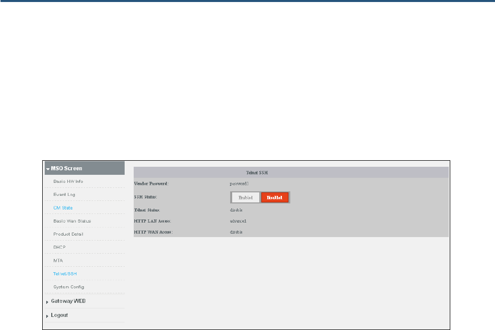
111
SMCD3GNV4 and SMCD3GNV4E Wireless EMTA Gateway Administrator Manual
Telnet/SSH Page
Path: MSO Screen > Telnet/SSH
The Telnet/SSH page shows information about the Gateway’s Telnet and SSH status. Enabled and
Disabled buttons are provided for enabling or disabling the Gateway’s SSH functionality.
Figure 68. Telnet/SSH Page
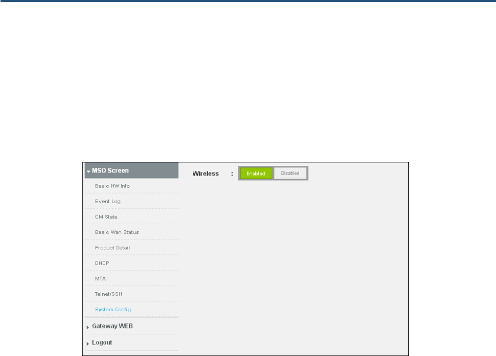
112
SMCD3GNV4 and SMCD3GNV4E Wireless EMTA Gateway Administrator Manual
System Config Page
Path: MSO Screen > System Config
The System Config page provides Enabled and Disabled buttons for enabling or disabling the
Gateway’s wireless functionality.
Figure 69. System Config Page
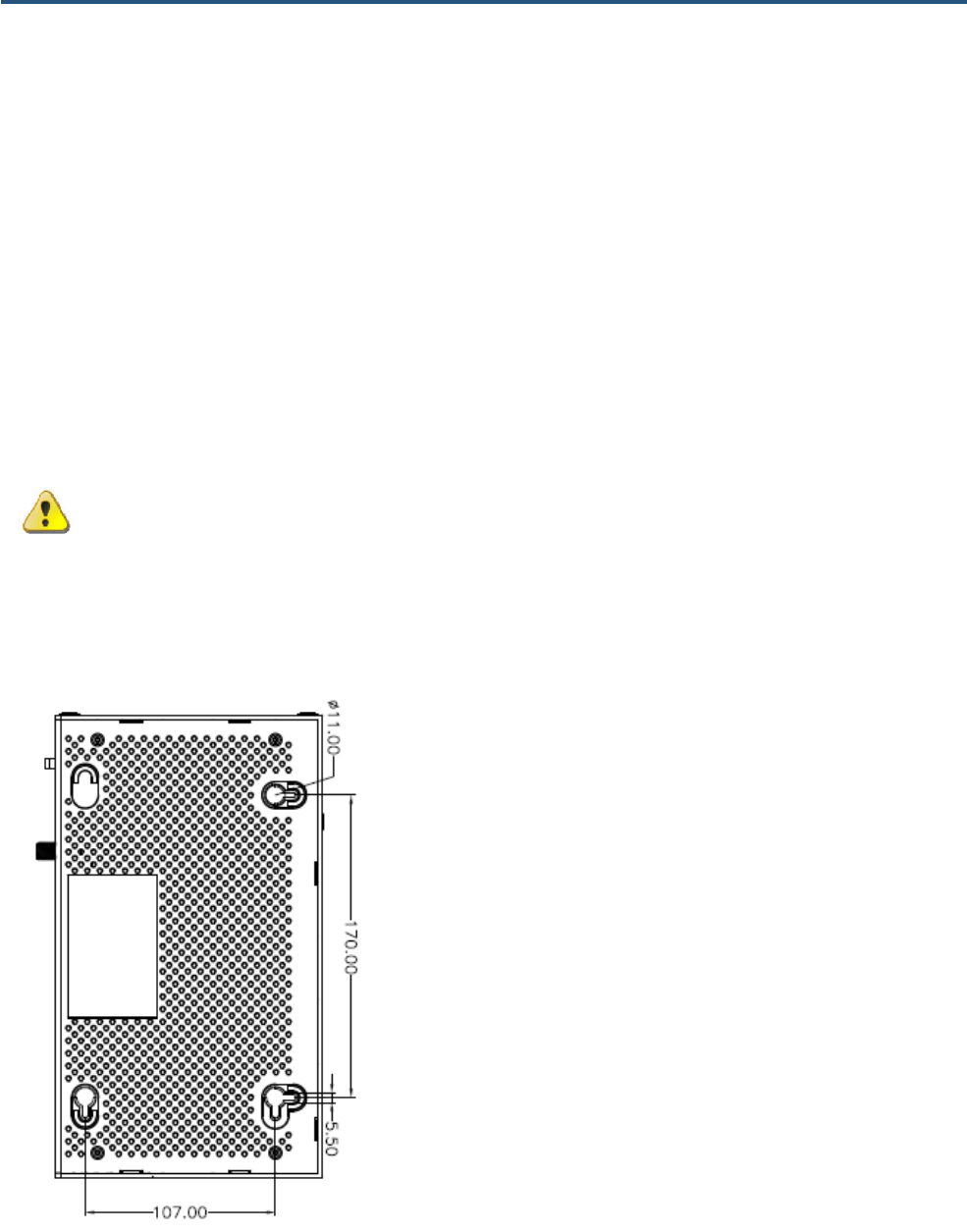
113
SMCD3GNV4 and SMCD3GNV4E Wireless EMTA Gateway Administrator Manual
Appendix A - Wall-Mounting the Gateway
The Gateway can be mounted on a wall. Wall mounting requires hanging the Gateway along its width or
length using the three slots on the bottom of the unit and the Gateway mounting template (on the next
page) for the screws.
WARNING: The Gateway should be wall mounted to concrete or plaster-wall-board. Before
drilling holes, check the structure for potential damage to water, gas, or electric lines.
To mount your Gateway on the wall:
1. Print the 1:1 wall-mounting template on the next page at 100% scale. Set page scaling to [None]
(100%). Do not reduce or enlarge the scale of the template.

114
SMCD3GNV4 and SMCD3GNV4E Wireless EMTA Gateway Administrator Manual
2. Measure the gap between holes with a ruler. Dimensionally confirm the template by measuring each
value for accuracy before drilling holes.
3. Use a center punch to mark the center of the holes.
4. Locate the marks on the wall for the mounting holes.
5. Drill holes to a depth and diameter appropriate for the size and type of hardware you have selected.
6. If necessary, install an anchor in each hole. Use M3.5 x 40 mm screws with a flat underside and
maximum screw head diameter of 6.5 mm (0.25 inches) to mount the Gateway.
7. Using a screwdriver, turn each screw until the head protrudes from the wall. The figure below is an
example for mounting Gateway on a concrete surface. Leave at least 2.5 mm (0.10 inches) between
the wall and the underside of the screw head. The maximum distance from the wall to the top of the
screw head is 5.0 mm (0.20 inches).
8. Place the Gateway so the keyholes are above the mounting screws.
9. Slide the Gateway down so it stops against the top of the keyhole opening.
10. Reconnect the coaxial cable and Ethernet cables. Reconnect the power cord to the Gateway and the
electrical outlet.

115
SMCD3GNV4 and SMCD3GNV4E Wireless EMTA Gateway Administrator Manual
Appendix B - Compliances
FCC Interference Statement
This equipment has been tested and found to comply with the limits for a Class B digital device pursuant
to Part 15 of the FCC Rules. These limits are designed to provide reasonable protection against radio
interference in a commercial environment. This equipment can generate, use and radiate radio
frequency energy and, if not installed and used in accordance with the instructions in this manual, may
cause harmful interference to radio communications. Operation of this equipment in a residential area is
likely to cause interference, in which case the user, at his own expense, will be required to take
whatever measures are necessary to correct the interference. If this equipment does cause harmful
interference to radio or television reception, which can be determined by turning the equipment off and
on, the user is encouraged to try to correct the interference by one of the following measures:
y Reorient or relocate the receiving antenna.
y Increase the separation between the equipment and receiver.
y Connect the equipment into an outlet on a circuit different from that to which the receiver is
connected.
y Consult the dealer or an experienced radio/TV technician for help.
The device complies with Part 15 of the FCC Rules. Operation is subject to the following two conditions:
(1) This device may not cause harmful interference, and (2) this device must accept any interference
received, including interference that may cause undesired operation.
FCC Caution: Any changes or modifications not expressly approved by the party responsible for
compliance could void the user’s authority to operate this equipment.
For product available in the USA/Canada market, only channel 1~11 can be operated. Selection of
other channels is not possible.
This device is can be operated in 5.15~5.25GHz frequency range, it is restricted in indoor environment
only.

116
SMCD3GNV4 and SMCD3GNV4E Wireless EMTA Gateway Administrator Manual
IMPORTANT NOTE:
FCC Radiation Exposure Statement
This equipment complies with FCC radiation exposure limits set forth for an uncontrolled environment.
This equipment should be installed and operated with minimum distance 20cm between the radiator &
your body.
This transmitter must not be co-located or operating in conjunction with any other antenna or
transmitter.
The availability of some specific channels and/or operational frequency bands are country dependent
and are firmware programmed at the factory to match the intended destination. The firmware setting is
not accessible by the end user.
Note to CATV System Installer - This reminder is provided to call the CATV systems installer's attention
to Section 820-40 of the National Electric Code (Section 54 of the Canadian Electrical Code, Part 1)
which provide guideline for proper grounding and, in particular, specify that the Coaxial cable shield
shall be connected to the grounding system of the building, as close to the point of cable entry as
practical.

117
SMCD3GNV4 and SMCD3GNV4E Wireless EMTA Gateway Administrator Manual
Index
2
2.4 GHz Wi-Fi network configuration settings, 36, 38
A
Adding blocked sites, 60
Adding computers, 57
Advanced page, 73
Application blocking, 65
At a glance page, 26
B
Blocked sites, 60
Blocking
applications and services, 65
devices, 67
keywords, 62
sites, 60
C
Changing login password, 101
CM Hardware page, 103
CM State page, 105
Computers, adding, 57
Computers, trusted, 63, 66, 68
Configuring
WPS, 41
Connected devices, 26
Connected Devices page, 55
Connecting
the WAN, 10
to the LAN, 9
Conventions, xii
D
Destination address, testing connection to, 99
Device blocking, 67
Device Discovery, 87
DHCP page, 108
Diagnostic tools, 98
Disable
port forwarding, 75
port triggering, 78
UPnP, 88
Wi-Fi, 35
WPS, 41
Disabling
blocked applications and services, 65
blocked devices, 67
blocked keywords, 62
blocked sites, 60
Disabling proxy settings, 17
DMZ, 84
Document
conventions, xii
organization, xi
E
Email notifications, 27
Enable
port forwarding, 75
port triggering, 78
UPnP, 88
Wi-Fi, 35

118
SMCD3GNV4 and SMCD3GNV4E Wireless EMTA Gateway Administrator Manual
WPS, 41
Enabling
blocked applications and services, 65
blocked devices, 67
blocked keywords, 62
blocked sites, 60
Ethernet port information, 49
Event Log page, 104
F
Factory defaults, restoring, 6, 100
Finding a suitable location, 8
G
Gateway
computers connected to, 56
connectivity to destination address, 99
key features, x
package contents, 2
powering on, 10
push-uttons, 4
rear panel, 5
rebooting, 6, 100
resetting, 6, 100
restoring factory defaults, 6, 100
suitable location, 8
system hardware information, 48
system requirements, 2
top panel, 3
USB devices connected to, 51
Gateway page, 25
GR909 test, 109
H
Home network connection status, 26
Home Network Wizard, 52
I
Installation
connecting the WAN, 10
connecting to the LAN, 9
finding a suitable location, 8
powering on the Gateway, 10
IPSec tunnels, 91
K
Key features, x
Keyword blocking, 62
L
LAN
connecting to, 9
LAN Ethernet port information, 49
Layer Two Tunneling Protocol, 89
Local IP network status, 29
Login password, changing, 101
Logs, 96
M
MTA page, 109
N
Network diagnostic tools, 98
Network updates, 26
P
Package contents, 2
Pair wireless client, 41
Parental Control page, 58
Parental control reports, 71
Password, changing, 101
PIN connection option, 41
Point-to-Point Tunneling Protocol, 89

119
SMCD3GNV4 and SMCD3GNV4E Wireless EMTA Gateway Administrator Manual
Port information, 49
Port triggering, 77
Powering on the Gateway, 10
Preparing to use the graphical user interface
disabling proxy settings, 17
Proxy settings, disabling, 17
Push-button connection option, 41
Push-buttons on Gateway, 4
Q
QoS, 85
R
Rear panel of Gateway, 5
Rebooting the Gateway, 6, 100
Recent network updates, 26
Remote management, 80
Reports, parental control, 71
Resetting the Gateway, 6, 100
Restoring
factory defaults, 6, 100
Wi-Fi defaults, 100
RF Parameters page, 106
Routing, 82
S
Safety instructions, iii
Services blocking, 65
Software version, 47
Software versions, 26
SSID network name
2.4 GHz, 36, 38
Status
local IP network, 29
WAN IP network, 29
WAN network, 43
Wi-Fi network, 29, 33, 35
Status page, 107
Suitable location, 8
System Config page, 112
System hardware information, 48
System logs, 96
System requirements, 2
System software version, 47
T
Telnet/SSH page, 111
Testing connection to
destination address, 99
Tools for network diagnostics, 98
Top panel of Gateway, 3
Troubleshooting
logs, 96
network diagnostic tools, 98
Troubleshooting page, 95
Trusted computers, 63, 66, 68
U
Unpacking, 2
Updates, 26
UPnP, enabling or disabling, 88
USB
hardware information, 51
V
Versions
software, 26
VPN global settings, 89
W
WAN
connecting, 10

120
SMCD3GNV4 and SMCD3GNV4E Wireless EMTA Gateway Administrator Manual
WAN IP network status, 29
WAN status, 43
Web management interface, 22
Advanced page, 73
Connected Devices page, 55
Gateway page, 25
IPSEC Tunnel page, 91
loggin in, 20
menus and submenus, 23
Parental Control page, 58
screens, 21
Troubleshooting page, 95
Web management interface pages
Add Blocked Keywords, 62
Add Blocked Service, 65
Add Blocked Sites, 60
Add Port Trigger, 78
Add Service, 75
At a Glance, 26
Change Password, 101
CM Hardware, 103
CM State, 105
Computers, 56
Device Discovery, 87
DHCP, 108
DMZ, 84
Edit Private WiFi Network (2.4 GHz), 36, 38
Email Notification, 27
Event Log, 104
Gateway Software Version, 47
Global Settings, 89
Home Network Wizard, 52
LAN Ethernet Hardware Info, 49
Local IP Network, 31
Logs, 96
Managed Devices, 67
Managed Services, 64
MTA, 109
Network Diagnostic Tools, 98
Port Triggering, 77
QoS, 85
Remote Management, 80
Reports, 71
RF Parameters, 106
Routing, 82
Status, 107
System Config, 112
System Hardware Info, 48
Telnet/SSH, 111
USB Hardware Info, 51
WAN, 43
WiFi, 33, 35
Wireless Hardware Info, 50
WPS, 41
Wi-Fi
2.4 GHz network, 36, 38
enable or disable, 35
Wi-Fi defaults, restoring, 100
Wi-Fi network status, 29, 33, 35
Wireless hardware information, 50
Wizard for home networks, 52
WPS configuration settings, 41
WPS connection
PIN, 41
push-button, 41

121
SMCD3GNV4 and SMCD3GNV4E Wireless EMTA Gateway Administrator Manual
20 Mason
Irvine, CA. 92618
U.S.A.
http://na.smc.com
Document number: 3124NCS03052012