SMC Networks RB5701 Fire/Alarm Central Panel User Manual uControl
SMC Networks Inc Fire/Alarm Central Panel uControl
UserManual.wiki
>
SMC Networks
>
RB5701 User Manual
>
User manual 1
Contents
1.
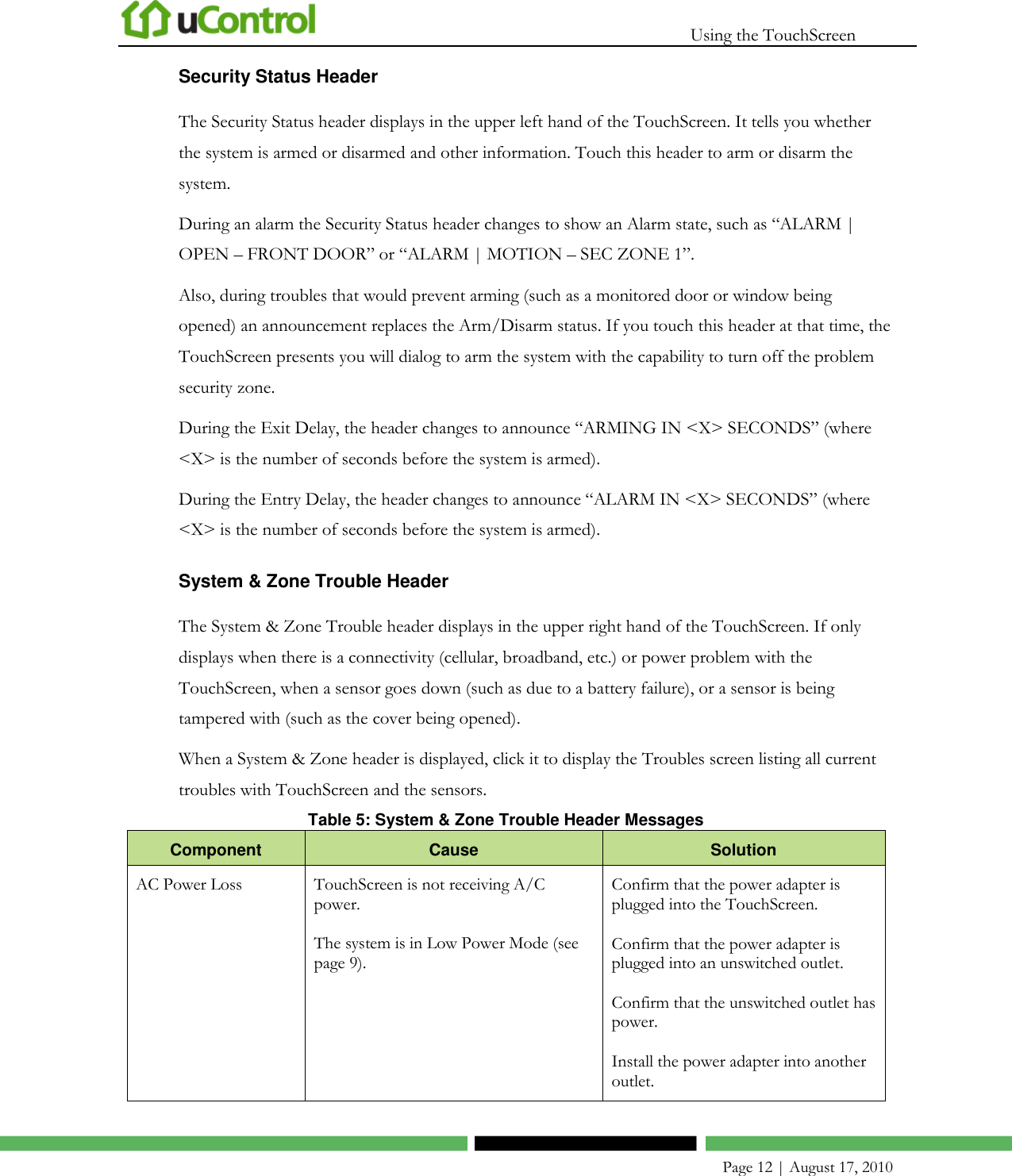
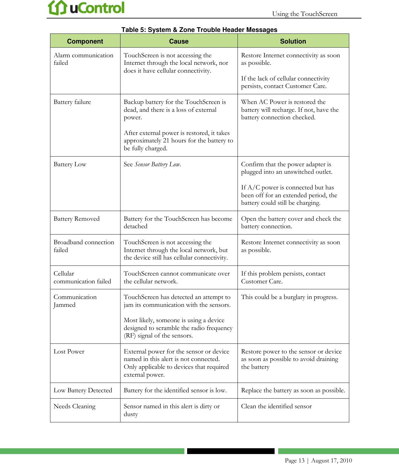
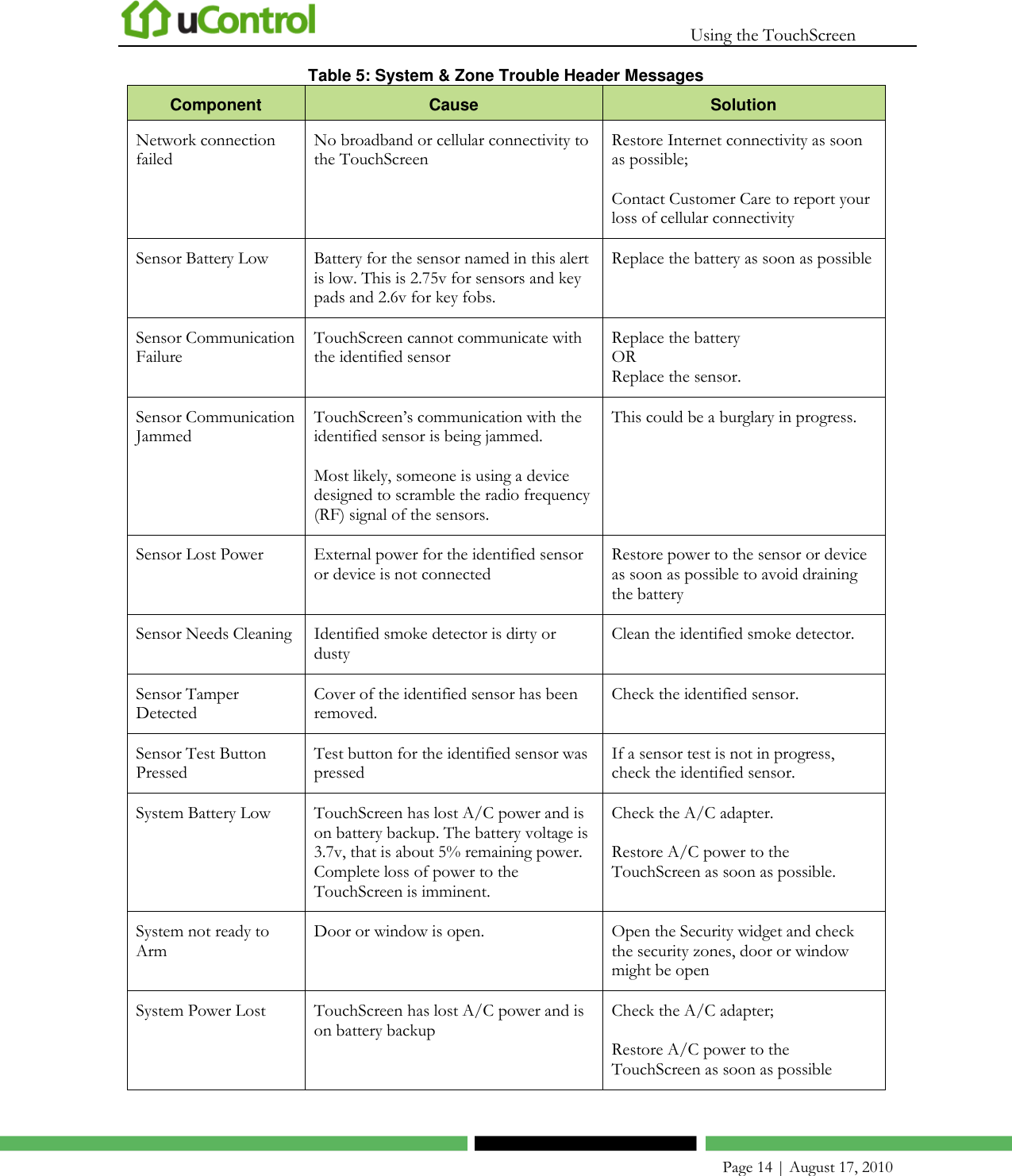
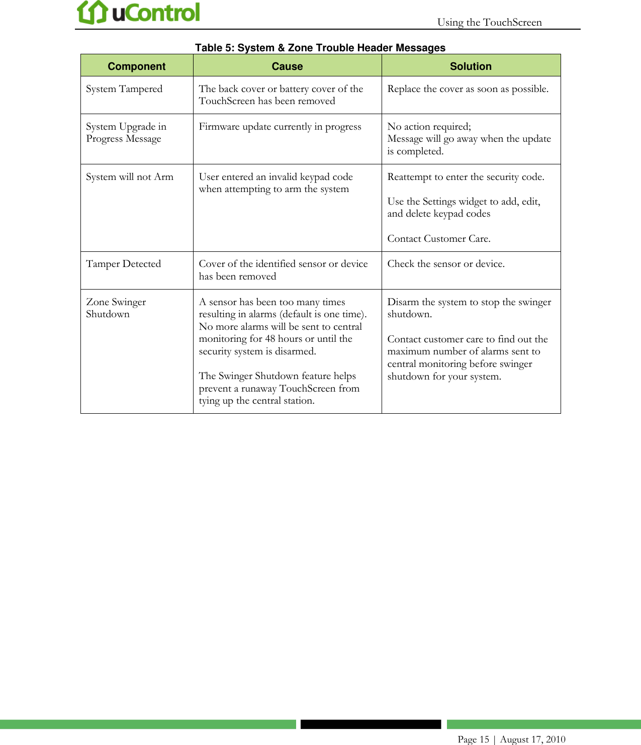
User manual 1
2.
User manual 2
User manual 1
Navigation menu
Upload a User Manual
Namespaces
Wiki Guide
HTML
PDF
Info
Views
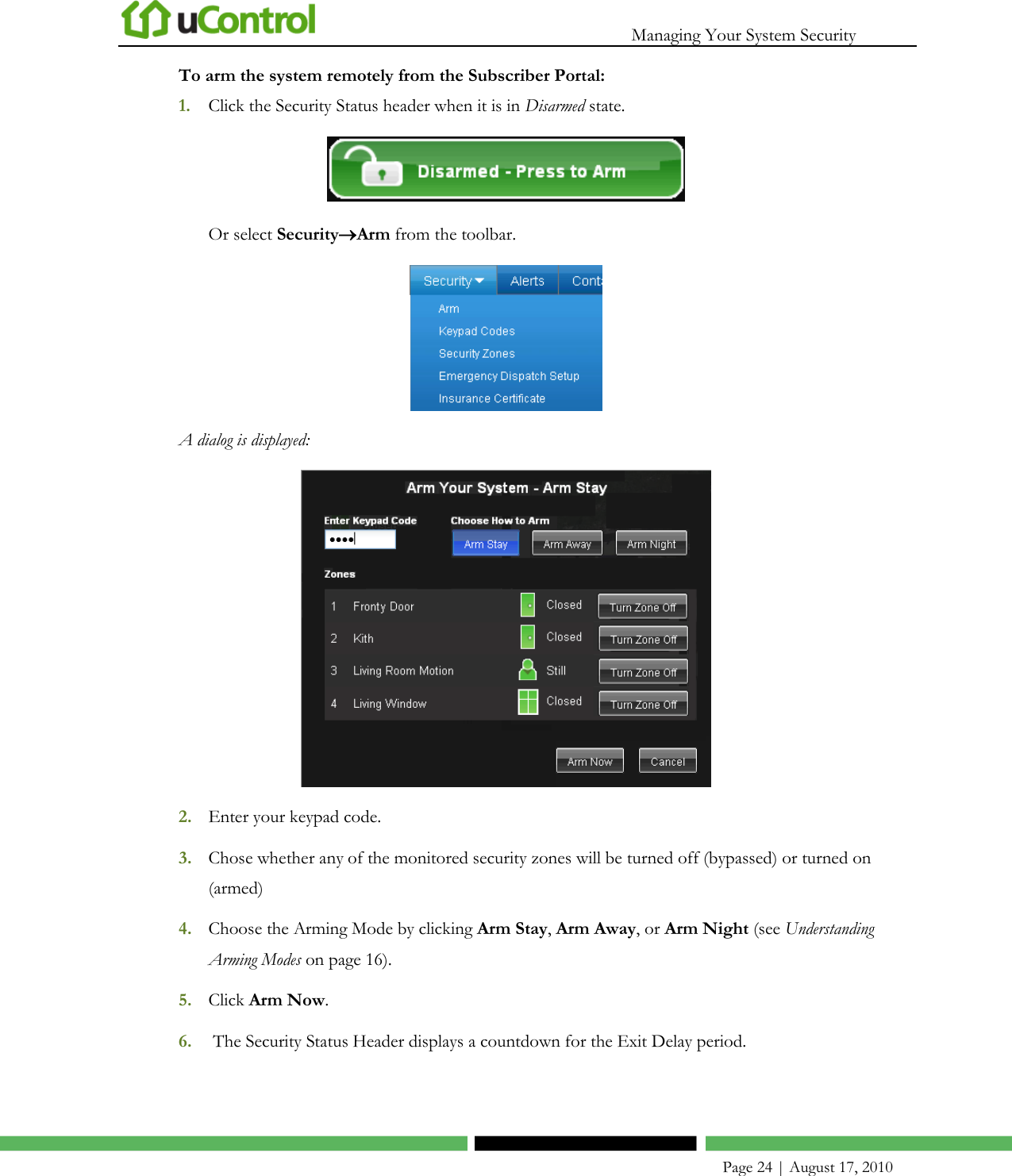
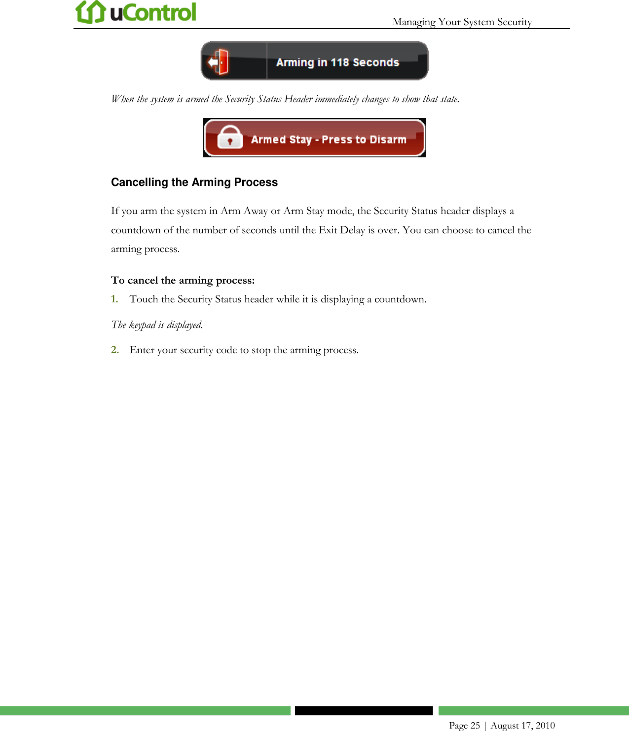
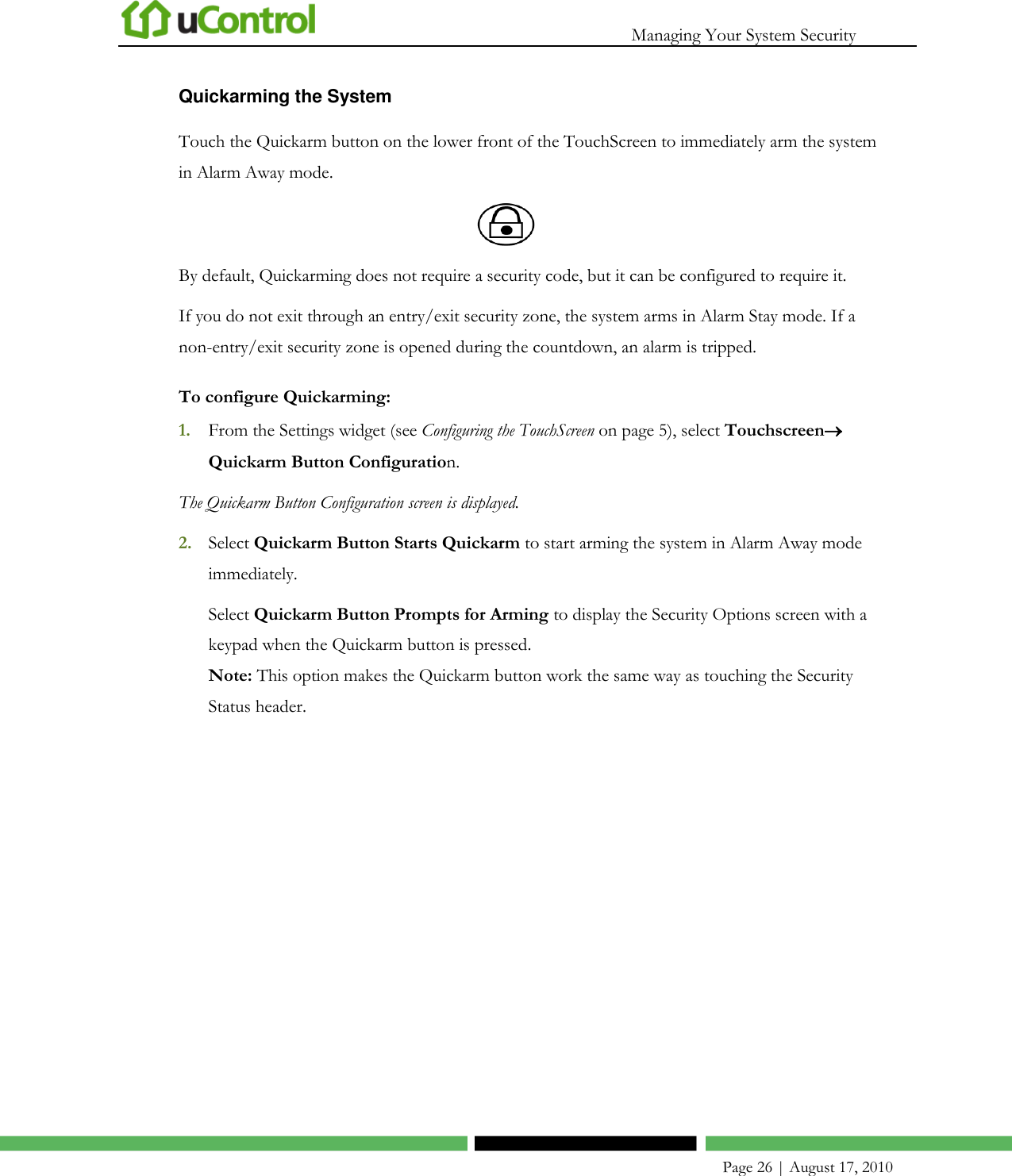
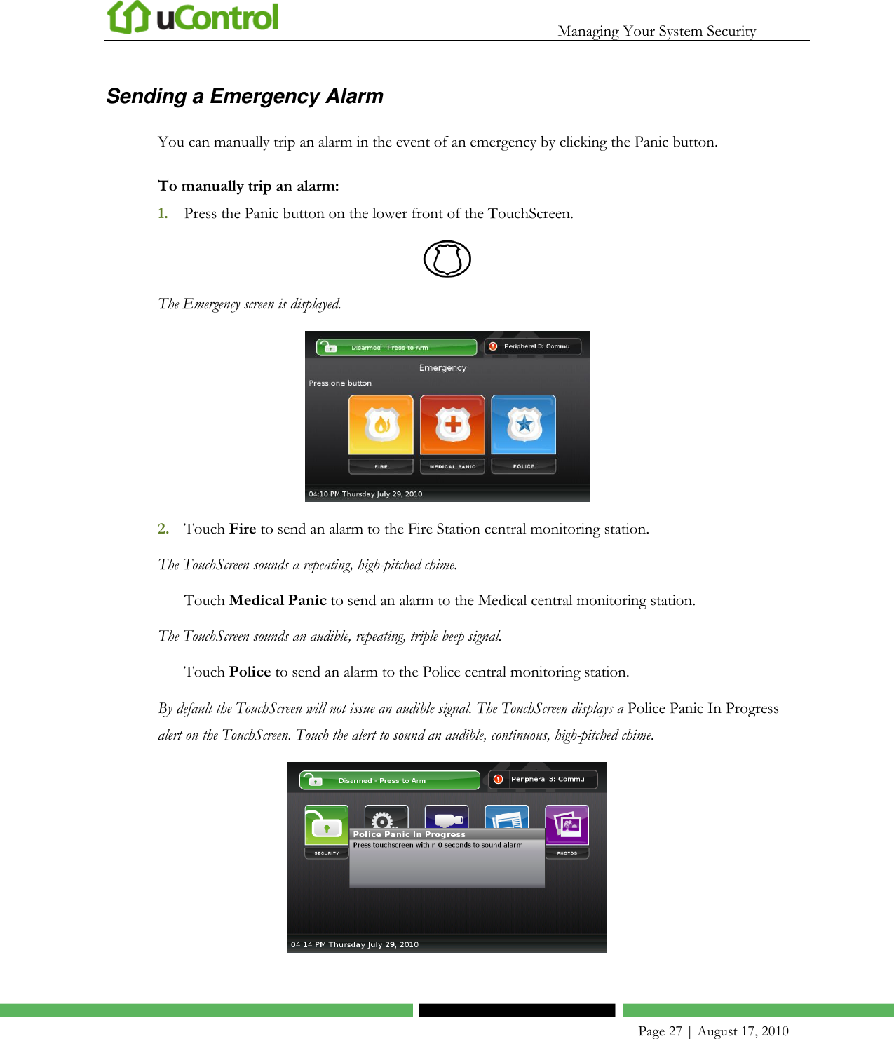
User Manual
Discussion / Help
Navigation