SMC Networks SMCDW01Z Zigbee RF Module User Manual
SMC Networks Inc Zigbee RF Module Users Manual
User manual
Copyright
©
2010 SMC Networks
Page 1
All Rights Reserved
I/M SMCDW01-Z rev. 1.0
8/24/10
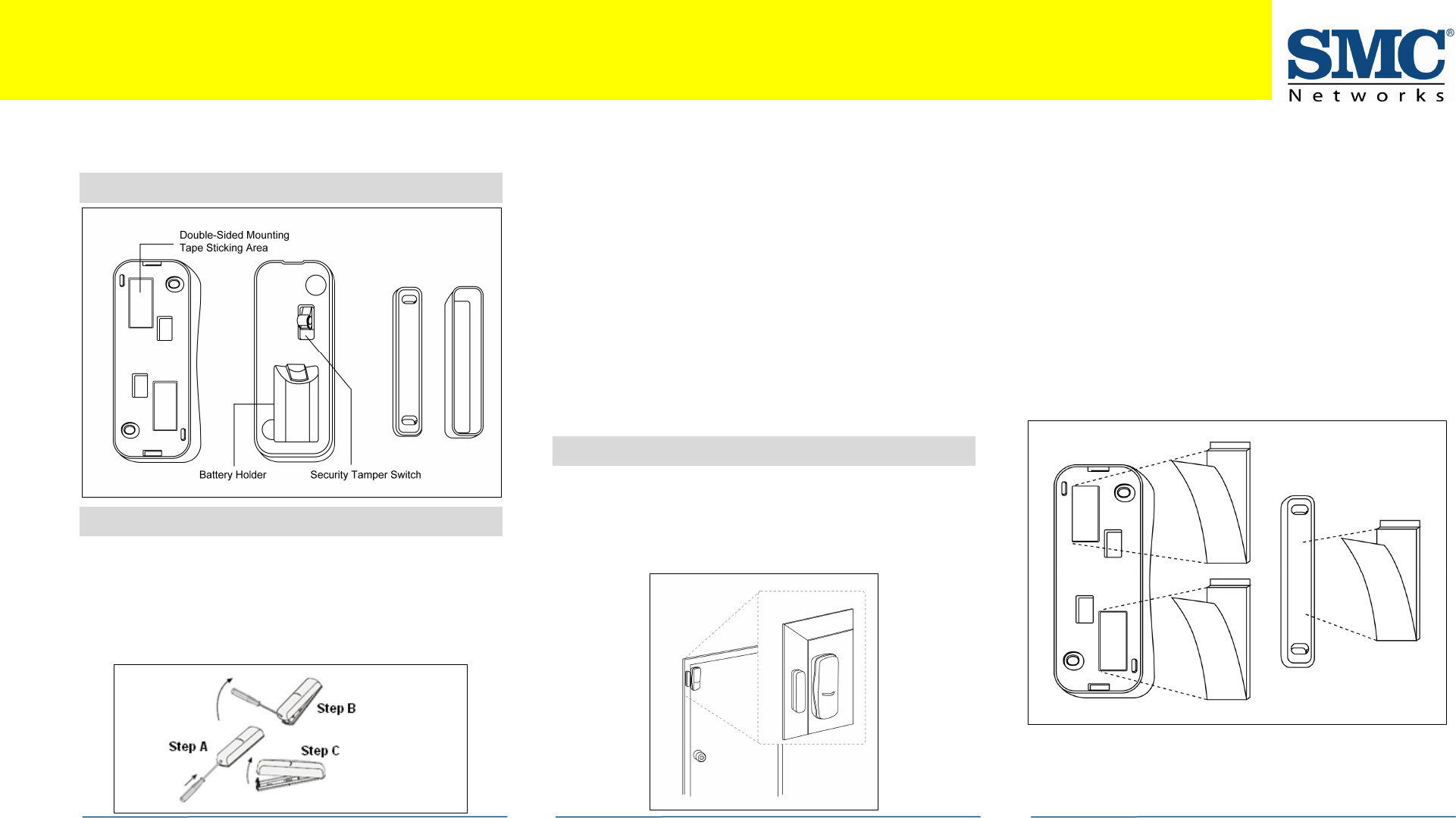
1
Key Components
2
Insert the Battery
A.
Find the locking mechanism on the bottom of the
SMCDW01-Z.
B.
Holding the SMCDW01-Z in one hand, carefully insert the
tip of a screwdriver into the locking mechanism.
C.
Push lightly upwards from the back of the SMCDW01-Z
until the back plate separates from the sensor.
D.
Find the supplied CR2 3-volt lithium battery.
E.
Find the tamper switch.
F.
While pressing and holding the tamper switch, insert the
battery into the SMCDW01-Z, with the positive (+) end
oriented towards the tamper switch. The front panel LED
goes ON.
G.
After 1 second, release the tamper switch. The LED
blinks green.
H.
Replace the SMCDW01-Z back plate.
I.
Align the magnet next to the SMCDW01-Z. The
SMCDW01-Z can now be added to the SMA Gateway.
Note: Do not physically mount the SMCDW01-Z until you
add it to the SMA.
3
Mounting the SMCDW01-Z
To mount the SMCDW01-Z to a wall, door, or window frame,
use double-sided mounting tape:
A.
Identify the locations on the SMCDW01-Z where double-
sided mounting tape can be applied.
B.
Wipe clean the surface where the SMCDW01-Z will be
mounted. Dust and particles can reduce the adhesion of
double-sided mounting tape you will use to mount the
SMCDW01-Z.
C.
Place the main sensor unit and magnet unit in such a
way that when the door or window is closed, the man
sensor unit and magnet unit are within 2cm. from each
other. When you open the door or window, these two
units should separate in proximity.
Note: For optimal radio communications, position the
SMCDW01-Z vertically against the door/window frame.
SMC
DW
01
-
Z
Door
-
Window
Sensor Quick Start Guide
continued on next page

SMCDW01-Z Door-Window Sensor Quick Start Guide
Copyright
©
2010 SMC Networks
Page 2
All Rights Reserved
I/M SMCDW01-Z rev. 1.0
8/24/10
D.
Do not mount the SMCDW01-Z directly on or near metal
framing or other large metallic objects, which can
weaken transmitted radio signal.
E.
Place the SMCDW01-Z indoors and away from sources of
water/moisture and other extreme weather conditions.
F.
Either screw the bidirectional mounting plate and
magnet unit into the wall, door or window frame. Use
the supplied screw anchors if attaching the SMCDW01-Z
to soft material, such as drywall.
AND/OR
Peel and attach the double-sided mounting tape to the
back of the bidirectional mounting plate and magnet
unit to adhere to the wall, door, or window frame.
4
Add the SMCDW01-Z to the SMA
A.
From the Home screen, touch the Settings widget.
A.
When the Keypad screen appears, touch the numbers to
enter your keypad code.
B.
When the Settings menu appears, use the keypad to
enter the Installer Code (this code is the same for all
SMA Gateways installed by your company).
C.
When the Technician keyboard pad appears, enter your
Technician ID and touch Done.
D.
When the Technician Settings menu appears, select
Sensors & Zones > Add a Sensor/Zone.
E.
When the Add a sensor screen appears, use the Arrow
buttons to select the number of sensors you want to add.
F.
Click Next. The Locating Sensors screen appears and the
system scans the premises for wireless sensors that can
be added, which must meet the following requirements:
-
Defaulted
-
Not currently paired with another SMA Gateway device
G.
Follow the system prompts to complete the add process.
Note: If no available sensors are found or fewer are found
than expected:
-
Touch Cancel Sensor/Zone Add to return to the
Technician Settings menu.
-
Touch Back to return to Add a Sensor screen.
H.
Check the signal strength between the SMCDW01-Z and
SMA Gateway (see “Test Signal Strength,” below.
I.
Mount the sensor to a door or window.
If you encounter a problem, see Step 7, “Troubleshooting.”
Note: The SMCDW01-Z uses one CR2, 3-volt lithium
battery. After you add it to the SMA system, it checks its
battery conditions automatically and reports the conditions
to the SMA Gateway. The SMA Gateway issues an alert if the
battery must be replaced.
5
Test Signal Strength
After adding the SMCDW01-Z to the SMA Gateway, test the
signal strength between the SMA Gateway and its added
sensors/security zones:
A.
Perform steps A through D in step 2, “Add the SMCDW01-
Z to the SMA.”
B.
When the Technician Settings menu appears, select
Sensors & Zones > Sensor Diagnostics.
C.
When the currently installed sensors/security zones
appear, touch the zone you want to test for connectivity
and follow the instructions from the SMA Gateway.
The Sensor Diagnostic for <Security Zone name> appears as
the system detects the current signal strength between the
selected sensor and the SMA Gateway.
6
4B
View Zone Event History
To view event history:
A.
Touch the Security widget on the Home screen.
B.
When the Dashboard appears, touch the History tab.
C.
The Zone Event History shows the event history.
continued on next
page
continued on next page
SMCDW01-Z Door-Window Sensor Quick Start Guide
Copyright
©
2010 SMC Networks
Page 3
All Rights Reserved
I/M SMCDW01-Z rev. 1.0
8/24/10
7
Disable Zones
The SMA system can bypass a zone, so the zone is not
monitored when the system is armed. This is useful when a
sensor is being repaired. You can only change the Bypass
state of a zone when the system is disarmed.
The system continues to log the activity of bypassed zones in
the Event History (see “View Zone Event History,” above).
To bypass a zone:
A.
With the system disarmed, touch the Security icon on
the Home screen.
B.
When the Dashboard screen appears, touch the Bypass
button for the zone to be bypassed. The Bypass button
of the zone changes to show it is bypassed.
When the system is disarmed, the Security Status header
notes that some of the zones have been bypassed.
8
Deleting a Sensor
Deleting a sensor from the premises removes it from being
monitored by the customer’s SMA system. This is not the
same as disabling (bypassing) a sensor. You should delete a
sensor only:
If the sensor is being de-installed from the SMA premises
To reset the sensor to factory default settings by
deleting the sensor and re-adding it immediately.
To delete a sensor from the SMA system:
A.
Perform steps A through D in step 2, “Add the SMCDW01-
Z to the SMA.”
B.
When the Technician Settings menu appears, select
Sensors & Zones > Delete a Sensor/Zone.
C.
When the Premise Passphrase keyboard appears, retrieve
the Premise Passphrase for the current SMA Gateway
(the Premise Passphrase is unique to the current SMA
Gateway and was generated upon Activation):
-
Login to the Management Portal via the Internet.
-
From the Dashboard, use the Start a Customer Search
tool to search for the current customer’s account.
-
When the Customer Search Results screen appears,
find the customer in the listed query results and click
the customer’s Account Number. The Account Details
of the current customer appears.
-
Find the section TouchScreen Premise Pass Phrase.
-
When the Premise Passphrase for the current SMA
Gateway appears, enter Premise Passphrase and click
Done. The currently installed sensors/security zones
appear.
D.
Touch the zone you want to delete and follow the
instructions provided by the SMA Gateway to delete the
sensor and security zone from the current SMA system.
9
5B
Troubleshooting
If you encounter a problem with the SMCDW01-Z:
Verify that a new battery has been properly installed
(see step 1, “Pre-installation Guidelines.”
Confirm that the SMCDW01-Z has been defaulted
Be sure the unlocated SMCDW01-Z is in working order if
only one multiple sensor failed.
Test signal strength between the sensor and SMA
Gateway (see Step 3, “Test the Signal Strength”).
Mount the SMCDW01-Z to a door or window.
Use the procedure in step 3 to check the signal strength
between the SMCDW01-Z and SMA Gateway again.
Compliances
FCC Notice: This device has been designed, constructed, and tested with
for compliance with FCC Rules that regulate intentional and unintentional
radiators. As the user of this device, you are not permitted to make any
alterations or modifications to this equipment or to use it in any way that is
inconsistent with the information described in this quick-start guide,
without the express written permission of SMC Networks. Doing so will void
your warranty to operate this equipment.
This device complies with Part 15 of the FCC rules. Operation of this device
is subject to the following two conditions:
1) This device may not cause harmful interference, and
2) This device must accept any interference received, including
interference that may cause undesired operation.
The SMCDW01-Z contains FCCID:JI5-SMCDW01Z and ICID:4137A-SMCDW01Z.
The “IC” designation preceding the radio certification number indicates
that this device complies with the Industry of Canada specifications.
ETL Notice: This device complies with all ETL and ETLC safety
requirements.
UL and ULC Notices: This device complies with UL Standard UL634 and ULC
Standard ULC C634.
Icons Meaning
/
Open/Closed doorway
/
Open/Closed window
Congratulations! You have successfully installed
the SMCDW01-Z Door-Window Sensor.