SMC Networks SMCZB01 Zigbee RF Module User Manual 1
SMC Networks Inc Zigbee RF Module 1
Contents
- 1. User manual 1
- 2. User manual 2
User manual 1
Copyright
©
2010 SMC Networks
Page 1
All Rights Reserved
I/M SMCMT01-Z rev. 1.0
8/25/10
1
0B
Verify Package Contents
SMC Networks provides the following items in your package:
1 SMCMT01-Z Motion Sensor with wireless radio installed
3 CR123A 3.0V lithium batteries
2 plastic masks
1 screw to secure the SMCMT01-Z to the wall-mounting
bracket
1 wall-mounting bracket
1 sheet of adhesive masking labels
1 cardboard undercrawl window mask
This Quick Start Guide
If an item is missing or damaged, contact your place of
purchase. The SMCT01-Z specifications are:
Power supply: 2.6 Volt to 3.6 Volt
Battery type: 3V Lithium, Duracell® 123, Sanyo® and
Panasonic®
CR123A
Life Expectancy: 3 years using 3 batteries
Current consumption walktest mode (LED flashing): 6 mA
Transceiver: ZigBee IEEE 802.15
Detection range: Up to 50 feet (15.2 m)
Mounting height: 6 to 10 feet (1.8 to 3 m)
Number of curtains: 9
Relative humidity: 10 to 85% non-condensing
Enclosure material: flame retardant ABS
2
1B
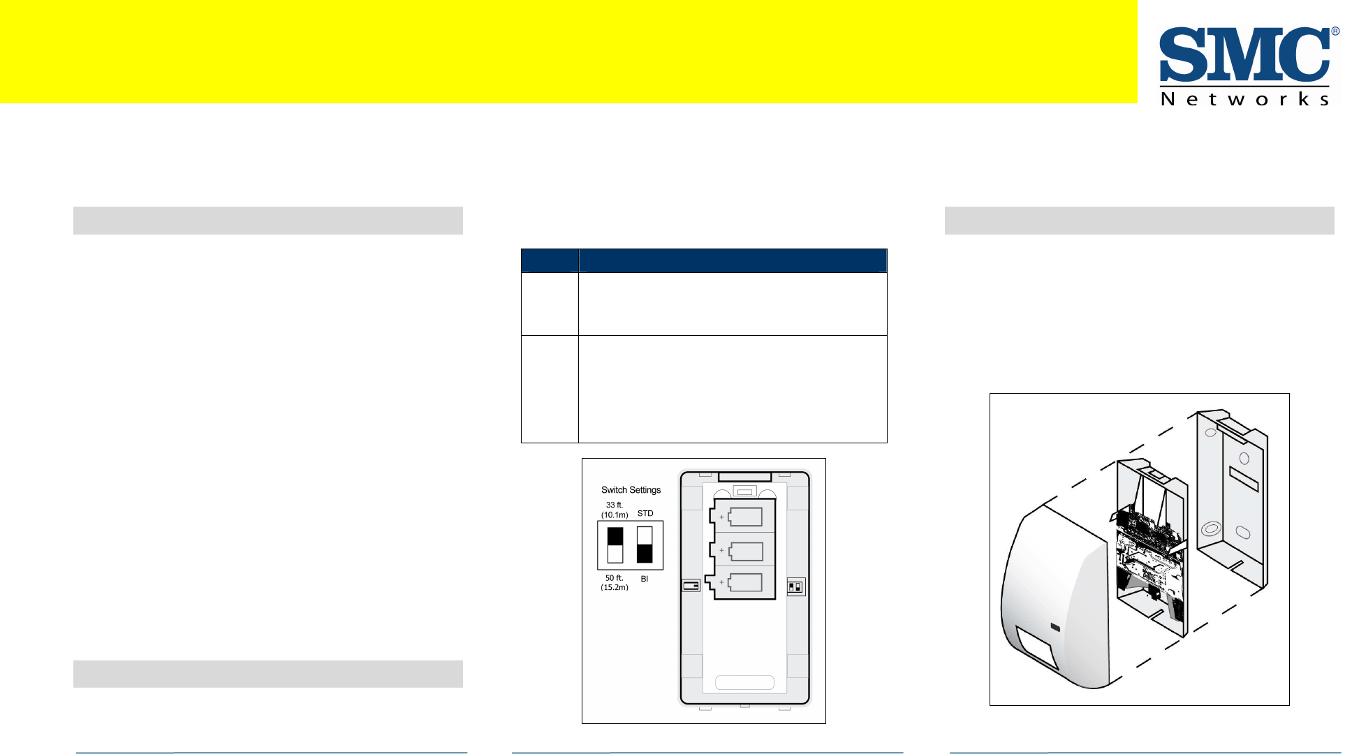
Set the Switches
The SMCMT01-Z Motion Sensor circuit board has 2 switches to
configure range and mode. To access the switches, use a flat
head screwdriver to press the back cover tabs to release the
back cover. Looking at the rear of the device, the switches
are to the right of the bottom battery holder.
3
Install Batteries
With the rear panel of the SMCMT01-Z removed, install three
3V Lithium batteries.
A.
Remove the back cover, if installed.
B.
Remove any old batteries and dispose of them properly.
C.
Place the 3.0V lithium batteries in the holder and press
each one into place.
D.
Leave the back cover off and go to the next section.
Switch Description
ON (down) = Detection range is 50 feet (15.2 m). RANGE
OFF (up) = Detection range is 33 feet (10.1 m). This is the
default.
ON (down) = Bi-curtain Mode. Increases false alarm
immunity in small areas. Intruders must pass through 2
curtains to trigger an alarm. Do not use for ranges under
5 feet (1.5 m). This is the default.
MODE
OFF (up) = Standard Mode. Use for wide-angle or single-
curtain applications. Intruders to only pass through 1
curtain to trigger an alarm.
Congratulations on purchasing your
SMCMT01
-
Z Motion Sensor
.
The SMCT01-Z Motion Sensor is a 35' passive infrared motion sensor with 80-pound pet immunity or a 50' standard sensor. It is highly sensitive to moving infrared sources
and features superior immunity to RFI, vibration, static electricity, temperature changes, and other false alarm sources. This Quick Start Guide has all the information to
get your SMCMT01-Z Motion Sensor up and running quickly. For detailed installation information, please see the SMCMT01-Z Motion Sensor User Manual.
SMCMT01
-
Z Motion Sensor Quick Start Guide
continued on next page
SMCMT01-Z Motion Sensor Quick Start Guide
Copyright
©
2010 SMC Networks
Page 2
All Rights Reserved
I/M SMCMT01-Z rev. 1.0
8/25/10
4
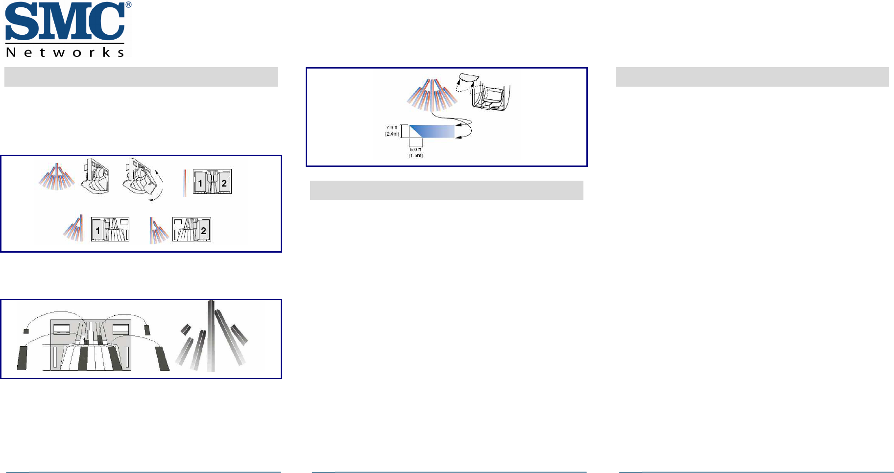
Select a Coverage Pattern
A.
If the SMCMT01-Z is closed, use a flat head screwdriver
to press the back cover tabs to release the back cover.
B.
If necessary, modify the coverage pattern as follows:
Plastic mask method: Use one or both supplied plastic
masks to mask off large areas of coverage.
Adhesive label method: Mask the appropriate mirror
curtains with the supplied adhesive labels. Do not use
sharp objects to remove unwanted labels, as the mirror
can get scratched. If necessary, peel off the label.
Cardboard mask method: Use the cardboard undercrawl
window mask. The undercrawl mask allows objects to be
placed within 5 feet (1.5 m) of, or directly below, the
SMCMT01-Z. If the mask will not be used, remove it.
5
Perform the Walk Test
To test the SMCTM01-Z operation and coverage pattern.
A.
If the SMCMT01-Z is closed, use a flat head screwdriver
to press the back cover tabs to release the back cover.
B.
Open the tamper switch to enable the Walk Test.
C.
Press the front cover release tab to remove the front
cover to access the Transmitter and PIR circuit boards.
D.
When the SMCMT01-Z is remounted on the bracket, the
Walk Test is enabled for 3-4 minutes. If more time is
required, press and release the tamper switch to reset
the Walk Test timer. Depending on switch settings (see
step 2), the Walk Test triggers an alarm when 1 or 2
curtain areas are entered and the LED on the front cover
goes ON to indicate an alarm.
E.
Walk test the detection pattern and make any necessary
adjustments.
F.
Replace and walk test the SMCMT01-Z to verify that it is
communicating with the control panel.
Note: When the test ends (3-4 minutes), the SMCMT01-Z
returns to normal mode, where it activates once every 3
minutes and the LED goes OFF to reduce battery drain.
6
Mount the SMCMT01-Z
Before touching the SMCMT01-Z, touch a grounded, bare
metal surface to remove static electricity or wear a
grounding strap.
A.
Mount the SMCMT01-Z from 7 to 10 feet (2.1 to 3.0 m)
high. For optimum detection and pet immunity, mount it
between 7 and 8 feet (2.1 and 2.4 m) high.
For pet alley applications, mount the SMCMT01-Z 3 feet
(0.9 m) above the floor, upside down, with the detector
window toward the ceiling. Use the standard mirror and
set the SENS jumper for increased sensitivity.
B.
Mount the SMCMT01-Z on a rigid vibration-free surface,
where it can detect the movements of an intruder.
C.
Avoid surfaces exposed to moisture and areas that can
expose the SMCMT01-Z to false alarm sources such as:
Direct sunlight
Heaters and radiators in the field of view
Strong air drafts (fans, air conditioners, etc.)
D.
Avoid areas where the ambient temperature is below
0° F (-18°C) or above 122°F (50°C).
E.
Do not aim the SMCMT01-Z at windows or glass doors.
To mount the SMCT01-Z:
A.
Touch a grounded, bare metal surface to remove static
electricity from your body or wear a grounding strap.
B.
Separate the PIR unit from the mounting bracket (see
the figure on the previous page).
continued on next page

Copyright
©
2010 SMC Networks
Page 3
All Rights Reserved
I/M SMCMT01-Z rev. 1.0
8/25/10
C.
Insert a small flat-head screwdriver between the tabs at
the bottom of the SMCMT01-Z and turn the screwdriver
to push the tabs apart.
D.
Select the appropriate knockout mounting holes on the
mounting bracket for corner or flat-wall mounting.
Note: Holes near the tamper actuator are not mounting
knockouts.
E.
Use screws and wall anchors, if necessary, to attach the
mounting bracket to the wall. Do not over tighten.
F.
Snap the SMCMT01-Z to the mounting bracket.
7
Pet Alley Application
To create a detection-free area close to the floor:
A.
Mount the SMCMT01-Z 3 feet (0.9 m) above the floor,
upside down with the detector window facing toward the
ceiling.
B.
Confirm that the undercrawl mask is in place to reduce
ceiling exposure. Coverage distance is 25 feet in Bi-
curtain Mode. Pets can roam freely below the SMCMT01-
Z mounting height, without triggering alarms.
C.
If you will not use the mask as described here or in step
4, remove the mask completely.
5
8
Battery Life Expectancy
Typical battery life expectancy for the SMCMT01-Z is 3 years
when using three batteries. The SMCMT01-Z uses two-way
wireless communication to extend battery life.
The following situations can reduce battery life:
If a receiver is unplugged or not installed.
Note: Transmitters continue to send supervision messages
until a receiver returns an acknowledgement.
After an hour, the transmitter only tries to send a
supervision message every 60 minutes.
Frequent transmissions, such as constant motion where
messages are sent every time the movement is detected.
To compensate for frequent motion, the SMCMT01-Z
automatically rests for three minutes after each
activation before any further motion can be detected.
When installed in extreme hot or cold environments.
The following situation can extend battery life:
Extend transmitter supervision time in panel
programming.
Infrequent transmission trips, such as a low traffic area
where messages are rarely sent.
9
Maintain the SMCMT01-Z
When installed and used properly, the SMCMT01-Z provides
years of service, with minimal maintenance. To ensure
proper operation:
Use the procedure in step 5 to walk test the SMCMT01-Z
at least once per year.
Clean the inside of the SMCMT01-Z with a soft-bristled
brush or compressed air.
Clean the cover with a water dampened cloth as needed
to keep it free of dust and dirt.
Always test the SMCMT01-Z after cleaning.
Congratulations! You have successfully installed the
SMCMT01-Z Motion Sensor.
SMCMT01
-
Z Motion Sensor Quick Start Guide

SMCMT01-Z Motion Sensor Quick Start Guide
Copyright
©
2010 SMC Networks
Page 4
All Rights Reserved
I/M SMCMT01-Z rev. 1.0
8/25/10
Compliances
FCC Notice
This device has been designed, constructed, and tested with
for compliance with FCC Rules that regulate intentional and
unintentional radiators. As the user of this device, you are
not permitted to make any alterations or modifications to
this equipment or to use it in any way that is inconsistent
with the information described in this quick-start guide,
without the express written permission of SMC Networks.
Doing so will void your warranty to operate this equipment.
This device complies with Part 15 of the FCC rules.
Operation of this device is subject to the following two
conditions:
1) This device may not cause harmful interference, and
2) This device must accept any interference received,
including interference that may cause undesired operation.
The SMCMT01-Z contains FCCID:JI5-SMCZB01 and ICID:4137A-
SMCZB01. The “IC” designation preceding the radio
certification number indicates that this device complies with
the Industry of Canada specifications.
ETL Notice
This device complies with all ETL and ETLC safety
requirements.
UL and ULC Notices
This device complies with UL Standard UL639 and ULC
Standard ULC S306.
Limitations of Security Products
Security products and alarm systems do not offer guaranteed
protection against burglary, fire, or other emergencies. They
may fail to warn for diverse reasons, including (but not
limited to): power failure, dead batteries, improper
installation, coverage , coverage areas overlooked during
installation, defeat by technically sophisticated intruders,
component failure, or inadequate maintenance. Alarm
systems should be checked weekly to ensure that all devices
are working properly.
AN ALARM SYSTEM IS NOT A SUBSTITUTE FOR INSURANCE.