SMC Networks SMCZB01 Zigbee RF Module User Manual 2
SMC Networks Inc Zigbee RF Module 2
Contents
- 1. User manual 1
- 2. User manual 2
User manual 2

Copyright
©
2010 SMC Networks
Page 1
All Rights Reserved
I/M SMCSM01-Z rev. 1.0
8/19/10
1
Unpacking
Your SMCSM01-Z package includes the following items:
One SMCSM01-Z Smoke Sensor
One dust cover
Two CR123A batteries
Mounting bracket
This user manual
If any items are missing or damaged, contact your place of
purchase. Keep the carton, including the original packing
material, in case you need to store or return the product.
2
Specifications
The SMCSM01-Z specifications are:
Voltage: 3VDC
Battery type1 3V Lithium, Duracell
®
123, Sanyo
®
, and
Panasonic
®
CR123A
Sensitivity 2.25 % ± 1.35 %
Drift compensation adjustment 0.5%/ft. max
Operating temperature: 40° to 100° F (4.4° and 37.8° C)
Compatible control panel: RB5701-Z SMA Gateway
The SMCSM01-Z specifications heat alarm specifications are:
Rate-of-rise: 15°F/min >105°F (8.3°C/min > 40.6°C)
Fixed: 135°F ± 5°F (57.2°C ± 2.8°C)
Note: Constant exposures to high or low temperatures or
high humidity may reduce battery life.
3
NFPA Guidelines
NFPA 72, 2-1.4.2.1 Total (Complete) Coverage
If required, total coverage shall include all rooms, halls,
storage areas, basements, attics, lofts, spaces above
suspended ceilings, and other subdivisions and accessible
spaces; and the inside of all closets, elevator shafts, enclosed
stairways, dumbwaiter shafts, and chutes. Inaccessible areas
shall not be required to be protected by detectors. (For
exceptions, refer to NFPA 72.)
NFPA 72, 2-1.4.2.2 Partial Coverage
If required, partial detection systems shall be provided in all
common areas and work spaces, such as corridors, lobbies,
storage rooms, equipment rooms, and other tenantless spaces
in those environments suitable for proper detector operation in
accordance with this code.
NFPA 72, 2-1.4.2.3 Selective Coverage
Where codes, standards, laws, or authorities having
jurisdiction require the protection of selected areas only, the
specified areas shall be protected in accordance with this
code.
NFPA 72, 2-1.4.2.4 Supplementary (Non required)
Coverage
Where installed, detection that is not required by an
applicable law, code, or standard, whether total (complete),
partial, or selective coverage, shall conform to the
requirements of this code. (For exceptions, refer to NFPA 72
Chapter 2 Spacing Requirements.)
NFPA 72, 2-1.4.3
Where non required detection devices are installed for a
specific hazard, additional non required detection devices shall
not be required to be installed throughout an entire room or
building.
NFPA 72, 2-2 Heat-Sensing Fire Detectors
Heat-sensing fire detectors shall be installed in all areas where
required by the NFPA codes and standards or by the authority
having jurisdiction.
NFPA 72, 8-1.4.1.3.2 Detection in New Apartment
Buildings
Approved, single-station smoke alarms shall be installed in
accordance with 7-6.2.10 of NFPA 101 outside every sleeping
area in the immediate vicinity of the bedrooms and on all
levels of the dwelling unit including basements. (101: 18-
3.4.4.2) (For exceptions, refer to this section of NFPA 72.)
NFPA 72, 8-1.4.1.4.2 Detection in Existing Apartment
Buildings Approved, single-station smoke alarms shall be
in-stalled in accordance with 7-6.2.10 of NFPA 101
outside every sleeping area in the immediate vicinity of
the bedrooms and on all levels of the dwelling unit
including basements. (101: 19-3.4.4.1) (For exceptions,
refer to this section of NFPA 72.)
4
Technical Bulletin
SMCSM01-Z is a member of SMC Networks’ family of reliable,
high-quality products using the latest technology available.
Please review the information in this section to ensure you
get the most out of your new SMCSM01-Z Smoke Sensor.
Pre-installation Considerations
Install the SMCSM01-Z in accordance with the National Fire
Protection Association’s (NFPA) Standard 72, Chapters 2 and
8. Depending on the application, you may need to reference
other chapters of NFPA 72 or NFPA 101.
SMC
SM
01
-
Z
S
m
oke
Sensor
User Manual
Congratulations on purchasing your
SMC
SM
01
-
Z
Smoke
Sensor
.
The SMCSM01-Z Smoke Sensor is a
low-profile wireless smoke detector designed to provide reliable smoke or fire detection. The SMCSM01-Z is ideal for difficult-to-wire
residential or commercial applications. This user manual has all the information to get your SMCSM01-Z Smoke Sensor up and running quickly.
continued on next page

SMCSM01-Z Smoke Sensor Quick Start Guide
Copyright
©
2010 SMC Networks
Page 2
All Rights Reserved
I/M SMCSM01-Z rev. 1.0
8/19/10
Placing the SMCSM01-Z
When choosing a location to install the SMCSM01-Z, consider:
Use of structure and type of construction
Contents you want to protect and their burning
characteristics
Human occupancy
Total area to be monitored
Ceiling height and surface condition
Air movement and vent locations
Obstructions
Deflections
After considering these factors, choose a location:
Where the temperature range is between 40° and 100° F
(4.4° and 37.8° C).
Where the humidity is between 0 and 90%
noncondensing.
Away from ventilation sources that can prevent smoke
from reaching the SMCSM01-Z.
That is at least 5 feet (1.5 m) from bathrooms.
When placing the SMCSM01-Z on a ceiling, mount it in the
center of the room or hallway, at least 4 inches (10cm) away
from any walls or partitions.
When mounting the SMCSM01-Z on a wall, place it so the top
is 4 to 12 inches (10 to 31cm) below the ceiling.
In rooms with sloped, peaked, or gabled ceilings, locate
SMCSM01-Z sensors 3 feet (.9 m) down or away from the
highest point of the ceiling.
If mounting to suspended ceiling tile, secure the tile with
the appropriate fastener to prevent tile removal.
Locations to Avoid
Areas where normal ambient temperature exceeds 100°
F (37.8° C).
Dirty, dusty, insect infested areas.
In or near areas with combustion particles (kitchens, gar-
ages, furnaces, hot-water heaters, gas space heaters).
On the ceiling in rooms next to kitchens, where there is
no transom between the kitchen and such rooms.
Damp or humid areas, or near bathrooms with showers.
Near fresh-air inlets or returns or very drafty areas.
Near heating/air conditioning vents, fans, and fresh air
intakes, which can drive smoke away from the sensor.
In dead-air spaces at the top of peaked ceilings or in
corners where walls and ceiling meet. Dead air can
prevent smoke from reaching a smoke alarm/detector.
Within 10 feet (3 m) of fluorescent light fixtures.
4B
Installing the SMCSM01-Z
A.
Slide the battery compartment cover away from the
SMCSM01-Z to unsnap it and lift it off.
B.
Observing proper polarity, insert two 3V lithium
batteries into the SMCSM01-Z battery compartment and
replace the battery compartment cover.
C.
Remove the red plastic dust cover from the SMCSM01-Z.
The sensor ships with a dust cover for protection on
construction sites with dusty environments.
D.
Disconnect alarm-notification appliances, service-release
devices and extinguishing systems. Test communications
between the control panel and the SMCSM01-Z before
permanently mounting the sensor as follows:
-
Hold the SMCSM01-Z where you plan to install it.
-
Press the SMCSM01-Z test button for 8-to-10 seconds.
The SMCSM01-Z sends a signal to the control panel.
-
At the control panel, verify the signal was received
and that RF signal strength is adequate. If no signal is
received or the RF signal is low, relocate the
SMCSM01-Z and retest.
E.
Using two supplied screws and anchors, mount the base.
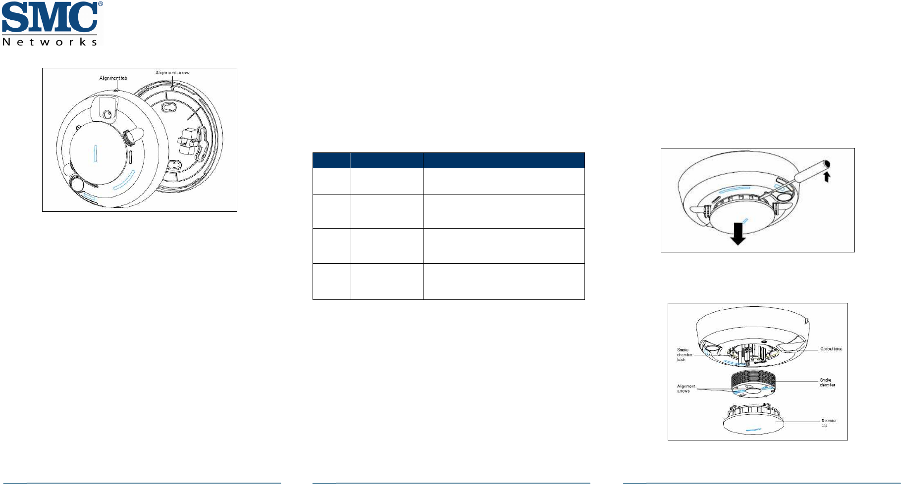
F.
Attach the SMCSM01-Z to the mounting base as follows:
-
Line up the raised alignment tab on the lip of the
SMCSM01-Z with the arrow on the mounting base.
-
Insert the SMCSM01-Z into the base and turn clockwise
about 15 degrees until it snaps into place.
Note: The SMCSM01-Z cannot be attached to the mounting
base if no batteries are installed.
continued on next page
SMCSM01-Z Smoke Sensor Quick Start Guide
Copyright
©
2010 SMC Networks
Page 3
All Rights Reserved
I/M SMCSM01-Z rev. 1.0
8/19/10
G.
Test communications between the control panel and
SMCMS01-Z again:
-
Press the Test button on the alarm for 8-to-10
seconds. The SMCMS01-Z sends a signal to the control
panel.
-
Verify that the signal at the control panel was
received.
H.
Test the SMCMS01-Z (see “Sensitivity Testing” on this
page).
Note: The control panel alarm and all auxiliary functions
should be verified for a complete test of the system.
Sensitivity Testing
A.
Press the SMCMS01-Z Test button for 4 seconds. When
the test starts, the SMCMS01-Z LED flashes 1 to 9 times.
B.
Count the number of LED flashes and see the table
below to determine the status of the SMCMS01-Z
sensitivity and any action to take.
Understanding the LED
The LED on the SMCSM01-Z shows the following status:
Flash = normal operation
ON = smoke detected, sending an alarm
OFF = trouble or maintenance is required
Annual Testing
Test the SMCMS01-Z in place annually using Smoke! in a can®
(product number SM-200), a canned aerosol simulated smoke
and follow the directions on the can.
Cleaning the SMCSM01-Z
Clean the SMCSM01-Z cover with a dry or damp (water) cloth
as needed to keep it free from dust and dirt. When
necessary, use the following procedure to clean the interior
of the SMCSM01-Z and replace the smoke chamber.
A.
Notify the Central Monitoring Station that the smoke
sensor is being tested. Make sure the system is in Test
mode with the Central Monitoring Station.
B.
Remove the SMCSM01-Z from its mounting base (see
“Mounting Base Instructions” on page 4).
C.
Remove batteries (see “Replacing Batteries” on page 4).
D.
Slide a flat-blade screwdriver in the detector cap slot.
Gently push the handle down to pry the cap up and off.
E.
Squeeze the smoke chamber where indicated by the
alignment arrows and pull it up and away from the
SMCSM01-Z and discard. See the following figure.
F.
Blow out or use a soft-bristled brush to remove dust and
dirt from the smoke chamber base.
Flashes Meaning Steps to Take
1 Unserviceable
hardware fault
Reset the SMCMS01-Z and rerun sensitivity
test. If error persists, replace the sensor.
2 – 3 SMCMS01-Z is
becoming
insensitive
Clean the SMCMS01-Z, reset it, and rerun
the sensitivity test. If the error persists,
replace the sensor.
4 – 7 SMCMS01-Z is
within normal
sensitivity range.
None
8 - 9 SMCMS01-Z is
becoming too
sensitive.
Verify that the smoke chamber is snapped
down securely. Clean the SMCSM01-Z and
replace the smoke chamber.
continued on next page
SMCSM01-Z Smoke Sensor Quick Start Guide
Copyright
©
2010 SMC Networks
Page 4
All Rights Reserved
I/M SMCSM01-Z rev. 1.0
8/19/10
G.
Line up the new smoke chamber with the optical base by
aligning the arrows on the smoke chamber to the latches
on the optical base and snap down into place.
H.
Replace the detector cap by lining up the cap with the
SMCSM01-Z. Then insert the cap into the SMCSM01-Z and
turn clockwise approximately 15 degrees. The cap snaps
firmly into place when secure.
I.
Insert the batteries into the SMCSM01-Z using the proper
polarity, and replace the battery compartment cover.
J.
Reattach the SMCSM01-Z to its mounting base (see
“Mounting Base Instructions” on this page.
K.
Test the SMCSM01-Z sensitivity and contact the Central
Monitoring Station to place the system back online
(remove from Test mode).
Note: Verify all auxiliary functions for a complete test of
the system.
Maintaining the SMCSM01-Z
The SMCSM01-Z requires minimal maintenance for easy field
service and maintenance.
A.
Test the SMCSM01-Z weekly (see “Sensitivity Testing” on
page 3). If it requires maintenance, the LED goes OFF
and a signal is sent to the control panel as described in
the following table.
Note: The SMCSM01-Z does not provide warnings for fires
resulting from explosions, smoking in bed, or other
furniture, ignition of flammable liquids, vapors and gases,
children playing with matches or lighters.
Replacing Batteries
Use only 3V lithium 123 batteries, as listed on the battery
compartment cover.
A.
Remove the SMCSM01-Z from the mounting base (see
“Mounting Base Instructions” on this page).
B.
Slide the battery compartment cover away from the
SMCSM01-Z to unsnap it and lift it off (see the figure on
page 2).
C.
Remove and dispose of the batteries appropriately.
D.
Observe correct polarity and insert two new 3V lithium
batteries into the battery compartment and replace the
cover.
Note: Use only new batteries when replacing old batteries.
Do not replace with batteries that were used previously.
E.
Reattach the SMCSM01-Z to the mounting base and test
the system.
Mounting Base Instructions
To remove the SMCSM01-Z from the mounting base:
A.
Hold the SMCSM01-Z.
B.
Turn it counterclockwise approximately 15 degrees. The
SMCSM01-Z snaps off from the mounting base.
To attach the SMCSM01-Z to the mounting base:
A.
Line up the raised alignment tab on the lip of the
SMCSM01-Z with the arrow on the mounting base (see
the figure on page 2).
B.
Insert the SMCSM01-Z into the base and turn clockwise
approximately 15 degrees. It snaps firmly into place
when secure.
Compliances
The information in this guide is in accordance with NFPA 72 and/or CAN/ULC-
S524, depending on country of installation.
FCC Notice
This device has been designed, constructed, and tested with for compliance with FCC
Rules that regulate intentional and unintentional radiators. As the user of this device,
you are not permitted to make any alterations or modifications to this equipment or to
use it in any way that is inconsistent with the information described in this quick-start
guide, without the express written permission of SMC Networks. Doing so will void
your warranty to operate this equipment. This device complies with Part 15 of the
FCC rules. Operation of this device is subject to the following two conditions:
1) This device may not cause harmful interference, and
2) This device must accept any interference received, including
interference that may cause undesired operation.
The SMCSM01-Z contains FCCID:JI5-SMCZB01 and ICID:4137A-SMCZB01. The
“IC” designation preceding the radio certification number indicates that this
device complies with the Industry of Canada specifications.
ETL Notice: This device complies with all ETL and ETLC safety
requirements.
UL and ULC Notices: This device complies with UL Standard UL268 and ULC
Standard ULC S529.
Smoke detectors are not to be used with detector guards, unless the
combination has been evaluated and found suitable for that purpose.
Signal Meaning
CleanMe SMCSM01-Z sensitivity is out of range and needs cleaning.
See “Cleaning the SMCSM01-Z” on page 3.
Maintenance
alert
SMCSM01-Z failed power-up self test. Perform a sensitivity
test (see “Sensitivity Testing” on page 3). If the problem
persists, replace the SMCSM01-Z.
Low battery Batteries are low and must be replaced as soon as possible.
Congratulations! You have successfully installed
the SMCSM01-Z Smoke Sensor.