SNAPPER Walk Behind Lawnmower, Gas Manual L0808100
User Manual: SNAPPER SNAPPER Walk Behind Lawnmower, Gas Manual SNAPPER Walk Behind Lawnmower, Gas Owner's Manual, SNAPPER Walk Behind Lawnmower, Gas installation guides
Open the PDF directly: View PDF ![]() .
.
Page Count: 47

OPERATOR'S
MANUAL
SW20Series
Walk-BehindMowers
Model Humber:
5900700
5900702
Description
SW20KAV1748, 17HP Kawasaki, 48" Cut Walk-Behind Mower
SW20KAV133B, 13HP Kawasaki, 36" Cut Walk-Behind Mower
Briggs &Stratton Power ProductsGroup
5375 North Main Street
Munnsville, NY 13409
800-933-6175
5101263
RevisionIR
Rev.Date:11/2007
TP 100-7359-1R-WD-SP
Thankyoufor purchasingthis quality-built SnapperPro product. We're pleasedthat
you've placedyour confidencein the SnapperPro brand. When operatedand maintained
accordingto the instructions in this manual,your SnapperPro product will provide many
yearsof dependableservice.
This manual containssafety informationto makeyou awareof the hazardsand
risks associatedwith this machineand how to avoid them. This machineis designedand
intendedto be usedand maintainedaccordingto the manualand operatedby trained
professionalsfor finish cutting of establishedlawnsand is not intendedfor any other
purpose. It is importantthat you readand understandthese instructions thoroughly
beforeattemptingto start or operatethis equipment
Unit Model Number
Mower Deck ModelNumber
DealerName
Unit SERIALNumber
Mower DeckSERIALNumber
DatePurchased
EngineMake EngineModel
EngineType/Spec EngineCode/SerialNumber
SeeFeatures and Controls for the location of Identification Numbers
DATEPURCHASED
Briggs & Stratton Power Products Group
Copyright {©2008 Briggs & Stratton Corporation
Milwaukee, WI, USA. All rights reserved.
The Snapper Pro logo is atrademark of Briggs & Stratton
Corporation Milwaukee,WI, USA.
Contact Information:
Briggs & Stratton Power Products Group
5375 N. Main St.
Munnsville, NY 13409-4003
(800) 933-6175
www.SnapperPro.com
,AI WARNING
The engineexhaustfrom this product contains chemicals
known to the State of California to cause cancer, birth
defects, or other reproductive harm.

Table of Contents
Operator Safety ..................................................... 2
Safety Rulesand Information...........................................2
Safety Decals....................................................................8
Safety InterlockSystem....................................................9
Features & Controls.............................................. 10
IdentificationNumbers ...................................................10
Control Functions...........................................................11
Operation ........................................................... 13
General...........................................................................13
Checks Before Starting.................................................. 13
Checking Tire Pressures.................................................14
Pushing the Unit by Hand...............................................14
Cutting HeightAdjustment..............................................15
Starting the Engine.........................................................17
Stopping the Mower .......................................................17
Driving the Mower..........................................................18
Mowing...........................................................................20
Mowing Recommendations............................................20
Mowing Methods............................................................21
Attaching a Trailer...........................................................22
Regular Maintenance ............................................ 23
MaintenanceSchedule....................................................23
Checking/Adding Fuel.....................................................24
FuelFilter........................................................................24
Oil & FilterChange..........................................................24
Lubrication......................................................................25
Check/Fill Transmission Oil...........................................26
Transmission Oil Filter Change.......................................26
Servicing the Mower Blades...........................................27
NeutralAdjustment .........................................................29
Speed BalancingAdjustment ..........................................29
Parking Brake Adjustment ..............................................30
Deck Leveling Adjustment ..............................................31
Mower Belt Replacement................................................32
Transmission Drive Belt Replacement............................34
ReverseSpeedControl LeversAdjustment ....................35
Storage ...........................................................................36
Starting After Long Term Storage...................................36
Troubleshooting................................................... 37
Troubleshooting the Mower............................................37
Troubleshooting the Mower Deck...................................38
Troubleshooting Common Cutting Problems..................39
Specifications ...................................................... 40
Slope identification Guide....................................... 41
NOTE,"In this manual, "left" and "rigtit" are referred to as seen
from the operating position.
$a{etyRules& Ifl{ormUofl
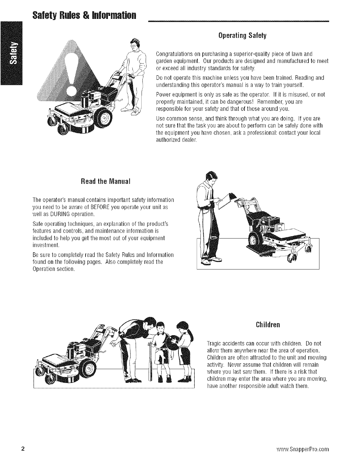
OperatingSafety
Congratulations on purchasing a superior-quality piece of lawn and
garden equipment. Our products are designed and manufactured to meet
or exceedall industry standards for safety.
Do not operatethis machine unless you have beentrained. Readingand
understanding this operator's manual is a way to train yourself.
Power equipment is only as safe asthe operator. If it is misused, or not
properly maintained, it can be dangerous! Remember,you are
responsible for your safety and that of those around you.
Use common sense, and think through what you are doing. If you are
not sure that the task you are about to perform can be safely done with
the equipment you have chosen ask a professional: contact your local
authorized dealer.
Read the Manual
The operator's manual contains important safety information
you needto be aware of BEFOREyou operate your unit as
well as DURINGoperation.
Safe operating techniques, an explanation of the product's
features andcontrols, and maintenanceinformation is
included to helpyou get the most out of your equipment
investment.
Be sure to completely readthe Safety Rulesand Information
found on the following pages. Also completely readthe
Operation section.
Children
Tragic accidents can occur with children. Do not
allow them anywherenear the areaof operation.
Children are often attractedto the unit and mowing
activity. Neverassume that children will remain
where you last saw them. If there is a risk that
children may enter the areawhere you are mowing,
haveanother responsibleadult watch them.
2 www.SnapperPro.com
SafetyRules& Iflformatiofl
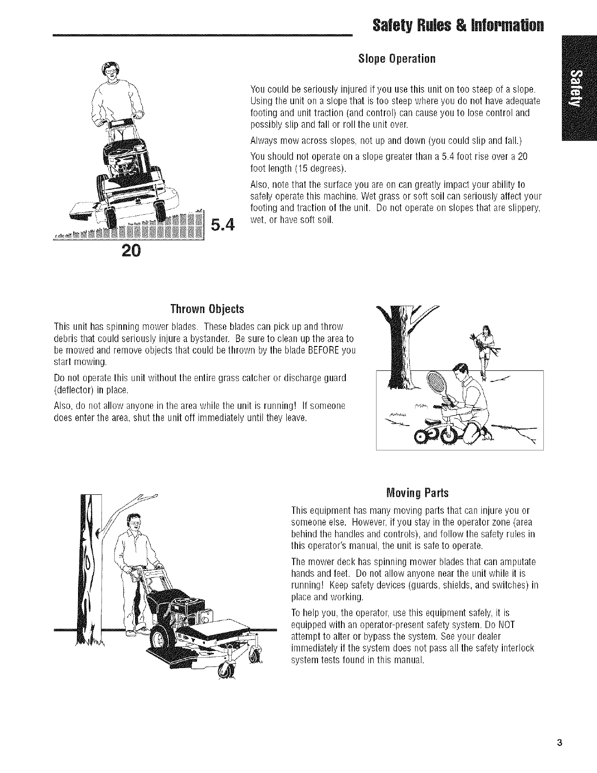
Slope Operation
2O
5.4
You could be seriously injured if you use this unit on too steep of a slope.
Usingthe unit on a slope that is too steep where you do not have adequate
footing and unit traction (and control) can cause you to lose control and
possibly slip and fall or roll the unit over.
Always mow across slopes, not up and down (you could slip and fall.)
You should not operate on a slope greater than a 5.4 foot rise over a 20
foot length (15 degrees).
Also, note that the surface you are on can greatly impact your ability to
safely operatethis machine. Wet grass or soft soil can seriously affect your
footing and traction of the unit. Do not operate on slopesthat are slippery,
wet, or havesoft soil.
Thrown Objects
This unit has spinning mower blades. Theseblades car/pick up and throw
debris that could seriously injure a bystander. Be sureto clean up tile areato
be mowed and remove objects that could bethrown by the blade BEFOREyou
start mowing.
Do not operate this unit without the entire grass catcher or discharge guard
(deflector) in place.
Also, do not allow anyone in the areawhile the unit is running! If someone
does enter the area. shut the unit off immediately until they leave.
Moving Parts
This equipment has many moving parts that can injure you or
someone else. However,if you stay in the operator zone (area
behind the handles and controls), and follow the safety rules in
this operator's manual,the unit is safeto operate.
The mower deck has spinning mower bladesthat can amputate
hands and feet, Do not allow anyone near the unit while it is
running! Keepsafetydevices (guards, shields, and switches) in
place and working.
To help you, the operator, use this equipment safely, it is
equippedwith an operator-present safety system. Do NOT
attempt to alter or bypass the system. Seeyour dealer
immediately if the system does not passall the safety interlock
system tests found in this manual.
Sa{etyRules& Ifl{ormUofl
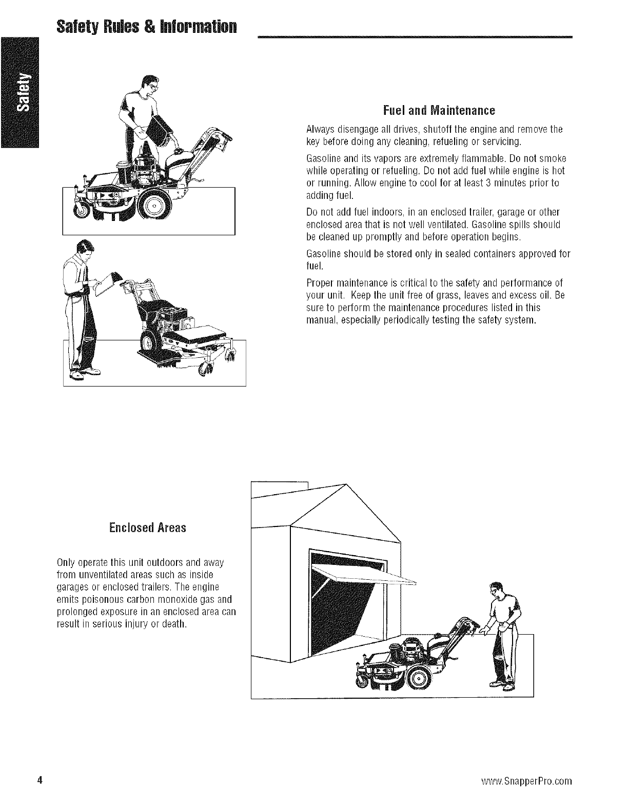
Fueland Maintenance
Always disengageall drives, shutoff the engine and removethe
key before doing any cleaning, refueling or servicing.
Gasoline and its vapors are extremely flammable. Do not smoke
while operating or refueling. Do not add fuel while engine is hot
or running. Allow engine to cool for at least 3 minutes prior to
adding fuel.
Do not add fuel indoors, in an enclosedtrailer, garage or other
enclosed areathat is not well ventilated. Gasoline spills should
be cleaned up promptly and before operation begins.
Gasoline should be stored only in sealed containers approved for
fuel.
Proper maintenanceis critical to the safety and performance of
your unit. Keepthe unit free of grass, leavesand excessoil. Be
sure to perform the maintenance procedures listed in this
manual, especially periodicallytesting the safety system.
Enclosed Areas
Only operatethis unit outdoors and away
from unventilated areas such as inside
garages or enclosedtrailers. The engine
emits poisonous carbon monoxide gas and
prolonged exposure in an enclosedarea can
result in serious injury or death.
4 www.SnapperPro.com
SsfetyRules& information
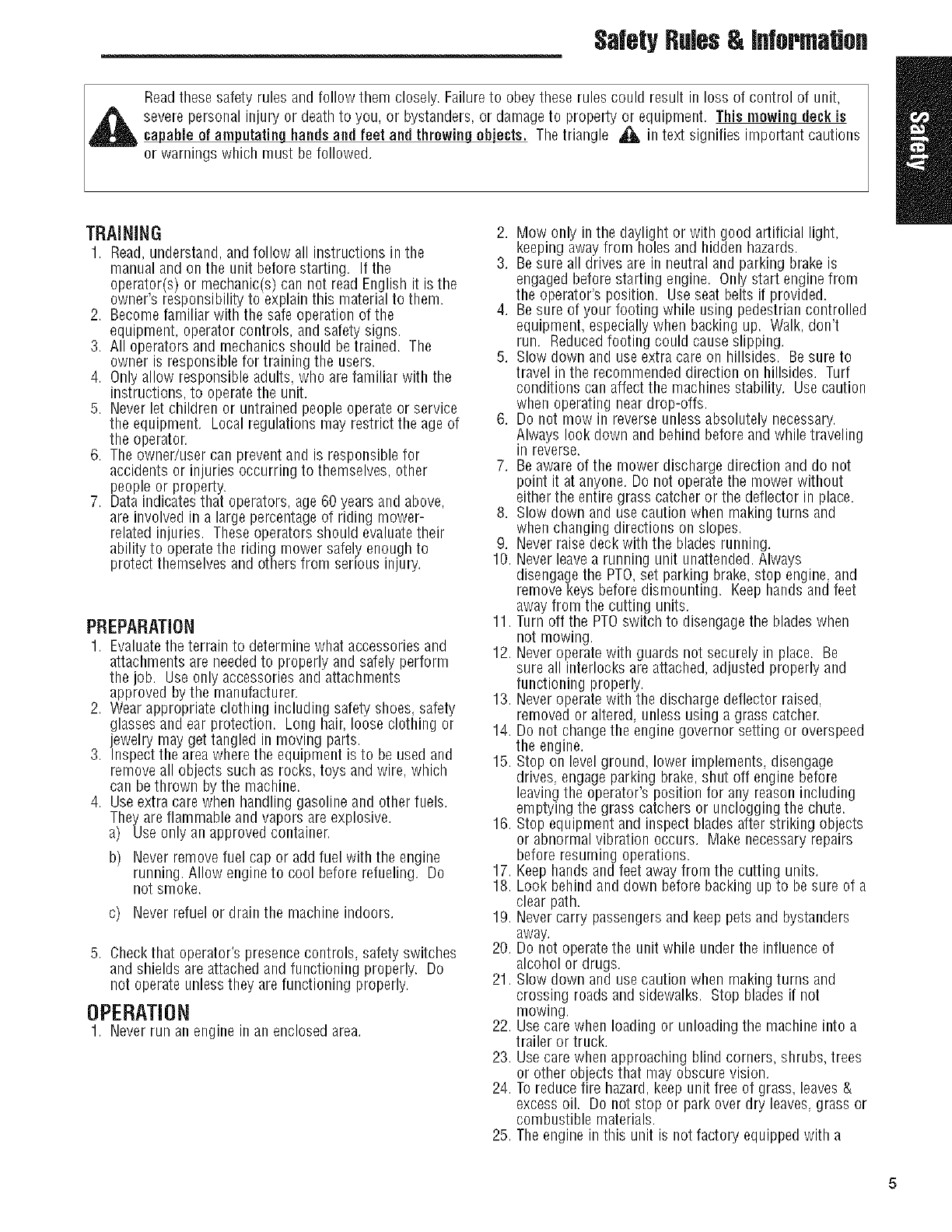
Readthese safety rules and follow them closely. Failureto obey these rules could result in loss of control of unit,
severe personal injury or death to you, or bystanders, or damage to property or equipment. This mowing deck is
capable of amputating hands and feet and throwin_ The triangle _ in text signifies important cautions
or warnings which must be followed.
TRAINING
1. Read,understand, and follow all instructions in the
manual and on the unit before starting. If the
operator e or mechanic s can not read English it is the
ownersresponsb tytoexpanthsmatera to them.
2. Becomefamiliar with the safeoperation of the
equipment, operator controls, and safety signs.
3. All operators and mechanics should betrained. The
owner is responsiblefor training the users.
4. Only allow responsible adults, who are familiar with the
instructions, to operate the unit.
5. Neverlet children or untrained people operate or service
the equipment. Local regulations may restrict the age of
the operator.
6. The owner/user can preventand is responsible for
accidents or injuries occurring to themselves, other
people or property.
7. Dataindicates that operators, age60 years and above,
are involved in a large percentageof riding mower-
related injuries. Theseoperators should evaluatetheir
ability to operate the riding mower safely enough to
protect themselves and others from serious injury.
PREPARATION
1. Evaluatethe terrain to determine what accessories and
attachments are neededto properly and safely perform
the job. Use only accessories and attachments
approved by the manufacturer.
2. Wear appropriate clothing including safety shoes, safety
glasses and ear protection. Long hair, loose clothing or
jewelry may get tangled in moving parts.
3. Inspect the areawhere the equipment is to be used and
removeall objects such as rocks, toys and wire, which
can be thrown by the machine.
4. Useextra care when handling gasoline and other fuels.
They are flammable and vapors areexplosive.
a) Useonly an approved container.
b) Neverremove fuel cap or add fuel with the engine
running. Allow engine to cool before refueling. Do
not smoke.
c) Neverrefuel or drain the machine indoors.
5. Checkthat operator's presencecontrols, safety switches
and shields are attached and functioning properly. Do
not operate unlessthe _are functioning properly.
OPERATION
1. Neverrun an engine In an enclosed area.
2. Mow only in the daylight or with good artificial light,
keeping awayfrom holes and hidden hazards.
3. Besure all drives are in neutral and parking brake is
engaged before starting engine. Only start engine from
the operator's position. Useseat belts if provided.
4. Besure of your footing while using pedestriancontrolled
equipment, especially when backing up. Walk, don't
run. Reducedfooting could causeslipping.
5. Slow down and use extra care on hillsides. Besure to
travel in the recommended direction on hillsides. Turf
conditions can affect the machines stability. Use caution
when operating neardrop-offs.
6. Do not mow in reverse unless absolutely necessary.
Always look down and behind before and while traveling
in reverse.
7. Beaware of the mower discharge direction and do not
point it at anyone. Do not operate the mower without
either the entire grass catcher or the deflector in place.
8. Slow down and use caution when makingturns and
when changing directions on slopes.
9. Neverraise deckwith the blades running.
10. Neverleave a running unit unattended. Always
disengage the PTO,set parking brake,stop engine, and
remove keys before dismounting. Keephands and feet
away from the cutting units.
11. Turn off the PTOswitch to disengage the blades when
not mowing.
12. Neveroperate with guards not securely in place. Be
sure all interlocks are attached,adjusted properly and
functioning properly.
13. Neveroperate with the discharge deflector raised,
removed or altered, unless using a grass catcher.
14. Do not change the engine governor setting or overspeed
the engine.
15. Stop on level ground, lower implements, disengage
drives, engageparking brake, shut off engine before
leaving the operator's position for any reason including
emptying the grass catchers or unclogging the chute.
16. Stop equipment and inspect blades after striking objects
or abnormal vibration occurs. Make necessaryrepairs
before resuming operations.
17. Keephands and feet awayfrom the cutting units.
18. Look behind and down before backing up to be sure of a
clear path.
19. Nevercarry passengers and keep pets and bystanders
away.
20. Do not operate the unit while underthe influence of
alcohol or drugs.
21. Slow down and use caution when makingturns and
crossing roads and sidewalks. Stop blades if not
mowing.
22. Usecare when loading or unloading the machine into a
trailer or truck.
23. Usecare when approaching blind corners, shrubs, trees
or other objects that may obscure vision.
24. To reduce fire hazard,keep unit free of grass, leaves&
excess oil. Do not stop or park over dry leaves,grass or
combustible materials.
25. The engine in this unit is not factory equippedwith a
SafetyRules& information
spark arrester. It is a violation of California Public
ResourceCode Section 4442 to use or operate the
engine on or near any forest-covered, brush-covered, or
grass-covered land unless the exhaust system is
equipped with a spark attester meeting any applicable
local or state laws. Other states or federal area may
have similar laws.
26. OSHAregulations may require the use of hearing
protection when exposedto sound levels greater than 85
dBA for an 8 hour time period.
tLCAUTION
This machine produces sound levels in
excess of 85 dBAat the operator's ear and
can cause hearing lossthoughextended
periods of exposure.
Wear hearingprotection when operating this machine.
SLOPEOPERATION
Slopesare a major factor relatedto loss-of-control and tip-
over accidents,which can result in severeinjury or death.All
slopes requireextra caution. If you cannot backupthe slope
or if you feel uneasyon it, do not drive on it.
, WARNING
Never operate on slopes greater than 15°which is a
rise of 5.4 feet (165 cm) vertically in 20 feet (607 cm)
horizontally.
Select slew ground speed before driving ontoslope.
Use extra cautionwhen operating on slopes with rear-
mounted grass catchers.
l/low across the face of slopes, not up and down, use
caution when changingdirections and DO NOTSTART
ORSTOPONSLOPE.
Do
1, Mow across slopes, not up and down.
2. Remove obstaclessuch as rocks, tree limbs, etc.
3. Watch for holes, ruts, or bumps. Uneventerrain could
overturn the unit. Tall grass can hide obstacles.
4. Useslow speed. Choosea slow speed so that you will
not have to stop or change speedwhile on the slope.
5. Useextra care with grass catchers or other attachments.
Thesecan change the stability of the unit.
6. Keepall movement on the slopes slow and gradual. Do
not make sudden changes in speed or direction.
7. Seeyour authorized dealerfor recommendations of
available weights to improve stability.
Do Not
1. Avoid starting, stopping, or turning on a slope. If tires
lose traction (i.e. machine stops forward motion on a
slope), disengagethe blade(s) (PTO) and drive slow off
the slope.
2. Do not turn on slopes unless necessary,and then, turn
slowly.
3. Do not mow near drop-offs, ditches, or embankments.
The operator could lose footing or balanceor mower
could suddenly turn over if a wheel is over the edge of a
cliff or ditch, or if an edge cavesin.
4. Do not mow on wet grass. Reducedfooting or traction
could causesliding.
5. Do not try to stabilize the unit by putting your foot on
the ground. (ride-on units)
6. Do not mow excessivelysteep slopes.
7. Do not use grass catcher on steep slopes.
TOWEDEQUIPMENT(RIDE-ONUNITS)
1. Tow only with a machinethat has a hitch designed for
towing. Do not attach towed equipment except at the
hitch point.
2. Follow the manufacturer's recommendations for weight
limit for towed equipment and towing on slopes. See
attaching a trailer under OPERATION.
3. Neverallow children or others in or on towed
equipment,
4. Onslopes, the weight of the towed equipment may
cause loss of traction and loss of control.
5. Travelslowly and allow extra distance to stop.
6. Do not shift to neutral and coast down hill.
CHILDREN
Tragicaccidentscan occur if the operator is not alert to the
presenceof children.Children areoften attractedto the unit
andthe mowing activity. Neverassumethat children will
remain whereyou lastsawthem.
1. Keepchildren out of the mowing areaand under the
watchful care of another responsible adult.
2. Bealert and turn unit off if children enter the area.
3. Before and during reverseoperation, look behind and
down for small children.
4. Neverallow children to operate the unit,
5. Useextra care when approaching blind corners, shrubs.
trees, or other objects that may obscure vision.
EMISSIONS
1. Engineexhaust from tHs product contains chemicals
known, in certain quantities, to cause cancer, birth
defects, or other reproductive harm.
2. Look for the relevant Emissions Durability Periodand Air
Index information onthe engine emissions label.
iGNiTiON SYSTEM (GASOLINE MODELS)
1. ThissparkignitionsystemcomplieswithCanadian
ICES-O02.
6 www.SnapperPro.com
SafetyRules& Iflformtiofl
SERVICEAND MAINTENANCE
Toavoid personal injuryor property damaqe, use extreme
care in handling gasoline. Gasoline is extremely flammable
and the vaporsare explosive.
Safe Handling of Gasoline
1. Extinguish all cigarettes, cigars, pipes, and other
sources of ignition.
2. Useonly approved gasoline containers.
3. Neverremove the gas cap or add fuel with the engine
running. Allow the engineto cool before refueling.
4. Neverfuel the machine indoors.
5. Neverstore the machine or fuel container where there is
an open flame, spark, or pilot light such as near a water
heater or other appliance.
6. Neverfill containers inside a vehicle or on a truck bed
with a plastic bed liner. Always place containers on the
ground away from your vehicle before filling.
7. Removegas-powered equipment from the truck or
trailer and refuel it on the ground. If this is not possible.
then refuel such equipment on a trailer with a portable
container, rather than from a gasoline dispenser nozzle.
8. Keepnozzlein contact with the rim of the fuel tank or
container opening at all times until fueling is complete.
Do not use a nozzlelock-open device.
9. If fuel is spilled on clothing, change clothing
immediately.
10. Neverover-fill the fuel tank. Replacegas capand
tighten securely.
11. Useextra care in handling gasoline and other fuels. They
are flammable and vapors are explosive.
12. If fuel is spilled, do not attempt to start the engine but
move the machine awayfrom the area of spillage and
avoid creating any source of ignition until fuel vapors
have dissipated.
13. Replaceall fuel tank capsand fuel container caps
securely.
Maintenance and Storage
1. Always observe safe refueling and fuel handling
practices when refueling the unit after transportation or
storage.
2. Always follow the engine manual instructions for storage
preparations before storing the unit for both short and
long term periods.
3. Always follow the engine manual instructions for proper
start-up procedureswhen returning the unit to service.
4. Neverstore the machine or fuel container inside where
there is an open flame, such as in a water heater. Allow
unit to cool before storing.
5. Shut off fuel while storing or transporting. Do not store
fuel near flames or drain indoors.
6. Keepall hardware,especially blade attachment bolts.
tight and keepall parts in good working condition.
Replaceall worn or damaged decals.
7. Nevertamper with safety devices. Check their proper
operation regularly.
8. Disengagedrives, lower implement, set parking brake,
stop engineand remove key or disconnect spark plug
wire. Wait for all movement to stop before adjusting,
cleaning or repairing.
9. Cleangrass and debris from cutting units, drives,
mufflers, and engineto prevent fires. Cleanup oil or
fuel spillage.
10. Let enginecool before storing and do not store near
flame.
11. Stop and inspect the equipment if you strike an object.
Repair,if necessary,before restarting.
12. Park machine on level ground. Neverallow untrained
personnel to service machine.
13. Usejack stands to support components when required.
14. Carefully releasepressure from components with stored
energy.
15. Disconnect battery or removespark plug wire before
making any repairs. Disconnect the negativeterminal
first and the positive last. Reconnectpositive first and
negativelast.
16. Usecare when checking blades. Wrap the blade(s) or
wear gloves, and use caution when servicing them.
Only replace blades. Neverstraighten or weld them.
17. Keephands and feet awayfrom moving parts. If
possible, do not makeadjustments with the engine
running.
18. Chargebatteries in an open well ventilated area, away
from spark andflames. Unplug charger before
connecting or disconnecting from battery. Wear
protective clothes and use insulated tools.
19. Grasscatcher components are subject to wear,damage,
and deterioration, which could expose moving parts or
allow objects to bethrown. Frequentlycheck
components and replacewith manufacturer's
recommended parts, when necessary.
20. Checkbrake operation frequently. Adjust and service as
required.
21. Useonly factory authorized replacement parts when
making repairs.
22. Always comply with factory specifications on all settings
and adjustments.
23. Only authorized service locations should be utilized for
major service and repair requirements.
24. Neverattempt to makemajor repairs on this unit unless
you have been properly trained. Improper service
procedures can result in hazardous operation,
equipment damage and voiding of manufacturer's
warranty.
25. Units with hydraulic pumps, hoses, or motors:
WARNING:Hydraulic fluid escaping under pressure may
have sufficient force to penetrateskin and causeserious
injury. If foreign fluid is injected into the skin it must be
surgically removed within a few hours by a doctor
familiar with this form of injury or gangrenemay result.
Keepbody and hands awayfrom pin holes or nozzles
that eject hydraulic fluid under high pressure. Use paper
or cardboard, and not hands,to search for leaks. Make
sure all hydraulic fluid connections are tight and all
hydraulic hosesand lines are in good condition before
applying pressureto the system. If leaks occur, have
the unit serviced immediately by your authorized dealer.
26. WARNING:Stored energy device. Improper releaseof
springs can result in serious personal injury. Springs
should be removed by an authorizedtechnician.
OperatorSafety
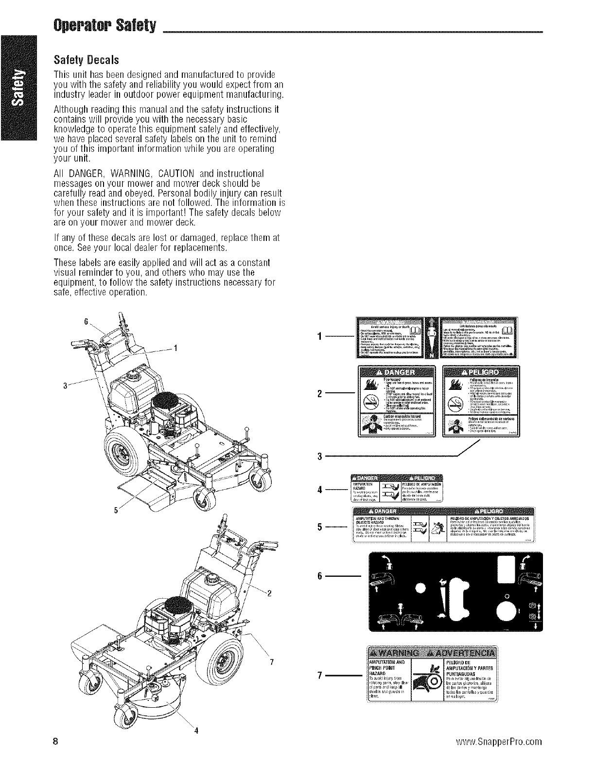
Safety Decals
Thisunithasbeendesignedandmanufacturedto provide
youwiththesafetyandreliabilityyouwouldexpectfrom an
industryleaderin outdoorpowerequipmentmanufacturing.
Although reading this manual and the safety instructions it
contains will provide you with the necessary basic
knowledge to operatethis equipment safely and effectively,
we have placed several safety labels on the unit to remind
you of this important information while you are operating
your unit.
All DANGER,WARNING, CAUTION and instructional
messageson your mower and mower deckshould be
carefully read and obeyed. Personal bodily injury can result
when these instructions are not followed. The information is
for your safetyand it is important! The safety decals below
are on your mower and mower deck.
If any of these decals are lost or damaged, replacethem at
once. Seeyour local dealerfor replacements.
Theselabels are easilyapplied and will act as a constant
visual reminder to you, and others who may usethe
equipment, to follow the safety instructions necessaryfor
safe, effective operation.
J
7
7
\
\\\ 4
8 www.SnapperPro.com
OperatorSafety
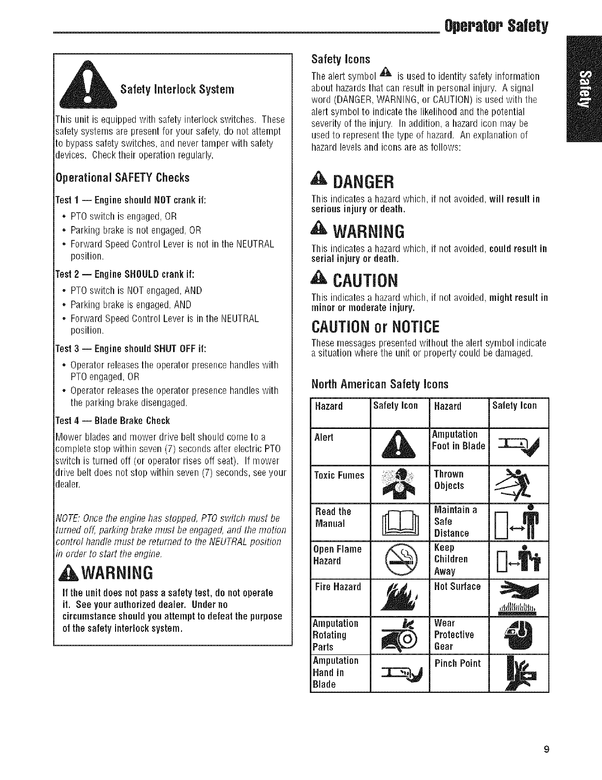
SafetyinterlockSystem
this unit is equipped with safety interlockswitches. These
_afetysystems are presentfor your safety, do not attempt
:o bypass safety switches, and never tamper with safety
Jevices. Check their operation regularly.
Operational SAFETYChecks
rest 1 -- Engine shouldNOTcrank if:
,, PTOswitch is engaged,OR
,, Parking brake is not engaged,OR
,, Forward SpeedControl Lever is not in the NEUTRAL
position.
rest 2 -- EngineSHOULDcrankif:
,, PTOswitch is NOTengaged,AND
,, Parking brake is engaged,AND
,, Forward SpeedControl Lever is in the NEUTRAL
position.
rest 3 -- EngineshouldSHUT OFFif:
', Operator releasesthe operator presencebandies witb
PTOengaged,OR
• Operator releasesthe operator presencehandles with
the parking brake disengaged.
rest 4 -- Blade BrakeCheck
_ower blades and mower drive belt should come to a
:;ompletestop within seven (7) seconds after electric PTO
_witch is turned off (or operator rises off seat). If mower
Jrive belt does not stop within seven (7) seconds, see your
Jealer.
_IOTE:Once the enginehas stopped, PTOswitch must be
turned off, parking brake must be engaged,and the motion
:ontml handlemust be returned to the NEUTRALposition
_norder to start the engine,
, WARNING
if the unit does notpassa safety test, do notoperate
it. See your authorized dealer. Underno
circumstanceshouldyou attempt to defeat the purpose
of the safety interlocksystem.
Safety icons
The alert symbol '_ is used to identity safety information
about hazardsthat can result in personal injury. A signal
word (DANGER,WARNING,or CAUTION)is used with the
alert symbol to indicatethe likelihood and the potential
severity of the injury. In addition, a hazardicon may be
used to represent the type of hazard. An explanation of
hazard levels and icons are as follows:
DANGER
This indicates a hazardwhich, if not avoided, will result in
serious injury or death.
WARNING
This indicates a hazardwhich, if not avoided, could result in
serial injury or death.
CAUTION
This indicates a hazardwhich, if not avoided, might result in
minor or moderate injury.
CAUTIONor NOTICE
Thesemessages presentedwithout tbe alert symbol indicate
a situation wherethe unit or property could be damaged.
North American Safety Icons
Hazard Safety icon Hazard Safety icon
Alert _ Amputation _---"1_
Foot in Blade
ToxicFumes _ThrOwnObjects
Read the Maintain a •
Manual [[_ Safe _ _"">T
Distance
OpenFlame @ Keep [_ ,_,_
Hazard Children
Away
Fire Hazard _,_ Bat Surface _
,JI_IIII_IN}I)_,
Amputation _) Wear
Rotating Protective
Parts Gear
AmputatiOnHandin _r_%'_ PinchPoint I_11
Blade A
9
OperatorSafety
Featuresand Controls
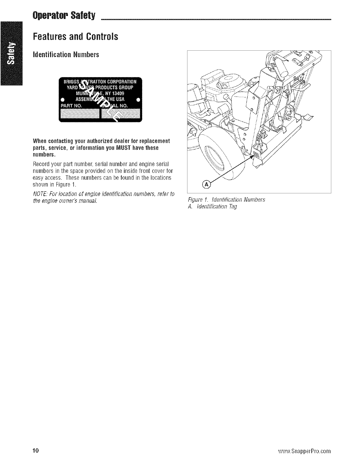
Identification N.rnbers
When contactingyourauthorized dealer for replacement
parts, service, or informationyou MUST have these
numbers.
Recordyour part number, serial number and engine serial
numbers in the space provided on the inside front cover for
easyaccess. These numbers can be found in the locations
shown in Figure 1.
NOTE,For locationof engineidentification numbers, refer to
the engine owner's manual. Figure 1. Identification Numbers
A. Identification Tag
10 www.SnapperPro.com
,FeaturesandControls
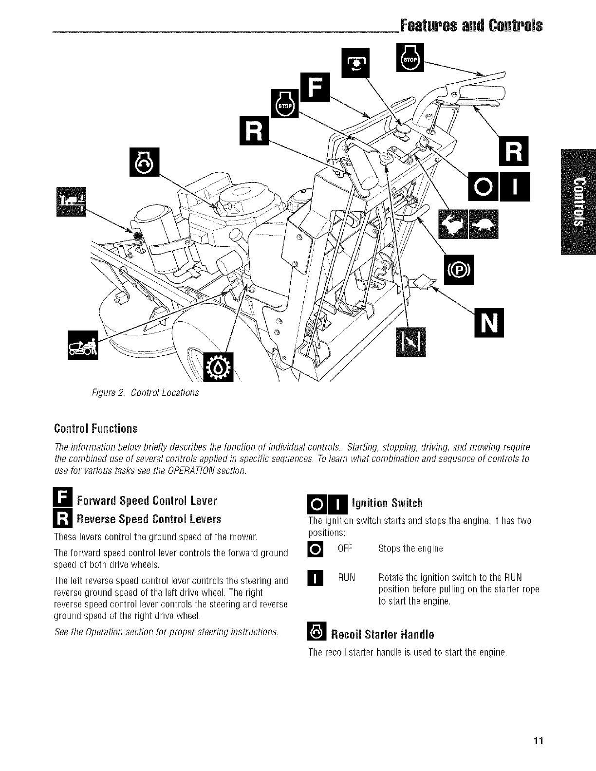
Figure 2, Control Locations
Control Functions
Theinformation below briefly describes the tiJnctionof individual controls. Starting, stopping, driving, and mowing require
the combined use of several controls applied in specific sequences. Tolearn what combination and sequenceof controls to
use for various tasks see the OPERATIONsection.
_F_ Forward Speed Control Lever
r--'_ Reverse Speed Control Levers
Theseleverscontrol the ground speed of the mower,
The forward speed control levercontrols the forward ground
speed of both drive wheels.
The left reverse speed control lever controls the steering and
reverse ground speed of the left drive wheel. The right
reverse speed control lever controls the steering and reverse
ground speed of the right drive wheel.
Seethe Operationsection for proper steering instructions.
BO ignition Switch
The ignition switch starts and stops the engine, it has two
positions:
] OFF Stops the engine
] RUN Rotatethe ignition switch to the RUN
position before pulling on the starter rope
to start the engine.
r__ Recoil Starter Handle
The recoil starter handle is used to start the engine.
11
Features&Centrols
ParkingBrake
DISENGAGE Releasesthe parking brake.
[ ENGAGE Locks the parking brake.
Pullthe parking brake handleup to engagethe parking
brake. Push the parking brake handle down to disengage
the parking brake. NOTE,Tostart the unit the parking brake
must be engaged.
[PTO (Power TakeOff) Switch
The PTOswitch engagesand disengagesthe mower. Pull UP
on the switch to engage,and push DOWNto disengage.
r_ Neutral Return Pedal
The neutral return pedal provides a hands-free return to
neutral. The pedal is used in conjunction with the Reverse
SpeedControl Leversto properly stop the machine.
Seethe Operationsection for Driving Instructions.
ThrottleControl
The throttle controls the engine speed. Movethe throttle
control forward towards the FASTposition to increasethe
engine speed and back towards the SLOW position to
decreasethe enginespeed. Always operate at FULLthrottle.
FAST Speeds up the engine speed.
SLOW Slows down the engine speed.
Fuel Tank Cap
To remove the cap, turn counterclockwise.
Engine Kill /Operator Presence Handles
Thesehandles are a major factor in the safety interlock
system of the mower. Both handles are tied together so
depressing one handledepresses both. The operator must
depressthe handles in order to deactivatethe engine kill
system. Handlesmust bedepressed to disengage the
parking brake and engagethe PTOswitch.
Transmission Release Valves
The transmission release leversdeactivatethe transaxle so
that the unit can be pushed by hand. SeePUSHINGTHE
UNIT BY HANDfor operational information.
TransmissionOil Fill
Transmission oil is addedthrough the transmission oil
reservoirs. It also serves as extra holding capacity for oil as
the transmissions heat up and the oil expands. SeeCHECK
TRANSMISSIONOIL for oil level check andfill procedures.
[]Choke Control
Closethe choke for cold starting. Openthe choke once the
engine starts. A warm engine may not requirechoking. Pull
the knob UP to close the choke. Push the knob DOWNto
open the choke.
Cutting HeightAdjustment Handles
The cutting height adjustment handles control the mower
deck cutting height. To raise the mower deck cutting height
crank the cutting height adjustment handlesclockwise. To
lower the mower deck cutting height, crank the cutting
height adjustment handles counter-clockwise. To ensure an
even cut, both cutting height adjustment handles must be
adjusted to the same height.
12 www.SnapperPro.com

Operatiofl
Operation
GeneralOperatingSafety
Before first time operation:
,. Besure to read all information in the Safety and
Operationsections before attempting to operate this
unit.
,. Becomefamiliar with all of the controls and how to stop
the unit.
,. Drive in an open areawithout mowing to become
accustomed to the unit.
AWARNING
Never operate on slopesgreater than 15°which is a
rise of 5.4 feet (1,6 m) vertically in 20 feet (607 cm)
horizontally.
Select a slowground speedbefore driving onto a
slope.
Mow across the face of slopes, not up and down, use
cautionwhen changingdirections and DO NOTSTART
ORSTOPONSLOPE.
_WARNING
Beforeleavingthe operator'sposition for any reason,
engagethe parking brake, disengage the PTO,stopthe
engineand removethe key.
Toreducefire hazard, keepthe engine, unit free of
grass, leaves and excessgrease. Do notstopor park
unit overdry leaves, grass or combustiblematerials.
Gasolineis highlyflammable and must be handled
with care. Never fill the tank when the engineis still
hot from recent operation. Donotallow open flame,
smokingor matchesin the area. Avoid over-fillingand
wipe up any spills.
Checks Before Starting
,. Checkthat crankcaseis filled to full mark on the engine
oil dipstick (B, Figure3). Seethe engine Operator's
Manual for instructions and oil recommendations.
,. Fill the fuel tank (A) with fresh fuel. Referto engine
manual for fuel recommendations.
,. Makesure all nuts, bolts, screws and pins are in place
and tight.
,. Checkthe tire pressures. See Check Tire Pressures.
,. Checkthe hydraulic oil tank (C) and make sure that the
oil level is up to the FULLCOLDmark.
,. Adjust the height of the mower deck to the desired
position. SeeMowing Height Adjustment,
Figure 3. Pro-start Checks
A. Fuel TankFiller Neck
B, Engine Oil Dipstick
C, Hydraufic Oil Fill
13
Operation
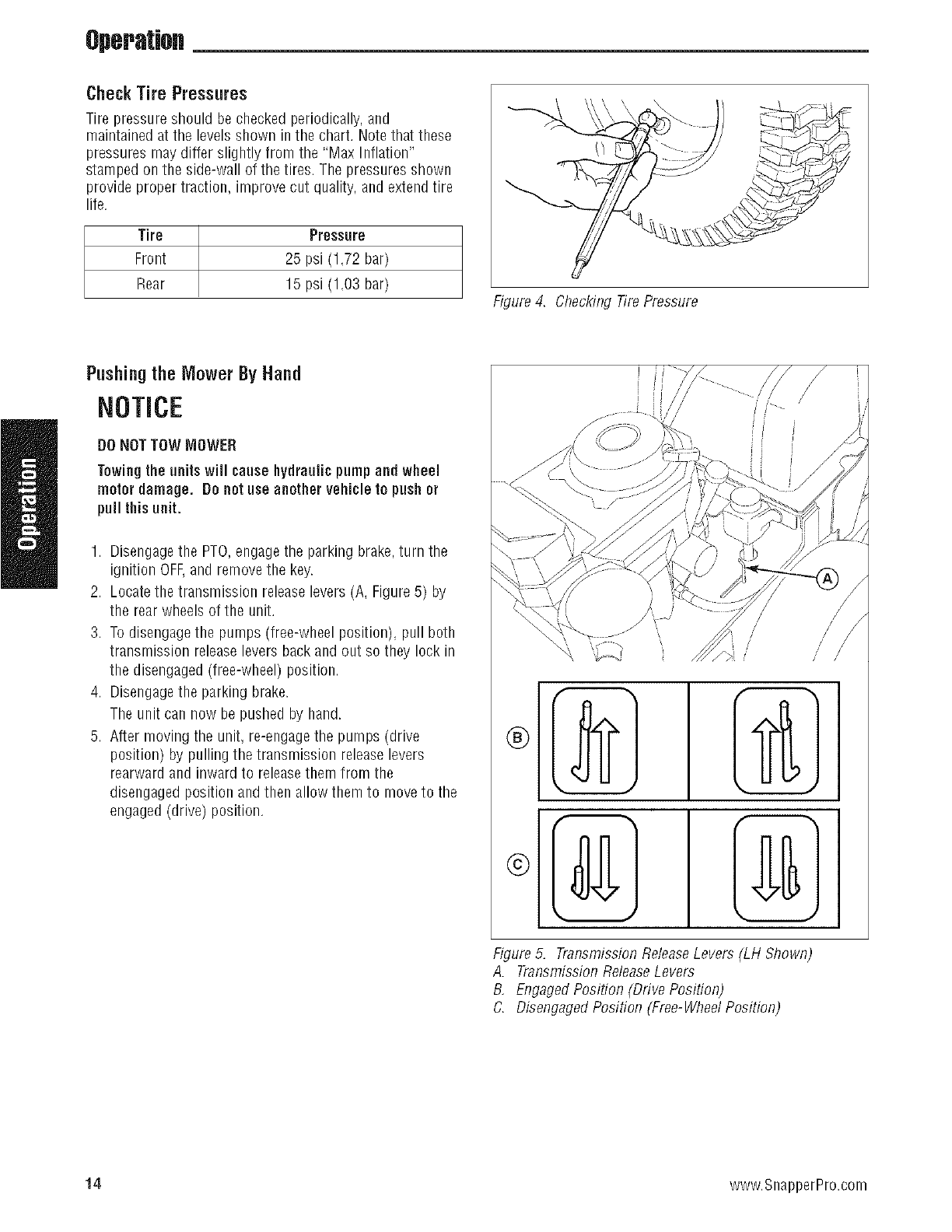
CheckTire Pressures
Tire pressure should bechecked periodically, and
maintained at the levels shown in the chart. Note that these
pressures may differ slightly from the "Max Inflation"
stamped on the side-wall of the tires. The pressures shown
provide proper traction, improve cut quality, and extendtire
life.
Tire Pressure
Front 25 psi (1,72 bar)
Rear 15 psi (1,03 bar) Figure 4. Checking Tire Pressure
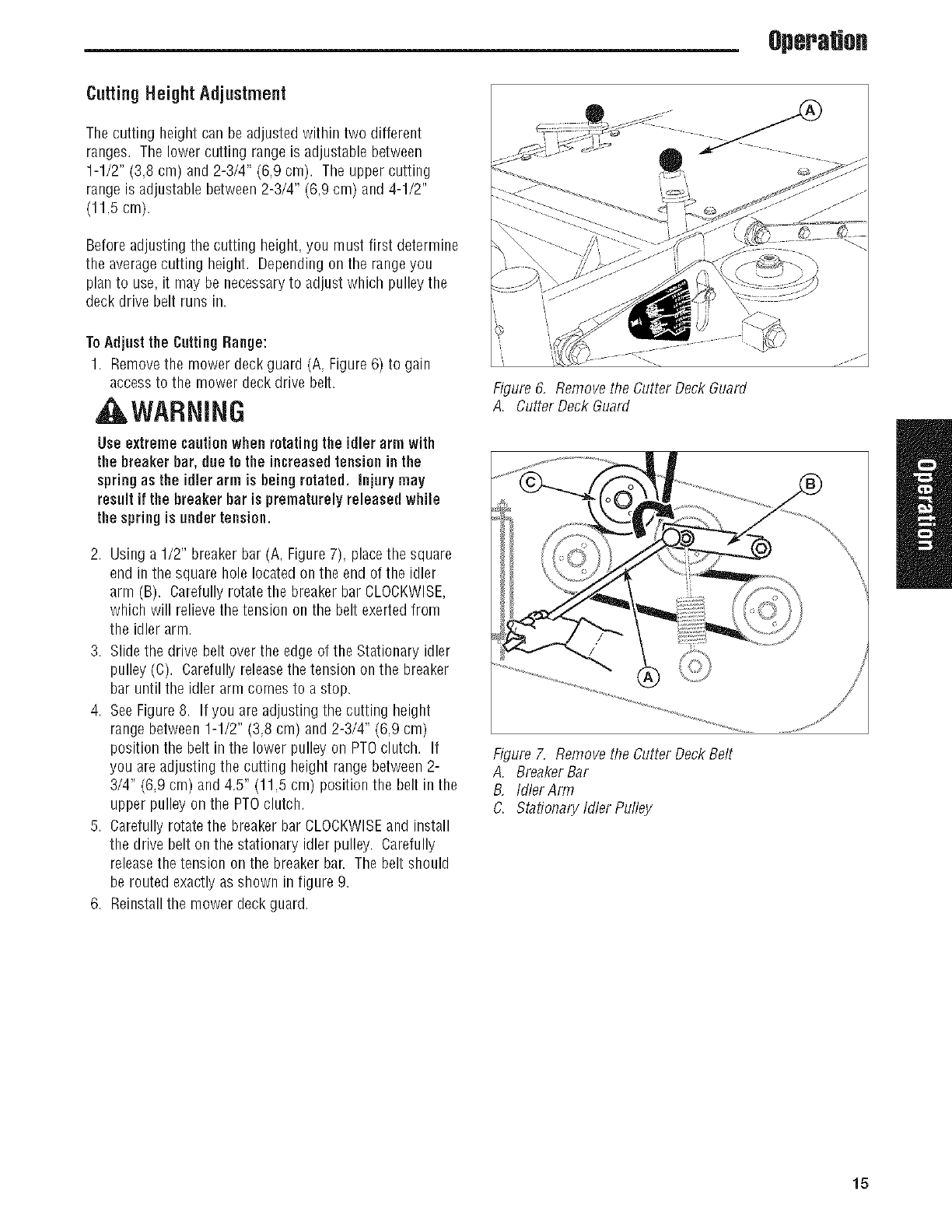
Pushing the Mower By Hand
NOTICE
DONOTTOW MOWER
Towingthe units will causehydraulic pumpand wheel
motor damage. De nat use another vehicle to push or
pull this unit.
1. Disengagethe PTO,engagethe parking brake,turn the
ignition OFEand remove the key.
2. Locatethe transmission release levers (A, Figure 5) by
the rear wheels of the unit.
3. To disengagethe pumps (free-wheel position), pull both
transmission releaselevers back and out so they lock in
the disengaged(free-wheel) position.
4. Disengagethe parking brake.
The unit can now be pushed by hand.
5. After moving the unit, re-engagethe pumps (drive
position) by pulling the transmission releaselevers
rearward and inward to releasethem from the
disengaged position andthen allow them to moveto the
engaged (drive) position.
I
t
I
J
Figure 5. Transmission ReleaseLevers (LH Shown
A. Transmission ReleaseLevers
B, EngagedPosition (Drive Position)
C. DisengagedPosition (Free-WheelPosition)
,/
//
/
14 www.SnapperPro.com
Operatiofl
CuttingHeightAdjustment
The cutting height can be adjusted within two different
ranges. The lower cutting rangeis adjustable between
1-1/2" (3,8 cm) and 2-3/4" (6,9 cm). The upper cutting
range is adjustable between 2-3/4" (6,9 cm) and 4-1/2"
(11,5 cm).
Before adjusting the cutting height, you must first determine
the averagecutting height. Depending on the rangeyou
plan to use, it may be necessaryto adjust which pulley the
deck drive belt runs in.
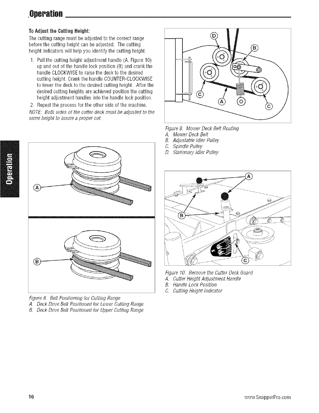
ToAdjust the CuttingRange:
1. Removethe mower deck guard (A, Figure6) to gain
access to the mower deck drive belt.
, ,WARNING
Use extremecautionwhen rotating the idler arm with
the breaker bar, due to the increasedtensionin the
spring as the idler arm is being rotated, injury may
result if the breaker bar is prematurely released while
the spring is under tension.
2. Using a 1/2" breaker bar (A, Figure 7), placethe square
end in the square hole locatedon the end of the idler
arm (B). Carefully rotate the breaker bar CLOCKWISE,
which will relieve the tension on the belt exerted from
the idler arm.
3. Slidethe drive belt over the edge of the Stationary idler
pulley (C). Carefully releasethe tension on the breaker
bar until the idler arm comes to a stop.
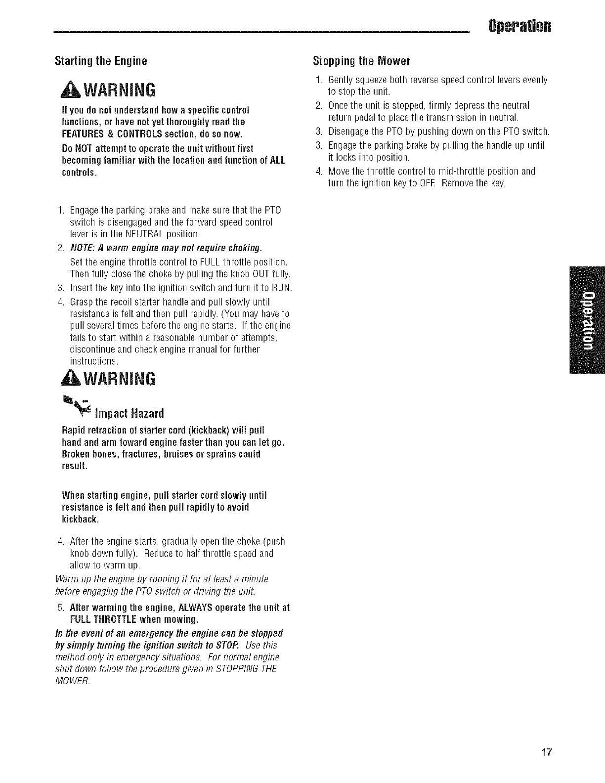
4. SeeFigure 8. If you are adjusting the cutting height
range between1-1/2" (3,8 cm) and 2-3/4" (6,9 cm)
position the belt in the lower pulley on PTOclutch. If
you areadjusting the cutting height range between2-
3/4" (6,9 cm) and 4.5" (11,5 cm) position the belt in the
upper pulley on the PTOclutch.
5. Carefully rotate the breaker bar CLOCKWISEand install
the drive belt on the stationary idler pulley. Carefully
releasethe tension on the breaker bar. The belt should
be routed exactly as shown in figure 9.
6. Reinstall the mower deck guard.
Figure 6, Remove the Cutter Deck Guard
A. Cutter Deck Guard
Figure 7. Remove the Cutter Deck Belt
A. Breaker Bar
B, Idler Arm
C. Stationary Idler Pulley
15
,Operation
ToAdjust the gutting Height:
The cutting range must be adjusted to the correct range
before the cutting height can beadjusted. The cutting
height indicators will help you identify the cutting height.
1. Pull the cutting height adjustment handle (A, Figure 10)
up and out of the handle lock position (B) and crank the
handle CLOCKWISEto raise the deckto the desired
cutting height. Crankthe handle COUNTER-CLOCKWISE
to lower the deck to the desired cutting height. After the
desired cutting heights are achievedposition the cutting
height adjustment handles into the handle lock position.
2. Repeatthe process for the other side of the machine.
NOTE, BoB1sides of the cutter deck must be adjusted to the
same height to insure a proper cut.
Figure 8. Belt Positioning for Cutting Range
A. Deck DriveBelt Positioned for Lower Cutting Range
B. Deck Drive Belt Positioned for Upper Cutting Range
Figure 9. Mower Deck Belt Routing
A. Mower Deck Belt
B, Adjustable Idler Pulley
C. Spindle Pulley
D. Stationary Idler Pulley
Figure 10. Remove the Cutter Deck Guard
A. Cutter Height Adjustment Handle
B, Handle Lock Position
C. Cutting Height Indicator
16 www.SnapperPro.com
Operation
Starting the Engine
AWARNING
if youde net understandhow a specificcontrol
functions, or havenotyet thoroughlyread the
FEATURES&CONTROLSsection, do so new.
DoNOTattempt to operate the unit without first
becoming familiar with the locationand function ofALL
controls.
1. Engagethe parking brake and make sure that the PTO
switch is disengaged and the forward speed control
lever is in the NEUTRALposition.
2. NOTE:A warm enginemay not require choking.
Set the enginethrottle control to FULLthrottle position,
Then fully close the choke by pulling the knob OUTfully.
3. Insert the key into the ignition switch and turn it to RUN.
4. Graspthe recoil starter handle and pull slowly until
resistance is felt and then pull rapidly. (You may haveto
pull severaltimes before the engine starts. If the engine
fails to start within a reasonablenumber of attempts,
discontinue and check engine manual for further
instructions.
, WARNING
_impactHazard
Rapid retractionof startercord(kickback) will pull
handand arm toward engine faster thanyou can let go.
Broken bones, fractures, bruises orsprainscould
result.
Stopping the Mower
1. Gentlysqueezeboth reversespeed control levers evenly
to stop the unit.
2. Oncethe unit is stopped, firmly depressthe neutral
return pedalto placethe transmission in neutral.
3. Disengagethe PTOby pushing down on the PTOswitch.
3. Engagethe parking brake by pulling the handleup until
it locks into position.
4. Move the throttle control to mid-throttle position and
turn the ignition keyto OFE Removethe key.
When startingengine, pull starter cordslowly until
resistanceis felt and then pull rapidlyto avoid
kickback.
4. After the engine starts, gradually open the choke (push
knob down fully). Reduceto half throttle speed and
allow to warm up.
Warm up the engineby running it for at least a minute
before engaging the PTOswitch or driving the uniL
5. After warming the engine, ALWAYSoperate the unit at
FULLTHROTTLEwhen mowing.
In the eventof an emergencythe enginecan he stopped
hy simply turning the ignition switch to STOP. Use this
method only in emergencysituations. For normal engine
shut down follow the procedure given in STOPPINGTHE
MOWER,
17
Operation
DrivingThe Mower
NOTE: Before attempting to drive the mower make sure you
have read the Featuresand Controls section and understand
the location and function of the controls.
The hydrostatic transmission has an infinite number of
speeds betweenfull speed forward and reverse, with the
faster speeds being achievedby moving the forward speed
control lever and reversespeed control leversfarthest in the
direction of travel.
For normal use, the throttle should be kept fully open and
the ground speed of the machine determined by the forward
speed control lever. When transporting the machine or when
loading or unloading from a truck or trailer, partial throttle
should be used to slow the reaction time of the controls and
reduce noise.
Practice maneuveringthe machineat a slow engine speed on
level ground with the PTOswitch in the "OFF"position until
you are familiar with the controls.
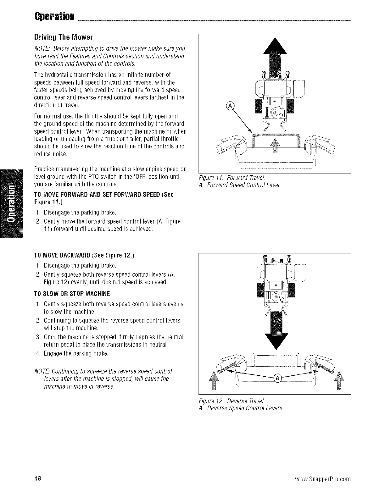
TO MOVEFORWARDAND SETFORWARDSPEED(See
Figure 11.)
1. Disengagethe parking brake.
2. Gentlymove the forward speed control lever (A, Figure
11) forward until desired speed is achieved.
\
Figure 11. Forward Travel
A. Forward SpeedControl Lever
TO MOVEBACKWARD(See Figure12.)
1. Disengagethe parking brake.
2. Gentlysqueezeboth reversespeed control levers (A,
Figure 12) evenly, until desired speed is achieved.
TO SLOW ORSTOP MACHINE
1. Gentlysqueezeboth reversespeed control levers evenly
to slow the machine.
2. Continuing to squeezethe reverse speedcontrol levers
will stop the machine.
3. Oncethe machine is stopped, firmly depress the neutral
return pedalto placethe transmissions in neutral.
4. Engagethe parking brake.
NOTE,Continuing to squeezethe reverse speed control
levers after the machine is stopped, will causethe
machine to move in reverse.
|
Figure 12. Reverse Travel
A. ReverseSpeedControl Levers
18 www.SnapperPro.com
Operatiofl
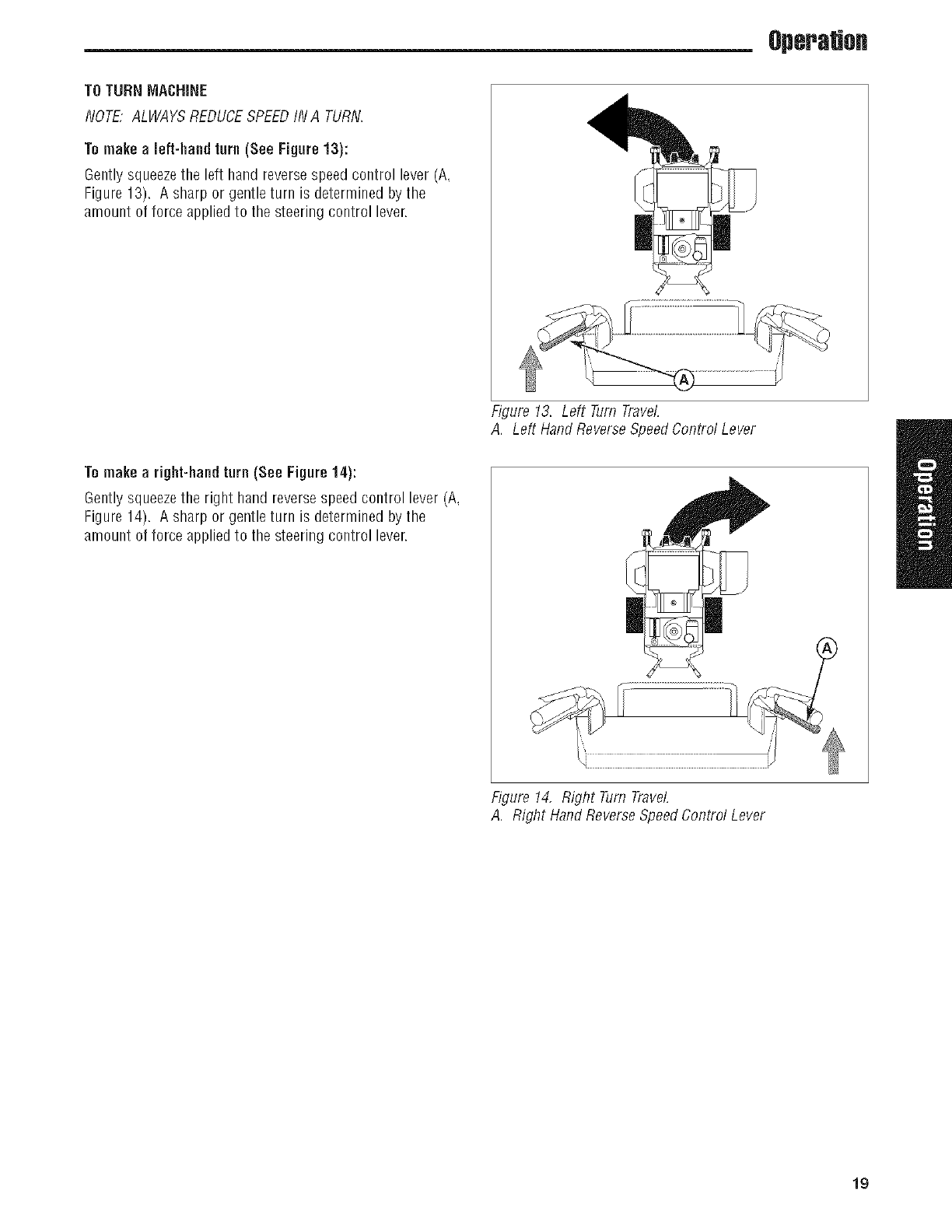
TO TURNMACHINE
NOTE"ALWAYSREDUCESPEEDIN A TURN
Tomake a left-hand turn (See Figure 13):
Gently squeezethe left hand reversespeed control lever (A,
Figure 13) A sharp or gentle turn is determined by the
amount of force appliedto the steering control lever
Figure 13 Left Turn Travel
A Left Hand Reverse SpeedControl Lever
Tomake a right-handturn (See Figure 14):
Gently squeezethe right hand reversespeed control lever (A,
Figure 14) A sharp or gentle turn is determined by the
amount of force appliedto the steering control lever i
Figure 14, Right Turn Travel
A Right Hand Reverse SpeedControl Lever
19
Operation
Mowing
Before mowing, set the cutting height as described in
CUTTINGHEIGHTADJUSTMENT.
1. Engagethe parking brake. Make sure the PTOswitch is
disengaged and the forward speed control lever is in the
NEUTRALposition
2. Start the engine (see Starting The Engine).
3. Set the throttle to FULL.
4. Engagethe PTOby pulling up on the PTOswitch.
5. Begin mowing. See Mowing Recommendationsfor tips
on mowing patterns, lawn care, and trouble shooting
information.
6. When finished, shut off the PTOby pushingthe PTO
switch down completely.
7. Stop the engine (see Stopping TheEngine).
Mowing Recommendations
Severalfactors can affect how well your machine cuts grass,
Following proper mowing recommendations can improve
the performance and life of your machine.
Heightof Grass
Often cutting height is a matter of personal preference.
Typically,you should mow the grass when it is is between
three and five inches high. The proper cutting height range
for a specific lawn will depend upon several factors,
including the type of grass, the amount of rainfall, the
prevailing temperature, and the lawn's overall condition.
Cutting the grass too short causes weak, thin grass plants,
which are easily damaged by dry periods and pests. Cutting
too short is often more damaging than allowing the grass to
be slightly higher.
Letting grass grow a bit longer--especially when it is hot
and dry--reduces heat build-up, preserves neededmoisture
and protects the grass from heat damage and other
problems. However,allowing grass to grow too high can
causethin turf and additional problems.
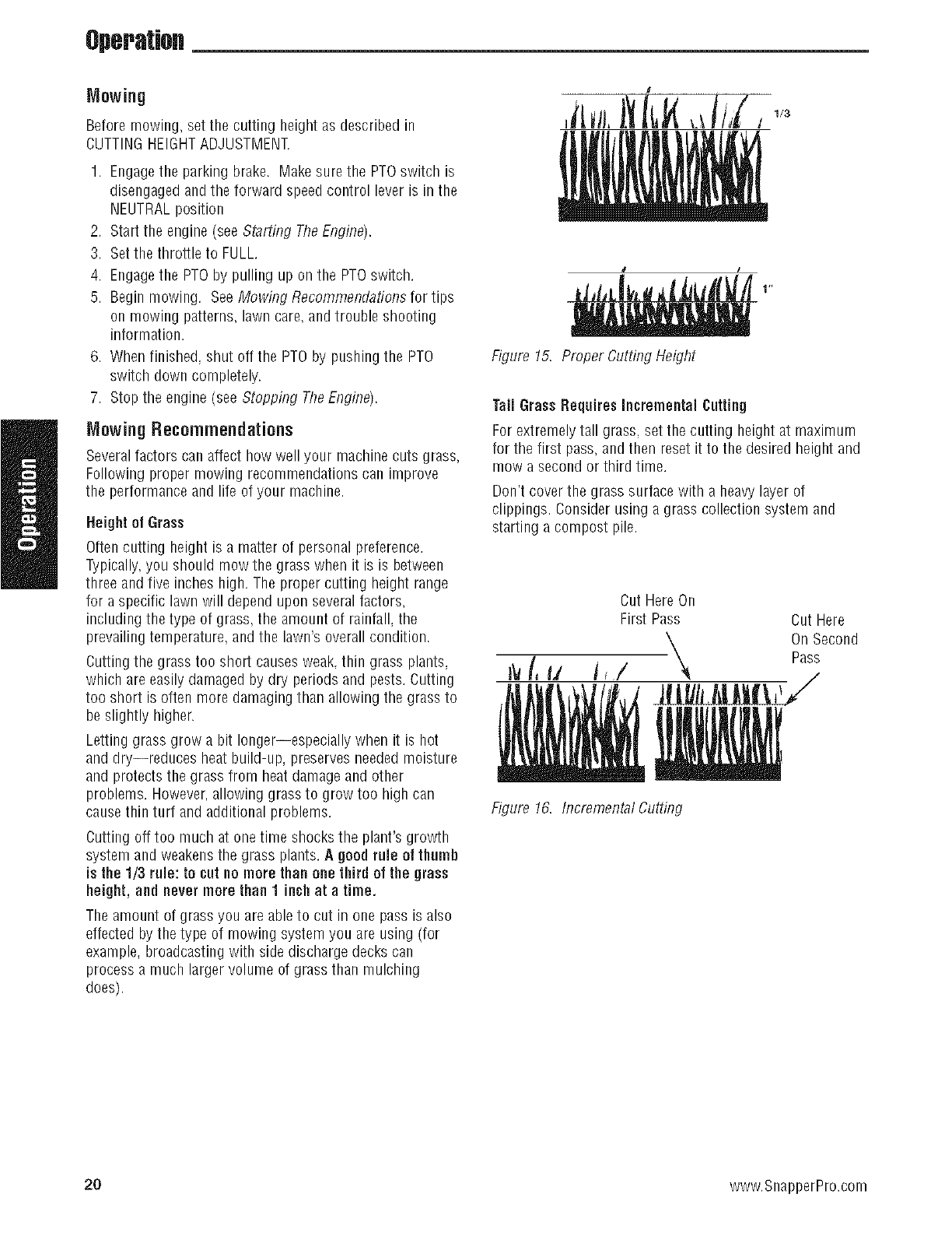
Cutting off too much at one time shocks the plant's growth
system and weakens the grass plants. A good rule of thumb
is the 1/3 rule: to cut nomore thanone third of the grass
height, and nevermare than 1 inch at a time.
The amount of grass you are ableto cut in one pass is also
effected by the type of mowing system you are using (for
example, broadcasting with side discharge decks can
process a much larger volume of grass than mulching
does).
I
Figure 15. Proper Cutting Height
Tall GrassRequires Incremental Cutting
For extremely tall grass, set the cutting height at maximum
for the first pass, andthen reset it to the desired height and
mow a second or third time.
Don't cover the grass surface with a heavy layer of
clippings. Consider using a grass collection system and
starting a compost pile.
Cut HereOn
First Pass Cut Here
__ On Second
_j/, Pass
Figure 16. IncrementalCutting
20 www.SnapperPro.com
Operatiofl
When and HowOften to Mow
The time of day and condition of the grass greatly affect the
results you'll get when mowing. For the best results, follow
these guidelines:
1. Mow when the grass is betweenthree and five inches
high.
2. Mow with sharp blades. Short clippings of grass one
inch or shorter decompose more quickly than longer
blades.Sharp mower blades cut grass cleanly and
efficiently, preventing frayed edgeswhich harm the
grass.
3. Mow at time of day when the grass is cool and dry. Late
afternoon or early evening often provide these ideal
mowing conditions.
4. Avoid mowing after rain or even heavy dew,and never
mulch when the grass is wet (moist grass does not
mulch well, and clumps beneaththe mower deck).
Mowing Patterns
Always start mowing on a smooth, level area.
The size and type of areato be mowedwill determine the
best mowing pattern to use. Obstructions such as trees,
fences and buildings, and conditions such as slopes and
grades must also be considered.
1. Cut long straight strips overlapping slightly.
2. Where possible, change patterns occasionallyto
eliminate matting, graining or a corrugated appearance.
3. For a truly professional cut, mow across the lawn in one
direction, then recut the lawn by mowing perpendicular
to the previous cut.
Note:Alwaysoperate the engine at full throttle when
mowing,
If you hearthe engine slowing down, you are mowing too
fast--using a slower ground speed will improve the cutting
efficiency of the blades and prevents many common cutting
problems. Usean appropriate ground speed for the
thickness and height of the grass you arecutting (3rd gear
or slower for manual gear models). If you hearthe engine
slowing down you are mowing too fast. use a slower ground
speed.
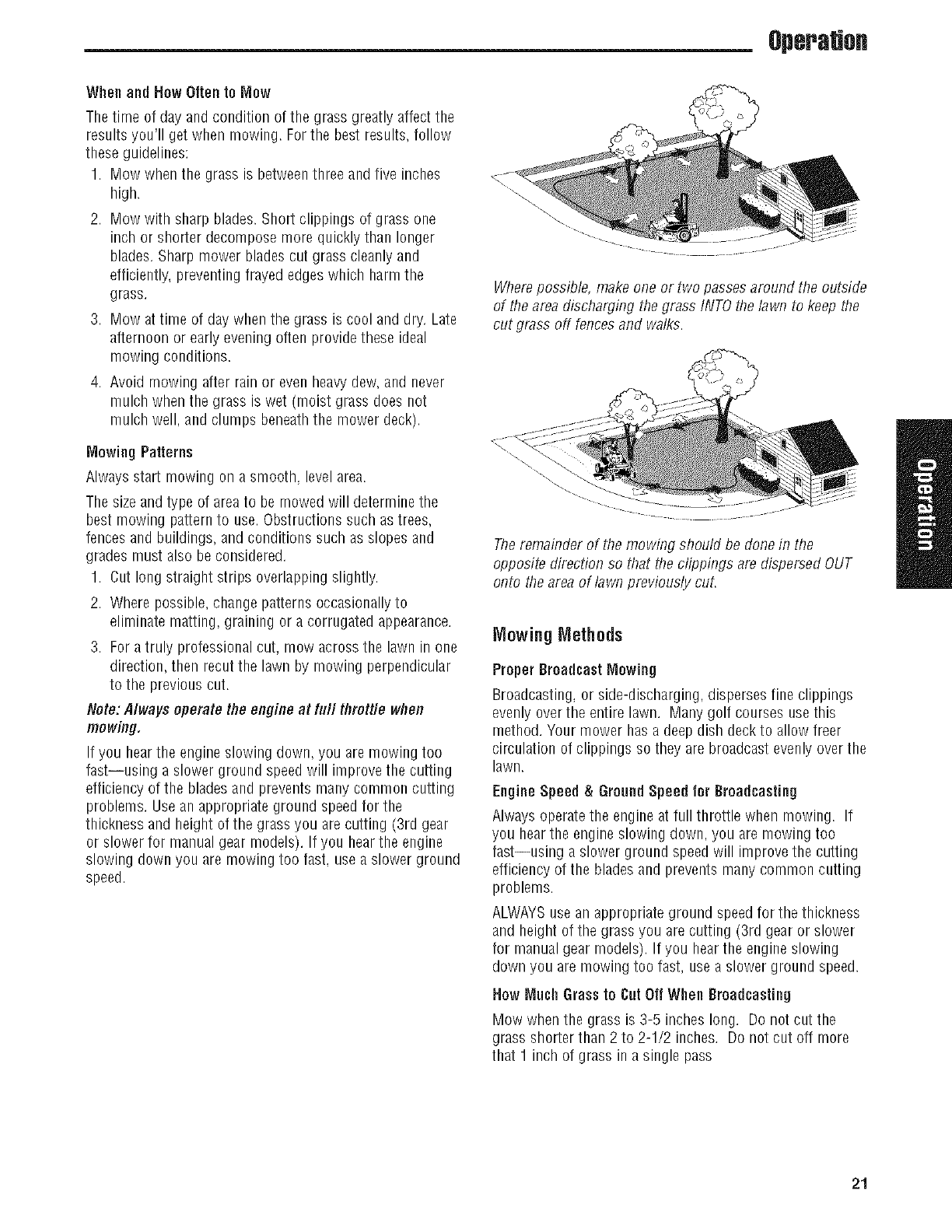
Wherepossible, make one or two passes around the outside
of the areadischarging the grass INTOthe lawn to keep the
cut grass off fences and walks.
The remainder of the mowing should be done in the
opposite direction so that the clippings are dispersed OUT
onto the areaof lawn previously cut.
Mowing Methods
ProperBroadcastMowing
Broadcasting, or side-discharging, disperses fine clippings
evenly overthe entire lawn. Many golf courses use this
method. Your mower has a deep dish deck to allow freer
circulation of clippings so they are broadcast evenlyover the
lawn.
Engine Speed & GroundSpeed for Broadcasting
Always operatethe engine atfull throttle when mowing. If
you hearthe engine slowing down, you are mowing too
fast--using a slower ground speed will improve the cutting
efficiency of the blades and prevents many common cutting
problems.
ALWAYSuse an appropriate ground speed for the thickness
and height of the grass you arecutting (3rd gear or slower
for manual gear models). If you hearthe engine slowing
down you are mowing too fast, use a slower ground speed.
How Much Grassto CotOff When Broadcasting
Mow when the grass is 3-5 inches long. Do not cut the
grass shorter than 2 to 2-1/2 inches. Do not cut off more
that 1 inch of grass in a single pass
21
Operation
ProperMulching
Mulching consists of a mower deck which cuts and recuts
clippings into tiny particles and which then blows them
down INTOthe lawn. Thesetiny particles decomposerapidly
into by-products your lawn can use. UNDERPROPER
CONDITIONS,your mulching mower will virtually eliminate
noticeable clippings on the lawn surface.
NOTE:When mulching under heavycutting conditions, a
rumbling sound may be presentand is normal.
Mulching RequiresEXCELLENTMowing Conditions
Mulching mowers cannot function properly if the grass is
wet, or if the grass is simply to high to cut, Evenmore than
normal mowing, mulching requires that the grass be dry
and the the appropriate amount is cut.
Do not use the mower as a mulching mower during the first
two or three mowings in the spring. The long grass blades,
quick growth, and often wetter conditions are more suitable
for broadcasting (side-discharging) or grass bagging
operation.
EngineSpeed & GroundSpeed for Mulching
Use full enginethrottle matched with a slow ground speed
so that clippings will befinely cut. Ground speed while
mulching should be HALFof the speed that would be used
when broadcasting (side discharging) under similar
conditions. Since mulching requires more horsepowerthan
broadcasting, using a slower ground speed is vitally
important for proper mulching operation.
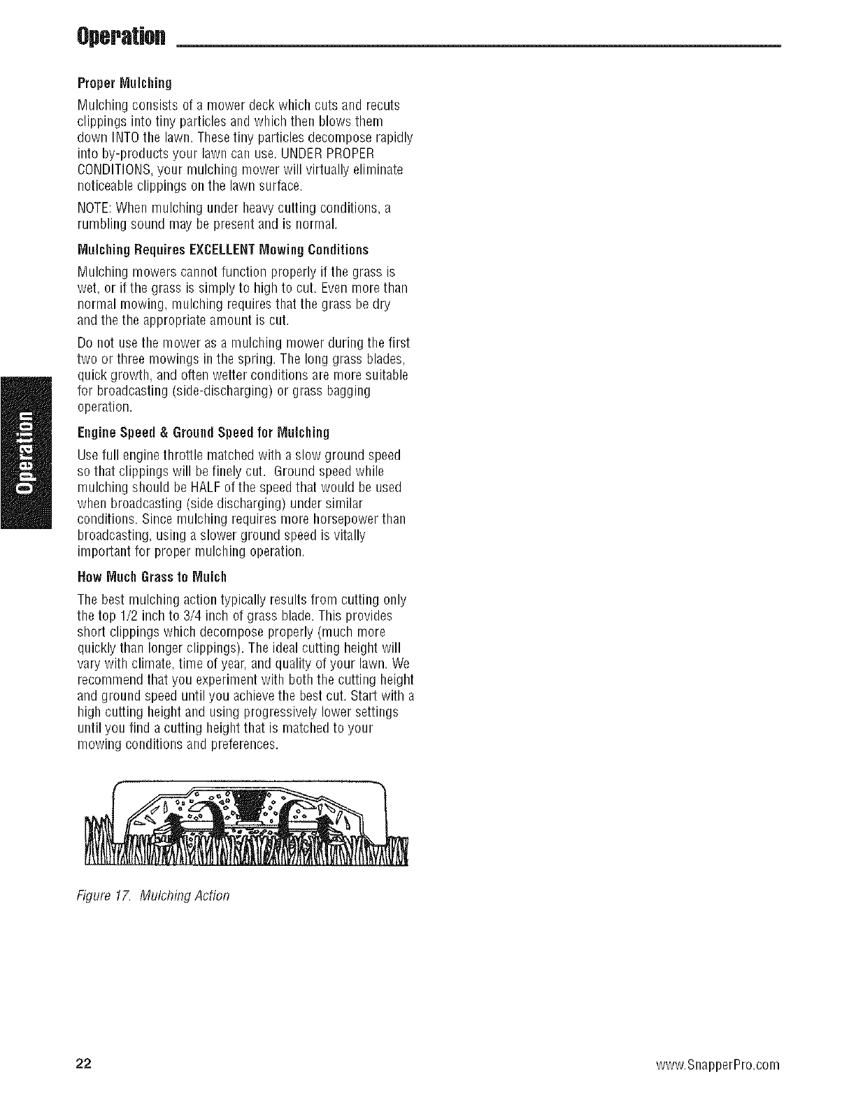
Now Much Grassto Mulch
The best mulching action typically results from cutting only
the top 1/2 inch to 3/4 inch of grass blade. This provides
short clippings which decompose properly (much more
quickly than longer clippings). The ideal cutting height will
vary with climate, time of year,and quality of your lawn. We
recommend that you experiment with both the cutting height
and ground speed until you achievethe best cut. Start with a
high cutting height and using progressively lower settings
until you find a cutting height that is matchedto your
mowing conditions and preferences.
Figure 17. Mulching Action
22 www.SnapperPro.com
RegularMaintenance
Regular Maintenance
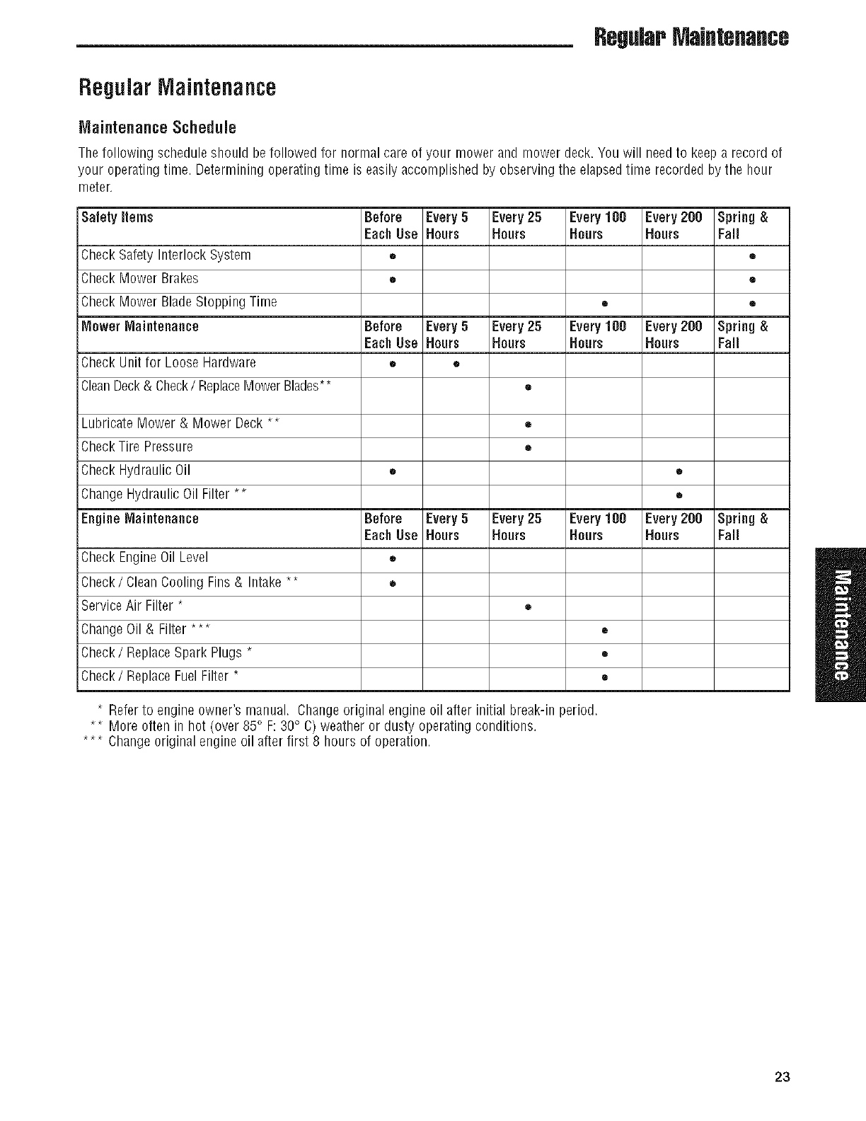
Maintenance Schedule
The following schedule should be followed for normal care of your mower and mower deck. Youwill needto keepa record of
your operating time. Determining operating time is easily accomplished by observing the elapsed time recorded by the hour
meter.
Safety items Before Every 5 Every25 Every100 Every200 Spring &
Each Use Hours Hours Hours Hours Fall
Check Safety Interlock System • •
Check Mower Brakes • •
i
iCheck Mower BladeStopping Time • •
Mower Maintenance Before Every 5 Every25 Every100 Every200 Spring &
Each Use Hours Hours Hours Hours Fall
Check Unit for Loose Hardware • •
CleanDeck& Check/ReplaceMowerBlades** •
Lubricate Mower & Mower Deck ** •
CheckTire Pressure •
Check Hydraulic Oil • •
Change Hydraulic Oil Filter ** •
EngineMaintenance Before Every 5 Every25 Every100 Every200 Spring &
Each Use Hours Hours Hours Hours Fall
i
iCt/eck EngineOil Level =
Check/Clean Cooling Fins& Intake ** •
ServiceAir Filter *•
jChangeOil & Filter *** •
Check/ReplaceSpark Plugs *•
Check/ReplaceFuel Filter *•
*Referto engine owner's manual. Changeoriginal engine oil after initial break-in period.
** More often in hot (over 85° F:30° C) weather or dusty operating conditions.
*** Changeoriginal engine oil after first 8 hours of operation.
23
RegularMaintenance
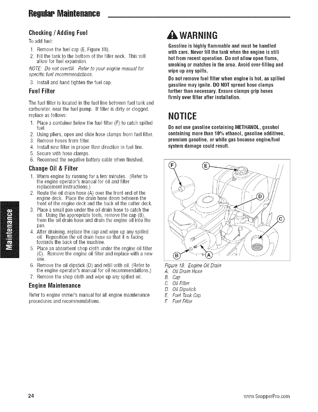
Checking/Adding Fuel
Toadd fuel:
1. Removethe fuel cap (E, Figure 18).
2. Fill the tankto the bottom of the filler neck. Thiswill
allow for fuel expansion.
NOTE. Do not overfill, Refer to your enginemanual for
specific fuel recommendations.
3. Install and handtighten the fuel cap.
Fuel Filter
The fuel filter is located in the fuel line betweenfuel tank and
carburetor, nearthe fuel pump. If filter is dirty or clogged,
replace as follows:
1. Placea container below the fuel filter (F) to catch spilled
fuel.
2. Using pliers, open and slide hose clamps from fuel filter.
3. Remove hosesfrom filter.
4. Install new filter in proper flow direction in fuel line.
5. Securewith hose clamps.
6. Reconnectthe negative battery cable when finished.
Change OiJ & FiJter
1. Warm engine by running for a few ndnutes. (Referto
the engineoperator's manual for oil and filter
replacement instructions.)
2. Routethe oil drain hose (A) over the front end of the
engine deck. Placethe drain hose down betweenthe
front of the enginedeck andthe back of the cutter deck.
3. Placea small pan under the oil drain hose to catch the
oil. Using the appropriate tools, removethe cap B,
from the oil drain hose and drain the engine o nto the
pan.
4. After draining, replacethe cap and wipe up any spilled
oil. Reposition the oil drain hose so that it is facing
towards the back of the machine.
5. Placean absorbent shop cloth underthe engine oil filter
(C). Removethe engine oil filter and replacewith a new
one.
6. Removethe oil dipstick (D) and refill with oil. (Refer to
the engineoperator's manual for oil recommendations.)
7. Removethe shop cloth and wipe up any spilled oil.
EngineMaintenance
Referto engineowner's manual for all engine maintenance
procedures and recommendations.
, WARNING
Gasolineis highly flammable and must be handled
with care. Never fill the tank when the engineis still
hot from recent operation. Do notallow open flame,
smokingor matchesin the area. Avoid over-fillingand
wipe up any spills.
Donotremove fuel filter when engineis hot, as spilled
gasoline may ignite. DONOTspreadhoseclamps
further than necessary.Ensureclampsgrip hoses
firmly ever filter after installation.
NOTICE
Donat use gasoline containingMETHANOL,gasohol
containingmore than 10% ethanol, gasoline additives,
premium gasoline, or white gas because engine/fuel
systemdamage couldresult.
Figure 18. Engine Oil Drain
A. Oil Drain Hose
B, Cap
C. Oil Filter
D. Oil Dipstick
EFuel TankCap
EFuel Filter
24 www.SnapperPro.com
RegularMaintenance
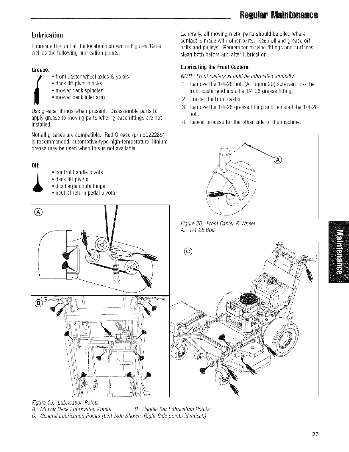
Lubrication
Lubricate the unit at the locationsshown in Figures19 as
well as the following lubricationpoints.
Grease:
f,.front caster wheel axles & yokes
,.deck lift pivot blocks
,.mower deck spindles
,.mower deck idler arm
Use greasefittings when present. Disassemble parts to
apply greaseto moving parts when grease fittings are not
installed.
Not all greases arecompatible. Red Grease(p/n 5022285)
is recommended,automotive-type high-temperature, lithium
grease may be used when this is not available.
Oil:
,.control handle pivots
,.deck lift pivots
,.discharge chute hinge
,.neutral return pedal pivots
Generally,all moving metal parts should be oiled where
contact is made with other parts. Keepoil and grease off
belts and pulleys. Rememberto wipe fittings and surfaces
clean both before and after lubrication.
Lubricatingthe Front Casters:
NOTE,Front casters should be lubricated annually.
1. Removethe 1/4-28 bolt (A, Figure 20) screwed into the
front caster and install a 1/4-28 grease fitting.
2. Greasethe front caster.
3. Removethe 1/4-28 grease fitting and reinstall the 1/4-28
bolt.
4. Repeatprocess for the other side of the machine.
Figure 20. Front Caster & Wheel
A. 1/4-28 Bolt
©
Figure 19, Lubrication Points
A, Mower Deck Lubrication Points B. Handle Bar Lubrication Points
C. GeneralLubrication Points (Left Side Shown, Right Sidepoints identical.)
25
RegularMaintenance
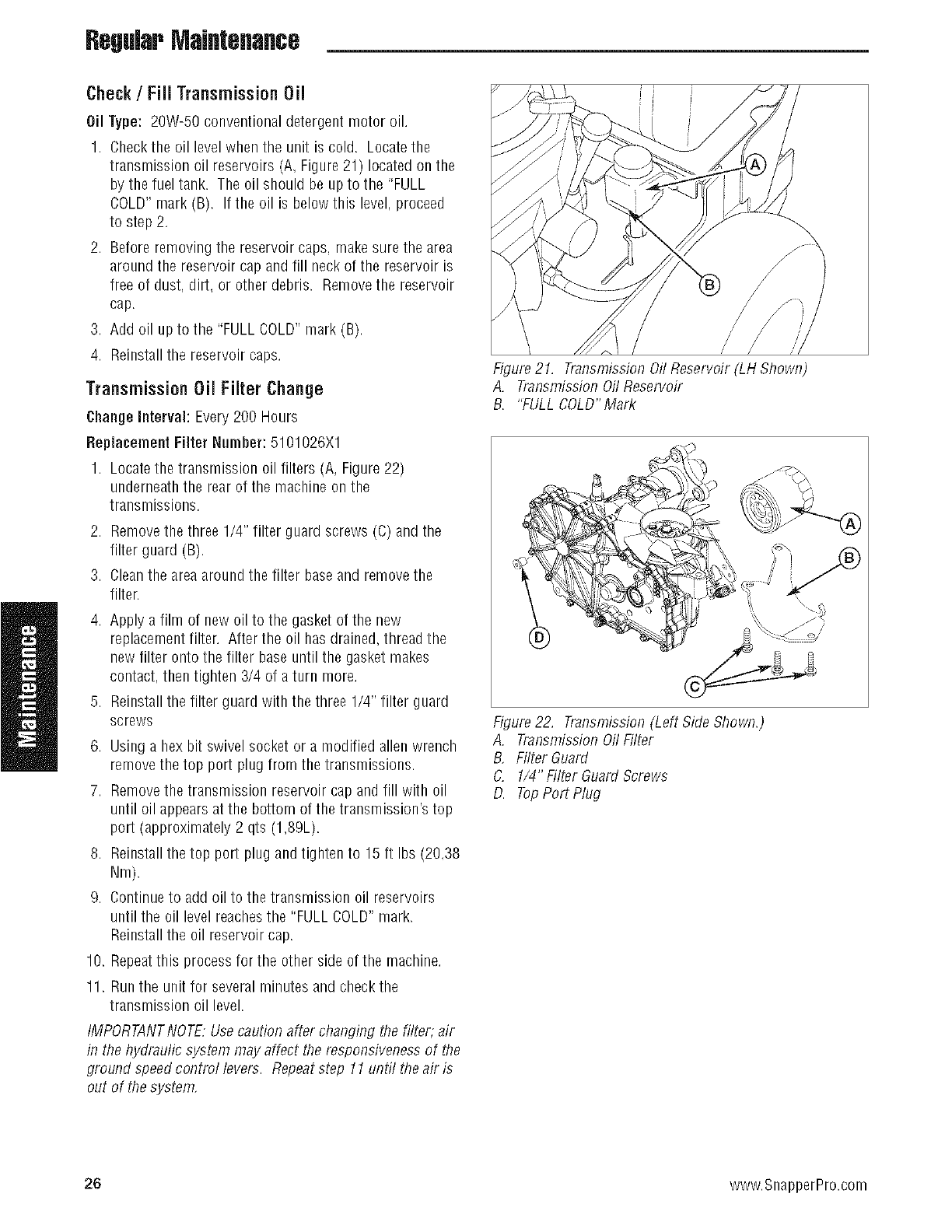
Check/Fiii Transmission Oil
Oil Type: 20W-50 conventional detergent motor oil.
1. Checkthe oil levelwhen the unit is cold. Locatethe
transmissionoil reservoirs (A, Figure 21) locatedon the
by the fuel tank. The oil should be up to the 'FULL
COLD"mark (B). If the oil is below this level, proceed
to step 2.
2. Before removing the reservoir caps, makesure the area
around the reservoir cap andfill neck of the reservoir is
free of dust. dirt. or other debris. Removethe reservoir
cap.
3. Add oil up to the "FULL COLD"mark (B).
4. Reinstall the reservoir caps.
TransmissionOil Filter Change
ChangeInterval: Every200 Hours
Replacement Filter Number: 5101026X1
1. Locatethe transmission oil filters (A, Figure22)
underneaththe rear of the machine on the
transmissions.
2. Removethe three 1/4" filter guard screws (C) and the
filter guard (B).
3. Cleanthe areaaround the filter baseand removethe
filter.
4. Apply a film of new oil to the gasket of the new
replacementfilter. After the oil has drained, thread the
new filter onto the filter base until the gasket makes
contact, then tighten 3/4 of aturn more.
5. Reinstall the filter guard with the three 1/4" filter guard
screws
6. Using a hex bit swivel socket or a modified allenwrench
removethe top port plug from the transmissions.
7. Removethe transmission reservoir cap and fill with oil
until oil appearsat the bottom of the transmission's top
port (approximately 2 qts (1,89L).
8. Reinstall the top port plug and tighten to 15ft Ibs (20.38
Nm).
9. Continueto add oil to the transmission oil reservoirs
until the oil level reachesthe "FULL COLD"mark.
Reinstall the oil reservoir cap.
10. Repeatthis process for the other side of the machine.
11. Run the unit for several minutes and check the
transmission oil level.
IMPORTANTNOTE:Use caution after changing the filter, air
in the hydraulic system may affect the responsiveness of the
ground speed control levers. Repeatstep 11until the air is
out of the system,
Figure 21. Transmission Oil Reservoir (LH Shown)
A. Transmission Oil Reservoir
B. "FULL COLD"Mark
Figure 22. Transmission (Left Side Shown.)
A. Transmission Oil Filter
B, Filter Guard
C. 1/4" Filter Guard Screws
D. TopPort Plug
26 www.SnapperPro.com
RegularMaintenance
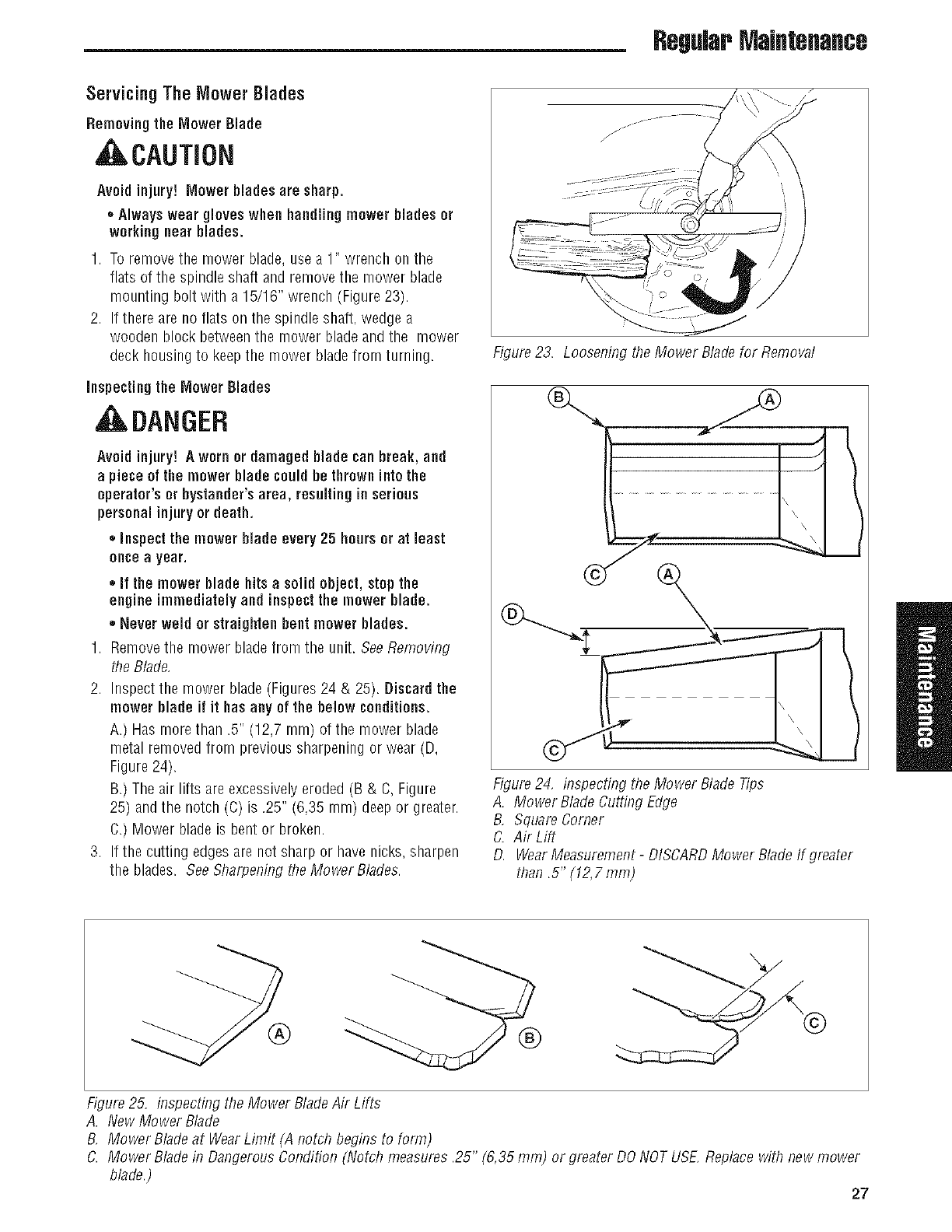
Servicing The Mower Blades
Removing the Mower Blade
, ,CAUTION
Avoid injury! Mower blades are sharp.
*Always wear gloves when handling mower blades or
working near blades.
1. To removethe mower blade, use a 1" wrench on the
flats of the spindle shaft and remove the mower blade
mounting bolt with a 15/16" wrench (Figure 23).
2. If there are no flats on the spindle shaft, wedge a
wooden block betweenthe mower bladeand the mower
deck housing to keepthe mower bladefrom turning.
inspecting the Mower Blades
, ILDANGER
Avoid injury! A worn or damaged blade can break, and
a piece of the mower blade couldbe thrown into the
operator's or bystander's area, resulting in serious
personal injury or death.
,, inspect the mower blade every 25 hours or at least
onceayear.
,,if the mower blade hitsa solid object, stop the
engine immediatelyand inspectthe mower blade.
,, Never weld or straighten bent mower blades.
1. Removethe mower bladefrom the unit. BeeRemoving
the Blade,
2. Inspect the mower blade (Figures 24 & 25). Discardthe
mower blade if it hasany of the below conditions.
A.) Has more than .5" (12,7 mm) of the mower blade
metal removed from previous sharpening or wear (D,
Figure 24).
B.) The air lifts are excessivelyeroded (B & C, Figure
25) andthe notch (C) is .25" (6,35 mm) deep or greater.
C.) Mower blade is bent or broken.
3. If the cutting edges are not sharp or have nicks, sharpen
the blades. See Sharpening the Mower Blades.
Figure 23. Loosening the Mower Bladefor Removal
\
Figure 24, inspecting the Mower Blade Tips
A. Mower BladeCutting Edge
B, Square Comer
C. Air Lift
D. WearMeasurement- DISCARDMower Bladelf greater
than .5" (12,7 ram)
®
Figure25. inspecting the Mower BladeAir Lifts
A. New Mower Blade
B, Mower Bladeat WearLimit (A notch begins to form)
C. Mower Bladein Dangerous Condition (Notch measures .25" (6,35 ram) or greater DO NOTUSE,Replacewith new mower
blade.) 27
RegularMaintenance
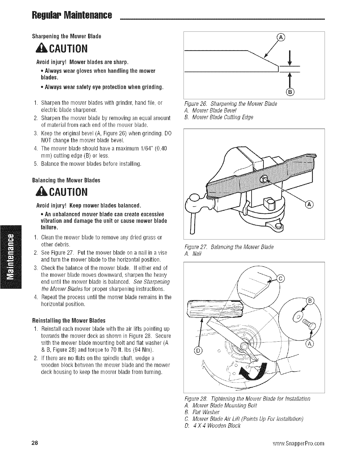
Sharpening the Mower Blade
, CAUTION
Avoid injury! Mower blades are sharp.
,, Alwayswear gloves when handling the mower
blades.
,, Alwayswear safety eye protectionwhen grinding.
1. Sharpenthe mower blades with grinder, handfile. or
electric blade sharpener.
2. Sharpenthe mower blade by removing an equal amount
of material from each end of the mower blade.
3. Keepthe original bevel (A, Figure26) when grinding. DO
NOTchangethe mower blade bevel.
4. The mower bladeshould have a maximum 1/64" (0,40
ram) cutting edge (B) or less.
5. Balancethe mower blades before installing.
Balancing the ['/lowerBlades
, CAUTION
Avoidinjury! Keepmower blades balanced.
• An unbalanced mower blade can create excessive
vibrationand damage the unit or cause mower blade
failure.
1. Cleanthe mower bladeto remove any dried grass or
other debris.
2. SeeFigure 27. Put the mower blade on a nail in a vise
and turn the mower bladeto the horizontal position.
3. Checkthe balanceof the mower blade. If either end of
the mower blade moves downward, sharpen the heavy
end until the mower blade is balanced. SeeSharpening
the Mower Blades for proper sharpening instructions.
4. Repeatthe process until the mower blade remains in the
horizontal position.
Reinstallingthe ['/lowerBlades
1. Reinstall each mower bladewith the air lifts pointing up
towards the mower deck as shown in Figure 28. Secure
with the mower blade mounting bolt and flat washer (A
& B, Figure 28) and torque to 70 ft. Ibs (94 Nm).
2. If there are no flats on the spindle shaft, wedge a
wooden block betweenthe mower bladeand the mower
deck housing to keepthe mower bladefrom turning.
t
®
Figure 26, Sharpening the Mower Blade
A. Mower BladeBevel
B. Mower BladeCutting Edge
Figure 27. Balancing the Mower Blade
A. Nail
Figure 28, Tighteningthe Mower Blade for Installation
A. Mower Blade Mounting Bolt
B, Flat Washer
C. Mower BladeAir Lift (Points Up For Installation)
D. 4X4 WoodenBlock
28 www.SnapperPro.com
RegularMaintenance
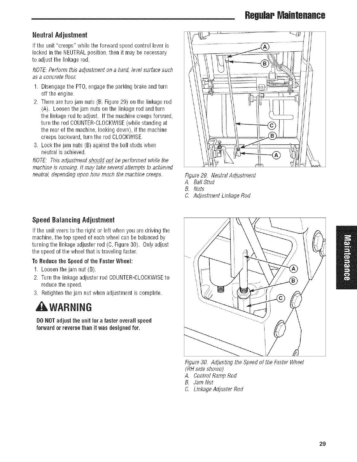
Nentral Adjustment
Iftheunit"creeps"wHlethe forwardspeedcontrolleveris
lockedinthe NEUTRALposition,thenit maybenecessary
to adjustthe linkagerod.
NOTE:Perform this adjustment on a hard, level surface such
as a concrete floon
1. Disengagethe PTO,engagethe parking brake and turn
off the engine.
2. There are two jam nuts (B, Figure 29) on the linkage rod
(A). Loosen the jam nuts on the linkage rod and turn
the linkage rod to adjust. If the machine creepsforward,
turn the rod COUNTER-CLOCKWISE(while standing at
the rear of the machine, looking down), if the machine
creeps backward,turn the rod CLOCKWISE.
3. Lock the jam nuts (B) against the ball studs when
neutral is achieved.
NOTE: This adjustment should not be performed while the
machine is running, It may take severalattempts to achieved
neutral, depending upon how much the machine creeps. Figure29. Neutral Adjustment
A. Ball Stud
B, Nuts
C. Adjustment Linkage Rod
Speed Balancing Adjnstment
If the unit veersto the right or left when you aredriving the
machine, the top speed of each wheel can be balanced by
turning the linkage adjuster rod (C, Figure 30). Only adjust
the speed of the wheel that is traveling faster,
ToReducethe Speed of the FasterWheel:
1. Loosen the jam nut (B).
2. Turn the linkage adjuster rod COUNTER-CLOCKWISEto
reduce the speed.
3. Retighten the jam nut when adjustment is complete.
, WARNING
DONOTadjust the unit for a faster overall speed
forward or reverse thanit was designed for.
Figure 30, Adjusting the Speedof the Faster Wheel
(RHside shown)
A. Contml Ramp Rod
B, Jam Nut
C. Linkage Adjuster Rod
29

RegularMaintenance
ParkingBrakeAdjustment
1. Disengagethe PTO,stup the engine, removethe ignitiun
key,and engagethe parking brake.
2. Locatethe brake spring (A, Figure31) underneath the
rear of the machine.
3. With the parking brake engaged, measurethe
compressed spring length of the brake spring. The
spring should be 2-3/8" (6,03 cm) when compressed.
If not, position the lock nut until the measurement
equals 2-3/8" (6,03 cm).
4. Measurethe distance betweenthe back of the brake
pivot link (G) and the front edge of the set collar (F).
The measurementshould be 1/8" (0,32 cm). If not,
position the set collar until the measurementequals 1/8"
(0,32 cm).
if this dues notcorrectthe braking problem, seeyuur
Snapper Prudealer.
Figure 31. Parking Brake Adjustment
A. Brake Spring
B, First Measurement -.2-3/8" (6,03 cm)
C. Brake Spring Rod
D. LockNut
E, Second Measurement -1/8" (0,32 cm)
F. Set Collar
G, Brake Pivot Link
30 www.SnapperPro.com
RegWr MaJflteflaflce
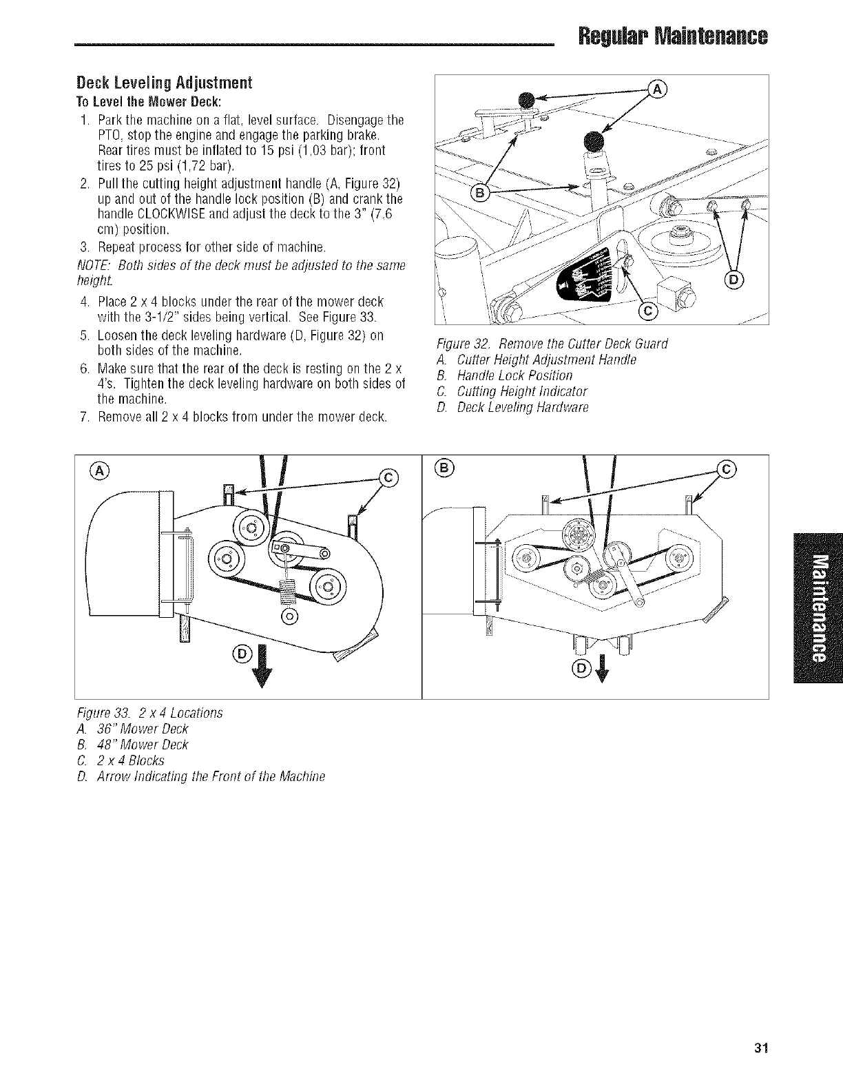
Deck Leveling Adjustment
ToLeveltheMowerDeck:
1. Park the machine on a flat. level surface. Disengagethe
PTO,stop the engine and engagethe parking brake.
Reartires must be inflated to 15 psi (1,03 bar); front
tires to 25 psi (1,72 bar).
2. Pull the cutting height adjustment handle (A, Figure 32)
up and out of the handle lock position (B) and crank the
handle CLOCKWISEand adjust the deck to the 3" (7,6
cm) position.
3. Repeatprocess for other side of machine.
NOTE: Both sides of the deckmust be adjusted to the same
heighL
4. Place2 x 4 blocks under the rear of the mower deck
with the 3-1/2" sides being vertical. SeeFigure 33.
5. Loosen the deck leveling hardware(D, Figure 32) on
both sides of the machine.
6. Makesure that the rear of the deck is resting onthe 2 x
4's. Tightenthe deck leveling hardware on both sides of
the machine.
7. Removeall 2 x 4 blocks from under the mower deck.
Figure 3! Remove the Cutter Deck Guard
A. Cutter Height Adjusflnent Handle
B, Handle Lock Position
C. Cutting Height Indicator
D. Deck Leveling Hardware
®®
Figure 33. 2 x4 Locations
A. 36"Mower Deck
B, 48" Mower Deck
C. 2 x 4 Blocks
D. Arrow Indicating the Front of the Machine
31
RegWr Maintenance
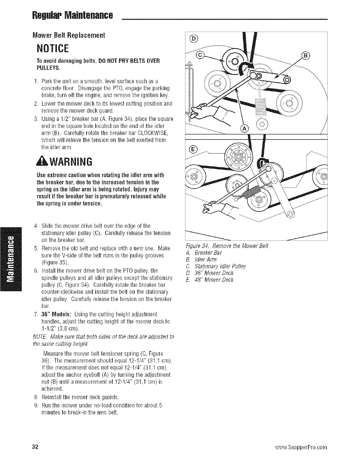
Mower Belt Replacement
NOTICE
Toavoid dan]agingbelts, DONOTPRY BELTSOVER
PULLEYS.
1. Park the unit on a smooth, level surface such as a
concrete floor. Disengagethe PTO,engagethe parking
brake,turn off the engine, and removethe ignition key.
2. Lower the mower deck to its lowest cutting position and
removethe mower deck guard.
3. Using a 1/2" breaker bar (A, Figure 34), placethe square
end in the square hole locatedon the end of the idler
arm (B). Carefully rotate the breaker bar CLOCKWISE,
which will relieve the tension on the belt exerted from
the idler arm.
,tI&WARNING
Use extremecautionwhen rotatingthe idler arm with
the breaker bar, due to the increasedtensionin the
springas the idler arm is beingrotated, injury may
result if the breaker bar is prematurelyreleasedwhile
the spring is under tension.
4. Slidethe mower drive belt over the edge of the
stationary idler pulley (C). Carefully releasethe tension
on the breaker bar.
5. Removethe old belt and replace with a new one. Make
sure the V-side of the belt runs in the pulley grooves
(Figure 35).
6. Install the mower drive belt on the PTOpulley,the
spindle pulleys and all idler pulleys except the stationary
pulley (C, Figure34). Carefully rotate the breaker bar
counter-clockwise and install the belt on the stationary
idler pulley. Carefully releasethe tension on the breaker
bar.
7. 36" Models: Using the cutting height adjustment
handles,adjust the cutting height of the mower deckto
1-1/2" (3,8 cm).
NOTE: Make sure that both sides of the deckare adjusted to
the same cutting heighL
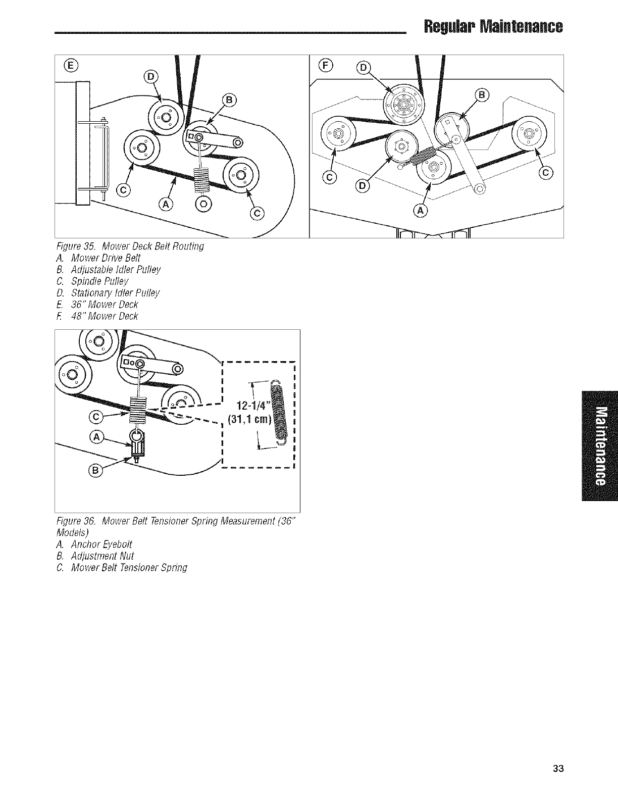
Measurethe mower belt tensioner spring (C, Figure
36). The measurementshould equal 12-1/4" (31,1 cm).
If the measurementdoes not equal 12-1/4" (31,1 cm),
adjust the anchor eyebolt (A) by turning the adjustment
nut (B) until a measurement of 12-1/4" (31,1 cm) is
achieved.
8. Reinstall the mower deck guards.
9. Run the mower under no-load condition for about 5
minutes to break-in the new belt.
®
Figure 34. Remove the Mower Belt
A. Breaker Bar
B, Idler Arm
C. Stationary Idler Pulley
D. 36" Mower Deck
f48"Mower Deck
32 www.SnapperPro.com
RegWr MsJflteflsflce
® ®
Figure 35, Mower Deck Belt Routing
A. Mower Drive Belt
B, Adjustable Idler Pulley
C. Spindle Pulley
D. Stationary Idler Pulley
E, 36" Mower Deck
£ 48"Mower Deck
Figure 36, Mower Belt TensionerSpring Measurement (36"
Models)
A. Anchor Eyebolt
B, Adjustment Nut
C. Mower Belt TensionerSpring
33
RegularMaintenance
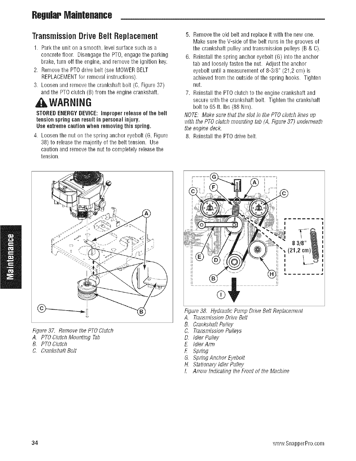
TransmissionDriveBelt Replacement
1. Park the unit on a smooth, level surface such as a
concrete floor. Disengagethe PTO,engagethe parking
brake,turn off the engine, and remove the ignition key.
2. Removethe PTOdrive belt (see MOWERBELT
REPLACEMENTfor removal instructions).
3. Loosen and removethe crankshaft bolt (C, Figure37)
and the PTOclutch (B) from the engine crankshaft.
WARNING
STOREDENERGYDEVICE: improperrelease of the belt
tension springcan resultin personalinjury.
Use extreme cautionwhen removingthis spring.
4. Loosen the nut on the spring anchor eyebolt (G, Figure
38) to releasethe majority of the belt tension. Use
caution and removethe nut to completely releasethe
tension.
5. Removethe old belt and replace it with the new one.
Makesure the V-side of the belt runs in the grooves of
the crankshaft pulley and transmission pulleys (B & C).
6. Reinstall the spring anchor eyebolt (G) into the anchor
tab and loosely fasten the nut. Adjust the anchor
eyebolt until a measurement of 8-3/8" (21,2 cm) is
achieved from the outside of the spring hooks. Tighten
nut.
7. Reinstall the PTOclutch to the engine crankshaft and
secure with the crankshaft bolt. Tighten the crankshaft
bolt to 65 ft. Ibs (88 Nm).
NOTE. Make sure that the slot in the PTOclutch lines up
with ftle PTOclutch mounting tab (A, Figure 37) undemeaB1
the engine deck.
8. Reinstall the PTOdrive belt.
Figure 37. Remove the PTOClutch
A. PTO Clutch Mounting Tab
B, PTO Clutch
C. Crankshaft Bolt
......................................................
Figure 38. Hydraulic Pump Drive Belt Replacement
A. Transmission Drive Belt
B, Crankshaft Pulley
C. Transmission Pulleys
D. Idler Pulley
EIdlerArm
E Spring
G, Spring Anchor Eyebolt
H, Stationary Idler Pulley
I. Arrow Indicating the Front of the Machine
34 www.SnapperPro.com
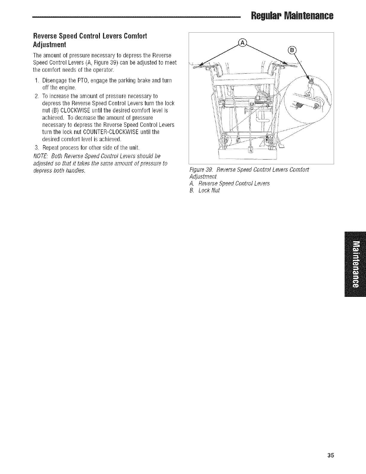
RegWr Maintenance
ReverseSpeed Control LeversComfort
Adjustment
The amount of pressure necessaryto depress the Reverse
SpeedControl Levers (A, Figure 39) can be adjustedto meet
the comfort needs of the operator.
1. Disengagethe PTO,engagethe parking brake and turn
off the engine.
2. To increasethe amount of pressure necessaryto
depress the ReverseSpeedControl Leversturn the lock
nut (B) CLOCKWISEuntil the desired comfort level is
achieved. To decreasethe amount of pressure
necessaryto depress the ReverseSpeedControl Levers
turn the lock nut COUNTER-CLOCKWISEuntil the
desired comfort level is achieved.
3. Repeatprocess for other side of the unit.
NOTE. Both ReverseSpeedControl Leversshould be
adjusted so that it takes the same amount of pressure to
depressboth handles. Figure 39, ReverseSpeedControl Levers Comfort
AdjusflrTent
A. Reverse SpeedControl Levers
B. Lock Nut
35
RegWr MaJflteflaflce
Storage
TemporaryStorage (38 DaysOr Less)
Remember,the fuel tank will still contain some gasoline, so
never store the unit indoors or in any other area where fuel
vapor could travel to any ignition source. Fuel vapor is also
toxic if inhaled, so neverstore the unit in any structure used
for human or animal habitation.
Here is a checklist of things to do when storing your unit
temporarily or in between uses:
,, Keepthe unit in an area away from where children may
come into contact with it. If there's any chanceof
unauthorized use, removethe spark plug (s) and put in a
safe place.Be sure the spark plug opening is protected
from foreign objects with a suitable cover.
,, If the unit can't be stored on a reasonable level surface.
chockthe wheels.
,, Cleanall grass and dirt from the mower.
LongTermStorage (Longer Than 30 Days)
Before you store your unit for the off-season, read the
Maintenance and Storage instructions in the Safety Rules
section, then perform the following steps:
1. Drain crankcase oil while engine is hot and refill with a
grade of oil that will be required when unit is used again.
2. Preparethe mower deckfor storage as follows:
a. Removemowerdeckfrom the unit.
b. Cleanundersideof mowerdeck.
c. Coatall baremetalsurfaceswith paint or light coat of
oil to preventrusting.
3. Cleanexternal surfaces and engine.
4. Prepareenginefor storage. Seeengine owner's
manual.
5. Cleanany dirt or grass from cylinder headcooling fins.
engine housing and air cleaner element.
6. Coverair cleaner and exhaust outlet tightly with plastic
or other waterproof material to keep out moisture, dirt
and insects.
7. Completelygrease and oil unit as outlined in the Normal
Caresection.
8. Cleanup unit andapply paint or rust preventativeto any
areas where paint is chipped or damaged.
9. Besure the battery is filled to the proper level with water
and is fully charged. Battery life will be increased if it is
removed, put in a cool, dry place and fully charged
about once a month. If battery is left in unit, disconnect
the negativecable.
AWARNING
Neverstore the unit, with gasoline in engineor fuel
tank, in a heated shelter or in enclosed, poorly
ventilatedenclosures. Gasolinefumes may reach an
openflame, sparkor pilot light (such as a furnace,
water heater, clothesdryer, etc.) and causean
explosion.
Handle gasoline carefully. Dis highly flammable and
carelessuse couldresult in seriousfire damage to
your person or property.
Drain fuel into an approved containeroutdoorsaway
fram open flame or sparks.
10. Drain fuel system completely or add a gasoline stabilizer
to the fuel system. If you havechosen to use afuel
stabilizer and have not drained the fuel system, follow all
safety instructions and storage precautions in this
manual to prevent the possibility of fire from the ignition
of gasoline fumes. Remember,gasoline fumes can travel
to distant sources of ignition and ignite, causing risk of
explosion and fire.
NOTE.Gasoline,if permitted to stand unused for extended
periods (30 days or more), may developgummy deposits
which can adversely affect the engine carburetor and cause
enginemalfunction. Toavoid this condition, add a gasoline
stabilizer to the fuel tank and run the enginea few minutes,
or drain all fuel from the unit before placing it in storage.
Starting After Long Term Storage
Beforestartingtheunit afterit hasbeenstoredfor along
periodof time, performthefollowingsteps.
1. Removeany blocks from under the unit.
2. Install the battery if it was removed.
3. Unplug the exhaust outlet and air cleaner.
4. Fill the fuel tank with fresh gasoline. Seeengine
manual for recommendations.
5. Seeengine owner's manual and follow all instructions
for preparing engine after storage.
6. Checkcrankcase oil level and add proper oil if
necessary.If any condensation has developedduring
storage, drain crankcaseoil and refill.
7. Inflate tires to proper pressure. Checkfluid levels.
8. Start the engine and letit run slowly. DO NOTrun at
high speed immediately after starting. Besure to run
engine only outdoors or in well ventilated area.
36 www.SnapperPro.com
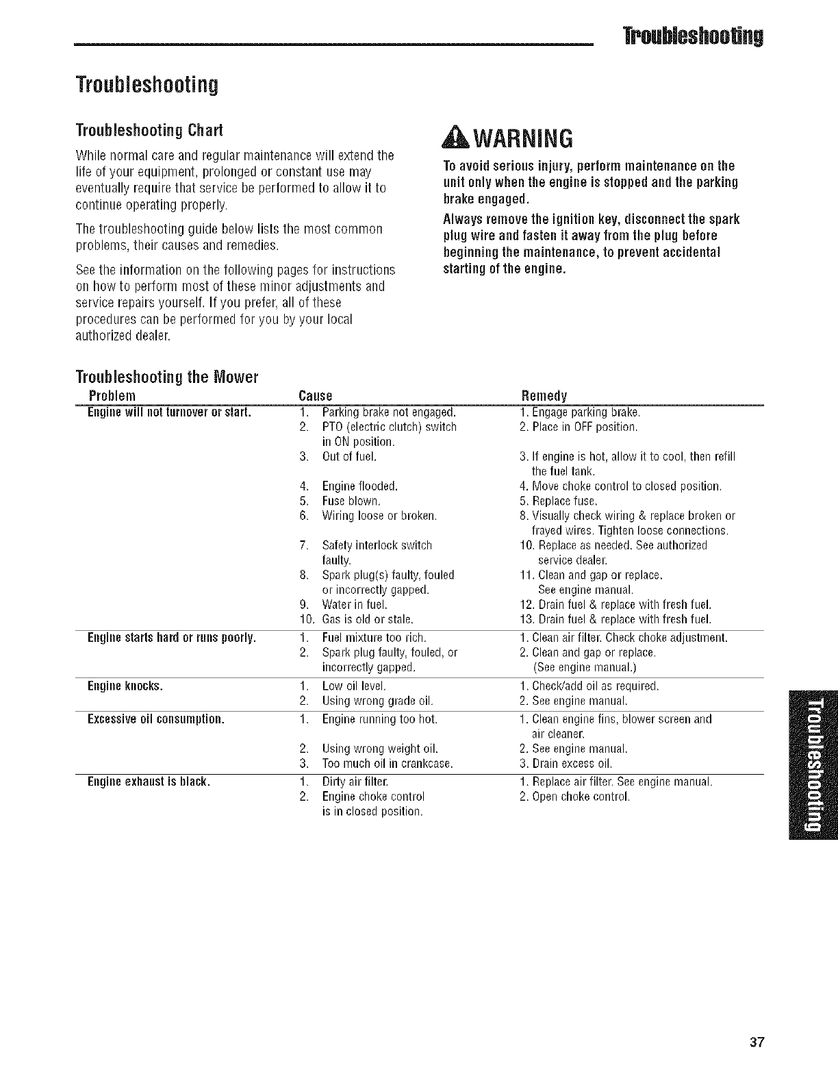
Troubleshooting
Troubleshooting
TroubleshootingChart
While normal care and regular maintenancewill extend the
life of your equipment, prolonged or constant use may
eventually require that service be performed to allow it to
continue operating properly.
The troubleshooting guide below lists the most common
problems, their causes and remedies.
Seethe information on the following pages for instructions
on how to perform most of these minor adjustments and
service repairs yourself. If you prefer, all of these
procedures can be performed for you by your local
authorized dealer.
AWARNING
Toavoid seriousinjury, performmaintenance onthe
unit onlywhenthe engine is stoppedand the parking
brake engaged.
Always removethe ignition key, disconnect the spark
plug wire and fasten it away from the plug before
beginning the maintenance, to prevent accidental
startingof the engine.
Troubleshooting the Mower
Problem
Engine will not turnoveror start.
Cause
1. Parking brake not engaged.
2. PTO (electric clutch) switch
in ON position.
3. Out of fuel.
4. Engineflooded.
5. Fuseblown.
6. Wiring loose or broken.
7. Safety interlock switch
faulty.
8. Spark plug(s) faulty, fouled
or incorrectly gapped.
9. Water in fuel.
10. Gas is old or stale.
Engine startshard or rune poorly. 1. Fuel mixture too rich.
2. Spark plug faulty, fouled, or
incorrectly gapped.
Engine knocks. 1. Low oil level.
2. Using wrong grade oil.
Excessive oil consumption. 1. Engine running too hot.
2. Using wrong weight oil.
3. Toomuch oil in crankcase.
Engine exhanst is black. 1. Dirty air filter.
2. Engine choke control
is in closed position.
Remedy
1. Engage parking brake.
2. Placein OFFposition.
3. If engineis hot, allow it to cool, then refill
the fuel tank.
4. Move choke control to closed position.
5. Replacefuse.
8. Visually check wiring & replace broken or
frayed wires. Tighten loose connections.
10. Replaceas needed.Seeauthorized
service dealer.
11. Cleanand gap or replace.
Seeengine nlanual.
12. Drain fuel & replace with fresh fuel.
13. Drain fuel & replace with fresh fuel.
1. Clean air filter. Check choke adjustment.
2. Clean and gap or replace.
(Seeengine nlanual.)
1. Check/add oil as required.
2. See engine nlanual.
1. Clean engine fins, blower screen and
air cleaner.
2. See engine nlanual.
3. Drain excessoil.
1. Replaceair filter. See engine manual.
2. Open choke control.
37
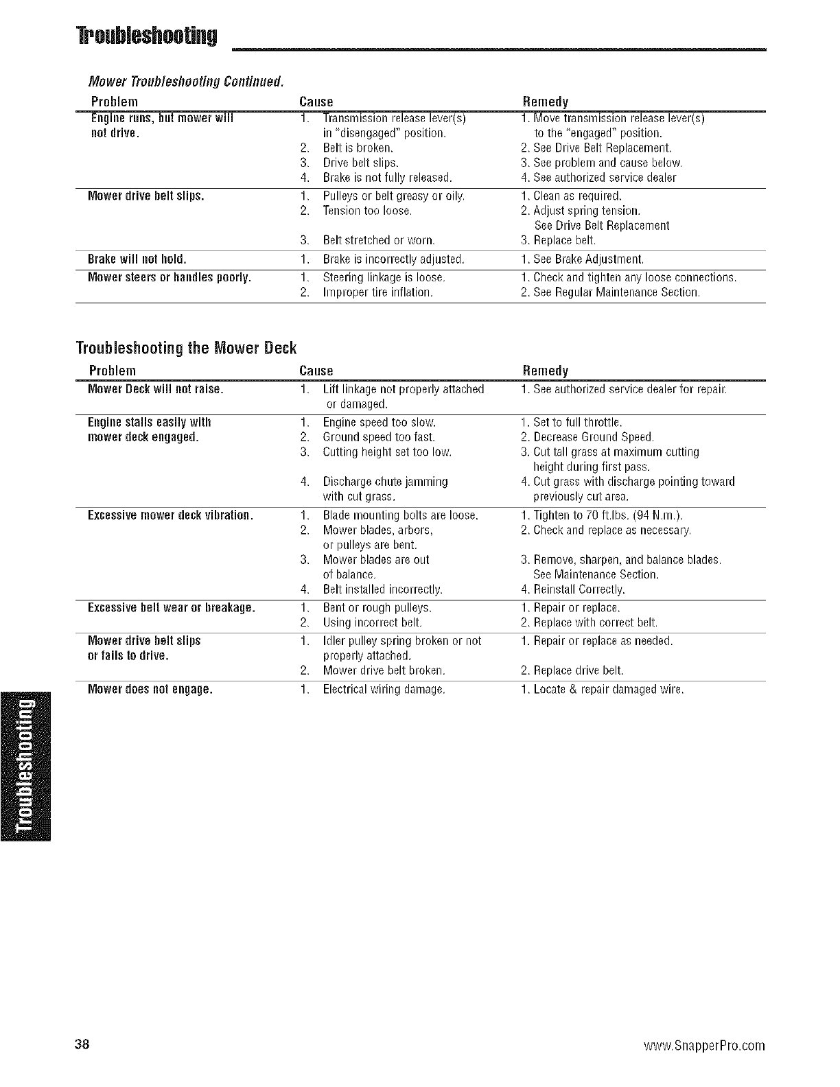
Troubleshootiflg
Mower Trouh/eshppting Continued,
Problem Cause Remedy
Eegille rues, but mower will 1. Transmission releaselever(s) 1. Move transmissionreleaselever(s)
not drive, in "disengaged" position, to the "engaged" position.
2. Belt is broken. 2. See Drive Belt Replacement.
3. Drive belt slips. 3. See problem and cause below.
4. Brake is not fully released. 4. Seeauthorized service dealer
Mower drive belt slips. 1. Pulleys or belt greasy or oily. 1. Clean as required.
2. Tensiontoo loose. 2. Adjust spring tension.
See Drive Belt Replacement
3. Belt stretched or worn. 3. Replacebelt.
Brake wiil not bold. 1. Brake is incorrectly adjusted. 1. See BrakeAdjustment.
Mower steers or bandies poorly. 1. Steering linkage is loose. 1. Check and tighten any loose connections.
2. Improper tire inflation. 2. See Regular Maintenance Section.
Troubleshooting the Mower Deck
Problem Cause Remedy
Mower Deck will not raise. 1. Lift linkage not properly attached 1. Seeauthorized service dealerfor repair.
or damaged.
Engine stalls easily witb 1. Engine speedtoo slow. 1. Set to full throttle.
inower deck engaged. 2. Ground speedtoo fast. 2. DecreaseGround Speed.
3. Cutting height set too low. 3. Cut tall grass at maximum cutting
height during first pass.
4. Discharge chute jamming 4. Cut grass with discharge pointing toward
with cut grass, previously cut area.
Excessive mower deck vibraDon. 1. Blade mounting bolts are loose. 1. Tighten to 70 ft.lbs. (94 N.m.).
2. Mower blades, arbors, 2. Check and replaceas necessary.
or pulleys are bent.
3. Mower blades are out 3. Remove,sharpen, and balanceblades.
of balance. SeeMaintenance Section.
4. Belt installed incorrectly. 4. Reinstall Correctly.
Excessive belt wear or breakage. 1. Bent or rough pulleys. 1. Repair or replace.
2. Using incorrect belt. 2. Replacewith correct belt.
Mower drive belt slips 1. Idler pulley spring broken or not 1. Repair or replaceas needed.
orfails to drive, properly attached.
2. Mower drive belt broken. 2. Replacedrive belt.
Mower does not engage. 1. Electrical wiring damage. 1. Locate& repair damagedwire.
38 www.SnapperPro.com
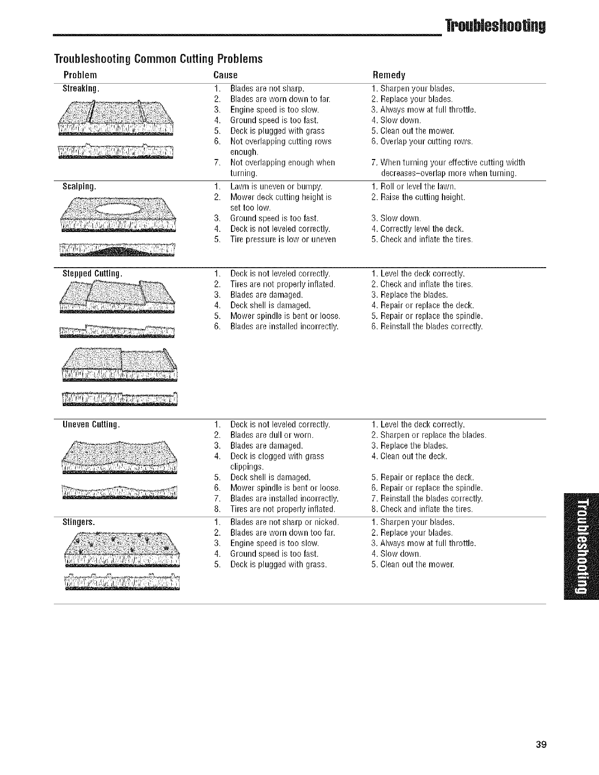
Troubleshootiflg
TroubleshootingCommonCutting Problems
Problem Cause
Streaking.
Scalphlg.
1. Blades are not sharp.
2. Blades are worn down to far.
3. Engine speedis too slow.
4. Ground speed is too fast.
5. Deck is plugged with grass
6. Not overlapping cutting rows
enough.
7. Not overlapping enough when
turning.
1. Lawn is uneven or bumpy.
2. Mower deck cutting height is
set too low.
3. Ground speed is too fast.
4. Deck is not leveled correctly.
5. Tire pressure is low or uneven
Remedy
1. Sharpen your blades.
2. Replaceyour blades.
3. Always mow at full throttle.
4. Slow down.
5. Clean out the mower.
6. Overlapyour cutting rows.
7. When turning your effective cutting width
decreases-overlap more when turning.
1. Roll or level the lawn.
2. Raisethe cutting height.
3. Slow down.
4. Correctly level the deck.
5. Check and inflate the tires.
Stepped c[Inhlg. 1. Deck is not leveled correctly. 1. Levelthe deck correctly.
2. Tires are not properly inflated. 2. Check and inflate the tires.
3. Blades are damaged. 3. Replacethe blades.
4. Deck shell is damaged. 4. Repair or replacethe deck.
5. Mower spindle is bent or loose. 5. Repair or replacethe spindle.
6. Blades are installed incorrectly. 6. Reinstall the blades correctly.
Uilevee CLiniilg.
Stiegers.
1. Deck is not leveled correctly. 1. Levelthe deck correctly.
2. Blades are dull or worn. 2. Sharpen or replace the blades.
3. Blades are damaged. 3. Replacethe blades.
4. Deck is clogged with grass 4. Clean out the deck.
clippings.
5. Deck shell is damaged. 5. Repair or replacethe deck.
6. Mower spindle is bent or loose. 6. Repair or replacethe spindle.
7. Blades are installed incorrectly. 7. Reinstall the blades correctly.
8. Tires are not properly inflated. 8. Check and inflate the tires.
1. Blades are not sharp or nicked. 1. Sharpen your blades.
2. Blades are worn down too far. 2. Replaceyour blades.
3. Engine speedis too slow. 3. Always mow at full throttle.
4. Ground speed is too fast. 4. Slow down.
5. Deck is plugged with grass. 5. Clean out the mower.
39
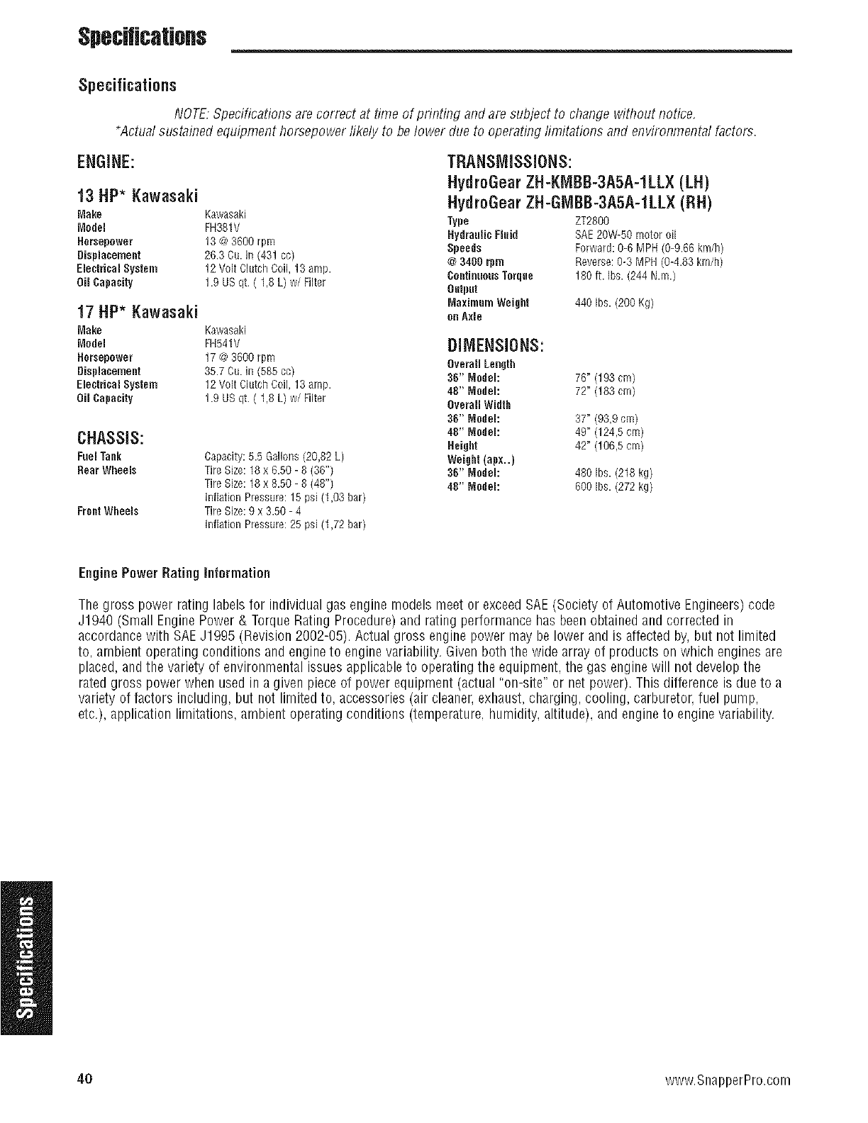
$pecHicaUons
Specifications
NOTE:Specifications are correct at time of printing and are subject to change without notice,
*Actual sustained equipmenthorsepower likely to be lower due to operating limitations and environmental factors.
ENGINE:
13 HP* Kawasaki
TRANSMISSIONS:
HvdroGearZH-KMBB-3A5A-1LLX(LH)
HvdroGearZH-GIVIBB-3A5A-1LLX(RH)
Make Kawasaki
Model FH381V Type ZT2800
HydranlicRuid SAE20W-50motoroil
Hereepower 13@3600rpm Speeds Forward:0-6MPH(0-9.66km/h)
Displacement 26.3Cu.in(431cc) @3400rpm Reverse:0-3MPH(04.83km/h)
ElectricalSystem 12VoltClutchCoil,13amp. ContinuousTorque 180ft. Ibs.(244N.m.)
Od Capacity 1.9USqt. ( 1,8 L) w/Filter Output
MaximumWeight 440Ibu.(200Kg)
17 HP* Kawasaki oeAxle
Make Kawasaki
Model FH541V
Hemepower 17@3600rpm
Displacement 35.7Cu.in(585cc)
ElectricalSystem 12Volt ClutchCoil,13amp.
OilCapacity 1.9USqt.( 1,8L) w/Filter
CHASSIS:
Fuel Tank
Rear WheeJs
Frent Wheels
Capacity: 5.5 GalloNs (20,82 L)
Tire Size: 18 x 6.50 - 8 (36")
Tire Size: 18 x 8.50 - 8 (48")
Inflation Pressure: 15 psi (1,03 bar)
Tire Size: 9 x 3.50 - 4
Inflation Pressure: 25 psi (1,72 bar)
DIMENSIONS:
Overall Length
36" Model: 76" (193 crn)
48" Model: 72" (183 cm)
OverallWidth
36"Model: 37" (93,9 cm)
48"Model: 49"(124,5cm)
Height 42"(106,5cm)
Weight (apx..)
36"Model: 480Ibs.(218kg)
48"Model: 600Ibs.(272 kg)
Engine Power Rating information
The gross power rating labels for individual gas engine models meet or exceedSAE(Society of Automotive Engineers) code
J1940 (Small EnginePower & Torque Rating Procedure) and rating performance has been obtained and corrected in
accordancewith SAEJ1995 (Revision 2002-05). Actual gross engine power may be lower and is affected by, but not limited
to, ambient operating conditions and engine to enginevariability. Given both the wide array of products on which engines are
placed, andthe variety of environmental issues applicable to operating the equipment, the gas engine will not develop the
rated gross power when used in a given piece of power equipment (actual "on-site" or net power). This difference is due to a
variety of factors including, but not limited to, accessories (air cleaner,exhaust,charging, cooling, carburetor, fuel pump,
etc.), application limitations, ambient operating conditions (temperature. humidity, altitude), and engineto engine variability.
40 www.SnapperPro.com
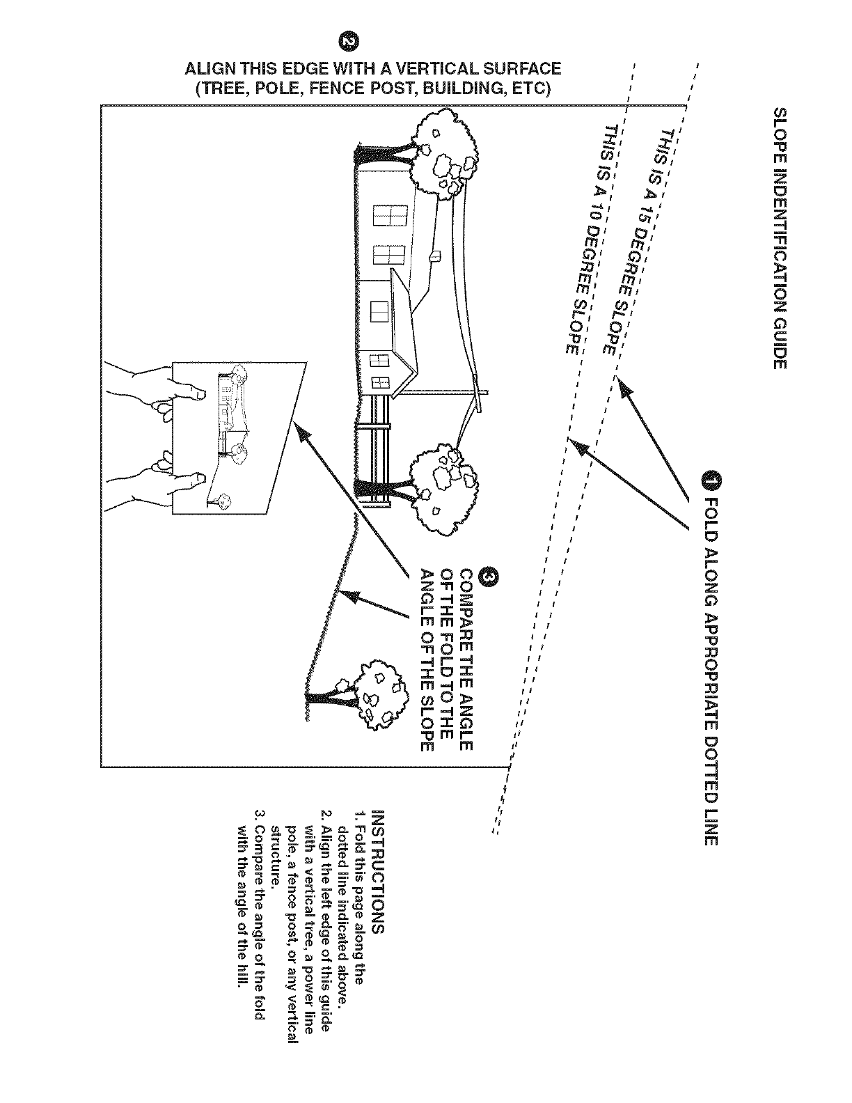
ALIGN THiS EDGE WiTH A VERTICAL SURFACE
(TREE, POLE, FENCE POST, BUiLDiNG, ETC)
z=n
0=4
r==r,
mm
==,=
m=,_
Oz
m
m
__ _.=--
_$" .""o •o
o'=o _=
==.= = -_ _. _. _.
_= _
• ,< _ $'<o
Z o<_. °
o
0
_J
m
m
m
I
I
I
I
t!
tl
1!
i1
F
"4
I
t
O)
r"
0
m
m
=_
N
N
m

Notes

Notes

Snapper Pro -adivision of Briggs & Stratton Power Products Group, LLC.
Owner's Limited Warranty information
(Effective 08/01/2007)
Thank you for purchasing Snapper Pro commercial mowing equipment. Please take a few minutes to read this limited warranty information. It con-
tains all the information you will need to have your Snapper Pro mower repaired in the unlikely event that a breakdown covered by this limited warranty
should occur.
Owner's Responsibilities - As a condition to our obligations under this limited warranty, you shall have read the operator's manual and you shall have
completed and submitted to Snapper Pro, within 20 days from the date of purchase, the Snapper Pro Product Registration. You must properly service
and maintain your Snapper Pro product as described in the operator's manual. Such routine maintenance, whether performed by a dealer or by you, is
at your expense. The Snapper Pro equipment, including any defective part covered by this limited warranty, must be returned to an authorized Snapper
Pro dealer within the warranty period for warranty service. This limited warranty extends only to equipment operated under normal conditions and in
accordance with Snapper Pro' instructions.
Warranty Start Date - The limited warranty coverage begins on the day you buy your new Snapper Pro commercial mowing equipment. An authorized
Snapper Pro dealer will assist you in filling out a Snapper Pro Product Registration with specific information for the model you purchase and your per-
sonal information, which must be returned to Snapper Pro.
Limited Warranty - The limited warranty, set forth below, is a written guarantee by Snapper Pro, during the warranty period, to repair or replace parts
which have a substantial defect in materials or workmanship. The warranty is "limited" because it is for a specified period of time, applies to the origi-
nal purchaser only, and is subject to other restrictions.
SNAPPER PRO LiMiTED WARRANTY
Snapper Pro warrants, in accordance with the provisions below, to the original purchaser only, for the periods described below that the commercial
mower shall be free from substantial defects in material or workmanship under normal use and service. If you wish to file a claim under this limited
warranty, you must provide prompt notice of your claim to an authorized Snapper Pro dealer during the warranty period. Snapper Pro' obligation under
this limited warranty is, at Snapper Pro' option, to repair or replace any part or parts of the mower, which, in the judgment of Snapper Pro, are found to
be defective and covered by this limited warranty. An authorized Snapper Pro dealer will repair or replace the defective part or parts, at the dealer's
place of business, at no charge for the labor or parts. This limited warranty applies only to mowers sold in the United States and Canada and is sub-
ject to the following limitations.
Covered Parts
All Mowers Warranty Period
2-years (24 months) from date of retail purchase by the original
purchaser for parts & labor (90 days for rental mowers)
(Except as noted below*)
*Belts, Tires, Brake Pads
And Hoses, Battery, Blades 90 days from date of retail purchase by the original purchaser
*Attachments 1 year from date of retail purchase by the original purchaser
*Engine If the engine manufacturer provides any warranty on the mower's engine, Snapper Pro will assign that
warranty to the original purchaser of the mower if such assignment is reasonably practicable. Please refer to
the engine manufacturer's warranty statement, if any, that is included in the owner's packet. We are not
authoized to handle warranty adjustments or repairs on engines. Snapper Pro offers NO WARRANTY on
mower engines. Snapper Pro does not guarantee or represent that any engine manufacturer will comply with
the terms of its warranty.
items and Conditions Not Covered
This warranty does not cover, and Snapper Pro makes NO WARRANTY regarding, the following:
Mowers or their parts if a complete and accurate Snapper Pro Product Registration has not been received by Snapper Pro.
Loss or damage to person or property other than that expressly covered by the terms of this limited warranty.
Pickup and delivery charges and risk of loss or damage in transit to and from any authorized Snapper Pro dealer.
Any damage or deterioration due to normal use, wear and tear, or environmental or natural elements, or exposure.
Cost of regular maintenance service or parts, such as but not limited to, filters, fuel, lubricants, tune-up parts, and adjustments.
Claims arising due to failure to follow Snapper Pro' written instructions, or improper storage or maintenance.
Any repairs necessary due to use of parts, accessories or supplies, including gasoline, oil or lubricants, incompatible with the mowing equipment,
or other than as recommended in the operator's manual or other written operational instructions provided by Snapper Pro.
Use of non-Snapper Pro approved parts or accessories.
Any overtime or other extraordinary repair charges or charges relating to repairs or replacements.
Rental of like or similar replacement equipment during the period of any warranty, repair or replacement work.
Loss of revenue, time or use of the mowing equipment.
Travel, telephone or other communication charges.
Damage from continued use of defective mowing equipment.
Freight charges on replacement parts.
Any mowing equipment or part which, in the judgment of Snapper Pro, has been altered or tampered with in any way or has been subjected to
misuse, abuse, abnormal usage, unauthorized repair, neglect or accident, damage in transit, or has had the serial numbers altered, effaced or
removed.
•Any equipment, part or item not mentioned under "Covered Parts," above.
General Conditions
Snapper Pro is continually striving to improve its products, and therefore reserves the right to make improvements or changes without incurring any
obligation to make changes or additions to products sold previously. Any oral or written description of Snapper Pro products is for the sole purpose of
identifying the products and shall not be construed as an express warranty. No warranty claim shall give rise to a right for the purchaser to cancel or
rescind any sale. No person is authorized to make any warranty or assume for Snapper Pro any liability not strictly in accordance with this limited war-
ranty. Any assistance Snapper Pro provides to or procures for the purchaser outside the terms, limitations or exclusions of this limited warranty will not
constitute a waiver of the terms, limitations or exclusions of this limited warranty, nor will such assistance extend or revive the limited warranty.
Snapper Pro will not reimburse the purchaser for any expenses incurred by the purchaser in repairing, correcting or replacing any defective products
except for those incurred with Snapper Pro' prior written permission and in accordance with this limited warranty.
Snapper Pro' sole and exclusive liability with respect to this limited warranty, and the purchaser's exclusive remedy, shall be repair or replacement as
set forth herein. All warranty work must be performed by an authorized Snapper Pro dealer using only Snapper Pro approved replacement parts.
SNAPPER PRO SHALL HAVE NO LIABILITY FOR ANY OTHER COST, LOSS OR DAMAGE, INCLUDING BUT NOT LIMITED TO, ANY INCIDEN-
TAL, COMPENSATORY, INDIRECT, PUNITIVE, SPECIAL OR CONSEQUENTIAL LOSS OR DAMAGE. SNAPPER PRO' AGGREGATE LiABILiTY
WiTH RESPECTTO A DEFECTIVE PRODUCT OR PART SHALL BE LIMITED TO AN AMOUNT EQUALTOTRE MONIES PAiD BYTHE PUR-
CHASER FOR THAT DEFECTIVE PRODUCT OR PART. THIS LIMITED WARRANTY, AND SNAPPER PRO' OBLiGATiONS HEREUNDER, ARE
EXCLUSIVE AND iN LIEU OF ALL OTHER WARRANTIES, EXPRESS OR iMPLiED, INCLUDING, WITHOUT LIMITATION, THE IMPLIED WARRAN-
TY OF MERCHANTABiLiTY ANDTHE IMPLIED WARRANTY OF FITNESS FOR A PARTICULAR PURPOSE. SNAPPER PRO SHALL NOT BE
LIABLE TO THE PURCHASER, OR TO ANYONE CLAIMING UNDER THE PURCHASER, FOR ANY OTHER OBLIGATIONS OR LIABILITIES,
iNCLUDiNG, BUT NOT LIMITED TO, OBLIGATIONS OR LIABILiTiES ARISING OUT OF BREACH OF CONTRACT OR WARRANTY, NEGLIGENCE
OR OTHER TORT OR ANYTHEORY OF STRICT LIABiLITY, WITH RESPECT TO SNAPPER PRO PRODUCTS OR SNAPPER PRO' ACTS OR
OMiSSiONS OR OTHERWISE.
It is the express wish of the parties that this agreement and any related documents be drafted in English. II est la volont_ expresse des parties que
cette convention et tousles documents s'y rattachent soient r_dig_s en anglais.

oOPERATOR'S
MANUAL
SW20Series
Walk-BehindMowers
ProductSpecifications:
ENGINE:
13 HP Kawasaki
Make Kawasaki
Medel FH381V
Oil Capacity 1.9 US qt. ( 1.8 L) w/Filter
17 HP Kawasaki
Make Kawaeaki
Model FH541V
OiJCapacity 1.9 US qt. ( 1.8 L) w/Filter
CHASSIS:
Fuel Tank
Bear Wheels
Frcnt Wheels
Capacity: 5.5 GalloNs (20,82 L)
Tire Size: 18 x 6.50 - 8 (36" Model)
Tire Size: 18 x 8.50 - 8 (48" Model)
Inflation Pressure: 15 psi (1,03 bar)
Tire Size: 9 x 3.50 - 4
Inflation Pressure: 25 psi (1,72 bar)
CommonService Parts:
BELTSAND BLADES:
TRACTOR
Pump Drive BeJt 5021770
36" MOWERDECK
Deck Drive Belt 5101313
Mower Blade 5021227
48" MOWERDECK
Deck Drive Belt 5021650
Mower Blade 5020843
Briggs & StrattonPower ProductsGroup
5375 North Main Street
Munnsville, NY 13409
800-933-6175
www.SnapperPro.com
