SOLiD 19PAWS1MIMO RDU Module (1900P/AWS-1 (MIMO)) User Manual MB DAS
SOLiD, Inc. RDU Module (1900P/AWS-1 (MIMO)) MB DAS
SOLiD >
User Manul
Confidential & Proprietary 1/28
SMDR-NH124(Remote Unit)
User Manual
Document Reference:
Version: V1.0
Document Status: Release 1
Issue Date: July. 16, 2014
Author: Young Ju YOU
Department: R&D Division Team 3
Authorizing Manager: Young shin Yeo

Confidential & Proprietary 2/28
REVISION HISTORY
Version
Issue Date
No. of
Pages
Initials
Details of Revision Changes
V 1.0
July. 16, 2014
Original
Technical Support
SOLiD serial numbers must be available to authorize technical support and/or to establish a
return authorization for defective units. The serial numbers are located on the back of the unit,
as well as on the box in which they were delivered. Additional support information may be
obtained by accessing the SOLiD Tehcnology, Inc. website at www.st.co.kr or send email at
sjkim@st.co.kr
This manual is produced by Global Business Division Business Team 1. Printed in Korea.

Confidential & Proprietary 3/28
Contents
Section1 Safety & Certification Notice ................................................................. 5
Section2 System Overview .................................................................................... 8
2.1 Purpose ......................................................................................................... 9
2.2 SMDR-NH124 .............................................................................................. 10
Section3 Functional Description ......................................................................... 11
3.1 General (Remote Optic Unit) ...................................................................... 12
3.2 Component of SMDR-NH124 Remote Unit ................................................ 13
3.3 Dimension ................................................................................................... 15
Section4 System Installation ............................................................................... 16
4.1 ROU Installation ......................................................................................... 16
4.1.1 ROU Enclosure installation ................................................................. 16
4.1.2 ROU Power Cabling ............................................................................. 20
4.1.3 Optical Cabling ..................................................................................... 21
4.1.4 GND Terminal Connection ................................................................... 22
4.1.5 Coaxial cable and Antenna Connection .............................................. 23
4.1.6 Insertion of RDU ................................................................................... 23
4.1.7 RDU Specifications Per band .............................................................. 24

Confidential & Proprietary 4/28
Contents of Figure
Figure 3.1 – Remote Unit Block Diagram ...................................................... 12
Figure 3.2 – Inside of Remote Unit ............................................................... 13
Figure 3.3 – ROU Outer Look ....................................................................... 15
Figure 4.1 – How to install ROU .................................................................... 17
Figure 4.2 – Dimension used to install ROU on the WALL ............................ 17

Confidential & Proprietary 5/28
Section1
Safety & Certification Notice

Confidential & Proprietary 6/28
“Only qualified personnel should handle the DAS equipment. Any person involved in
installation or service of the DAS should understand and follow these safety guidelines.”
- Obey all general and regional installation and safety regulations relating to work on high
voltage installations, as well as regulations covering correct use of tools and personal
protective equipment.
- The power supply unit in repeaters contains dangerous voltage level, which can cause electric
shock. Switch the mains off prior to any work in such a repeater. Any local regulations are to
be followed when servicing repeaters.
- When working with units outdoors, make sure to securely fasten the door or cover in an open
position to prevent the door from slamming shut in windy conditions..
- Use this unit only for the purpose specified by the manufacturer. Do not carry out any
modifications or fit any spare parts which are not sold or recommended by the manufacturer.
This could cause fires, electric shock or other injuries.
- Any DAS system or Fiber BDA will generate radio (RF) signals and continuously emit RF
energy. Avoid prolonged exposure to the antennas. SOLiD recommends maintaining a 3-foot
minimum clearance from the antenna while the system is operating.
- Do not operate this unit on or close to flammable materials, as the unit may reach high
temperatures due to power dissipation.
- Do not use any solvents, chemicals, or cleaning solutions containing alcohol, ammonia, or
abrasives on the DAS equipment. Alcohol may be used to clean fiber optic cabling ends and
connectors.
- To prevent electrical shock, switch the main power supply off prior to working with the DAS
System or Fiber BDA. Never install or use electrical equipment in a wet location or during a
lightning storm.
- Do not look into the ends of any optical fiber or directly into the optical transceiver of any digital
unit. Use an optical spectrum analyzer to verify active fibers. Place a protective cap over any
radiating transceiver or optical fiber connector to avoid the potential of radiation exposure.
- Allow sufficient fiber length to permit routing without severe bends.
- For pluggable equipment, make sure to install the socket outlet near the equipment so that it is
easily accessible.
- A readily accessible disconnect device shall be incorporated external to the equipment.
Confidential & Proprietary 7/28
- This power of this system shall be supplied through wiring installed in a normal building.
If powered directly from the mains distribution system, it shall be used additional protection,
such as overvoltage protection device
- Only 50 ohm rated antennas, cables and passive equipment shall be used with this remote.
Any equipment attached to this device not meeting this standard may cause degradation and
unwanted signals in the bi-directional system. All components connected to this device must
operate in the frequency range of this device.
- Only 50 ohm rated antennas, cables and passive components operating from 150 - 3 GHz
shall be used with this device.
- The head end unit must always be connected to the Base Station using a direct cabled
connection. This system has not been approved for use with a wireless connection via
server antenna to the base station.
- Signal booster warning label message should include
- Certification
FCC: This equipment complies with the applicable sections of Title 47 CFR Parts
15,22,24,27 and 90(Class B)
UL/CUL: This equipment complies with UL and CUL 1950-1 Standard for safety for
information technology equipment,including electrical business equipment
FDA/CDRH: This equipment uses a Class 1 LASER according to FDA/CDRH Rules.This
product conforms to all applicable standards of 21 CFR Chapter 1, Subchaper J, Part
1040

Confidential & Proprietary 8/28
Section2
System Overview
2.1 Purpose
2.2 SMDR-NH124

Confidential & Proprietary 9/28
2.1 Purpose
SMDR-NH124 is a coverage system for in-building services delivering voice and data in high
quality and for seamlessly.
As a distributed antenna system, it provides analog and digital phone systems that are served in
multiple bands through one antenna.
The system covers general public institutions and private facilities.
Shopping malls
Hotels
Campus areas
Airports
Clinics
Subways
Multi-use stadiums, convention centers, etc.
The system helps improve in-building radio environments in poor condition and make better
poor RSSI and Ec/Io. By providing communication services at every corner of buildings, the
system enables users to make a call at any site of buildings.
The system uses both analog (AMPS) and digital (TDMA, CDMA and WCDMA) methods.
The SMDR-NH124 system supports communication standards and public interface protocols in
worldwide use.
Frequencies: VHF,UHF, 700MHz, 800MHz,850MHz 900MHz,1900MHz,2100MHz, etc.
Voice protocols: AMPS,TDMA, CDMA,GSM,IDEN, etc.
Data protocols: EDGE,GPRS,WCDMA,CDMA2000,Paging, etc.
SMDR-NH124 is in modular structure per frequency. To provide desired frequency in a building,
all you need to do is to insert a corresponding frequency module into each unit. As it delivers
multiple signals with one optical cable, the system, in one-body type, does not require additional
facilities whenever new frequency is added.
The system is featured with the following:
Flexibiltiy & Scalabiltiy
Support fiber-optic ports up to 39
Clustering multiple-buildings (campus) as one coverage
Modular structures
Modular frequency upgrade
Plug-in type module
Multi-Band, Multi Operator

Confidential & Proprietary 10/28
Signals with a plurality of service provider transmit simultaneously
Support multi-operator in a band
Low OPEX / CAPEX
Compact design
Upgradable design
Easy installation and maintenance
Web Based SNMP or GSM Modem or UDP support (Optional)
2.2 SMDR-NH124
ROU receives TX optical signals from ODU or OEU and converts them into RF signals. The
converted RF signals are amplified through High Power Amp in a corresponding RDU,
combined with Multiplexer module and then radiated to the antenna port.
When receiving RX signals through the antenna port, this unit filters out-of-band signals in a
corresponding RDU and sends the results to Remote Optic Module to make electronic-optical
conversion of them. After converted, the signals are sent to a upper device of ODU or OEU.
ROU can be equipped with up to three RDUs (Remote Drive Unit) and the module is composed
of maximal Dual Band.

Confidential & Proprietary 11/28
Section3
Functional Description
3.1 General (Remote Optic Unit)
3.2 Compoent of SMDR-NH124 Remote Unit
3.3 Dimension
Confidential & Proprietary 12/28
3.1 General (Remote Optic Unit)
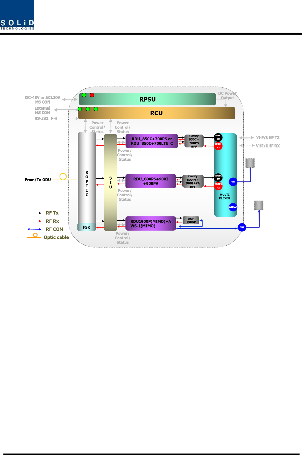
The following figure shows the block diagram of SMDR-NH124 Remote Unit.
Figure 3.1 – Remote Unit Block Diagram
There are many components;
R-Optic : Remote Optical Unit
RCPU : Remote Central Processor Unit
RPSU(AC) : Remote AC Power Supply Unit(When using the AC input power)
RPSU(DC) : Remote DC Power Supply Unit(When using the DC input power)
RDU1-3 : Remote Drive Unit
MULTIPLEXER : Combine Unit
SIU : System Interface Unit
Confidential & Proprietary 13/28
3.2 Component of SMDR-NH124 Remote Unit
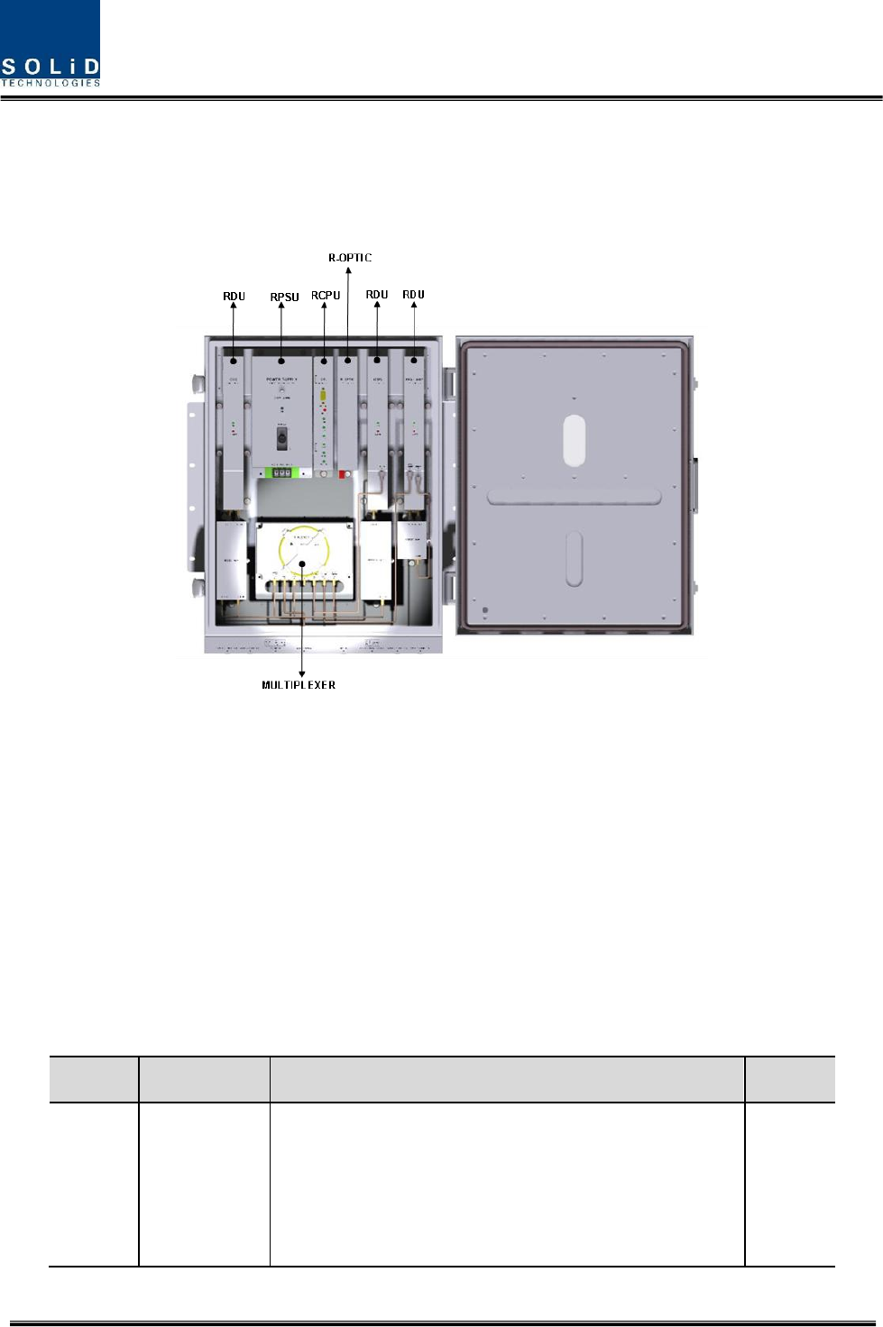
The following figure shows internal configuration of Remoe Unit with fully RF equipped.
Figure 3.2 – Inside of Remote Unit
Remote Unit receives TX optical signals from Head-End and converts them into RF signals. The converted
RF signals are amplified through High Power Amp in a corresponding RDU, combined with Multiplexer
module and then radiated to the antenna port.
When receiving RX signals through the antenna port, this unit filters out-of-band signals in a
corresponding RDU and sends the results to Remote Optic Module to make electronic-optical
conversion of them. After converted, the signals are sent to a upper device of ODU. ROU can be
equipped with up to three RDUs (Remote Drive Unit)
The following table describes components on Remote Unit
No.
Unit
Description
Remark
1
RDU+BPF
Remote Drive Unit
Filter and high amplify TX signals;
Filter and amplify RX signals;
Remove other signals through BPF
BPF is exclude from VHF+UHF module

Confidential & Proprietary 14/28
2
RPSU
Remote Power Supply Unit
Input power: DC -48V, Output power: 27V,9V, 6V
For 120V input of AC/DC;
For -48V input of DC/DC
3
R-OPTIC
Remote Optic
Make RF conversion of TX optical signals;
Convert RX RF signals into optical signals;
Compensates optical loss
Communicates with BIU/OEU though the FSK modem
4
RCPU
Remote Central Processor Unit
Controls signal of each unit
Monitors BIU/ODU/OEU status through FSK modem
communication
5
Multiplexer
Multiplexer
Combine TX signals from 3 RDUs;
Distribute RX signals to 3 RDUs;
Enable you to use a single antenna port
6
Enclosure
Enclosure to satisfy NEMA4;
Enable Wall/Rack Mount;
Check if the system is normal, through the front panel
LED
7
SIU
System Interface Unit
Distribute power and signals of each module
Confidential & Proprietary 15/28
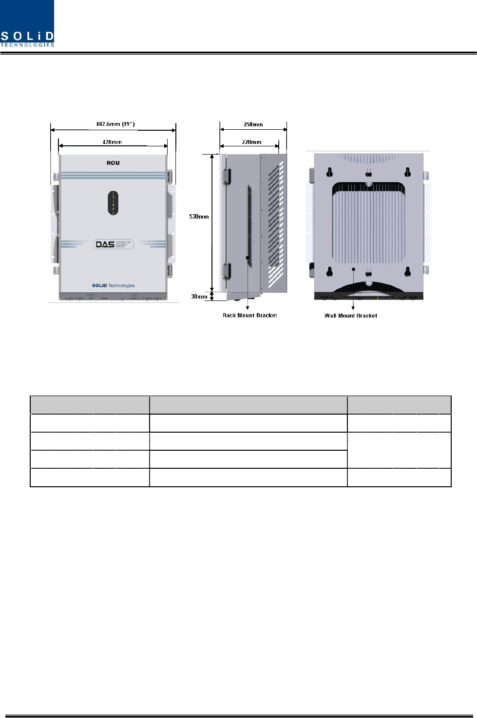
3.3 Dimension
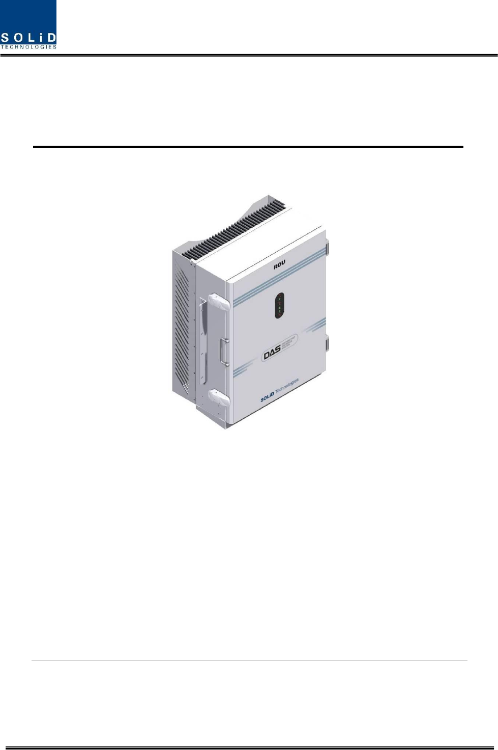
Figure 3.3 – ROU Outer Look
ROU is designed in a cabinet, and provides the following functions and features.
Item
Spec.
Remark
Size(mm)
482.6(19“) x 258 x560,
Including Bracket
Weight
35.45 Kg
Full Load
Power consumption
265 W
Operating Temperature
-10 to +50°C
Ambient Temperature

Confidential & Proprietary 16/28
Section4
System Installation
4.1 ROU Installation
4.1.1 ROU Enclosure installation
ROU is designed to be water- and dirt-proof. The unit has the structure of One-Body enclosure.
It satisfies water-proof and quake-proof standards equivalent of NEMA4.
ROU can be mounted into either of a 19” Standard Rack or on a Wall.
Basically, ROU has both of a Wall Mount Bracket and a Rack Mount Bracket.
Depending on the use of the Rack Mount Bracket, the bracket can be removed.
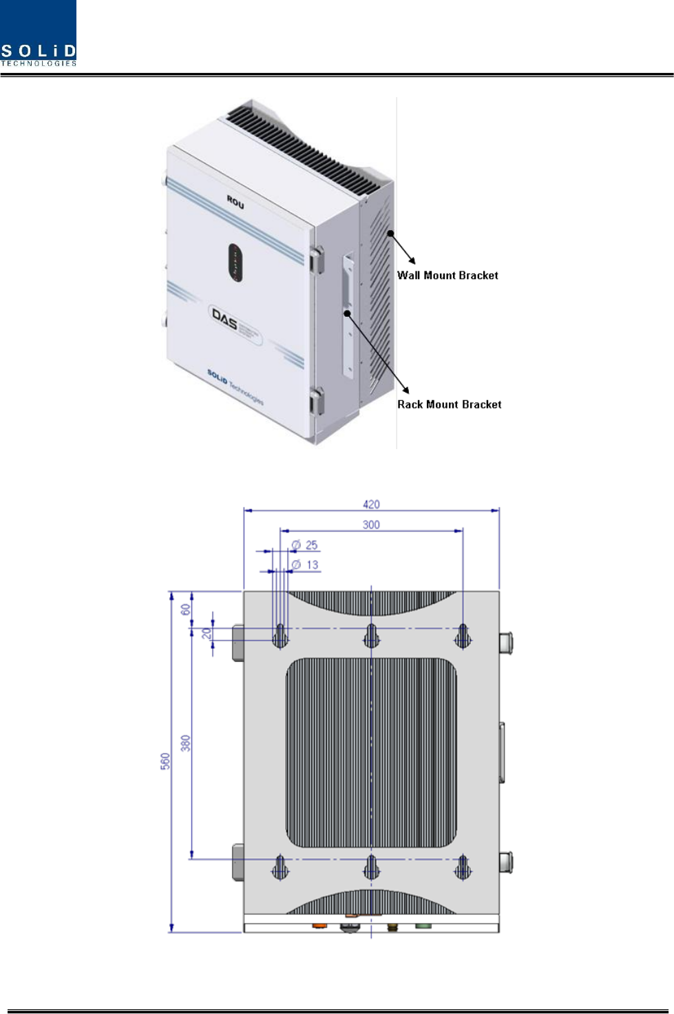
The following shows dimension of the fixing point for the Wall Mount Bracket.
Confidential & Proprietary 17/28
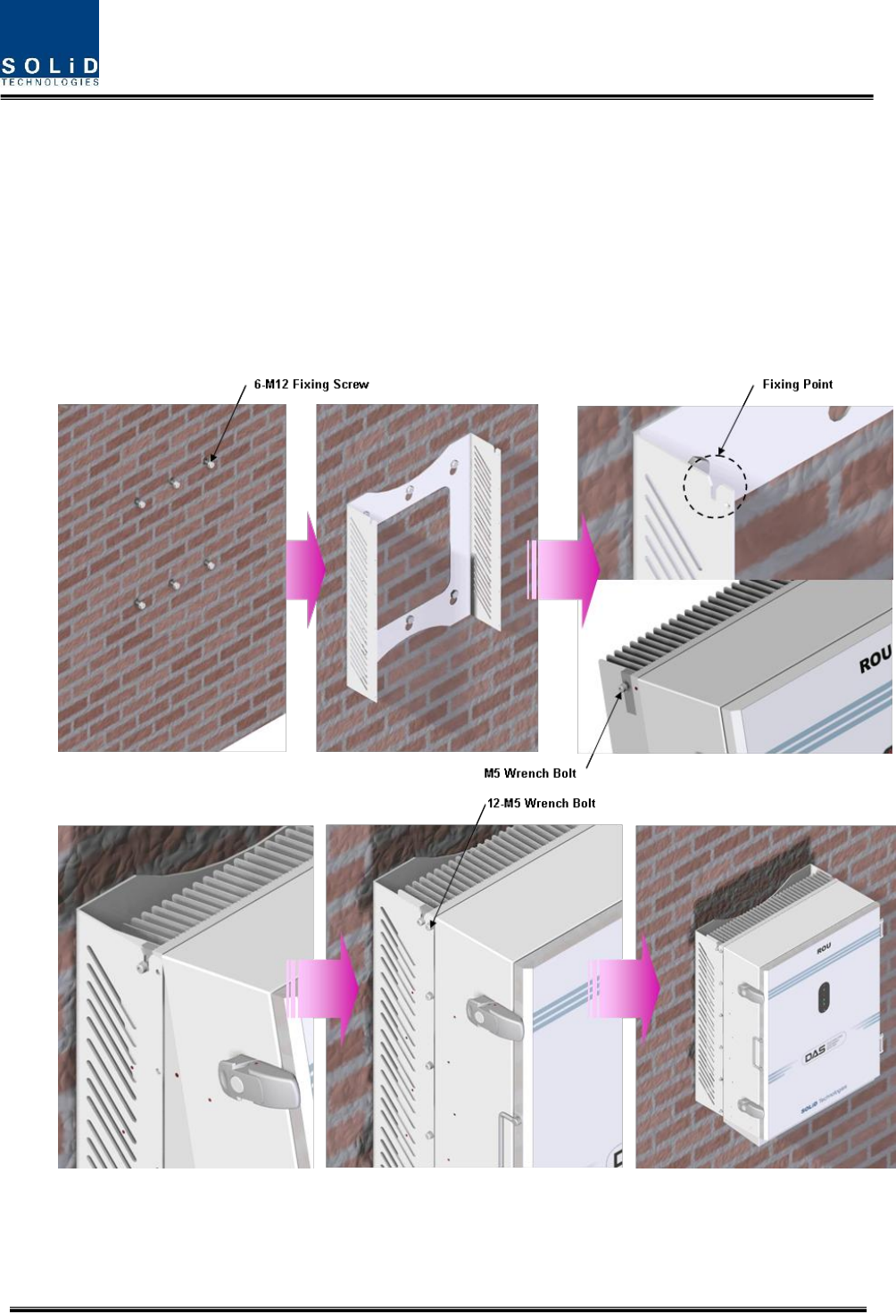
Figure 4.1 – How to install ROU
Figure 4.2 – Dimension used to install ROU on the WALL
Confidential & Proprietary 18/28
ROU Wall Mount Installation
Turn M12 Fixing Screws by half on the wall and fully fix the screw with a Wall Mount Bracket on
it.
For convenience, the Wall Mount Bracket has fixing holes to let you easily mount an enclosure.
Turn the M5 Wrench Bolt by half at each side of the Heatsink of the enclosure.
Put the enclosure with the M5 Wrench Bolt fixed on the fixing groove and fix the M5 Wrench
Bolts into the remaining fixing holes.
In this case, you will use 12 M5 Wrench Bolts in total except bolts used for the fixing groove.
Confidential & Proprietary 19/28
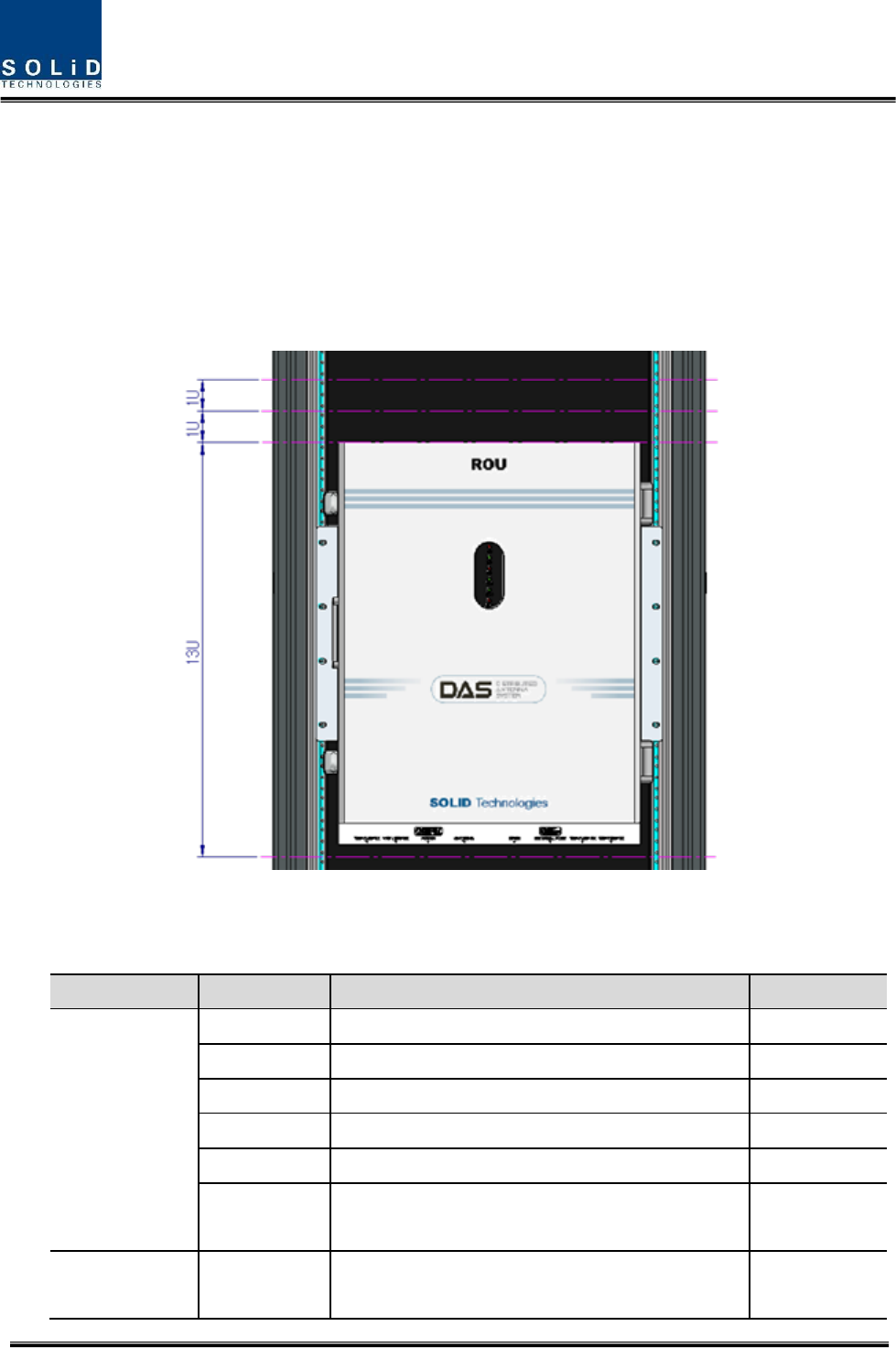
ROU Rack Mount Installation
Like other units, ROU is designed to be inserted into a rack. The unit occupies around 13U of
space except cable connection.
ROU component
ROU has the following components:
No.
Unit
Description
Remark
Common Part
Enclosure
Including Rack & Wall cradle
1EA
RCPU
-
1EA
R_OPTIC
With SC/ACP adaptor
1EA
RPSU
Alternative DC-48V or AC 120V
1EA
Multi-Plexer
-
1EA
Power Cable
- MS Connector with 3 hole to AC 120 plug(AC)
- MS Connector with 2 lug termination(DC)
Optional Part
RDU+BPF
800PS,800PS+900I+Paging,850C,850C+700PS,
1900P+ AWS-1 RDU, VHF+UHF(NO BPF),
Up to 3EA to
be inserted
Confidential & Proprietary 20/28
850C+700LTEC, 700LTEF+850C
700LTEF SISO RDU, 700LTEF SISO RDU
Basically, the common part of ROU should have an enclosure and it is equipped with RCPU to
inquire and control state of each module, R_OPTIC to make both of electronic-optical and
optical-electronic conversions, RPSU to supply power for ROU and a Multi-Plexer to help share
multiple TX/RX signals through one antenna. It should have Power Cable for external rectifier or
to supply required power.
In addition, RDU can be inserted and removed to provide service for desired band (Optional).
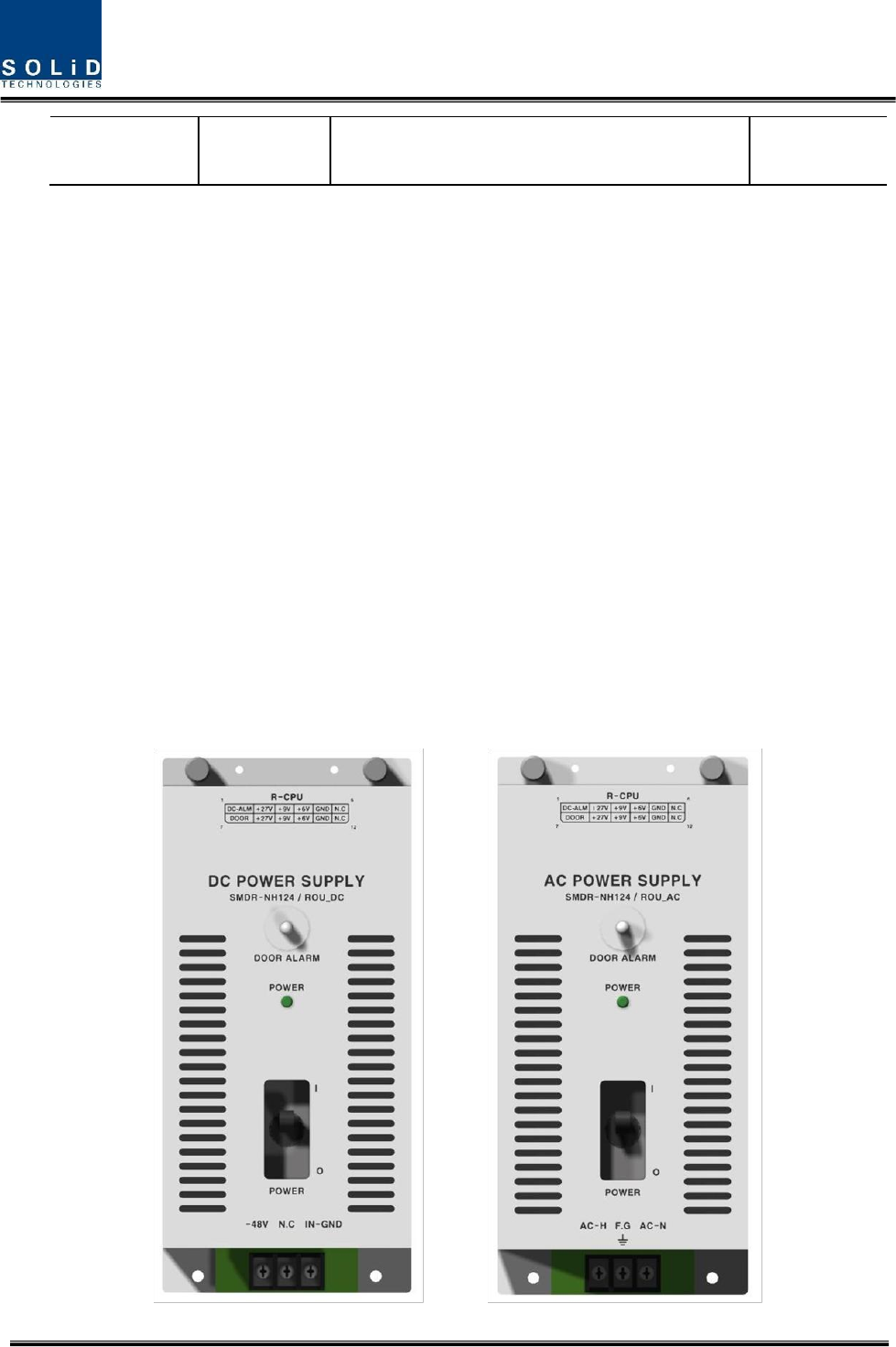
4.1.2 ROU Power Cabling
ROU supports both of DC-48V and AC120V of input power. As RPSU for DC-48 and RPSU for
AC120V are separated from each other, you need to select one of them in case of purchase
order.
RPSU for DC -48V and RSPU for AC 120V have the same configuration and capacity while
each of the units uses different input voltage from each other.
The following figure shows configuration of RPSUs for DC -48V and AC 120V.
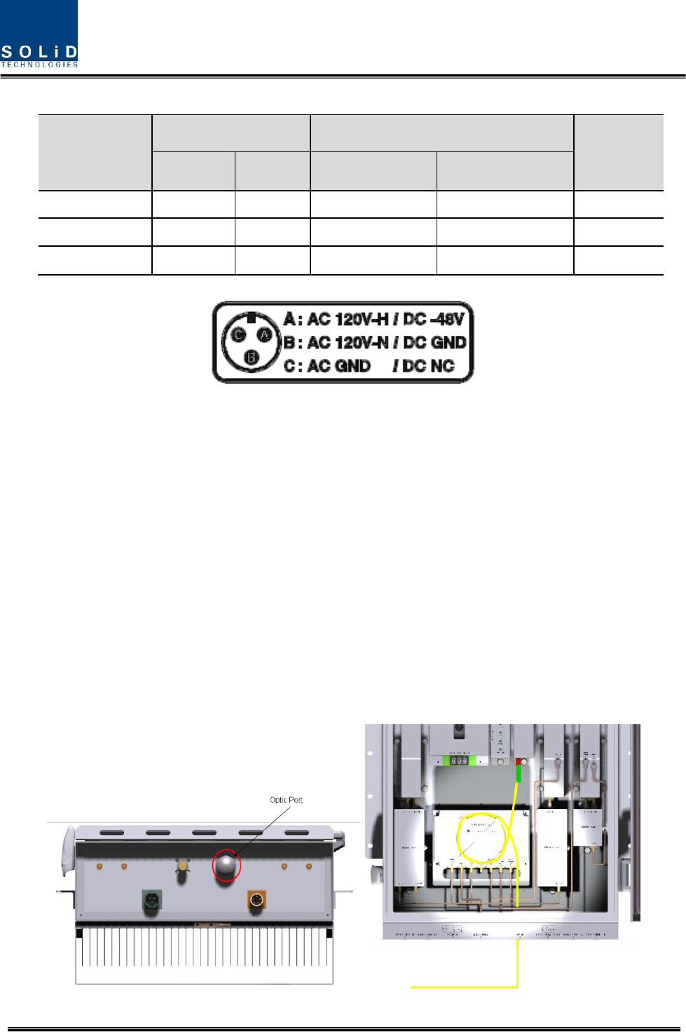
Confidential & Proprietary 21/28
MC Connector
numbering
Lug Naming
RPSU Terminal naming
Remark
AC
DC
AC
DC
A
AC_H
-48V
AC-H
-48V
B
AC_N
GND
AC-N
IN_GND
C
GND
DC NC
FG
FG
Check if the connection is the same as one seen in the table above and make sure to turn the
power ON.
4.1.3 Optical Cabling
ROU makes optical-electronic conversion of TX signals from upper ODU and OEU and makes
electronic- optical conversion of RX signals. ROU has one optical module in it. As WDM is
installed in the R_OPTIC module, two pieces of wavelength (TX:1310nm, RX:1550nm) can be
sent/received with one optical core at the same time. ROU has SC/APC of optical adaptor type.
For optical adaptor, SC/APC type can be used. To prevent the optical access part from being
marred with dirt, it should be covered with a cap during move. When devices are connected
through optical cables, you need to clear them using alcohocol to remove dirt.
Confidential & Proprietary 22/28
Optical cables should be inserted into Optic Port outside of ROU. Using an optical slack devices
in ROU, you need to coil around one or two roll of cables to be connected with the optical
adaptor of ROPTIC.
At this time, curvature of the optical cable should be at least 10Ø to prevent insertion loss from
being increased.
Through GUI, check if PD value of ROPTIC is in a tolerable range (+4~-1dBm).
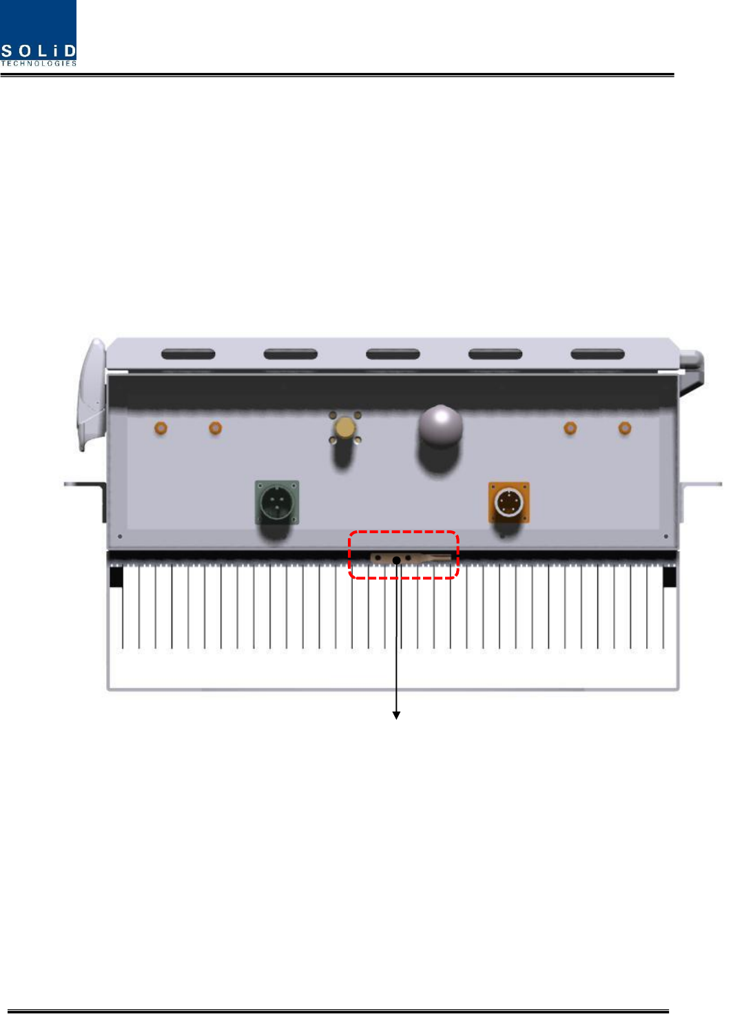
4.1.4 GND Terminal Connection
ROU has one GND terminal port where is on bottom side, like below
- Take off the GND terminal port from enclosure and connect to ground cable, then fix it
the position of enclosure again
- The opposite end of the ground cable should connect to the communication GND of
building
GND LUG

Confidential & Proprietary 23/28
4.1.5 Coaxial cable and Antenna Connection
- The coaxial cables which are connected to antenna distribued network connect to
antenna port of ROU. Before connection, check the VSWR value of coaxial cable
whether it is within specification using SITEMASTER .
- At this time, check if the Return loss have above 15Db or VSWR have below 1.5
- The part of antenna connection fasten to port not to be loosed and not to be injected
the dusty and insects
- The antenna connected to ROU is only serviced in inbuilding
4.1.6 Insertion of RDU
ROU has slots to enable up to three RDU modules to be inserted into the unit.
You can insert a RDU into any slot. It is not possible to provide services with a RDU
module alone; you need to connect the module with Cavity BPF in any case.
The table below shows types of RDU and CAVITY BPF:
No
Unit naming
Cavity BPF
RF CABLE
Multiplexer Interface
TX
RX
1
RDU 800PS
800PS BPF
TX CABLE 1EA
RX CABLE 1EA
BPF OUT
RDM RX IN
2
RDU 850C
850C BPF
TX CABLE 1EA
RX CABLE 1EA
BPF TX
OUT
BPF RX IN
3
RDU
1900P+AWS-1
1900P DUP
TX/RX CABLE 1EA
RDM AWS+1900P
4
RDU
800PS+900I+PA
800PS+900I+PA
BPF
TX CABLE 1EA
RX CABLE 1EA
RDM TX
OUT
RDM RX IN
5
RDU
850C+700PS
850C+700PS
BPF
TX CABLE 1EA
RX CABLE 1EA
RDM TX
OUT
RDM RX IN
6
RDU
850C+700PS(D)
850C+700PS
BPF
TX CABLE 1EA
RX CABLE 1EA
RDM TX
OUT
RDM RX IN
7
RDU
VHF+UHF
-
TX CABLE 1EA
RX CABLE 1EA
-
-
8
RDU
E-VHF+UHF
-
TX CABLE 1EA
RX CABLE 1EA
-
-
9
RDU
850C+700LTEC
850C+700LTEC
BPF
TX CABLE 1EA
RX CABLE 1EA
RDM TX
OUT
RDM RX IN

Confidential & Proprietary 24/28
10
RDU
700LTEF+850C
700LTEF+850C
BPF
TX CABLE 1EA
RX CABLE 1EA
RDM TX
OUT
RDM RX IN
11
RDU
700LTEF SISO
700LTEF SISO
BPF
TX CABLE 1EA
RX CABLE 1EA
RDM TX
OUT
RDM RX IN
12
RDU
700LTEF MIMO
700LTEF SISO
BPF
TX CABLE 2EA
RX CABLE 1EA
RDM TX
OUT
RDM RX IN
13
1900P(MIMO)+
AWS-1(MIMO)
1900P DUP
TX/RX CABLE 1EA
RDM AWS+1900P
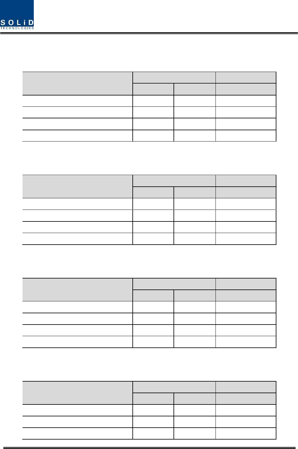
4.1.7 RDU Specifications Per band
Standard
Unit naming
Description
Frequency range
TX(MHz)
RX(MHz)
iDEN
700P
Public safety
758 to 775
793 to 805
700PS(D)
Public safety
763 to 775
788 to 805
iDEN
800P
Public safety
851 to 869
806 to 824
Cellular
850C
Cellular
869 to 894
824 to 849
Iden
900I
SMR
929 to 940
896 to 902
Paging
900 PA
Paging
929 to 930
896 to 902
PCS
1900P
PCS
1930 to 1995
1850 to 1915
AWS-1
AWS-1
AWS-1
2110 to 2155
1710 to 1755
-
VHF
Public safety
136 to 174
136 to 174
-
UHF
Public safety(Band1)
396 to 450
450 to 512
396 to 450
450 to 512
Public safety(Band2)
380 to 434
434 to 496
380 to 434
434 to 496
LTE
700LTE
Long Term Evolution
728 to 757
699 to 716
777 to 787
Confidential & Proprietary 25/28
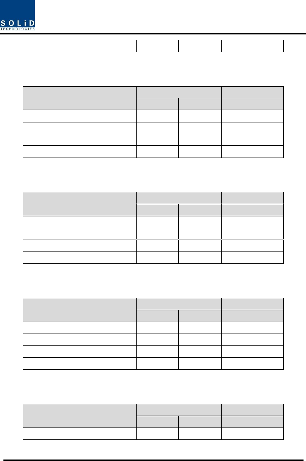
700MHz Long Term Evolution
Parameters
Typical
Remarks
TX
RX
Bandwidth
29MHz
28MHz
Output power
+23dBm
+0dBm
Total
System Gain
43dB
50dB
input and output impedances
50 ohm
50 ohm
700MHz Long Term Evolution (MIMO)
Parameters
Typical
Remarks
TX
RX
Bandwidth
29MHz
28MHz
Output power
+25dBm
+0dBm
Total
System Gain
45dB
50dB
input and output impedances
50 ohm
50 ohm
700MHz Public safety
Parameters
Typical
Remarks
TX
RX
Bandwidth
12MHz
12MHz
Output power
+23dBm
+0dBm
Total
System Gain
43dB
50dB
input and output impedances
50 ohm
50 ohm
700MHz Public safety (D Block)
Parameters
Typical
Remarks
TX
RX
Bandwidth
17MHz
17MHz
Output power
+23dBm
+0dBm
Total
System Gain
43dB
50dB
input and output impedances
50 ohm
50 ohm
Confidential & Proprietary 26/28
800MHz Public safety
Parameters
Typical
Remarks
TX
RX
Bandwidth
18MHz
18MHz
Output power
+23dBm
+0dBm
Total
System Gain
43dB
50dB
input and output impedances
50 ohm
50 ohm
850MHz Cellular
Parameters
Typical
Remarks
TX
RX
Bandwidth
25MHz
25MHz
Output power
+23dBm
+0dBm
Total
System Gain
43dB
50dB
input and output impedances
50 ohm
50 ohm
900MHz iDEN & Paging
Parameters
Typical
Remarks
TX
RX
Bandwidth
12MHz
6MHz
Output power
+23dBm
+0dBm
Total
System Gain
43dB
50dB
input and output impedances
50 ohm
50 ohm
1900MHz PCS
Parameters
Typical
Remarks
TX
RX
Bandwidth
65MHz
65MHz
Output power
+26dBm
+0dBm
Total
System Gain
46dB
50dB
Confidential & Proprietary 27/28
input and output impedances
50 ohm
50 ohm
1900MHz PCS(MIMO)
Parameters
Typical
Remarks
TX
RX
Bandwidth
65MHz
65MHz
Output power
+30dBm
+0dBm
Total
System Gain
50dB
50dB
input and output impedances
50 ohm
50 ohm
1700MHz&2100MHz AWS-1
Parameters
Typical
Remarks
TX
RX
Bandwidth
45MHz
45MHz
Output power
+26dBm
+0dBm
Total
System Gain
46dB
50dB
input and output impedances
50 ohm
50 ohm
1700MHz&2100MHz AWS-1(MIMO)
Parameters
Typical
Remarks
TX
RX
Bandwidth
45MHz
45MHz
Output power
+30dBm
+0dBm
Total
System Gain
50dB
50dB
input and output impedances
50 ohm
50 ohm
150MHz VHF Public safety
Parameters
Typical
Remarks
TX
RX
Bandwidth
38MHz
38MHz
136~174MHz

Confidential & Proprietary 28/28
Output power
+24dBm
-4dBm
Total
System Gain
39dB
50dB
input and output impedances
50 ohm
50 ohm
450MHz UHF Public safety
Parameters
Typical
Remarks
TX
RX
Bandwidth(Band1)
116MHz
116MHz
396~450MHz(54MHz)
450~512MHz(62MHz)
Band selection
Bandwidth(Band2)
116MHz
116MHz
380~434MHz(54MHz)
434~496MHz(62MHz)
Band selection
Output power
+24dBm
-4dBm
Total
System Gain
39dB
50dB
input and output impedances
50 ohm
50 ohm
"The Manufacturer's rated output power of this equipment is for single carrier operation.
For situations when multiple carrier signals are present, the rating would have to be
reduced by 3.5 dB, especially where the output signal is re-radiated and can cause
interference to adjacent band users. This power reduction is to be by means of input
power or gain reduction and not by an attenuator at the output of the device."
RSS-GEN, Sec. 7.1.2 – (transmitters)
Under Industry Canada regulations, this radio transmitter may only operate using an antenna of a
type and maximum (or lesser) gain approved for the transmitter by Industry Canada. To reduce
potential radio interference to other users, the antenna type and its gain should be so chosen that
the equivalent isotropically radiated power (e.i.r.p.) is not more than that necessary for successful
communication.
Conformément à la réglementation d’Industrie Canada, le présent émetteur radio peut fonctionner
avec une antenne d’un type et d’un gain maximal (ou inférieur) approuvé pour l’émetteur par
Industrie Canada. Dans le but de réduire les risques de brouillage radioélectrique à l’intention des
autres utilisateurs, il faut choisir le type d’antenne et son gain de sorte que la puissance isotrope
rayonnée quivalente (p.i.r.e.) ne dépassepas l’intensité nécessaire à l’établissement d’une
communication satisfaisante.
RSS-GEN, Sec. 7.1.2 – (detachable antennas)
This radio transmitter (identify the device by certification number, or model number if Category II)
has been approved by Industry Canada to operate with the antenna types listed below with the
maximum permissible gain and required antenna impedance for each antenna type indicated.
Antenna types not included in this list, having a gain greater than the maximum gain indicated for
that type, are strictly prohibited for use with this device.
Le présent émetteur radio (identifier le dispositif par son numéro de certification ou son numéro
de modèle s’il fait partie du matériel de catégorie I) a été approuvé par Industrie Canada pour
fonctionner avec les types d’antenne énumérés ci-dessous et ayant un gain admissible maximal et
l’impédance requise pour chaque type d’antenne. Les types d’antenne non inclus dans cette liste,
ou dont le gain est supérieur au gain maximal indiqué, sont strictement interdits pour l’exploitation
de l’émetteur.