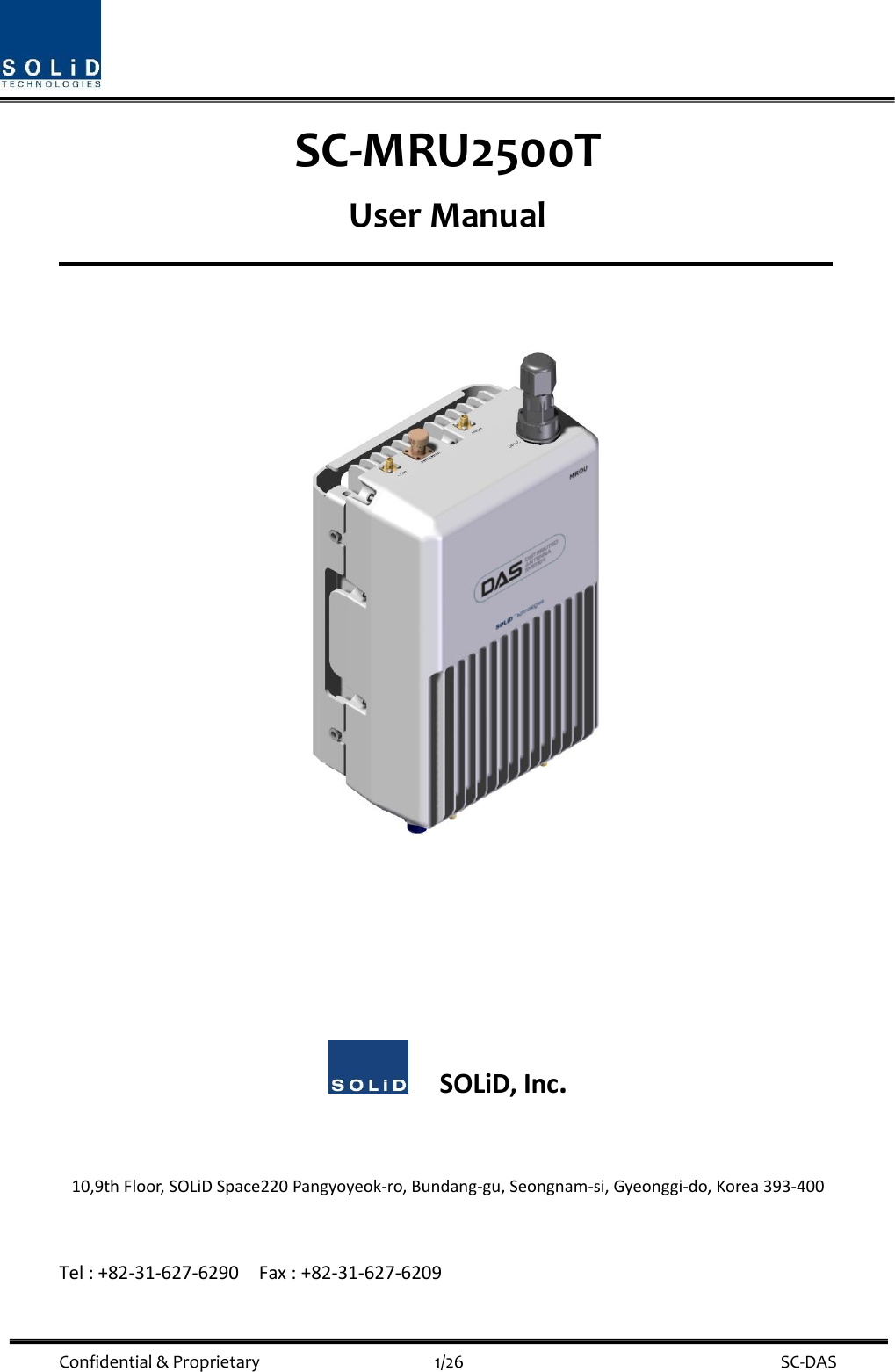
SOLiD 2500T SC-MRU2500T User Manual MB DAS

SOLiD, Inc. SC-MRU2500T MB DAS

User Manual_20150825_v1 - W6U2500T_User Manual

 Confidential & Proprietary                                      1/26    SC-DAS SC-MRU2500T User Manual            SOLiD, Inc.  10,9th Floor, SOLiD Space220 Pangyoyeok-ro, Bundang-gu, Seongnam-si, Gyeonggi-do, Korea 393-400  Tel : +82-31-627-6290    Fax : +82-31-627-6209
 Confidential & Proprietary                                      2/26    SC-DAS REVISION HISTORY Version Issue Date No. of Pages Initials Details of Revision Changes V 1.0 April. 13, 2015  Original                                                              Technical Support SOLiD serial numbers must be available to authorize technical support and/or to establish a return authorization for defective units. The serial numbers are located on the back of the unit, as well as on the box in which they were delivered. Additional support information may be obtained by accessing the SOLiD Tehcnology, Inc. website at www.solid.co.kr or send email at sjkim@solid.co.kr    This manual is produced by Global Business Division Business Team 1. Printed in Korea.
 Confidential & Proprietary                                      3/26    SC-DAS Contents Section1 Safety & Certification Notice ....................................................................... 5 Section2 System Overview ....................................................................................... 8 2.1 General overview ............................................................................................ 9 2.2 ROU Dimension ............................................................................................. 12 Section3 ROU Installation ....................................................................................... 13 3.1 ROU Installation ............................................................................................ 14 3.1.1 ROU Enclosure installation ....................................................................... 14 3.1.2 ROU Power Cabling ................................................................................. 21 3.1.3 Optical Cabling ........................................................................................ 22 3.1.4 GND Terminal Connection .............................................................................. 22 3.1.5 Coaxial cable and Antenna Connection ..................................................... 23 Section4 ROU Specification ..................................................................................... 24 4.1 Specifications ................................................................................................ 25 4.1.1 Optical Specification ................................................................................ 25 4.1.2 Environment Specification ....................................................................... 25 4.1.3 DL RF Specification .................................................................................. 25 4.1.4 UL RF Specification .................................................................................. 26
 Confidential & Proprietary                                      4/26    SC-DAS Figures Figure 2.1 – Remote Unit dimension ................................................................. 12 Figure 3.1 – Wall mount dimensions for the ROU .............................................. 14 Figure 3.2 – ROU installation procedure side by side ......................................... 15 Figure 3.3 – ROU installation diagram side by side ............................................ 16 Figure 3.4 – ROU installation procedure for stacked mounting .......................... 16 Figure 3.5 – ROU installation diagram for stacked mounting.............................. 17 Figure 3.6 – ROU installation procedure for vertical rack ................................... 18 Figure 3.7 – ROU installation diagram for vertical rack ...................................... 19 Figure 3.8 – ROU installation procedure for horizontal rack ............................... 20 Figure 3.9 – ROU installation diagram for horizontal rack .................................. 20 Figure 3.10 – ROU Power Port view .................................................................. 21 Figure 3.11 – ROU optical Port view .................................................................. 22 Figure 3.12 – ROU GND Port view ..................................................................... 23
 Confidential & Proprietary                                      5/26    SC-DAS Section1                                 Safety & Certification Notice
 Confidential & Proprietary                                      6/26    SC-DAS “Only  qualified  personnel  should  handle  the  DAS  equipment.  Any  person  involved  in installation or service of the DAS should understand and follow these safety guidelines.”      -The  head  end  unit  must always  be  connected  to  the  Base  Station  using  a direct  cabled connection.   This system has not been approved for use with a wireless connection via server antenna to the base station.  - Obey all general and regional safety regulations relating to work on high voltage installations, as well as regulations covering correct use of tools and personal protective equipment.  - The power supply unit in repeaters contains dangerous voltage level, which  can cause electric shock. Switch the  mains  off prior  to  any  work  in  such a  repeater. Any  local  regulations  are  to  be  followed when servicing repeaters.  - Use this unit only for the purpose specified by the manufacturer. Do not modify or fit any spare parts that are not sold or recommended by the manufacturer. This could cause fires, electric shock or other injuries.  - Actual  separation  distance  is  determined  upon  gain  of  antenna  used.  We  recommned  that  the maximum antenna gain should not be exeed 17 dBi for 2496~2690 MHz. - RF exposure compliance should be addressed at the time of licensing. -  - Use of unauthorized antennas, cables, and/or coupling devices not conforming with ERP/EIRP and/or indoor‐only restrictions is prohibited  - Do not operate this unit on or close to flammable materials, as the unit may reach high temperatures due to power dissipation.  - Do not use any solvents, chemicals, or cleaning solutions containing alcohol, ammonia, or abrasives on the DAS equipment. Alcohol may be used to clean fiber optic cabling ends and connectors.  - Do not look into the ends of any optical fiber or directly into the optical transceiver of any digital unit. Use  an  optical  spectrum  analyzer  to  verify  active  fibers.  Place  a  protective  cap  over  any  radiating transceiver or optical fiber connector to avoid the potential of radiation exposure.  - Allow sufficient fiber length to permit routing without severe bends.  - A readyily accessible disconnect device shall be incorporated external to the equipment.    - The following notice: "The  Manufacturer's rated  output power  of  this equipment  is for  single  carrier operation. For situations when multiple carrier signals are present, the rating would have to be reduced by 3.5 dB, especially where the output signal is re-radiated and can cause interference to adjacent band
 Confidential & Proprietary                                      7/26    SC-DAS users. This power reduction is to be by means of input power or gain reduction and not by an attenuator at the output of the device."  - The power of this system shall be supplied through wiring installed in a normal building. If powered directly from the mains distribution system, it shall be used additional protection, such as overvoltage protection device  - Only 50 ohm rated antennas, cables and passive equipment shall be used with this remote.    Any equipment attached to this device not meeting this standard may cause degradation and unwanted signals in the bi-directional system.    All components connected to this device must operate in the frequency range of this device.  - Only 50 ohm rated antennas, cables and passive components operating from 150 - 3 GHz shall be used with this device.  -  The  head  end  unit  must  always  be  connected  to  the  Base Station  using  a direct  cabled  connection.   This system has not been approved for use with a wireless connection via server antenna to the base station.  - Round terminals located on the side of a 12 AWG or more wires Using permanently connected to earth.(green/yellow color)  - This is only to be used with BTS devices supporting licensed cellular operations  - Access can only be gained by SERVICE PERSONS or by USERS who have been instructed about the reasons for the restrictions applied to the location and about any precautions that shall be taken; and - Access is through the use of a TOOL or lock and key, or other means of security, and is on trolled by the authority responsible for the location.  - Certification    FCC: This equipment complies with the applicable sections of Title 47 CFR Parts 15,22,24,27 and 90  UL/CUL: This  equipment complies  with UL and  CUL 1950-1  Standard  for safety  for  information technology equipment,including electrical business equipment  FDA/CDRH:  This  equipment  uses  a  Class  1  LASER  according  to  FDA/CDRH  Rules.This  product conforms to all applicable standards of 21 CFR Chapter 1, Subchaper J, Part 1040  - Repeater warning label message should include
 Confidential & Proprietary                                      8/26    SC-DAS                             Section2 System Overview
 Confidential & Proprietary                                      9/26    SC-DAS          2.1 General overview 2.2 ROU Dimesion                      2.1 General overview SC-DAS platform is a coverage system for in-building services delivering seamless, high quality voice and data As a distributed antenna system, it provides analog and digital phone  services in multiple
 Confidential & Proprietary                                      10/26    SC-DAS bands through one antenna. The system covers public and private venues such as:  Shopping malls  Hotels  Campus areas  Airports  Clinics  Subways  Multi-use stadiums, convention centers, etc.  The system enhances in-building radio environments that lack signal quality by improving the RSSI and Ec/Io. By providing communication services throughout the building, the system enables users to make a calls anywhere in the coverage area.   The system uses both analog (AMPS) and digital (TDMA, CDMA,WCDMA and LTE) methods. The SC-DAS system supports communication standards and public interface protocols in worldwide use.  Frequencies:  VHF,UHF,  700MHz,  800MHz,850MHz  900MHz,1900MHz,2100MHz,  2500MHz etc.    Voice protocols: AMPS,TDMA, CDMA,GSM,IDEN, etc.  Data protocols: EDGE,GPRS,WCDMA,CDMA2000,Paging,LTE, etc.  SC-DAS  comprises  frequency  specific  modules.  Coverage  for  a  specific  frequency  band  is accomplished  by  inserting  a  corresponding  frequency  module  into  each  unit.  Because  it  delivers multiple signals with one strand of single mode fiber, the system, requires no additional hardware modifications whenever a new frequency is added. The system is featured with the following:  Flexibiltiy & Scalabiltiy  Supports fiber-optic ports up to 32 or 60(using OEU)  Connects    multiple-buildings (campus) as one DAS    Modular structures  Modular frequency upgrade  Plug-in type modules    Multi-Band, Single operator  Supports multiple services from one WSP  Support multi-operator in a band(Max. 2 operator)    Low OPEX / CAPEX
 Confidential & Proprietary                                      11/26    SC-DAS  Compact design    Upgradable design    Easy installation and maintenance  Adopts auto ID scheme The  SC-DAS  platform  will  serve  two  primary  segments;  first  as  a  carrier  deployed  coverage enhancement product for their specific frequencies and second as a low cost, public safety / single carrier product.
 Confidential & Proprietary                                      12/26    SC-DAS 2.2 ROU Dimension  Figure 2.1 – Remote Unit dimension  ITEM SPECIFICATION REMARK Size(Width, Height, Depth) 200 x 300 x 140mm Including Bracket Weight 6.8kg Fully loaded Power Consumption 52W Fully loaded Operating Temperature -10 to +50°C   Ambient Temperature Operating Humidity 0 to 90%, non-condensing
 Confidential & Proprietary                                      13/26    SC-DAS Section3                                           ROU Installation          This  chapter  describes  how  to  install  each  unit  and  corresponding  fiber  cables,  along  with  power cabling method. In  detail,  the  chapter  describes  how  to  install  shelves  or  enclosures  of  each  unit,  Power  Cabling method , Optic Cabling and RF Interface. Furthermore, by showing power consumption of modules installed in each unit, a the Power Cabling budget is easily determined. Last, it describes the quantity of components of modules to be installed in each unit along with an expansion method.
 Confidential & Proprietary                                      14/26    SC-DAS 3.1 ROU Installation 3.1.1 ROU Enclosure installation The ROU enclosure has two options. One meets NEMA4 standard and the other is not waterproof or dirtproof.  The ROU  can be  mounted  on  a  Wall  easily.  Rack  mounting is  also  possibleusing  special frame. There are 3 different types and they will be explained later in this chapter. The ROU consists of anMRU and anARU. Their dimensions are thesame.   The following shows the dimension of the mounting holes for the Wall Mount Bracket.  Figure 3.1 – Wall mount dimensions for the ROU  ROU Wall Mount Installation There are two way to install the ROU on the wall. One is to install ROUs on the wall side by side, the other is stack the ARU above the MRU.  Type1 : Side by Side installation Install M8 mounting Screws roughly half way in, insert the wall mount bracket over the 2 screws and secure it with the last 2 screws.   For convenience, the Wall Mount Bracket has mounting holes to let you easily mount an enclosure.   Screw the M6 Wrench Bolts by half at each side of the Heatsink enclosure.
 Confidential & Proprietary                                      15/26    SC-DAS   Figure 3.2 – ROU installation procedure side by side    Place the enclosure with the M6 Bolt on the mounting groove and mount the M6 Wrench Bolts into the remaining mounting holes. In this case, you will use 4 M6 Wrench Bolts.
 Confidential & Proprietary                                      16/26    SC-DAS  Figure 3.3 – ROU installation diagram side by side    For connecting cables between MRU and ARU easily, the MRU should install on left side of ARU.    Type2 : stacked installation If space prohibits the    MRU and ARU from being mounted side by side, the units can be installed in a stacked configuration. Stacking the unit requires a special baracket for stacked    installation First, install the MRU on the wall , then install the bracket for stacked installation on the MRU. Finally install the ARU on the bracket. Completed installation diagram is as follows  Figure 3.4 – ROU installation procedure for stacked mounting
 Confidential & Proprietary                                      17/26    SC-DAS The following shows dimension of the mounting point for the stacked bracket.  Figure 3.5 – ROU installation diagram for stacked mounting
 Confidential & Proprietary                                      18/26    SC-DAS ROU Rack Mount Installation There are two ways to install rack mount. One is to install ROUs on the rack vertically: the other is to install ROUs on the rack horizontally  Type1 : Vertical installation on the rack For vertcal installation, a vertical bracket is needed.   First, install bracket for vertical installation on the rack Second, mount MRU on the left side of the installed bracket Third, mount ARU on the right side of the installed bracket Completed installation diagram is as follows   Figure 3.6 – ROU installation procedure for vertical rack    The following shows dimension of the mounting    point for vertical installation
 Confidential & Proprietary                                      19/26    SC-DAS  Figure 3.7 – ROU installation diagram for vertical rack     Type2 : Horizontal installation on the rack For  Horizontal  installation,  horizontal  bracket  is  needed.  Unlike  vertical  installation,  the  MRU  is mounted on the right of the installed bracket first and then ARU is installed to the left of MRU     First, install bracket for horizontal installation on the rack Second, open the front cover of horizontal bracket Third, mount MRU on the right side of the installed bracket Fourth, mount ARU on the left side of the installed bracket Finally, close the front cover of horizontal bracket Completed installation diagram is as follows
 Confidential & Proprietary                                      20/26    SC-DAS  Figure 3.8 – ROU installation procedure for horizontal rack    The following shows dimensions of the mounting point for horizontal installation  Figure 3.9 – ROU installation diagram for horizontal rack
 Confidential & Proprietary                                      21/26    SC-DAS 3.1.2 ROU Power Cabling The ROU supports both of DC-48V and AC120V input power. The type of input power for the ROU is already determined at the factory. The ROU is shipped with the correct power cable in the package box. See the UL name plate of the ROU to determine the input power type of the ROU or see the power connector in the below picture. You should order the type of input power as your application.  (a)AC/DC                                    (b)DC/DC Figure 3.10 – ROU Power Port view Check if your power cord connector is the same as one seen in the table above. The ROU does not have power switch to power on/off. Power supply is on when cord is plugged into the AC source.
 Confidential & Proprietary                                      22/26    SC-DAS 3.1.3 Optical Cabling The MRU makes the optical-RF conversion of TX signals from upper the ODU and OEU as well as the RF- optical conversion of RX signals. The MRU has one optical module in it. As WDM is used in the R_OPT module, two  separate  wavelengths  (TX:1310nm, RX:1550nm) can be sent/received with one fiber strand at the same time. The MRU has SC/APC connectors. To prevent the fiber interface from being marred with dirt, it should be covered with a cap when not installed. Fiber connectors should be cleaned alcohocol to remove dirt before installation .  Figure 3.11 – ROU optical Port view  Only the MRU has optical port; there is no optical port on the ARU 3.1.4   GND Terminal Connection TheROU has one GND terminal port on bottom side, as shown below
 Confidential & Proprietary                                      23/26    SC-DAS    Figure 3.12 – ROU GND Port view  - Take  off  the  GND  terminal  port  from  the  enclosure  and  connect  to  the  ground  cable.  Then reconnect it to the enclosure - The  opposite  end  of  the  ground  cable  should  connect  to  the  communication  GND  of building   - The ground lug is designed meeting the SQ5.5 standard  3.1.5 Coaxial cable and Antenna Connection - The  coaxial  cables  which  are  connected  to  DAS  connect  to  antenna  port  of  the  ROU. Before  connection,  check  the  VSWR  of  the  coaxial  cable  using  a  SiteMaster  to  verify whether it is within tolerance. - The Return loss should be better than 15dB or VSWR should be below 1.5: 1. - Make sure the antenna connector is tightened properly and free of any dirt or insects. - The antenna connected to the ROU is only for inbuilding use. - Only  the  MRU  has  an  antenna  port.  The  ARU  transmits  its  signal  through  RF  cable connected to both the MRU and ARU
 Confidential & Proprietary                                      24/26    SC-DAS Section4                               ROU Specification
 Confidential & Proprietary                                      25/26    SC-DAS 4.1 Specifications 4.1.1 Optical Specification Unit Name SC_OEU_EWDM Remark Connector RF SMA FEMALE (2-HOLE) / 50ohm Analog Optic SC / APC (STEP FERRULE)  Power/Signal SMAW200-12C 12PIN MALE  Laser Diode 1550nm(Coaxial Type)  Photo Diode 1310nm  Optic Loss 1dBo~ 5dBo  4.1.2 Environment Specification Item Specification Remarks Operating temperature range -10ºC ~ +50ºC    Operation humidity 5% to 90% (non-condensing)  Cooling Passive (natural convection)  Power supply BIU/OEU : DC -48V(-42~-56)AC(ROU) ,   ROU : AC 90~264V  Weight   6.6kg  Power consumption 52W  Degree of protection NEMA4 or Non-nema  Dimension(H x D x W) 300*140*200mm  4.1.3 DL RF Specification    Item Gain(dB) Bandwidth(MHz) output power(dBm) Frequency range 2500T LB 48 67.6 +28 2497.8~2565.4 MHz 2500T UB 48 67.6 +28 2619.8~2687.4 MHz
 Confidential & Proprietary                                      26/26    SC-DAS 4.1.4 UL RF Specification   Item Gain(dB) Bandwidth(MHz) output power(dBm) Frequency range 2500T LB 30 67.6 -20 2497.8~2565.4 MHz 2500T UB 30 67.6 -20 2619.8~2687.4 MHz

Navigation menu