Users Manual
Confidential&Proprietary1/115 SC‐DAS
SC‐DAS
InstallationandOperationManual
DocumentReference:
Version:V4.0
DocumentStatus:Release3
IssueDate:January.07,2013
Author:KyungEunHan
Department:R&DDivisionTeam3
AuthorizingManager: YoungshinYeo

Confidential&Proprietary2/115 SC‐DAS
REVISIONHISTORY
VersionIssueDateNo.of
PagesInitialsDetailsofRevisionChanges
V1.0April.11,2011 Original
V2.0Dec.08,2011 AddSprintband
V3.0Jan.06,2012 AddSprintband
V4.0Jan.07,2013 AddVzW(MRUMIMO)band
TechnicalSupport
SOLiDserialnumbersmustbeavailabletoauthorizetechnicalsupportand/ortoestablishareturn
authorizationfordefectiveunits.Theserialnumbersarelocatedonthebackoftheunit,aswellason
theboxinwhichtheyweredelivered.Additionalsupportinformationmaybeobtainedbyaccessing
theSOLiD,Inc.websiteatwww.st.co.krorsendemailatsjkim@st.co.kr
ThismanualisproducedbyGlobalBusinessDivisionBusinessTeam1.PrintedinKorea.

Confidential&Proprietary3/115 SC‐DAS
Contents
Section1 Safety&CertificationNotice ...................................................................... 11
Section2 SystemOverview ....................................................................................... 13
2.1 Generaloverview ............................................................................................ 14
2.2 Systemoverview ............................................................................................. 16
Section3 SystemSpecifications ................................................................................ 19
3.1 Systemspecifications ...................................................................................... 20
3.1.1 PhysicalSpecifications .............................................................................. 20
3.1.2 OpticalwavelengthandLaserpower......................................................... 21
3.1.3 Environmentalspecifications .................................................................... 21
3.1.4 AvailableFrequencyBands ........................................................................ 21
3.1.5 BandSpecifications ................................................................................... 22
Section4 SystemConfigurationandFunctions ........................................................... 23
4.1 BIU(BTSInterfaceUnit) .................................................................................. 24
4.1.1 BIUSpecifications .................................................................................................... 24
4.1.2 BIUblockdiagram ................................................................................................... 25
4.1.3 BIUassemblies ........................................................................................................ 25
4.1.4 SubAssemblyDescription ........................................................................................ 26
4.1.5 BIUfront/rearpaneloverview .................................................................................. 30
4.2 ODU(OpticdistributionUnit) .......................................................................... 33
4.2.1 ODUspecifications................................................................................................... 33
4.2.2 ODUblockdiagram ................................................................................................. 34
4.2.3 ODUassemblies ....................................................................................................... 34
4.2.4 SubAssemblydescription ......................................................................... 35
4.2.5 ODUfront/rearpaneloverview ................................................................................ 36
4.2.6 ODUInterfacewithBIU ............................................................................................ 38
4.3 OEU(OpticExpansionUnit) ............................................................................. 40
4.3.1 SpecificationsofOEU ............................................................................................... 40

Confidential&Proprietary4/115 SC‐DAS
4.3.2 OEUblockdiagram ................................................................................... 41
4.3.3 OEUassemblies ....................................................................................................... 41
4.3.4 SubAssemblydescription ........................................................................................ 42
4.3.5 OEUfront/rearpaneloverview .................................................................. 45
4.4 ROU(RemoteOpticUnit) ................................................................................ 46
4.4.1 ROUspecifications .................................................................................... 47
4.4.2 ROUblockdiagram ................................................................................... 48
4.4.2.1 CombinationofMRU1900PCS+850C/ARU700LTE+AWS‐1 ........................... 48
4.4.2.2 CombinationofMRU1900PCS/ARU900I+800I ........................................... 48
4.4.2.3 CombinationofMRU700LTE+AWS‐1 .......................................................... 49
4.4.2.4 CombinationofMRU1900PCS+850C/ARU700LTE+AWS‐1 ........................... 49
4.4.2.5 CombinationofMRU1900PCS/ARU900I+800I ........................................... 50
4.4.2.6 CombinationofMRU700LTE+AWS‐1 .......................................................... 51
4.4.3 SubAssemblydescription ......................................................................... 53
4.4.4 BottomofROU ......................................................................................... 55
4.4.5 TopofROU ............................................................................................... 57
4.4.5.1 CombinationofMRU1900PCS+850C/ARU700LTE+AWS‐1 ............................ 57
4.4.5.2 CombinationofMRU1900PCS+850C/ARU700LTE+AWS‐1 ............................ 57
Section5 SystemInstallation&Operation ................................................................. 59
5.1 BIUInstallation ............................................................................................... 60
5.1.1 BIUShelfInstallation ....................................................................................... 60
5.1.2 BIUPowerCabling .......................................................................................... 61
5.1.3 BIU/RFinterface .............................................................................................. 63
5.1.4 MDBUinstallation ........................................................................................... 66
5.1.5 ODUInterface ................................................................................................. 67
5.1.6 BIUpowerconsumption .................................................................................. 69
5.2 ODUInstallation .............................................................................................. 70
5.2.1 ODUShelfInstallation ..................................................................................... 70
5.2.2 ODUPowerCabling ......................................................................................... 70
5.2.3 ODUOpticCabling .......................................................................................... 70
5.2.4 DOUinstallation .............................................................................................. 71
5.2.5 ODUPowerconsumption ................................................................................ 72
5.3 ROUInstallation .............................................................................................. 73
5.3.1 ROUEnclosureinstallation .............................................................................. 73
5.3.2 ROUPowerCabling ......................................................................................... 80

Confidential&Proprietary5/115 SC‐DAS
5.3.3 OpticalCabling ................................................................................................ 81
5.3.4 GNDTerminalConnection ............................................................................... 81
5.3.5 CoaxialcableandAntennaConnection ............................................................ 82
5.3.6 LEDexplanationonROU ................................................................................. 83
5.3.7 ROUPowerconsumption ................................................................................ 83
5.3.8 CableconnectionbetweenMRUandARU ........................................................ 84
5.4 OEUInstallation .............................................................................................. 85
5.4.1 OEUchassisinstallation ................................................................................... 85
5.4.2 OEUPowerCabling ......................................................................................... 85
5.4.3 OEUOpticCabling ........................................................................................... 86
5.4.4 DOUinstallationwithanOEU .......................................................................... 87
5.4.5 OEUPowerConsumption ................................................................................ 88
Section6 Operation .................................................................................................. 89
6.1 BIUOverview .................................................................................................. 90
6.1.1 BIU ................................................................................................................. 90
6.1.2 BIUTXparameters .......................................................................................... 90
6.1.3 BIURXparameters .......................................................................................... 95
6.1.4 BIULogicSequenceDiagram ........................................................................... 96
6.1.5 InteractionwiththeBIU .................................................................................. 98
6.2 ROUOverview ................................................................................................ 99
6.2.1 ROUOperation .............................................................................................. 100
6.3 OEUOperation .............................................................................................. 106
6.3.1 OEUOperation .............................................................................................. 106
Section7 Additivefunctions ..................................................................................... 111
7.1 Shutdownfunction(TXoutputshutdown) .................................................... 112
7.2 TotalPowerLimitfunction(TXOutputALC) .................................................. 112
7.3 AutomaticOutputpowersettingfunction(TXOutputAGC) ........................... 113
7.4 InputpowerAGCfunction(TXInputAGC) ..................................................... 113
7.5 Inputpowerlimitfunction(TXInputALC) ..................................................... 114
7.6 Opticallosscompensation ............................................................................. 114

Confidential&Proprietary6/115 SC‐DAS
Figures
Figure1.1–BasicsystemtopologysupportingSISOconfiguration ..................... 16
Figure2.2–BasicsystemtopologysupportingMIMOconfiguration .................. 17
Figure2.3–ExpansionsystemtopologysupportingSISOconfiguration ............. 18
Figure2.4–ExpansionsystemtopologysupportingMIMOconfiguration .......... 18
Figure4.1–BIUfrontandsideviews ................................................................. 24
Figure4.2–BIUblockdiagram ......................................................................... 25
Figure4.3–BIUmountingdiagram ................................................................... 25
Figure4.4–MDBUataglance .......................................................................... 27
Figure4.5–MCDUataglance .......................................................................... 28
Figure4.6–MCPUataglance .......................................................................... 29
Figure4.7–MPSUataglance .......................................................................... 30
Figure4.8–BIUfrontpanelview ...................................................................... 30
Figure4.9–Rearpanelview ............................................................................. 32
Figure4.10–ODUataglance ........................................................................... 33
Figure4.11–ODUblockdiagram ....................................................................... 34
Figure4.12–ODUInternalView ....................................................................... 34
Figure4.13–DOUataglance ........................................................................ 36
Figure4.14–2WayDividerataglance ............................................................... 36
Figure4.15–ODUfrontpanelview ................................................................... 36
Figure4.16–ODURearpanelview ................................................................... 37
Figure4.17BIU/ODUinterface .......................................................................... 38

Confidential&Proprietary7/115 SC‐DAS
Figure4.18–BIU/ODUInterfacerearview ........................................................ 38
Figure4.19–BIU/ODUinterfacedetails............................................................. 39
Figure4.20–OEUataglance ........................................................................... 40
Figure4.21–OEUblockdiagram ....................................................................... 41
Figure4.22–OEUinternalview ........................................................................ 41
Figure4.23–DOUataglance ........................................................................... 42
Figure4.24–EWDMataglance ........................................................................ 43
Figure4.25–ECPUataglance .......................................................................... 43
Figure4.26–ERFMataglance ......................................................................... 44
Figure4.27–EPSUataglance .......................................................................... 44
Figure4.28–OEUfrontpanelview ................................................................... 45
Figure4.29–Rearpanelview ........................................................................... 45
Figure4.30–ROUataglance ........................................................................... 46
Figure4.31–ROUblockdiagramforMRU1900PCS+850CandARU700LTE+AWS‐1
................................................................................................................ 48
Figure4.32–ROUblockdiagramforMRU1900PCSandARU900I+800I ............ 48
Figure4.33–ROUblockdiagramforMRU700LTE+AWS‐1 ................................. 49
Figure4.34–ROUinternalviewforMRU1900PCS+850CandARU700LTE+AWS‐1
................................................................................................................ 50
Figure4.35–ROUinternalviewforMRU1900PCSandARU900I+800I .............. 51
Figure4.36–ROUinternalviewforMRURU900I+800I .................................... 51
Figure4.37–PSUataglance ............................................................................ 54
Figure4.38–ROUBottomview ....................................................................... 55
Figure4.39–ROUPowerPortView ................................................................. 56

Confidential&Proprietary8/115 SC‐DAS
Figure4.40–ROUTopViewforMRU1900P+850CandARU700LTE+AWS‐1 ....... 57
Figure4.41–ROUTopViewforMRU1900P+850CandARU700LTE+AWS‐1 ....... 57
Figure5.1–RACKInstallation ........................................................................... 60
Figure5.2–Powerinterfacediagrm ................................................................. 61
Figure5.3–PSULEDindicatorinformation ....................................................... 62
Figure5.4–BIURFinterfacediagram ............................................................... 64
Figure5.5–BTS/BIUconnections ..................................................................... 65
Figure5.6–BDAInterfaceusingCirculator ........................................................ 65
Figure5.7–BDAInterfaceusingDuplexer ......................................................... 66
Figure5.8–MDBULEDindicatorinformation .................................................... 67
Figure5.9–InterfaceportbetweenBIUandODU ............................................. 68
Figure5.10–CablinginterfacediagrambetweenBIUandODU .......................... 69
Figure5.11–SC/APCfibertermination ............................................................... 71
Figure5.12–ODUrearviewwithDOUsinserted ............................................... 71
Figure5.13–WallmountdimensionsfortheROU ............................................. 73
Figure5.14–ROUinstallationproceduresidebyside ........................................ 74
Figure5.15–ROUinstallationdiagramsidebyside ............................................ 75
Figure5.16–ROUinstallationprocedureforstackedmounting ......................... 75
Figure5.17–ROUinstallationdiagramforstackedmounting ............................. 76
Figure5.18–ROUinstallationprocedureforverticalrack .................................. 77
Figure5.19–ROUinstallationdiagramforverticalrack ..................................... 78
Figure5.20–ROUinstallationprocedureforhorizontalrack ............................. 79
Figure5.21–ROUinstallationdiagramforhorizontalrack ................................. 79
Figure5.22–ROUPowerPortview .................................................................. 80

Confidential&Proprietary9/115 SC‐DAS
Figure5.23–ROUopticalPortview .................................................................. 81
Figure5.24–ROUGNDPortview ..................................................................... 82
Figure5.25–ROULEDindicatorinformation ..................................................... 83
Figure5.26–OEUPowerinterfacediagram ...................................................... 86
Figure5.27–OpticalcablewithSC/ACPTypeConnectors .................................. 87
Figure5.28–OEUwithDOUsinserted .............................................................. 87
Figure6.1–SC‐DASLinkbudgetfortheBIU ...................................................... 90
Figure6.2–MDBUinformationassignedattheBIU ............................................ 92
Figure6.3–MDBUmenuinformationattheBIU ............................................... 92
Figure6.4–MDBUnameassignmentattheBIU ................................................. 94
Figure6.5–MDBUnameassignmentatthetree ............................................... 94
Figure6.6–MDBUModuleFailureinformationattheBIU ................................. 95
Figure6.7–ConfigurationofBIU‐ODU‐ROUforbasictopology .......................... 96
Figure6.8–ConfigurationofBIU‐ODU‐ROUforexpansiontopology .................. 97
Figure6.9–DOUassignmentattheBIU ............................................................ 98
Figure6.10–ODUMenuinformation ................................................................. 98
Figure6.11–SC‐DASLinkbudgetforROU .......................................................... 99
Figure6.12–OpticalinformationattheROU ................................................... 102
Figure6.13–ROUinformationassignment ...................................................... 103
Figure6.14–ROUMenuinformation ............................................................... 103
Figure6.15–ROUSoftkeyinformation ............................................................ 105
Figure6.16–SC‐DASLinkBudgetforOEU ....................................................... 106
Figure6.17–OEUOpticalinformation ............................................................. 108
Figure7.1–Shutdownlogicdiagram ................................................................ 112

Confidential&Proprietary10/115 SC‐DAS
Figure7.2–Opticallossinformation ................................................................ 115

Confidential&Proprietary11/115 SC‐DAS
Section1
Safety&CertificationNotice

Confidential&Proprietary12/115 SC‐DAS
“Onlyqualifiedpersonnelareallowedtohandlethisunit.Readandobeyallthewarning
labelsattachedinthisusermanual”
Anypersonnelinvolvedininstallation,operationorserviceoftheSOLiDTechnologyrepeaters
mustunderstandandobeythefollowing:
‐ Obeyallgeneralandregionalinstallationandsafetyregulationsrelatingtoworkonhighvoltage
installations,aswellasregulationscoveringcorrectuseoftoolsandpersonalprotective
equipment.
‐ Thepowersupplyunitinrepeaterscontainsdangerousvoltagelevelswhichcancauseelectric
shock.Switchthemainsoffpriortoanyworkinsucharepeater.Anylocalregulationsaretobe
followedwhenservicingrepeaters.
‐ Therepeatercover(door)shouldbesecurelyfastenedinopenposition(withacord),during
outdoorworkinordertopreventdoorfromslammingduetowind(whichcouldcausebodily
harmordamage).
‐Usethisunitonlyforthepurposespecifiedbythemanufacturer.Donotcarryoutanymodifications
orreplaceanypartswhicharenotsoldorrecommendedbythemanufacturer.Thiscouldcause
fire,electricshockorotherinjuries.
‐ Repeatersgenerateradiosignalsandtherebygiverisetoelectromagneticfieldsthatmaybe
hazardoustoanypersonintheimmediateproximityoftherepeaterandtherepeaterantennas
foranextendedperiodoftime.
‐Duetopowerdissipation,thisrepeatermayreachaveryhightemperature.Donotoperatethisunit
onorclosetoflammablematerials.
‐Donotuseanysolvents,chemicals,orcleaningsolutionscontainingalcohol,ammonia,orabrasives.
‐Certification
z FCC:ThisequipmentcomplieswiththeapplicablesectionsofTitle47CFRParts15,22,24and
90
z UL/CUL:ThisequipmentcomplieswithULandCUL1950‐1Standardforsafetyforinformation
technologyequipment,includingelectricalbusinessequipment
z FDA/CDRH:ThisequipmentusesaClass1LASERaccordingtoFDA/CDRHRules.Thisproduct
conformstoallapplicablestandardsof21CFRChapter1,SubchaperJ,Part1040
‐ForPLUGGABLEEQUIPMENT,thesocket‐outletshallbeinstalledneartheequipmentandshallbe
easilyaccessible.

Confidential&Proprietary13/115 SC‐DAS
Section2
SystemOverview
2.1Generaloverview
2.2Systemoverview

Confidential&Proprietary14/115 SC‐DAS
2.1 Generaloverview
SC‐DASplatformisacoveragesystemforin‐buildingservicesdeliveringseamless,highqualityvoice
anddataAsadistributedantennasystem,itprovidesanaloganddigitalphoneservicesinmultiple
bandsthroughoneantenna.
Thesystemcoverspublicandprivatevenuessuchas:
z Shoppingmalls
z Hotels
z Campusareas
z Airports
z Clinics
z Subways
z Multi‐usestadiums,conventioncenters,etc.
Thesystemenhancesin‐buildingradioenvironmentsthatlacksignalqualitybyimprovingtheRSSI
andEc/Io.Byprovidingcommunicationservicesthroughoutthebuilding,thesystemenablesusersto
makeacallsanywhereinthecoveragearea.
Thesystemusesbothanalog(AMPS)anddigital(TDMA,CDMAandWCDMA)methods.
TheSC‐DASsystemsupportscommunicationstandardsandpublicinterfaceprotocolsinworldwide
use.
z Frequencies:VHF,UHF,700MHz,800MHz,850MHz900MHz,1900MHz,2100MHz,etc.
z Voiceprotocols:AMPS,TDMA,CDMA,GSM,IDEN,etc.
z Dataprotocols:EDGE,GPRS,WCDMA,CDMA2000,Paging,LTE,etc.
SC‐DAScomprisesfrequencyspecificmodules.Coverageforaspecificfrequencybandis
accomplishedbyinsertingacorrespondingfrequencymoduleintoeachunit.Becauseitdelivers
multiplesignalswithonestrandofsinglemodefiber,thesystem,requiresnoadditionalhardware
modificationswheneveranewfrequencyisadded.
Thesystemisfeaturedwiththefollowing:
z Flexibiltiy&Scalabiltiy
Supportsfiber‐opticportsupto32or60(usingOEU)
Connectsmultiple‐buildings(campus)asoneDAS
z Modularstructures
Modularfrequencyupgrade
Plug‐intypemodules
z Multi‐Band,Singleoperator
SupportsmultipleservicesfromoneWSP

Confidential&Proprietary15/115 SC‐DAS
Supportmulti‐operatorinaband(Max.2operator)
z LowOPEX/CAPEX
Compactdesign
Upgradabledesign
Easyinstallationandmaintenance
AdoptsautoIDscheme
TheSC‐DASplatformwillservetwoprimarysegments;firstasacarrierdeployedcoverage
enhancementproductfortheirspecificfrequenciesandsecondasalowcost,publicsafety/single
carrierproduct.
Confidential&Proprietary16/115 SC‐DAS
2.2 Systemoverview
SC‐DAScomprisesthecomponentslistedbelow.
ThebasesystemconsistsofaBIU(BTSInterfcaceUnit),anODU(OpticdistributionUnit)andaROU
(RemoteOpticUnit).ForusewithmultipleROU’s,ithasOEU(OpticExpansionUnit).
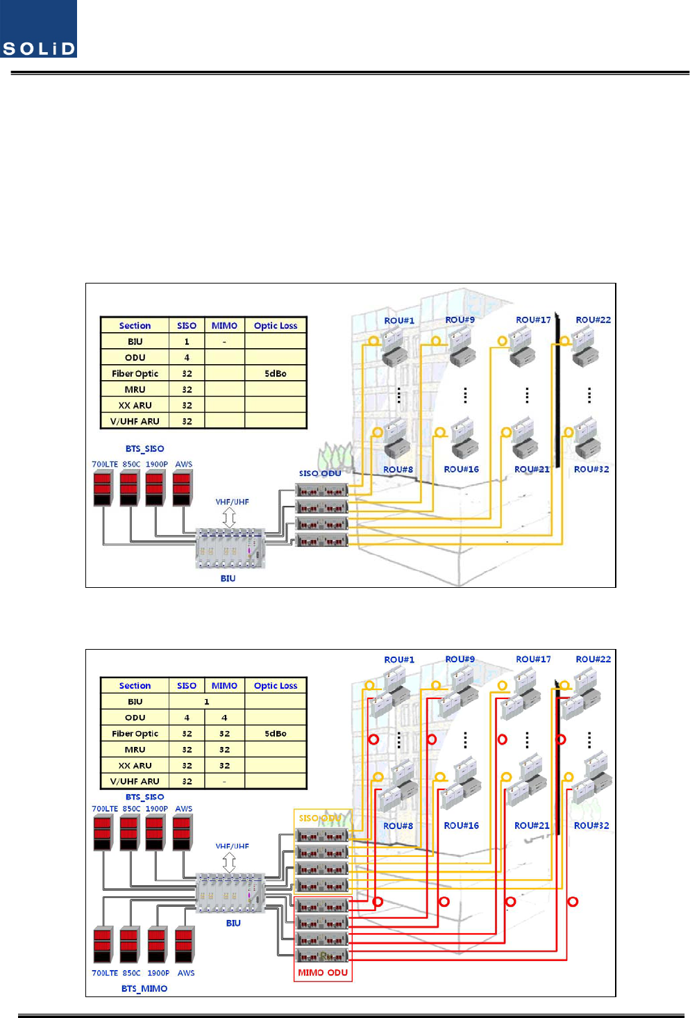
TheBIUhastwolayerwhichsupportbothSISOandMIMOconfigurationusingseparateopticalfiber
cable.Fig2.1showsbasicsystemtopologyforSISO
Figure1.1–BasicsystemtopologysupportingSISOconfiguration

Confidential&Proprietary17/115 SC‐DAS
Figure2.2–BasicsystemtopologysupportingMIMOconfiguration
AsshownatFig.’s2.1and2.2,onestrandoffiberisneededforSISOconfigurationbuttwostrands
areneededforMIMOcofigurationwhenconnectedwithanROU.Applicationsrequiringupto
32ROU’sforSISOarepossiblewithoneBIU.EachSISOROUwillrequireanadditionalstrandof
fiberandanadditional32ROU’scanbeaddedtothesamesystemforMIMOapplications.MIMO
requires2strandsoffiberperROUaswellasMIMOspecificODU’s.
Confidential&Proprietary18/115 SC‐DAS
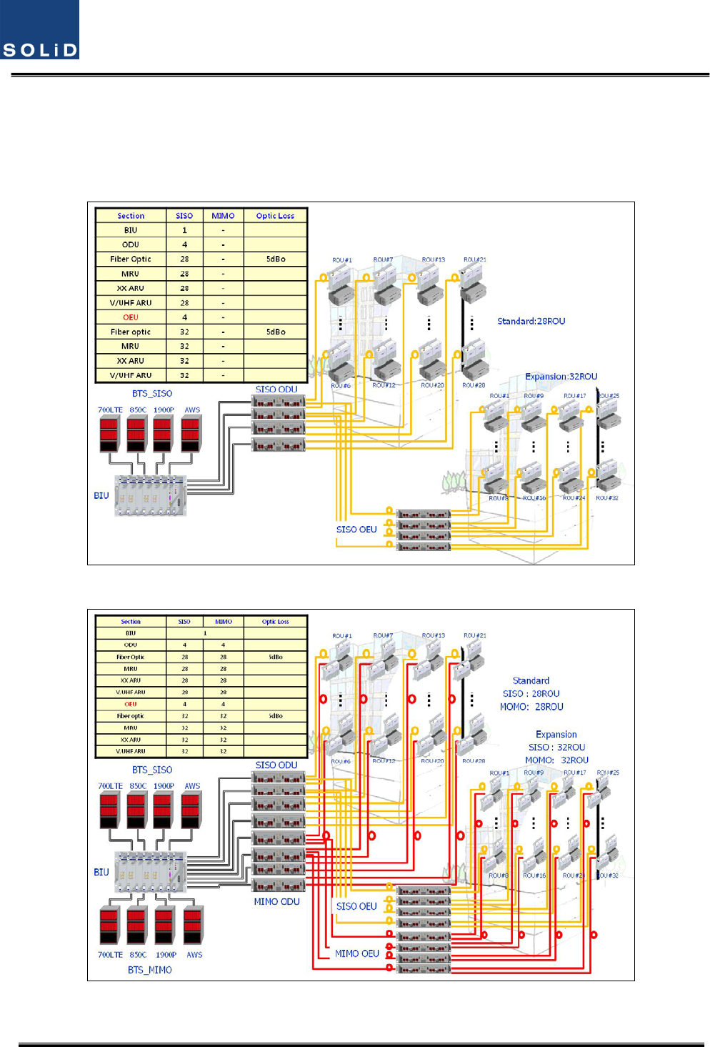
Toreducenumberofopticalcablesbetweenmulti‐buildingapplications,wecanutilizethe
OEU(OpticalExpansionUnit)
Fig2.3showsexpansionsystemtopologysupportingSISOconfigurationusingOEUs
Figure2.3–ExpansionsystemtopologysupportingSISOconfiguration
Figure2.4–ExpansionsystemtopologysupportingMIMOconfiguration

Confidential&Proprietary19/115 SC‐DAS
Fig2.4showsexpansionsystemtopologysupportingMIMOconfigurationusingOEU
Section3
SystemSpecifications
3.1Systemspecifications
3.1.1PhysicalSpecifications
3.1.2OpticwavelengthandLaserpower
3.1.3Environmentalspecifications
3.1.4Availablefrequencybands
3.1.5BandSpecifications

Confidential&Proprietary20/115 SC‐DAS
3.1 Systemspecifications
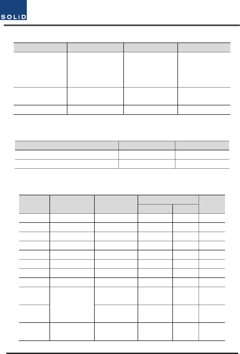
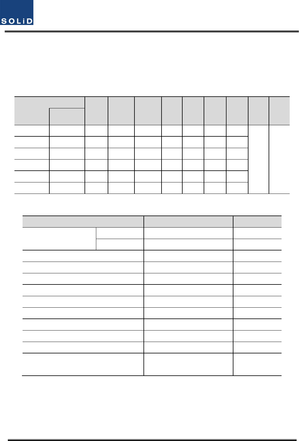
3.1.1 PhysicalSpecifications
ParameterBIUODUOEUMRUARU
RFConnectors4SMApairs(TX,RX)
perMDBU2SMA‐
1N‐type
2SMA:optical
2SMA:RF
2SMA:optical
2SMA:RF
ExternalAlarm
connector
(Drycontacts)
TB:4pcsforoutput
TB:3pcsforinput
‐ ‐ ‐ ‐
SerialInterface
connector1USB(B)type 1USB(B)type1USB(B)type1USB(B)type
Fiberconnector‐ 8pcs,SC/APCfor
ROU
1SC/APCforODU
8SC/APCforROU1SC/APCforODU‐
LEDAlarmand
StatusIndicator
MDBUStatus
z Powerstatus
z ALMstatus
MCPU
z Powerstatus
z TXComm
z RXComm
z ALMstatus
MPSU
z Powerstatus
z DCALMstatus
DOU1Status
z LDstatus
z PD1/2/3/4
status
DOU2Status
z LDstatus
z PD1/2/3/4
status
EWDMStatus
z LDstatus
z PDstatus
DOU1Status
z LDstatus
z PD1/2/3/4
status
DOU2Status
z LDstatus
z PD1/2/3/4
status
Systemstatus
z Powerstatus
z TX1Comm
z RX1Comm
z TX2Comm
z RX2Comm
z ALMstatus
Systemstatus
z Powerstatus
z TXComm
z RXComm
z ALMstatus
z Optstatus
Systemstatus
z Powerstatus
z TXComm
z RXComm
z ALMstatus
ACPower‐ ‐
NormalRange:120VAC
50/60Hz
Operatingrange
108~132VAC,50/60Hz
Sametoleftside
DCPower
Normalrange:‐48
VDC
Operatingrange:
‐40.8~‐57.6VDC
BeprovidedbyBIU
Normal:‐48VDC
Operatingrange:
‐40.8~‐57.6VDC
Sametoleftside
Power
consumption
SISOMode:162W
(IncludingSISOODU
4EA)
MIMOMode:315W
(IncludingSISOODU
4EA+MIMOODU
4EA)
28W
(Including
DOU2EA)
40W
(IncludingDOU2EA)
MRU1900P+850C:50W
MRU1900P:45W
MRU700LTE+AWS:50W
ARU700LTE+AWS:40W
ARU900I+800I:44W
Enclosure
Dimensions
482.6(19”)x
221.5(5U)x450
482.6(19”)x
43.6(1U)x450
482.6(19”)
x88.1(2U)x450300x200x258300x200x258
Weight[FullLoad]26.2Kg6Kg9.6Kg6.6Kg~7.1Kg6.8Kg
Confidential&Proprietary21/115 SC‐DAS
3.1.2 OpticalwavelengthandLaserpower
ParameterODUOEUROU
OpticalWavelength
TX:1310nm
RX:1550nm
Westoptic
TX:1550nm,RX:1310nm
Eastoptic
TX:1310nm,RX:1550nm
TX:1550nm
RX:1310nm
Outputpower1.5dBm±1dBmtoROU,OEU
1dBm±1dBmtoROU
7dBm±1dBmtoODU
7dBm±1dBmtoODU
Returnloss<45dB<45dB<45dB
3.1.3 Environmentalspecifications
ParameterBIU,ODU,OEUROU/AOR
OperatingTemperature‐10to+50°C‐10to+50°C
OperatingHumidity,noncondensing‐ 5%to90%
3.1.4 AvailableFrequencyBands
Standard UnitnamingDescription
Frequencyrange
Status
TX(MHz)RX(MHz)
iDEN700PSPublicsafety763to775793to805Infuture
iDEN800PSPublicsafety851to869806to824Completed
Cellular850CCellular869to894824to849Completed
iDEN900ISMR935to940896to901Completed
Paging900PAPaging929to930896to902Infuture
PCS1900PPCS1930to19951850to1915Completed
AWS‐1AWS‐1AWS‐12110to21551710to1755Completed
VHFVHFPublicsafety136to174136to174Infuture
UHF
UHF
Publicsafety(Band1)
396to450
450to512
396to450
450to512
Infuture
E‐UHFPublicsafety(Band2)
380to434
434to496
380to434
434to496
Infuture
LTE700LTELongTermEvolution728to756
698to716
777to787
Completed
Confidential&Proprietary22/115 SC‐DAS
3.1.5 BandSpecifications
SC‐DASplatformallowsmanybandcombinationsaswellasdifferentoutputpowerlevels
withinthebanddependingonthecombination.
1)Outputpowerlevel
BelowtableshowsOutputpowerlevelasafunctionofbandcombination
BandCombinations
700PS
700LTE
800PS/I
850C
900I
1900P
AWSVHFUHF
MRUARU
1900P+850C700LTE+AWS
‐ 24dBm‐24dBm
‐ 28dBm
28dBm
24dBm24dBm
1900P900I+800I‐ ‐ 26dBm‐26dBm
31dBm
‐
700LTE+AWS‐ ‐28dBm‐ ‐ ‐ ‐28dBm‐
1900P+AWS‐ ‐ ‐ ‐‐‐30dBm
30dBm
1900P+850C700PS+800PS
21dBm‐ 21dBm21dBm
‐ 30dBm
‐
700PS+800PS900I+800I21dBm‐ 21dBm21dBm
‐ ‐
2)GeneralSpecifications
ParameterSpecificationsRemark
GainControlrange
TX25dB/step1dBROU
RX20dB/step1dBBIU
TXinputpower‐20dBm~+10dBm
SpuriousEmission<‐13dBm
OpticalLinkAGC>10dB
VSWR1.8:1
Pass‐bandRipple4dBp‐p
MaxopticalLoss5dBo
Opticalwavelength1310nm/1550nmwithWDM
RXoutputpower0dBm
RXinputpower‐50dBmMax
NoiseFigure<8dB
Excluding700PS,
800PS

Confidential&Proprietary23/115 SC‐DAS
Section4
SystemConfigurationandFunctions
4.1BIU(BTSInterfaceUnit)
4.2ODU(OpticdistributionUnit)
4.3OEU(OpticExpansionUnit
4.4ROU(RemoteOpticUnit)
Confidential&Proprietary24/115 SC‐DAS
4.1 BIU(BTSInterfaceUnit)
TheBIUreceivessignalsfromtheBTSorBDAthroughcoaxialcableandtransmitstofour
ODUs(OpticDistributionUnit).andTheBIUseparatesRXsignalsreceivedfromODUs
accordingtotheirfrequencyband.
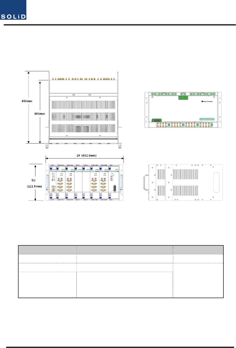
Figure4.1–BIUfrontandsideviews
4.1.1 BIUSpecifications
ItemSpec.Remark
Size482.6(19”)x221.5(5U)x450mm
Weight26Kg
FullLoad
Powerconsumption
SISOMode:168W(IncludingSISOODU4EA)
MIMOMode:315W(IncludingSISOODU
4EA+MIMOODU4EA)
Confidential&Proprietary25/115 SC‐DAS
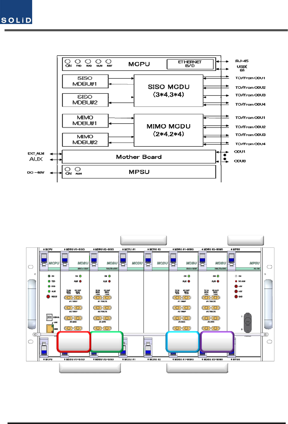
4.1.2 BIUblockdiagram
Figure4.2–BIUblockdiagram
4.1.3 BIUassemblies
MDBU
#2
MDBU
#1 MDBU
#3 MDBU
#4
SISO Side MIMO Side
MCDU’s MPSU
Figure4.3–BIUmountingdiagram

Confidential&Proprietary26/115 SC‐DAS
No.UnitDescriptionRemark
1MDBU
MainDriveBTSUnit
Amplify&adjustdownlinkRFsignal
Amplify&adjustuplinkRFsignal
Max4EA
2MCDU
MainCom/DivUnit
Combine3EAdownlinksignalanddivide4EAsignaltoODU
Combine4EAuplinksignalanddivide3EAsignaltoMDBU
SupportVHF/UHFinterfaceport
3MCPU
MainCentralProcessorUnit
Controlandmonitoringsystemstatus
ControlandmonitoringwithUSB(B)
Allowsaccesstoupper‐levelnetworkthroughGSMorEthernet
4MPSUMainPowerSupplyUnit
Inputpower:DC‐48V,Outputpower:9V,6V
5M/B
MotherBoard
Providesignalinterfaceandpowerforeachunit
Providefourportsfordrycontactoutput
Providethreeportsforinput
ProvidetwoAuxportsforfutureusage
6Shelf19inch,5U
4.1.4 SubAssemblyDescription
1)MainDriveBTSUnit(MDBU)
MDBUdeliversTXsignalsfromtheBTSorBDAtorelateddevicesaswellasdeliversRXsignalsfrom
thesedevicestotheBTSorBDA.ThisunitalsomonitorsTXinputlevel.UsingtheinputAGCfunction,
itautomaticallyadjustsinputATTaccordingtoinputpower.ItalsohasanATTtoadjustRXgain.The
MDBUvariesperfrequencybandtoincludingthefollowing:
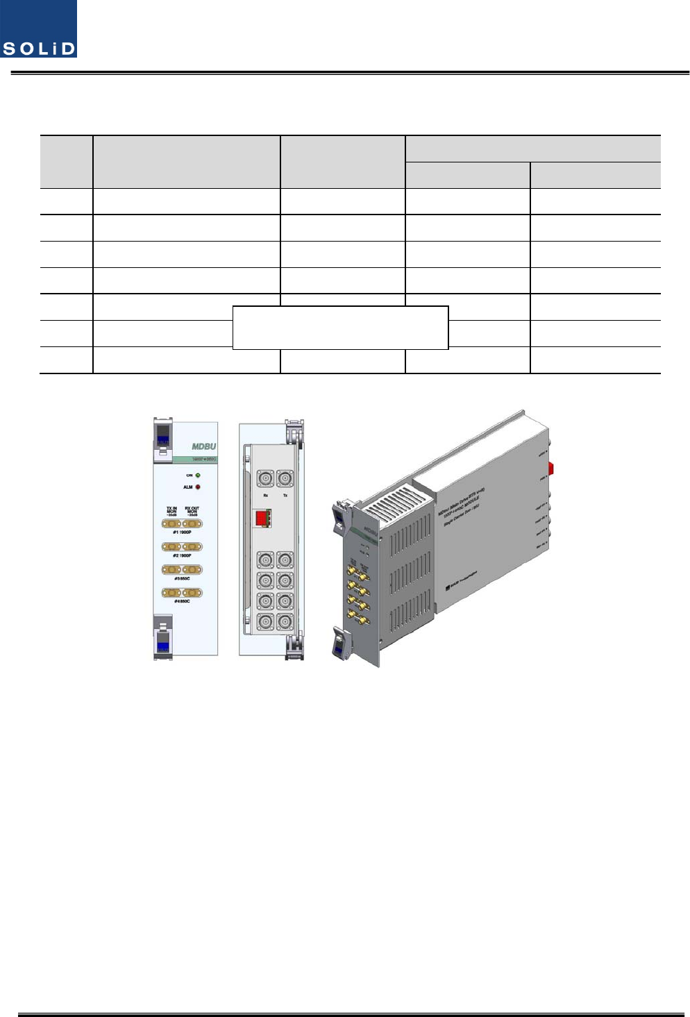
Confidential&Proprietary27/115 SC‐DAS
NoUnitnamingDescription
In/outRFPort
TXRX
11900P+850CDualBand4Port4Port
2700LTE+AWS‐1DualBand4Port4Port
31900PSingleBand2Port2Port
4900I+800IDualBand4Port4Port
51900P+AWS‐1DualBand4Port4Port
6700PS+800PSDualBand4Port4Port
7900IDualBand2Port2Port
Figure4.4–MDBUataglance
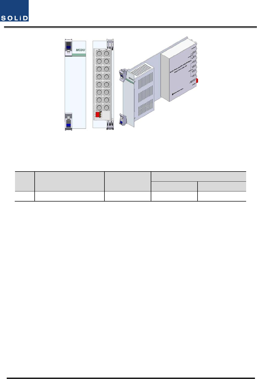
2)MainCom/DivUnit(MCDU)
MCDUcombinesTXsignalsthataredeliveredfromMDBUperfrequencybandanddeliversthemto
fourODUs.ItalsocombinesRXsignalsfromuptofourODUsandsendsthemtouptofour
MDBUs.TheunithasaporttointerfacewithVHF&UHFsignals.IthasanATTforinputmonitoringand
inputcontrol.
TheunithasareservedportforfutureusagesuchasLMUinterface,additiveMDBUinterface,etc,
On the loadmap
Confidential&Proprietary28/115 SC‐DAS
Figure4.5–MCDUataglance
VHF+UHFfrequencybandincludesthefollowing:foruseinfuture
NoUnitnamingDescription
In/outRFPort
TXRX
1VHF+UHFDualBand1Port1Port
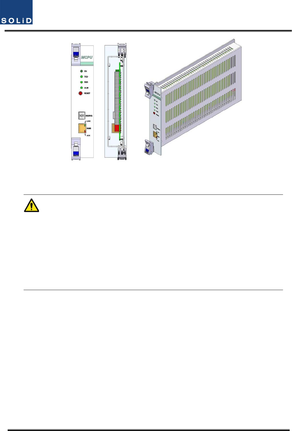
3)MainCentralProcessorUnit(MCPU)
MCPUcaninquireandcontrolthestateofthemodulesthatareinstalledintheBIU.
ThisunitcaninquireandcontrolthestateofuptofourODUs.Throughcommunication,italsocan
inquireandcontrolROUsthatareconnected.
Inaddition,theunithasUSB(B)portforlocalmonitoringsothatitcaninquireandcontrolstateof
devicesthroughaPC.Onthefrontpanel,ithascommunicationLEDindicatorstocheck
communicationstatewithROU.ItalsohasALMLEDindicatorstoshowwhetheradeviceisfaulty.
Foraccesstouppernetwork,ithasaporttoinsertanEthernetportandGSMmodeminit.
Confidential&Proprietary29/115 SC‐DAS
Figure4.6–MCPUataglance
IntheMainCentralProcessorUnit,alithiumbatteryisinstalledforRTC(RealTimeControl)function.
CAUTION
RISKOFEXPLOSIONMAYOCCURIFBATTERYISREPLACEDBYANINCORRECTTYPE
DIPOSEOFUSEDBATTERIESACCORDINGTOTHEINSTRUCTIONS
[INSTRUCTION]
Theequipmentandaccessoriesincludinginnerlithiumbatteryaretobedisposedofsafelyafterthe
lifespanofthemaccordingtothenationalregulation.Donotattempttoreplacethelithiumbattery
unlessauthorizedbyaqualifiedservicepersonnel,toavoidanyriskofexplosion.
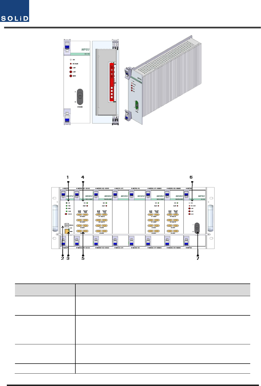
4)MainPowerSupplyUnit(MPSU)
TheMPSUtakesa‐48Vinputandoutputs+6Vand+9VDCpower.
Onthefrontpanel,thisunithasanoutputtestportanditalsohasDCALMLEDIndicatortoshow
faultyoutput.
Confidential&Proprietary30/115 SC‐DAS
Figure4.7–MPSUataglance
4.1.5 BIUfront/rearpaneloverview
1)Frontpanel
Figure4.8–BIUfrontpanelview
ItemDescription
1.AlarmLED&ResetCommunicationstatewithdevices,alarmstatusofthesystemandreset
switch
2.DEBUG(USBB)
USBportforcommunicationanddiagnosisofdevicesthroughPC/laptop
Thisequipmentisforindooruseonlyandallthecommunicationwiringsare
limitedtoindooruseaswell.
3.NMS(Ethernetport)Ethernetportforuppernetwork
ThesupportingnetworkmodeisUDPprotocol
4.MDBULEDLEDtoshowwhetherMDBUisinstalledandisoperatingproperly

Confidential&Proprietary31/115 SC‐DAS
5.RFMonitorPort20dBCouplingcomparedwithTXInputLevel
20dBCouplingcomparedwithRXOutputLevel
6.PwrTestPort&ALMOutputDCpowertestportandALMLEDtoshowabnormalstate,ifany
7.PowerswitchPowerON/OFFswitch
Confidential&Proprietary32/115 SC‐DAS
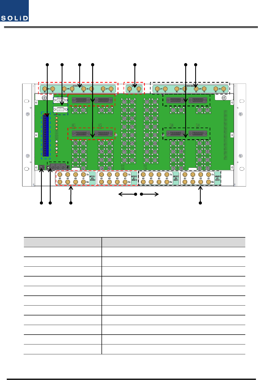
2)Rearpanel
Figure4.9–Rearpanelview
ItemDescription
1.DCInputPortInputterminalforDC‐48V
2.ExternalALMPortInput/outputterminalfordrycontact
3.GNDPortSystemgroundterminal
4.AUXI/OPortReservedPortforfutureuses
5.MIMOODUI/OPortRFsignalinterfaceterminalforODU
6.MIMOODUsignalPortPowerandsignalinterfaceterminalforODU
7.MIMOBTS/BDAI/OPortInput/outputinterfaceterminalofBTS/BDA
8.V/UHFI/OPortRFsignalinterfaceterminalofVHF&UHF
9.SISOODUI/OPortRFsignalinterfaceterminalforODU
10.SISOODUsignalPortPowerandsignalinterfaceterminalforODU
11.SISOBTS/BDAI/OPortInput/outputinterfaceterminalofBTS/BDA
1
5
8 9 6 10
SISO SIDE MIMO SIDE
3 4
7 11 2
Confidential&Proprietary33/115 SC‐DAS
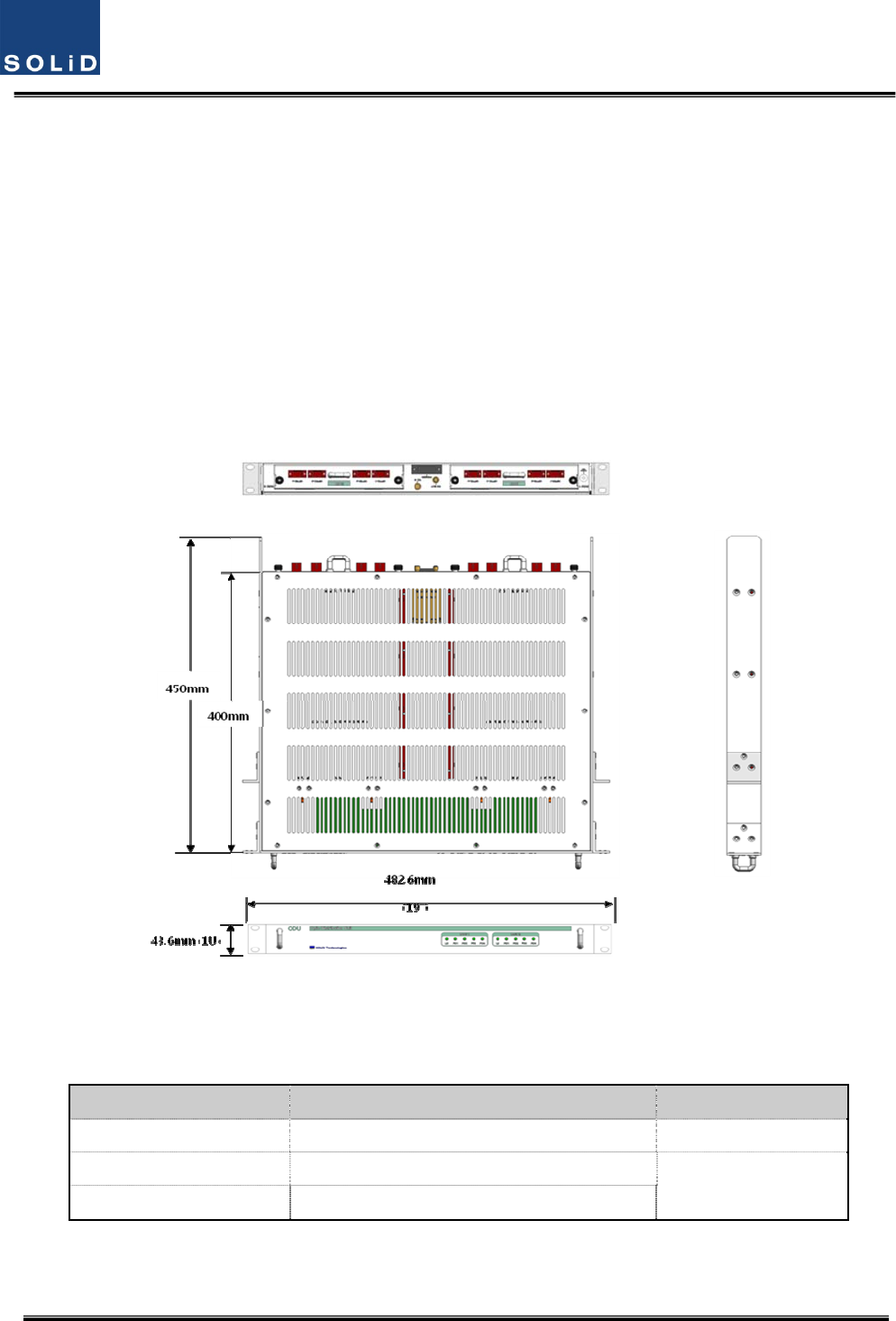
4.2 ODU(OpticdistributionUnit)
ODUreceivesTXRFsignalsfromupperBIUandconvertsthemintoopticalsignals.Theoptical
signalsaresenttoROUthroughopticalcables.ThisunitconvertsopticalsignalsfromROUintoRF
signalsandsendstheconvertedsignalstoBIU.
ForeachshelfoftheODU,uptotwoDOUs(DonorOpticUnit)canbeinstalledinit.
OneDOUissupportedwithfouropticalports.Therefore,oneODUcanbeconnectedwitheight
ROUs.
UptofourODUscanbeconnectedwithBIUeachSISOandMIMOpath
Figure4.10–ODUataglance
4.2.1 ODUspecifications
ItemSpec.Remark
Size482.6(19”)x43.6(1U)x450mm
Weight6kg
FullLoad
Powerconsumption27W
Confidential&Proprietary34/115 SC‐DAS
4.2.2 ODUblockdiagram
Figure4.11–ODUblockdiagram
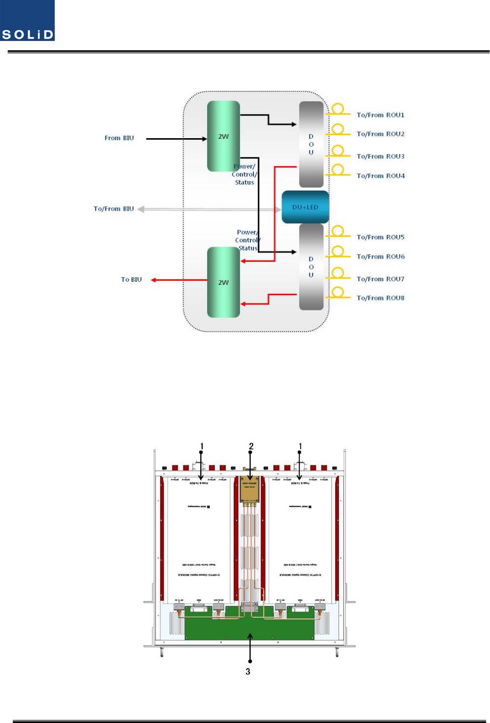
4.2.3 ODUassemblies
Figure4.12–ODUInternalView

Confidential&Proprietary35/115 SC‐DAS
No.UnitDescriptionRemark
1DOU
DonorOpticUnit
ConvertsTXRFsignalsintoopticalsignals;
ConvertsRXopticalsignalsintoRFsignals;
ProvidesuptofouropticalportsperDOU
Max2ea.
22W
2WayDivider
DividesTXRFsignalsintotwo;
CombinestwoRXRFsignalsintoone
3DUDistributionUnit
DistributespowerandsignalstoDOU
4Shelf19”rack,1RU
5Accessories25PINDSUB,Maletofemale1pcs
RFCoaxialCableAssembly2pcs
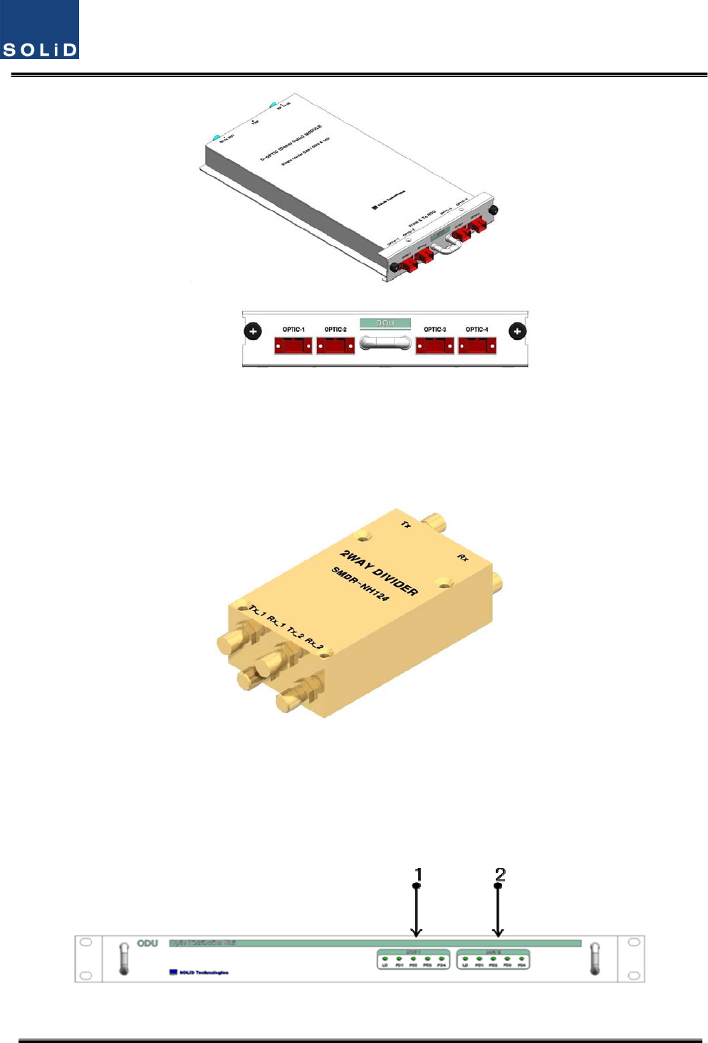
4.2.4 SubAssemblydescription
1)DonorOpticUnit(DOU)
TheDOUperformstheRFtoopticalconversionofTXsignalsaswellastheopticaltoRFconversion
ofRXsignals.
Usinganopticalsplitter,thisunitdividesopticalsignalsfromaLaserDiodeintofourandthen
distributesthemtoeachopticalport.WithatotaloffourPhotoDiodesinRX,theDOUperformsthe
opticaltoRFconversionofsignalsreceivedfromeachopticalport.Inaddition,theunitisequipped
withanATTtocompensateforopticallossinthefiberorfiberconnectors.
SinceisusesaWDM,itusesonlyonestrandoffiberforeachROUitconnectsto.
WithinternalFSKmodem,itwillallowoperationfromaremotesite.
Confidential&Proprietary36/115 SC‐DAS
Figure4.13–DOUataglance
2)2WayDivider(2W)
The2waydividerisequippedwithtwo2‐waysplittersinasinglehousingandthesplittersworkfor
TX/RXsignals,respectively.
Designedinbroadbandtype,thedividercombinesandsplitssignalsfrom/totheBIU
Figure4.14–2WayDividerataglance
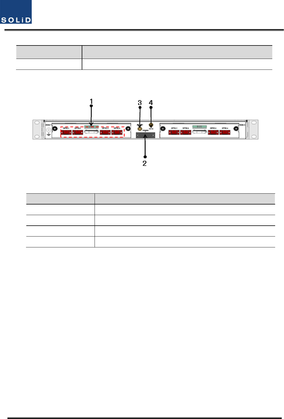
4.2.5 ODUfront/rearpaneloverview
1)Frontpanel
Figure4.15–ODUfrontpanelview
Confidential&Proprietary37/115 SC‐DAS
ItemDescription
1,2LEDindicatortocheckforfaultyDOUmodule.
2)Rearpanel
Figure4.16–ODURearpanelview
ItemDescription
1.OpticPortSC/APCopticalconnectorterminal;useoneopticalcableperROU.
2.DCI/OPortTerminalforpowerandstatevalues
3.RXRFPortRXRFsignalinterfaceterminal
4.TXRFPortTXRFsignalinterfaceterminal
Confidential&Proprietary38/115 SC‐DAS
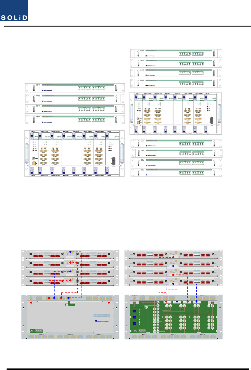
4.2.6 ODUInterfacewithBIU
SISOConfigurationMIMOConfiguration
Figure4.17BIU/ODUinterface
ForSISOconfiguration,uptofourODUscanbestacked.abovethetopoftheBIU.
ForMIMOconfiguaration,uptoeightODUscanbestackedabove/belowtheBIU.
Inthiscase,itisrecommendedtoleavea1RUspacebetweenBIUandtheODUsotherwiseheatfrom
BIUmaydegradetheperformanceoftheODUs,
Figure4.18–BIU/ODUInterfacerearview
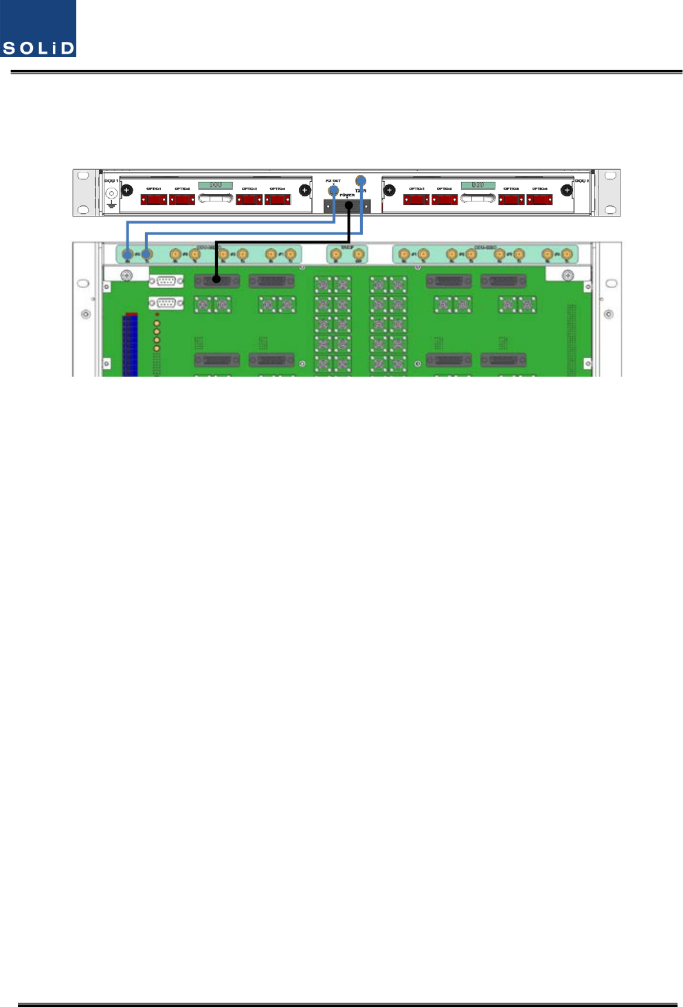
Confidential&Proprietary39/115 SC‐DAS
Asshowninthefigurebelow,connectonecoaxialcableforTXandanothercoaxialcableforRXwith
correspondingportsattherearofBIU.Forpowersupplyandcommunication,connect25PinD‐Sub
Connectorcabletothecorrespondingport.
Figure4.19–BIU/ODUinterfacedetails
Confidential&Proprietary40/115 SC‐DAS
4.3 OEU(OpticExpansionUnit)
OEUismainlyusedtoremotelydeliversignalsforCampusclusters.Attheupperpart,thisunit
combineswithODUandreceivesTXopticalsignalstoconvertthemintoRFsignals.Then,it
regeneratesthesignalstosecureSNRandconvertsthemintoopticalsignals.Thesignalsaresentto
ROUthroughopticalcables.WhenitreceivesRXopticalsignalsfromROU,theunitconvertsthem
intoRFsignalstoregeneratethesignalsandthenconvertsthemintoopticalsignalstosendthemto
ODU.
InOEU,oneshelfcanbeequippedwithuptotwoDOUs.TheDOUisthesameasthemoduleused
forODU.UptofourOEUscanbeconnectedwithODU.
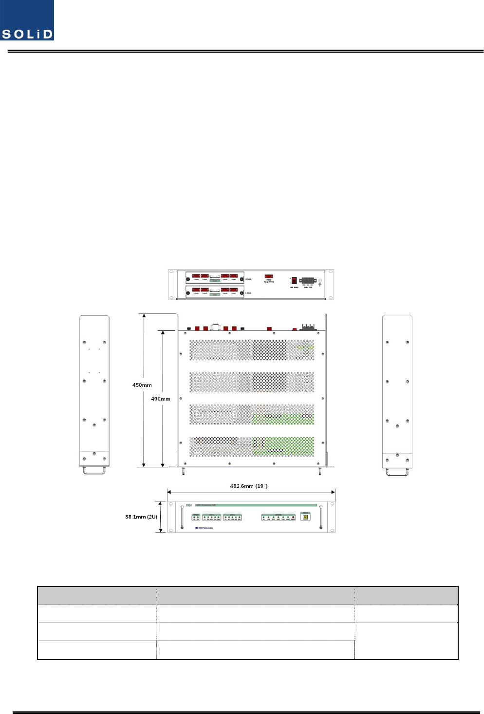
Figure4.20–OEUataglance
4.3.1 SpecificationsofOEU
ItemSpec.Remark
Size482.6(19”)x88.1(2RU)x450mm
Weight9.5kg
FullLoad
Powerconsumption40W
Confidential&Proprietary41/115 SC‐DAS
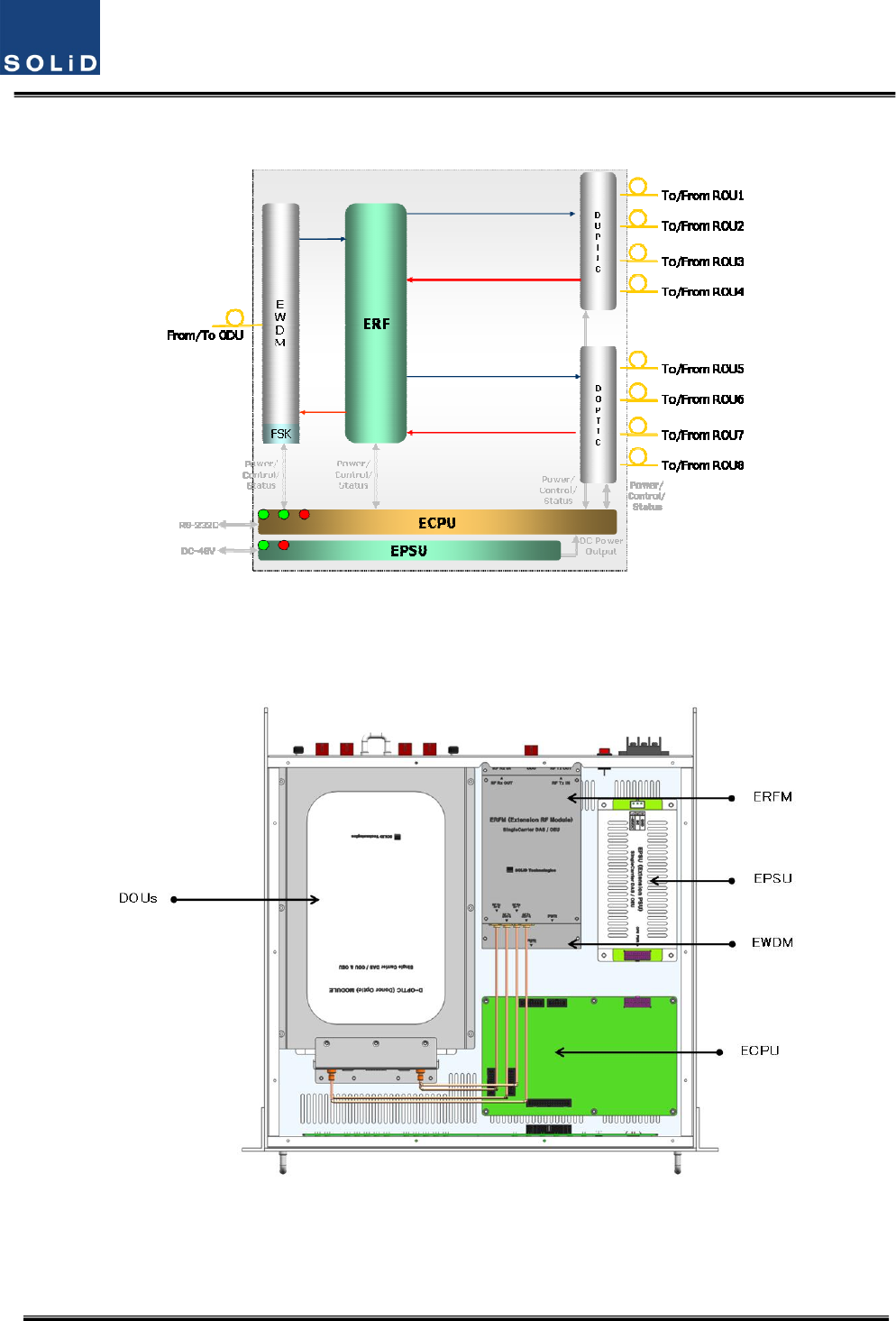
4.3.2 OEUblockdiagram
Figure4.21–OEUblockdiagram
4.3.3 OEUassemblies
Figure4.22–OEUinternalview
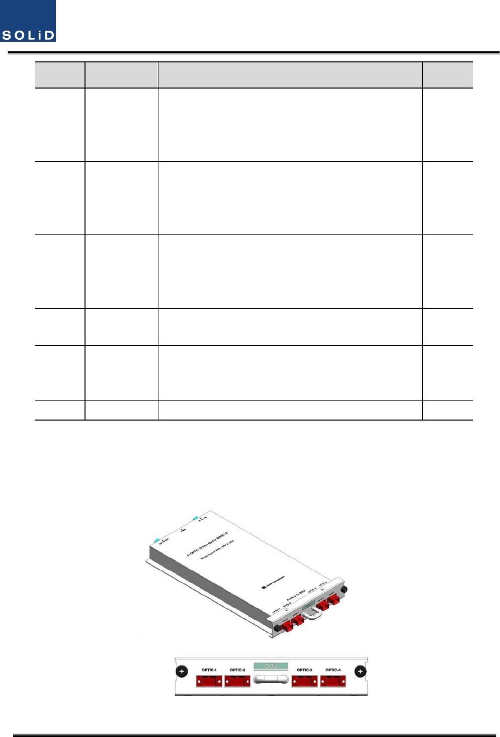
Confidential&Proprietary42/115 SC‐DAS
No.UnitDescriptionRemark
1DOU
DonorOpticUnit
ConvertTXRFsignalsintoopticalsignals;
ConvertRXopticalsignalsintoRFsignals;
ProvideuptofouropticalportsperDOU
Max2ea.
2EWDM
ExpansionWavelengthDivisionMultiplexer
ConvertTXopticalsignalsintoRFsignals;
ConvertRXRFsignalsintoopticalsignals;
CompensatesforopticalcablelosswithODU
3ECPU
ExpansionCentralProcessorUnit
Controlandmonitoringsystemstatus
ControlandmonitoringwithRS232
RelaysstatevaluesofROUtoBIU
4EPSUExpansionPowerSupplyUnit
Inputpower:DC‐48V,Outputpower:9V,6V
5ERFM
ExpansionRadioFrequencyModule
RegenerateTXsignalsandtransmitFSKmodemsignals;
RegenerateRXsignalsandreceiveFSKmodemsignals
6Shelf19”rack,2RU
4.3.4 SubAssemblydescription
1)DonorOpticUnit(DOU)
TheDOUisthesameasthemoduleusedfortheODU.
Figure4.23–DOUataglance
Confidential&Proprietary43/115 SC‐DAS
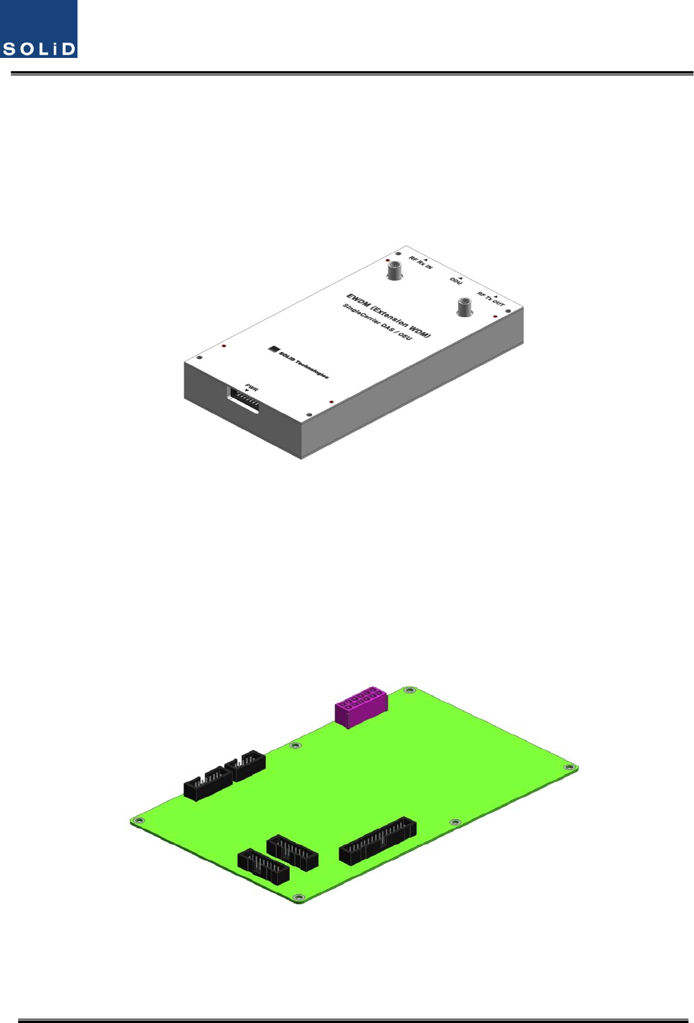
2)ExpansionWavelengthDivisionMultiplexer(EWDM)
EWDMmodulehandlestheopticaltoRFconversionofTXsignalsaswellastheRFtooptical
conversionofRXsignals.ThismultiplexercommunicateswiththeBIUusingthebuiltinFSKmodem.
ItalsohasanATTtocompensateforopticalcablelossbetweenODUs.
Finally,ithasinternalWDMsoitneedsonlyoneopticalcabletoworkwithanROU.
Figure4.24–EWDMataglance
3)ExpansionCentralProcessorUnit(ECPU)
ECPUcanqueryandcontrolthestateofmodulesinstalledintotheOEU.Thisunitsimultaneoulsy
communicateswiththeBIUandtheROUaswellasactingascommunicationbridgebetweenBIUand
ROU.
Inaddition,theunithasaUSBportforlocalcommunicationwhichenablesqueryandcontrolof
devicesthorughaPC.Atthefrontpanel,communicationLEDindicatorindicatescommunication
withupperBIUandlowerROU.ItalsohasanALMLEDindicatortoshowfault.
Figure4.25–ECPUataglance
4)ExpansionRadioFrequencyModule(ERFM)
ERFMrepairsSignaltoNoisedegradedbyopticalmodules.
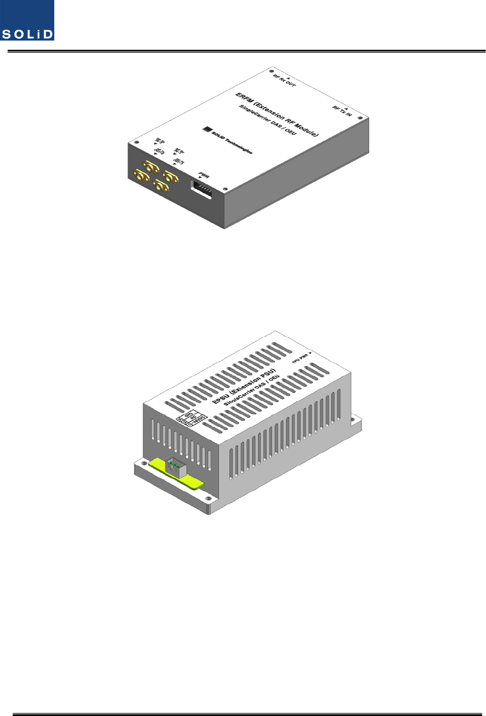
Confidential&Proprietary44/115 SC‐DAS
Figure4.26–ERFMataglance
5)ExpansionPowerSupplyUnit(EPSU)
AsDC/DCConverter,theEPSUreceives‐48VDCinputandprovides+9Vand+6VofDCpower
requiredforOEU.
Figure4.27–EPSUataglance
Confidential&Proprietary45/115 SC‐DAS
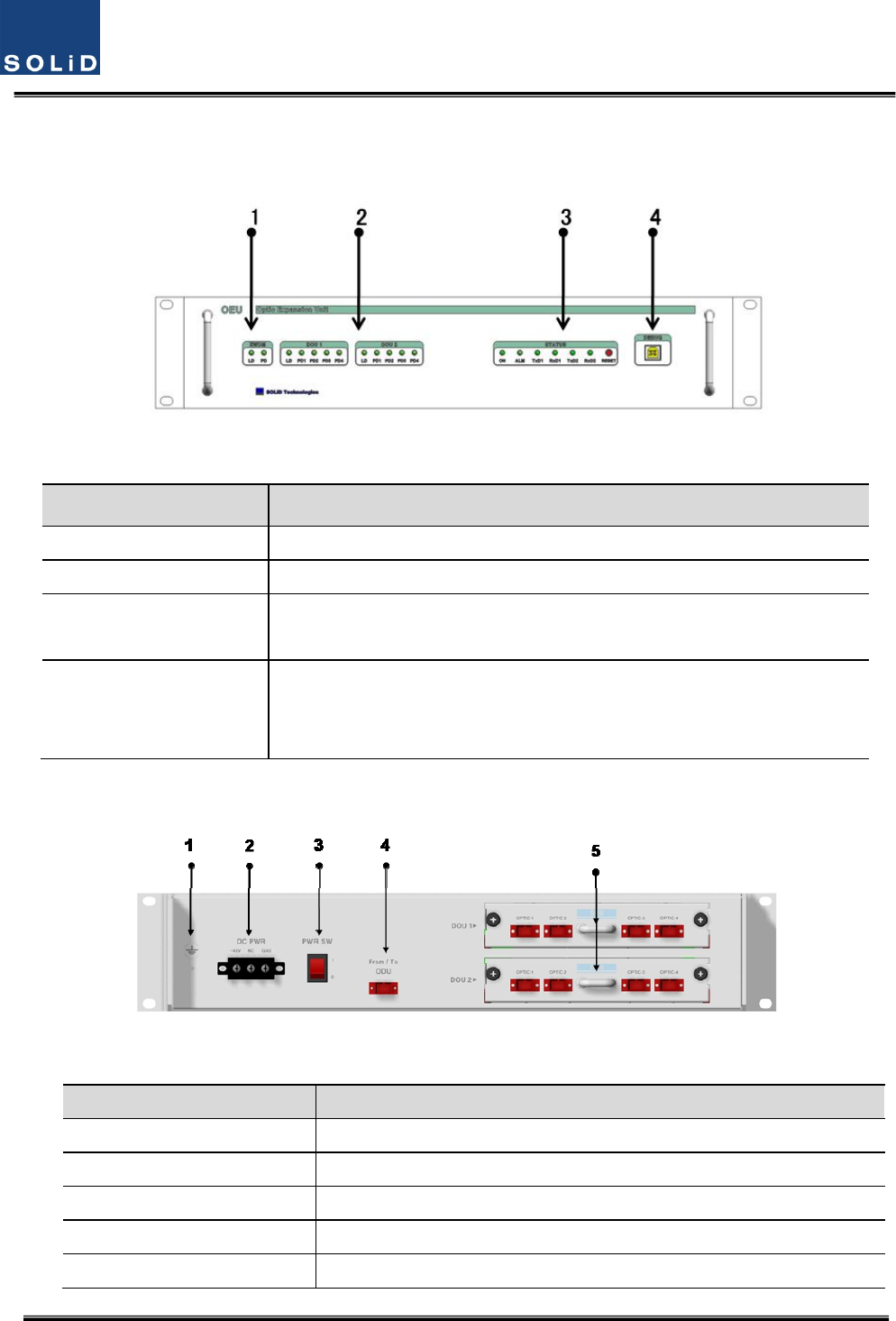
4.3.5 OEUfront/rearpaneloverview
1) Frontpanel
Figure4.28–OEUfrontpanelview
ItemDescription
1.EWDMLEDLEDindicatortocheckEWDMstatetoseeifitisabnormal
2.DOULEDLEDindicatortocheckDOUmodulestatetoseeifitisabnormal
3.SystemLEDandResetCommunicationstatewithdevices,alarmstatusofthesystemandreset
switch
4.NMS(USBPort)
USBportforcommunicationanddiagnosisofdevicesthroughPC/laptop.
Thisequipmentisforindooruseonlyandallthecommunicationwiringsare
limitedtoindooruseaswell.
2)Rearpanel
Figure4.29–Rearpanelview
ItemDescription
1.GNDPortTerminalforsystemground
2.DCInputPortInputterminalforDC‐48V
3.powerswitchPowerON/OFFswitch
4.To/FromODUOpticPortSC/APCopticalconnectorterminal
5.To/FromROUOpticPortSC/APCopticalconnectorterminal;useoneopticalcableperROU.
Confidential&Proprietary46/115 SC‐DAS
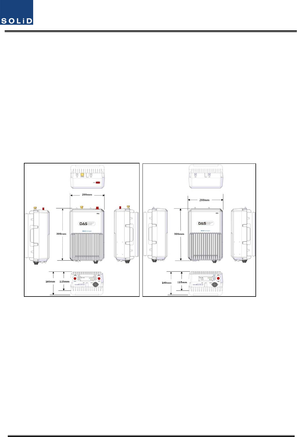
4.4 ROU(RemoteOpticUnit)
TheROUconsistsoftwounits:theMRU(MainRemoteUnit)andtheARU(AddonRemoteUnit).The
ROUisconsideredthecombinationofMRUandARU.
TheMRUreceivesTXopticalsignalsfromtheODUortheOEUandconvertsthemintoRFsignals.
TheconvertedRFsignalsareamplifiedthroughaHighPowerAmpinacorrespondingRU,combined
withtheMultiplexerandtransmittedouttheantennaport.
TheROUreceivesRXsignalsthroughtheantennaport,filtersout‐of‐bandsignalsinacorresponding
RUandsendstheresultstoRemoteOpticModuletomakeRFtoopticalconversionofthem.After
converted,thesignalsaresenttoaupperdevice(theODUorOEU).
TheMRUandARUhaveamaximumof2bands.
ThemaindifferencebetweenanMRUanARUisthepresenceofanopticalmodule.
(a)MRU(b)ARU
Figure4.30–ROUataglance

Confidential&Proprietary47/115 SC‐DAS
4.4.1 ROUspecifications
ItemBandcombinationSize
(WxHxD)WeightPower
consumption
Remark
Band
Combination1
MRU1900P+850C
200x300x140
mm
6.6kg50W
Full
load
ARU700LTE+AWS‐16.8kg40W
Band
Combination2
MRU1900P6.5kg45W
ARU900I+800I6.7kg44W
Band
Combination2
MRU700LTE+AWS‐17.1kg50W
Band
Combination4
Tobedeveloped
Tobedeveloped
Confidential&Proprietary48/115 SC‐DAS
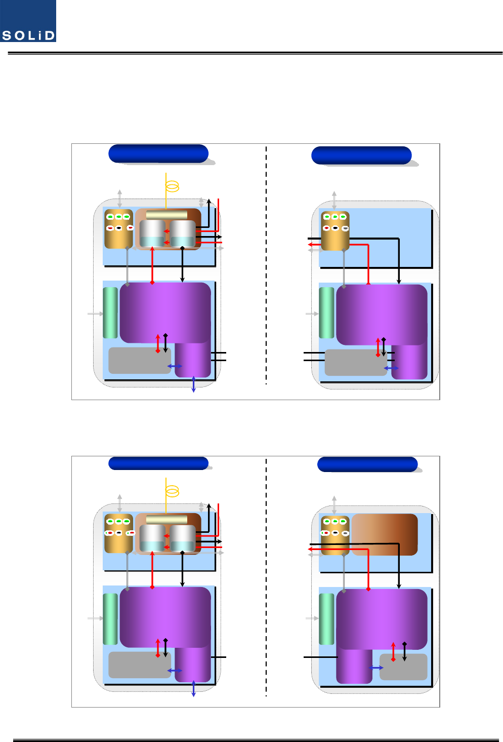
4.4.2 ROUblockdiagram
4.4.2.1 CombinationofMRU1900PCS+850C/ARU700LTE+AWS‐1
RCU
Cavity Filter
USB
(B type)
AC 120V
Or
DC -48V
Power/
Control/
Status
MRFM
ANT(N-Female)
EX_PORT
EX_PORT
RXD
Reset
ON TXD
ALM Opt
LOW
HIGH
From/To ODU
LD
FSK TX
SC/APC
V/UHF RX
ARU TX
WDM
PD
ARU RX
V/UHF TX
Power/
Control/
Status
EX_PORT
LOW
HIGH
MRU TX
MRU RX
USB
(B type)
FSK RX
RCU
Cavity Filter
ARFM
MRU 1900PCS+850C ARU 700LTE+AWS-1
RXD
Reset
ON TXD
ALM Opt
AC/
DC
Or
DC/
DC
AC/
DC
Or
DC/
DC
AC 120V
Or
DC -48V
Figure4.31–ROUblockdiagramforMRU1900PCS+850CandARU700LTE+AWS‐1
4.4.2.2 CombinationofMRU1900PCS/ARU900I+800I
RCU
1900P
Cavity Filter
USB
(B type)
Power/
Control/
Status
MRFM
ANT(N-Female)
EX_PORT
EX_PORT
RXD
Reset
ON TXD
ALM Opt
LOW
From/To ODU
LD
FSK TX
SC/APC
V/UHF TX
ARU TX
WDM
AC/
DC
Or
DC/
DC
PD
ARU RX
V/UHF RX
Power/
Control/
Status
EX_PORT
LOW
MRU TX
MRU RX
USB
(B type)
FSK RX
RCU
800I/900I
Cavity Filter
ARFM
1900P MRU 800I+900I ARU
AC/
DC
Or
DC/
DC
RXD
Reset
ON TXD
ALM Opt
OPT SIU
AC 120V
Or
DC -48V
AC 120V
Or
DC -48V
Figure4.32–ROUblockdiagramforMRU1900PCSandARU900I+800I
Confidential&Proprietary49/115 SC‐DAS
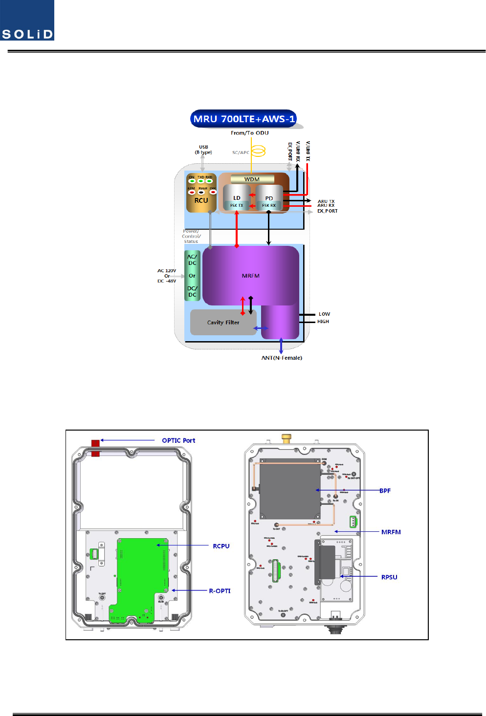
4.4.2.3 CombinationofMRU700LTE+AWS‐1
Figure4.33–ROUblockdiagramforMRU700LTE+AWS‐1
4.4.2.4 CombinationofMRU1900PCS+850C/ARU700LTE+AWS‐1
(a)MRU1900PCS+850C
Confidential&Proprietary50/115 SC‐DAS
(b)ARU700LTE+AWS‐1
Figure4.34–ROUinternalviewforMRU1900PCS+850CandARU700LTE+AWS‐1
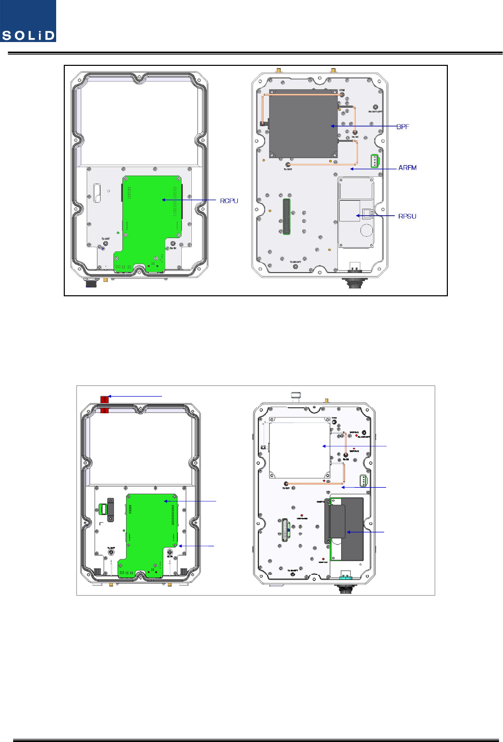
4.4.2.5 CombinationofMRU1900PCS/ARU900I+800I
BPF
MRFM
RPSU
RCPU
R-OPTIC
OPTIC Port
(a)MRU1900PCS
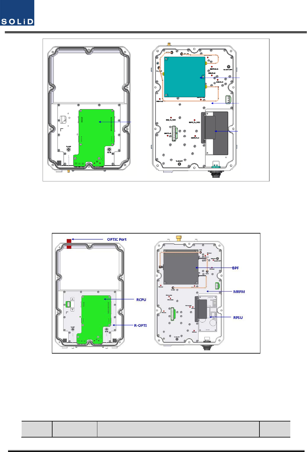
Confidential&Proprietary51/115 SC‐DAS
BPF
ARFM
RPSU
RCPU
(b)ARU900I+800I
Figure4.35–ROUinternalviewforMRU1900PCSandARU900I+800I
4.4.2.6 CombinationofMRU700LTE+AWS‐1
(a)MRU700LTE+AWS‐1
Figure4.36–ROUinternalviewforMRURU900I+800I
No.UnitDescriptionRemark

Confidential&Proprietary52/115 SC‐DAS
1MRFM/ARFM
+BPF
Main/AddonRFModule
FilterandheavyamplificationofTXsignals;
FilterandamplifyRXsignals;
RemoveothersignalsthroughBPF
2RPSU
RemotePowerSupplyUnit
Inputpower:DC‐48VorAC120V,Outputpower:25V
For120VinputofAC/DC;
For‐48VinputofDC/DC
3R‐OPT
RemoteOptic
MakeRFconversionofTXopticalsignals;
ConvertRXRFsignalsintoopticalsignals;
Compensatesopticallossinterval
CommunicateswithBIUorOEUthoughtheFSKmodem
4RCPU
RemoteCentralProcessorUnit
Controlssignalofeachunit
MonitorsBIU/ODU/OEUstatusthroughFSKmodem
communication
5Enclosure
EnableWallMount;
Checkifthesystemisnormal,throughthebottompanel
LED
Confidential&Proprietary53/115 SC‐DAS
4.4.3 SubAssemblydescription
1)MainRFModule/AddonRFModule(MRFM/ARFM)+BPF
WhenreceivingTXsignalsfromeachbandthroughR‐Opt,MRFM/AFRMfiltersthesignalsand
amplifiesthemwiththeHighPowerAmpifier.TheunitalsofiltersRXsignalsreceivedthroughthe
antennaportandamplifiesthemaslownoisetosendthesignalstoR‐Opt.
Intheunit,thereisanATTtoadjustgain.Thisdevicevariesforeachfrequencyband,includingthe
following:
NoCombinationUnitnamingDescription
BPF
CavityFilterCeramicFilter
1
MRU1900P+850CMRFM1900P+850C Dual.1900PCS850C
ARU700LTE+AWS‐1ARFM700LTE+AWS‐1Dual.700LTEAWS‐1
2
MRU1900PMRFM1900PSingle1900PCS‐
ARU900I+800IARFM900I+800IDual900IEN/800IDEN‐
3MRU700LTE+AWS‐1MRU700LTE+AWS‐1Dual.700LTEAWS‐1
4Tobedeveloped‐ ‐ ‐ ‐
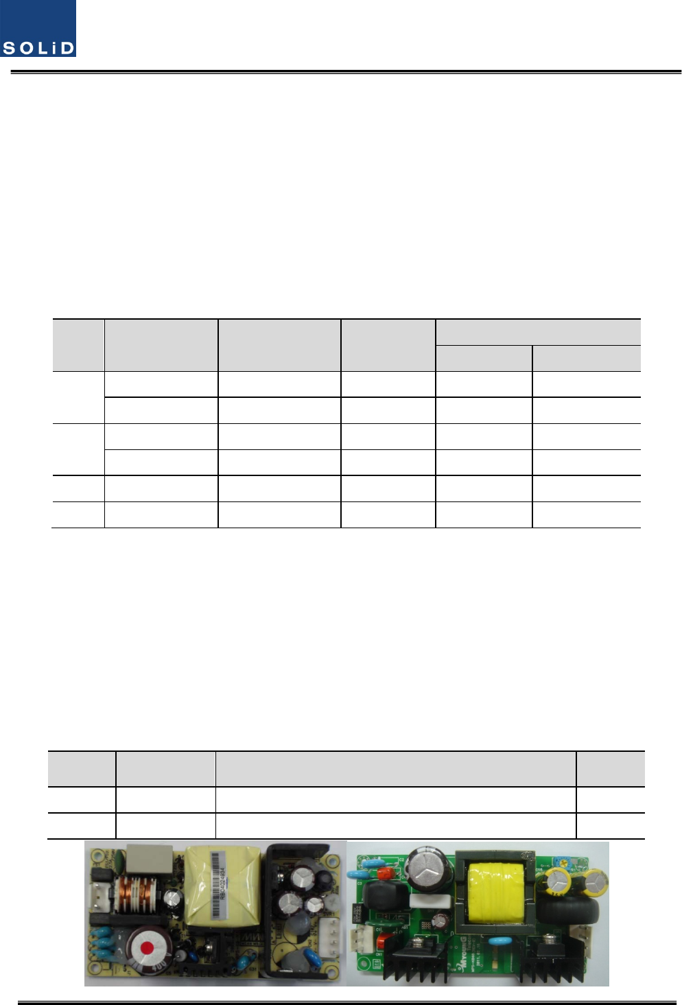
2)RemotePowerSupplyUnit(RPSU)
RPSUaccepts‐48VDCinput.Thisunitisconfigured2ways:theDC/DCtypeoutputs+25VofDCpower
andAC/DCtypetakes120VACinputandoutputs+25VofDCpower.
Pleasespecifywhichtypewhenordering.MSConnector,whichusesportstoreceiveinputs,is
designedforeitherACandDCinputconfiguration.Theinputcableisdifferentdependingoninput
voltageconditions.
TheRPSUdoesn’thaveaswitchtoturnthepowerON/OFF.Unitisactivewhenpowerisconnected.
Here,youshouldcheckforrangeofinputpowerasfollows:
No.UnitRangeofinputpowerRemark
1AC/DC90to264VAC
2DC/DC‐42Vto‐56VDC

Confidential&Proprietary54/115 SC‐DAS
(a)AC/DC(b)DC/DC
Figure4.37–PSUataglance
3)RemoteOptic(R‐OPT)
TheRemoteOpticperformstheopticaltoRFsignalconversionaswellastheRFtooptical
conversion.WithanFSKmodeminit,theunitcommunicateswiththeotherdevices.
ItalsohasaninternalATTtocompensateforopticalcableloss.TheopticalwavelengthforTXpathis
1310nmand1550nmfortheRXpath.ItistransportedbyafiberstrandusingWDM(Wavelength
DivisionMultiplexing)technique
4)RemoteCentralProcessorUnit(RCPU)
TheRCPUcanmonitorandcontroltheRU.Thisunitreceivesandanalyzesuppercommunication
datafromRemoteOpticandreportstheunit'sownvaluetotheupperdevices.Atthebottomofthe
module,ithasanLEDindicatortoshowsystemstatus,lettingyoucheckanyfaultconditions.The
samepanelalsohascommunicationLEDIndicatorstoshowcommunicationstatuswithupper
devices.ThroughtheUSBPort,theunitenablesyoutocheckandcontroldevicestatusthroughaPC
orlaptop.Thisequipmentisforindooruseonlyandallthecommunicationwiringsarelimitedto
indooruseaswell.TheRCPUoftheMRUhavetwoportstoconnectexteranldevices(theARUand
theVHF&UHFARU).Usinganexternalinterfacecable,theMRUcancommunicatewiththe
ARU/VHF&UHFARU.
TheMRUcollectsstatusinformationfromARU/VHF&UHFARUandthencommunicateswiththe
upperdevice
Confidential&Proprietary55/115 SC‐DAS
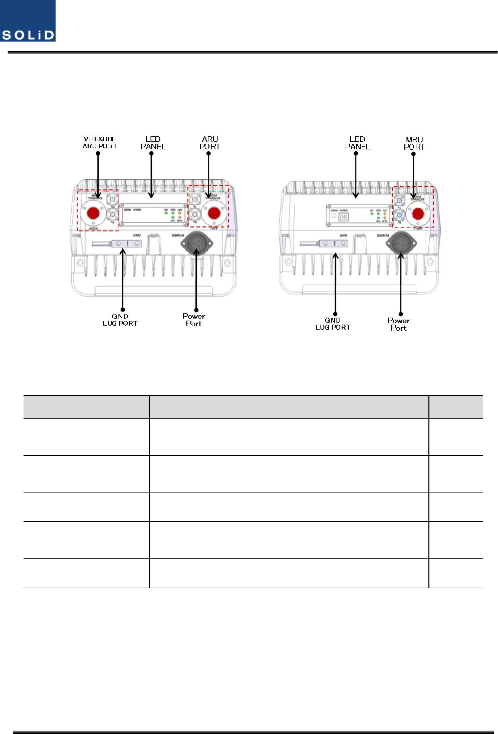
4.4.4 BottomofROU
1)Functions
(a)MRU(b)ARU
Figure4.38–ROUBottomview
ItemDescriptionRemark
1.VHF/UHFARUPortTerminalforTXandRXRFportsofVHFandUHF
TerminalforsignalporttointerfacewithVHFandUHF
2.LEDPANELVisibleLEDindicatorpanelforcheckingfaultstatusUSBPortto
checkandcontroldevicestatusthroughPCandlaptop
3.PowerPortAC120VinputportorDC‐48Vinputport
4.ARU/MRUPortTerminalforTXandRXRFportsofMRU/ARU
TerminalforsignalporttointerfacewithMRU/ARU
5.GNDLUGPORTTerminalforsystemground
PowerPort
Adifferenttypeofpowerportisusedsupplying‐48VDCor120VAC,andspecificpower
cableshouldbeappliedtoeachdifferenttypeofROUpowersupply(AC/DCorDC/DC).
Belowfigureshowsdifferentpowerconnectors.

Confidential&Proprietary56/115 SC‐DAS
(a)AC/DC(b)DC/DC
Figure4.39–ROUPowerPortView
Confidential&Proprietary57/115 SC‐DAS
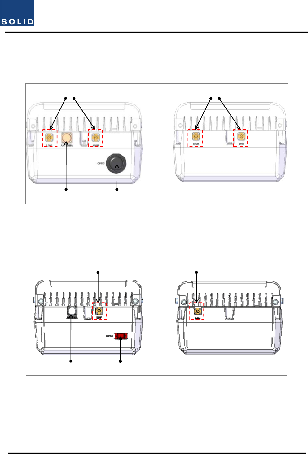
4.4.5 TopofROU
4.4.5.1 CombinationofMRU1900PCS+850C/ARU700LTE+AWS‐1
RFPORT
OpticPort
ANT
Port
RFPORT
(a)MRU(b)ARU
Figure4.40–ROUTopViewforMRU1900P+850CandARU700LTE+AWS‐1
4.4.5.2 CombinationofMRU1900PCS+850C/ARU700LTE+AWS‐1
RFPORT
OpticPort
ANT
Port
RFPORT
(a)MRU(b)ARU
Figure4.41–ROUTopViewforMRU1900P+850CandARU700LTE+AWS‐1