SOLiD H700PS RDU Module (700PS) User Manual Manual
SOLiD, Inc. RDU Module (700PS) Manual
UserManual.wiki
>
SOLiD
>
H700PS User Manual
User Manual
Navigation menu
Upload a User Manual
Namespaces
Wiki Guide
HTML
PDF
Info
Views
User Manual
Discussion / Help
Navigation
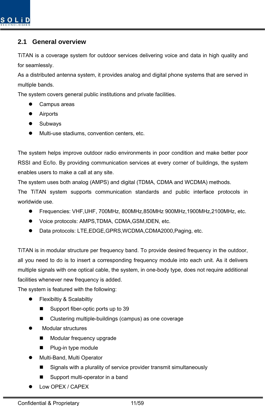
![Confidential & Proprietary 12/59 Compact design Upgradable design Easy installation and maintenance 2.2 System overview TiTAN is composed of devices given below. HMRU(High power Main Unit) HARU(High power Add-on Main Unit) A HMRU can support up to three ARU. HMRU transmits/receives optical signal from/to ODU and OEU. The budget of optical link is maximum 10dBo with DOU supported 1optical port and can support up to 5dBo with existing DOU supported 4optical port. System topology is like below. MRU ARU1 ARU2 ARU3Fr om ODU/OEUCU1 CU 21900PCS/850C/700LTE/AWS-100700PS/800PS/900ISeparate antenna per band Figure 2.1 – Basic system topology Table 3.1 – System topology Charts System elements Optical Loss [dBo] Remark With DOU supported 1optical port 1~10dBo With DOU supported 4optical port 1~5dBo](https://usermanual.wiki/SOLiD/H700PS/User-Guide-1695511-Page-12.png)
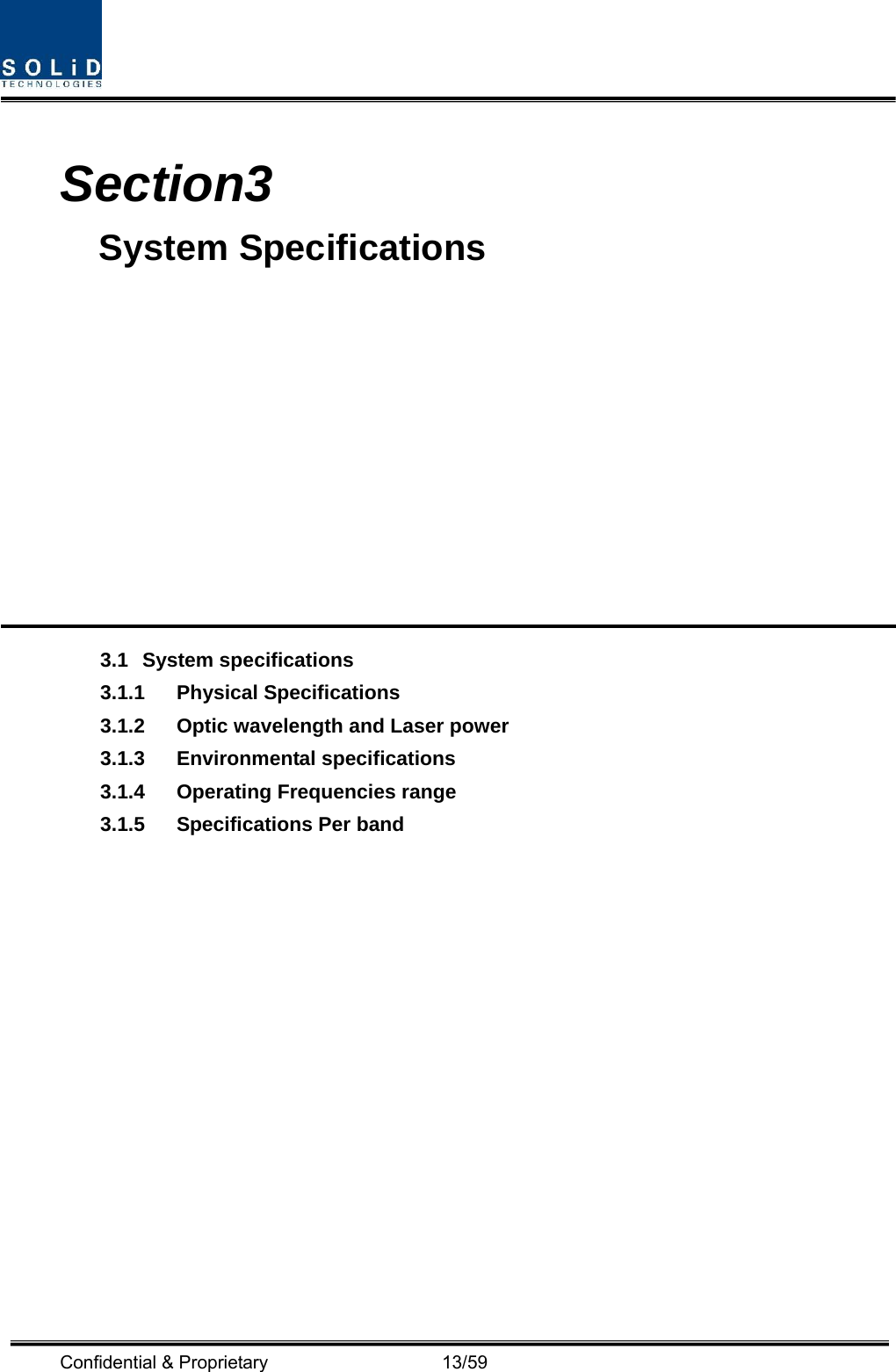
![Confidential & Proprietary 14/59 3.1 System specifications 3.1.1 Physical Specifications Parameter HMRU HARU RF Connectors 3N-type,female 6SMBL, female 1N-type,female 2SMBL, female Serial Interface connector 1 RS-232 9-pin D-sub, male 1 RS-232 9-pin D-sub, male Fiber connector 1 SC/APC - LED Alarm and Status Indicator System status z Power on status z TX Communication z RX Communication z LD status z PD status z ALM status System status z Power on status z TX Communication z RX Communication z LD status z PD status z ALM status AC Power Normal Range: 120VAC 50/60Hz Operating range 108~132VAC,50/60Hz Normal Range: 120VAC 50/60Hz Operating range 108~132VAC,50/60Hz Power consumption 50W Common part only 40W Common part only Enclosure Dimensions 360 x 700 x 280mm 360 x 700 x 280mm Weight[Common part] 28Kg 27Kg 3.1.2 Optic wavelength and Laser power Parameter HROU Remark Wavelength TX: 1550nm RX: 1310nm Output power 7dBm±1dBm to ODU 3.1.3 Environmental specifications Parameter HMRU,HARU Remark Operating Temperature -30 to +55°C Operating Humidity 5% to 90%,Non-condensing](https://usermanual.wiki/SOLiD/H700PS/User-Guide-1695511-Page-14.png)