User Manual
Confidential & Proprietary 1/59
TiTAN
Installation and Operation Manual
Document Reference:
Version: V1.0
Document Status: Release 1
Issue Date: MAR. 03, 2012
Author: Kyung Eun Han
Department: R&D Division Team 3
Authorizing Manager: Youngshin Yeo

Confidential & Proprietary 2/59
REVISION HISTORY
Version Issue Date No. of
Pages Initials Details of Revision Changes
V 1.0 MAR. 03, 2012 Original
Technical Support
SOLiD serial numbers must be available to authorize technical support and/or to establish a
return authorization for defective units. The serial numbers are located on the back of the unit,
as well as on the box in which they were delivered. Additional support information may be
obtained by accessing the SOLiD Tehcnology, Inc. website at www.st.co.kr or send email at
sjkim@st.co.kr
This manual is produced by Global Business Division Business Team 1. Printed in Korea.

Confidential & Proprietary 3/59
Contents
Section1 Safety & Certification Notice................................................................... 8
Section2 System Overview ...................................................................................10
2.1 General overview ......................................................................................... 11
2.2 System overview.......................................................................................... 12
Section3 System Specifications...........................................................................13
3.1 System specifications ................................................................................. 14
3.1.1 Physical Specifications......................................................................... 14
3.1.2 Optic wavelength and Laser power...................................................... 14
3.1.3 Environmental specifications............................................................... 14
3.1.4 Operating Frequencies range............................................................... 15
3.1.5 Specifications Per band ........................................................................ 16
3.1.5.1 700MHz LTE............................................................................................ 16
3.1.5.2 700MHz Public safety ............................................................................ 16
3.1.5.3 800MHz Public safety ............................................................................ 17
3.1.5.4 850MHz Cellular ..................................................................................... 17
3.1.5.5 900MHz iDEN & Paging ......................................................................... 18
3.1.5.6 1900MHz PCS......................................................................................... 18
3.1.5.7 1700MHz&2100MHz AWS-1 ................................................................... 19
Section4 System Configuration and Functions.................................................. 20
4.1 HROU (High power Remote Optic Unit) ..................................................... 21
4.1.1 Specifications of HROU......................................................................... 22
4.1.2 Block Diagram of HROU........................................................................ 22
4.1.2.1 HMRU block diagram............................................................................. 22
4.1.2.2 HARU block diagram ............................................................................. 23
4.1.3 HROU parts............................................................................................. 24
4.1.3.1 HROU inner look .................................................................................... 24
4.1.3.2 HROU part list ........................................................................................ 25
4.1.4 Function by unit..................................................................................... 26
4.1.5 Bottom of HROU .................................................................................... 30
Section5 System Installation................................................................................ 32
5.1 HROU Installation......................................................................................... 33
5.1.1 Tools........................................................................................................ 33

Confidential & Proprietary 4/59
5.1.2 HROU Enclosure installation................................................................ 34
5.1.3 How to expand ARU at the HMRU ........................................................ 38
5.1.4 HROU Power Cabling ............................................................................ 40
5.1.5 HROU Ground cabling........................................................................... 41
5.1.6 Optical Cabling ...................................................................................... 43
5.1.7 Mounting of RDU.................................................................................... 45
5.1.8 How to mount FAN Unit......................................................................... 50
5.1.9 Consumption of HROU.......................................................................... 51
Section6 Operation................................................................................................52
6.1 HROU Operation .......................................................................................... 53
6.1.1 HROU Operation .................................................................................... 53

Confidential & Proprietary 5/59
Contents of Figure
Figure 2.1 – Basic system topology ............................................................... 12
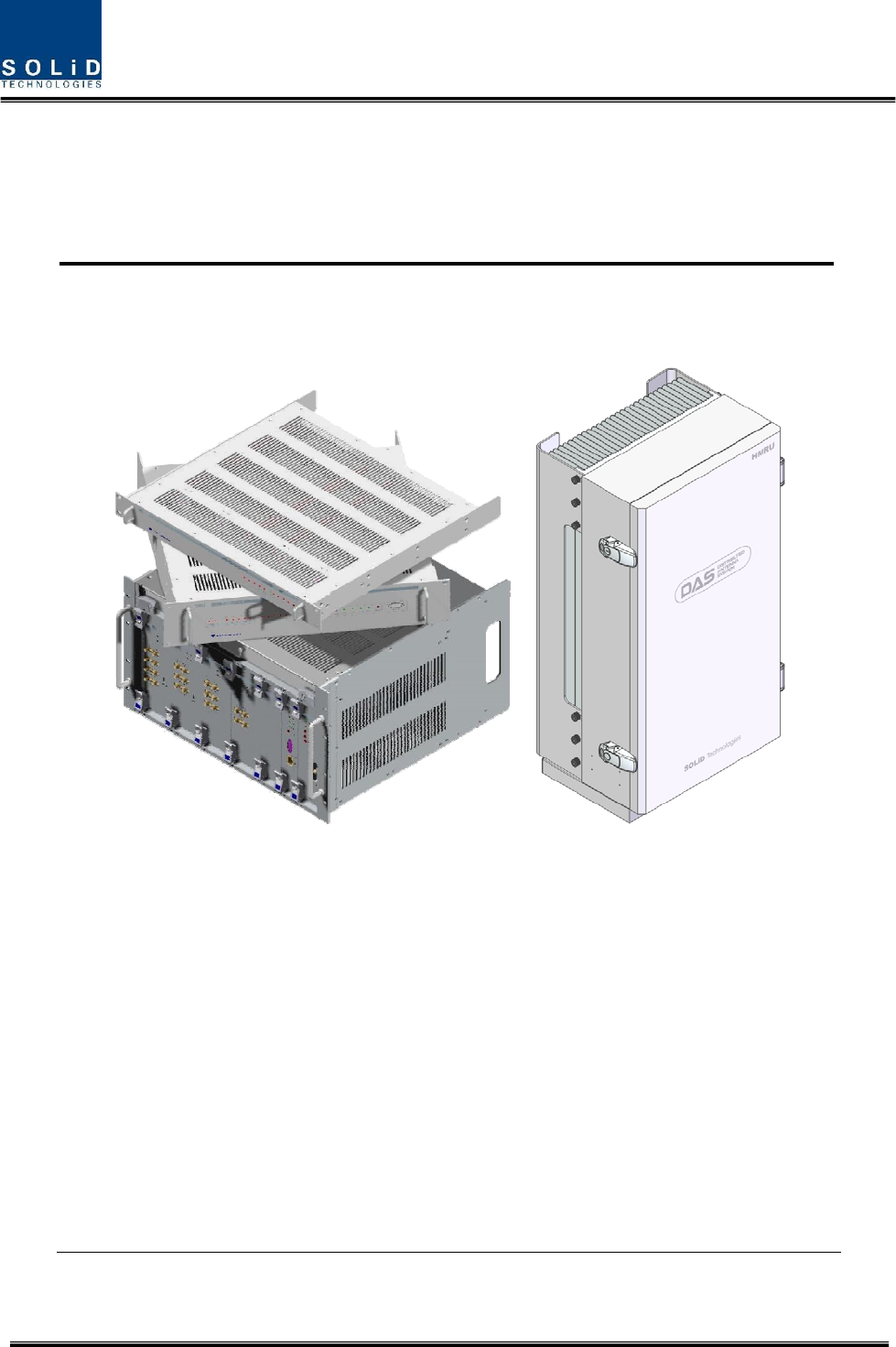
Figure 4.1 – HROU Outer Look ................................................................... 21
Figure 4.2 – HMRU Block diagram............................................................. 22
Figure 4.3 – HARU Block diagram ............................................................. 23
Figure 4.4 – HROU Inner Look .................................................................... 24
Figure 4.5 – RDU Outer Look ...................................................................... 26
Figure 4.6 – RPSU Outer Look .................................................................... 28
Figure 4.7 – R OPTIC Outer Look ............................................................... 29
Figure 4.8 – RCPU Outer Look.................................................................... 29
Figure 4.9 – SIU Outer Look........................................................................ 30
Figure 4.10 – HROU Bottom Look ............................................................... 30
Figure 5.1 – How to install HROU ............................................................. 34
Figure 5.2 – Dimension used to install HROU on the WALL .......................... 35
Figure 5.3 – Procedures of installation....................................................... 36
Figure 5.4 – Connection diagram between HMRU and HARU ................ 39
Figure 5.5 – Location of Ground Terminal ................................................. 41
Figure 5.6 – Information of Terminal........................................................... 41
Figure 5.7 – How to install Ground Terminal............................................. 42
Figure 5.8 – How to work optical port ....................................................... 43
Figure 5.9 – Wrong optical port installation method.................................. 44
Figure 5.10 – How to mount RDU ............................................................. 45
Figure 5.11 – The Guide bar ...................................................................... 46
Figure 5.12 – RDU accessories .................................................................. 46

Confidential & Proprietary 6/59
Figure 5.12 – RDU and accessories .......................................................... 47
Figure 5.13 – Installation diagram of RDU ................................................ 47
Figure 5.14 – Connection diagram of RDU1 ............................................. 48
Figure 5.14 – Connection diagram of RDU2 ............................................. 49
Figure 5.14 – How to mount FAN Unit ...................................................... 50
Figure 6.1 – Level diagram ......................................................................... 53
Figure 6.2 – ID setting Menu ...................................................................... 55
Figure 6.3 – Communication LED indicator................................................ 55
Figure 6.4 – Optic information window ....................................................... 56
Figure 6.5 – Information HROU and RDU ID............................................ 57
Figure 6.6 – RDU Setting window .............................................................. 57
Figure 6.7 – Fan information....................................................................... 59
Figure 6.8 – Fan setting window ................................................................ 59

Confidential & Proprietary 7/59
Glossary
HROU : High Power Remote Optical Unit, is composed of HMRU and HARU
HMRU : High Power Main Remote Unit
HARU : High Power Add-on Remote Unit

Confidential & Proprietary 8/59
Section1
Safety & Certification Notice

Confidential & Proprietary 9/59
“Only qualified personnel are allowed to handle this unit. Read and obey all the
warning labels attached in this user manual”
Any personnel involved in installation, operation or service of the SOLiD Technology
repeaters must understand and obey the following:
- Obey all general and regional installation and safety regulations relating to work on high
voltage installations, as well as regulations covering correct use of tools and personal protective
equipment.
- The power supply unit in repeaters contains dangerous voltage level, which can cause electric
shock. Switch the mains off prior to any work in such a repeater. Any local regulations are to be
followed when servicing repeaters.
- The repeater cover should be (door) securely fastened in open position, e.g. by tying it up, at
outdoor work in order to prevent door from slamming due to wind causing bodily harm or
damage.
- Use this unit only for the purpose specified by the manufacturer. Do not carry out any
modifications or fit any spare parts which are not sold or recommended by the manufacturer.
This could cause fires, electric shock or other injuries.
- Any repeater, including this repeater, will generate radio signals and thereby give rise to
electromagnetic fields that may be hazardous to the health of any person who is extensively
exposed to the signals at the immediate proximity of the repeater and the repeater antennas.
- Due to power dissipation, repeater may reach a very high temperature. Do not operate this
unit on or close to flammable materials.
- Do not use any solvents, chemicals, or cleaning solutions containing alcohol, ammonia, or
abrasives.
- Certification
z FCC: This equipment complies with the applicable sections of Title 47 CFR Parts 15,22,24
27 and 90
z UL/CUL: This equipment complies with UL and CUL 1950-1 Standard for safety for
information technology equipment,including electrical business equipment
z FDA/CDRH: This equipment uses a Class 1 LASER according to FDA/CDRH Rules.This
product conforms to all applicable standards of 21 CFR Chapter 1, Subchaper J, Part 1040
-For PLUGGABLE EQUIPMENT, the socket-outlet shall be installed near the equipment and
shall be easily accessible.

Confidential & Proprietary 10/59
Section2
System Overview
2.1 General overview
2.2 System overview

Confidential & Proprietary 11/59
2.1 General overview
TiTAN is a coverage system for outdoor services delivering voice and data in high quality and
for seamlessly.
As a distributed antenna system, it provides analog and digital phone systems that are served in
multiple bands.
The system covers general public institutions and private facilities.
z Campus areas
z Airports
z Subways
z Multi-use stadiums, convention centers, etc.
The system helps improve outdoor radio environments in poor condition and make better poor
RSSI and Ec/Io. By providing communication services at every corner of buildings, the system
enables users to make a call at any site.
The system uses both analog (AMPS) and digital (TDMA, CDMA and WCDMA) methods.
The TiTAN system supports communication standards and public interface protocols in
worldwide use.
z Frequencies: VHF,UHF, 700MHz, 800MHz,850MHz 900MHz,1900MHz,2100MHz, etc.
z Voice protocols: AMPS,TDMA, CDMA,GSM,IDEN, etc.
z Data protocols: LTE,EDGE,GPRS,WCDMA,CDMA2000,Paging, etc.
TiTAN is in modular structure per frequency band. To provide desired frequency in the outdoor,
all you need to do is to insert a corresponding frequency module into each unit. As it delivers
multiple signals with one optical cable, the system, in one-body type, does not require additional
facilities whenever new frequency is added.
The system is featured with the following:
z Flexibiltiy & Scalabiltiy
Support fiber-optic ports up to 39
Clustering multiple-buildings (campus) as one coverage
z Modular structures
Modular frequency upgrade
Plug-in type module
z Multi-Band, Multi Operator
Signals with a plurality of service provider transmit simultaneously
Support multi-operator in a band
z Low OPEX / CAPEX
Confidential & Proprietary 12/59
Compact design
Upgradable design
Easy installation and maintenance
2.2 System overview
TiTAN is composed of devices given below.
HMRU(High power Main Unit)
HARU(High power Add-on Main Unit)
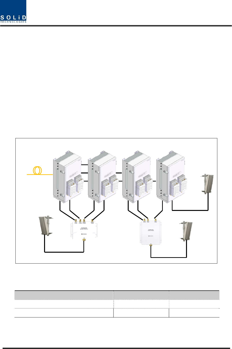
A HMRU can support up to three ARU. HMRU transmits/receives optical signal from/to ODU
and OEU. The budget of optical link is maximum 10dBo with DOU supported 1optical port and
can support up to 5dBo with existing DOU supported 4optical port. System topology is like
below.
MRU ARU1 ARU2 ARU3
Fr om ODU/OEU
CU1 CU 2
1900PCS/850C/700LTE/AWS-100
700PS/800PS/900I
Separate antenna per band
Figure 2.1 – Basic system topology
Table 3.1 – System topology Charts
System elements Optical Loss [dBo] Remark
With DOU supported 1optical port 1~10dBo
With DOU supported 4optical port 1~5dBo

Confidential & Proprietary 13/59
Section3
System Specifications
3.1 System specifications
3.1.1 Physical Specifications
3.1.2 Optic wavelength and Laser power
3.1.3 Environmental specifications
3.1.4 Operating Frequencies range
3.1.5 Specifications Per band

Confidential & Proprietary 14/59
3.1 System specifications
3.1.1 Physical Specifications
Parameter HMRU HARU
RF Connectors 3N-type,female
6SMBL, female
1N-type,female
2SMBL, female
Serial Interface connector 1 RS-232 9-pin
D-sub, male
1 RS-232 9-pin
D-sub, male
Fiber connector 1 SC/APC -
LED Alarm and
Status Indicator
System status
z Power on status
z TX Communication
z RX Communication
z LD status
z PD status
z ALM status
System status
z Power on status
z TX Communication
z RX Communication
z LD status
z PD status
z ALM status
AC Power
Normal Range: 120VAC 50/60Hz
Operating range
108~132VAC,50/60Hz
Normal Range: 120VAC 50/60Hz
Operating range
108~132VAC,50/60Hz
Power consumption 50W
Common part only
40W
Common part only
Enclosure Dimensions 360 x 700 x 280mm 360 x 700 x 280mm
Weight[Common part] 28Kg 27Kg
3.1.2 Optic wavelength and Laser power
Parameter HROU Remark
Wavelength
TX: 1550nm
RX: 1310nm
Output power 7dBm±1dBm to ODU
3.1.3 Environmental specifications
Parameter HMRU,HARU Remark
Operating Temperature -30 to +55°C
Operating Humidity 5% to 90%,Non-condensing

Confidential & Proprietary 15/59
3.1.4 Operating Frequencies range
Frequency range
Standard Unit naming Description TX(MHz) RX(MHz)
LTE 700LTE LTE 728 to 756
698 to 716
777 to 787
iDEN 700PS Public safety 758 to 775 788 to 805
iDEN 800I/PS Public safety 851 to 869 806 to 824
Cellular 85C0C Cellular 869 to 894 824 to 849
Iden 900IDED SMR 929 to 940 896 to 902
Paging 900 PA Paging 929 to 930 896 to 902
PCS 1900PCS PCS 1930 to 1995 1850 to 1915
AWS-1 AWS-1 AWS-1 2110 to 2155 1710 to 1755
Confidential & Proprietary 16/59
3.1.5 Specifications Per band
3.1.5.1 700MHz LTE
Typical Remarks
Parameters TX RX
Bandwidth 28MHz 18MHz/10MHz
System ripple ≤4dB ≤4dB
Input Power level -20 to +10dBm ≤-50dBm
Output power +44.5dBm +0dBm Total
System Gain 64.5dB 50dB
Gain Control range 39.5 to 64.5dB 30 to 50dB
Spurious Emissions -13dBm -
IP3 - +23dBm
Noise figure - 8dB 1HROU
3.1.5.2 700MHz Public safety
Typical Remarks
Parameters TX RX
Bandwidth 17MHz 17MHz
System ripple ≤4dB ≤4dB
Input Power level -20 to +10dBm ≤-50dBm
Output power +44.5dBm +0dBm Total
System Gain 64.5dB 50dB
Gain Control range 39.5 to 64.5dB 30 to 50dB
Spurious Emissions -13dBm -
IP3 - +23dBm
Noise figure - 8dB 1HROU

Confidential & Proprietary 17/59
3.1.5.3 800MHz Public safety
Typical Remarks
Parameters TX RX
Bandwidth 18MHz 18MHz
System ripple ≤4dB ≤4dB
Input Power level -20 to +10dBm ≤-50dBm
Output power +44.5dBm +0dBm Total
System Gain 64.5dB 50dB
Gain Control range 39.5 to 64.5dB 30 to 50dB
Spurious Emissions -13dBm -
IP3 - +23dBm
Noise figure - 8dB 1HROU
3.1.5.4 850MHz Cellular
Typical Remarks
Parameters TX RX
Bandwidth 25MHz 25MHz
System ripple ≤4dB ≤4dB
Input Power level -20 to +10dBm ≤-50dBm
Output power +44.5dBm +0dBm Total
System Gain 64.5dB 50dB
Gain Control range 39.5 to 64.5dB 30 to 50dB
Spurious Emissions -13dBm -
IP3 - +23dBm
Noise figure - 8dB 1HROU
Confidential & Proprietary 18/59
3.1.5.5 900MHz iDEN & Paging
Typical Remarks
Parameters TX RX
Bandwidth 12MHz 6MHz
System ripple ≤4dB ≤4dB
Input Power level -20 to +10dBm ≤-50dBm
Output power +44.5dBm +0dBm Total
System Gain 64.5dB 50dB
Gain Control range 39.5 to 64.5dB 30 to 50dB
Spurious Emissions -13dBm -
IP3 - +23dBm
Noise figure - 8dB 1HROU
3.1.5.6 1900MHz PCS
Typical Remarks
Parameters TX RX
Bandwidth 65MHz 65MHz
System ripple ≤5dB ≤5dB
Input Power level -20 to +10dBm ≤-50dBm
Output power +44.5dBm +0dBm Total
System Gain 64.5dB 50dB
Gain Control range 39.5 to 64.5dB 30 to 50dB
Spurious Emissions -13dBm -
IP3 - +23dBm
Noise figure - 8dB 1HROU

Confidential & Proprietary 19/59
3.1.5.7 1700MHz&2100MHz AWS-1
Typical Remarks
Parameters TX RX
Bandwidth 45MHz 45MHz
System ripple ≤5dB ≤5dB
Input Power level -20 to +10dBm ≤-50dBm
Output power +44.5dBm +0dBm Total
System Gain 64.5dB 50dB
Gain Control range 39.5 to 64.5dB 30 to 50dB
Spurious Emissions -13dBm -
IP3 - +23dBm
Noise figure - 8dB 1HROU

Confidential & Proprietary 20/59
Section4
System Configuration and Functions
4.1 HROU (High power Remote Optic Unit)
Confidential & Proprietary 21/59
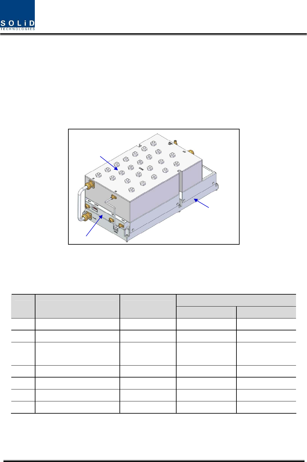
4.1 HROU (High power Remote Optic Unit)
HROU consists of two unit, one is HMRU(High power Main Remote Unit) and the other is
HARU(High power Add-on Remote Unit).
The biggest difference between HMRU and HARU is whether R-OPTIC module exist or not.
HMRU receives TX optical signals from ODU or OEU and converts them into RF signals. The
converted RF signals are amplified through High Power Amp in a corresponding RDU combined
with RFU, PAU and Cavity duplexer, and then radiated to the antenna port.
When receiving RX signals through the antenna port, this unit filters out-of-band signals in a
corresponding RDU and sends the results to R-OPTIC to make electronic-optical conversion of
them. After converted, the signals are sent to a upper device of ODU or OEU. HMRU can be
equipped with up to two RDUs (Remote Drive Unit) and the module supports single band only.
HARU receives TX RF signal from HMRU and amplifies through High Power Amp in a
corresponding RDU combined with RFU, PAU and Cavity duplexer, and then radiated to the
antenna port
When receiving RX signals through the antenna port, RDU filters out-of band signal in a
corresponding RDU and sends the results to MHRU through RF cable.
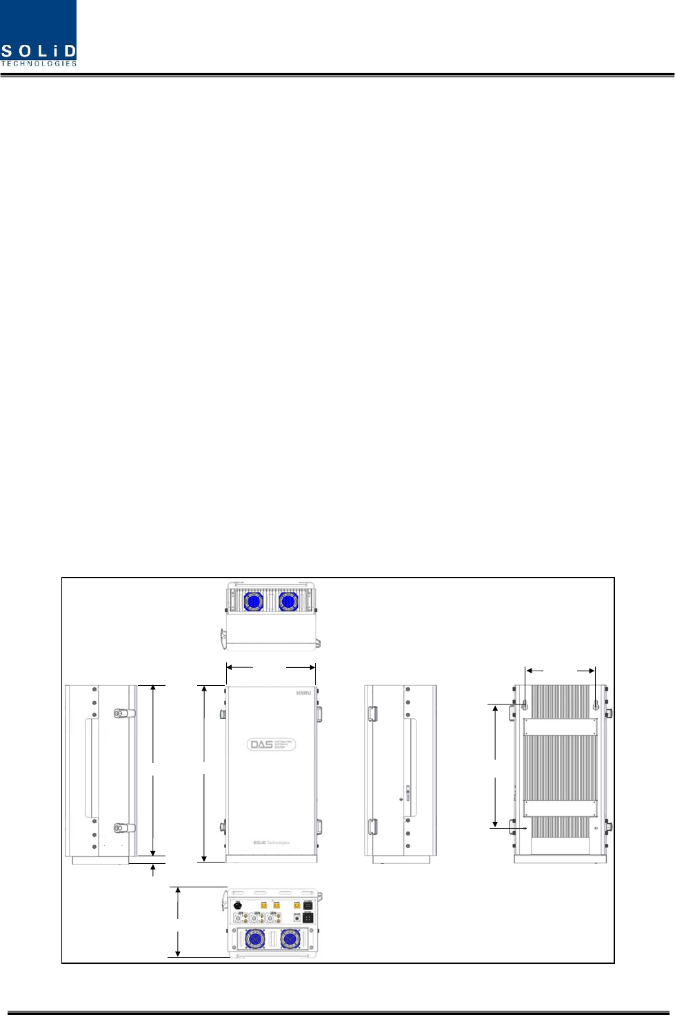
360mm
700mm
670mm
30mm
280mm
280mm
500mm
Figure 4.1 – HROU Outer Look
Confidential & Proprietary 22/59
4.1.1 Specifications of HROU
Spec.
Item HMRU HARU Remark
Size(mm) 360 x 700 x280 Including Bracket
Weight 28 Kg 27kg
Power consumption 50W 40W
Common Part
4.1.2 Block Diagram of HROU
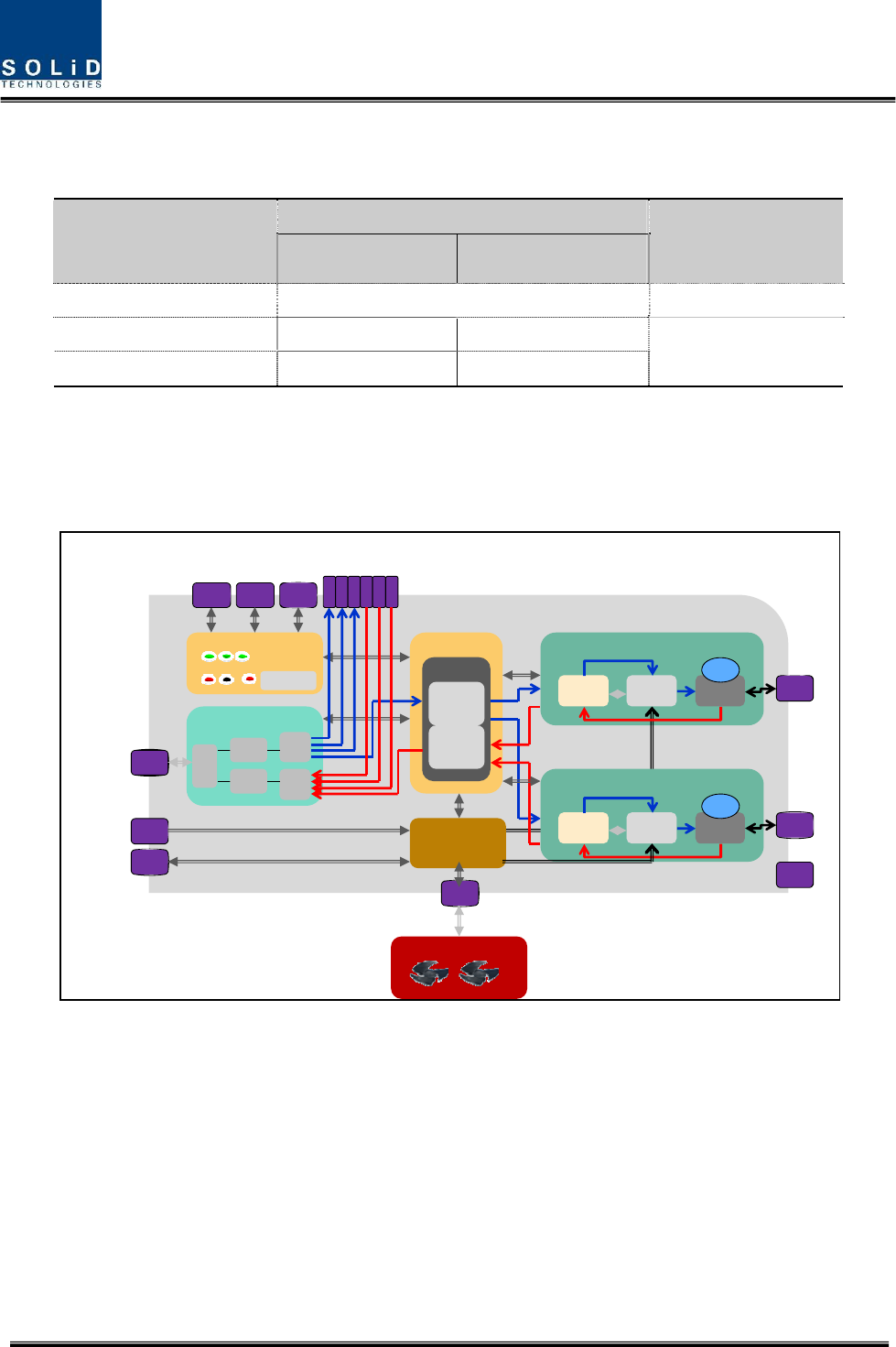
4.1.2.1 HMRU block diagram
SIU
2WAY
XXX RDU
RCPU
RXD
Reset
ON TXD
ALM Opt
Debug
RPSU
TX
RX
ROPTIC
W
D
M
4
W
4
W
RFU PA U DUP
FA N U N I T
AC POWER
MS-
CON
MS-
CON
Bat t er y
OPTIC
I/O1
I/O2
I/O3
MS-
CON
MS-
CON
MS-
CON
SM BL
SM BL
SM BL
SM BL
SM BL
SM BL
TX1
TX2
TX3
RX1
RX2
RX3
MS-
CON
N(F)
XXX RDU
RFU PA U DUP N(F)
N(F)
1
ST
ANT
2
ND
ANT
3
RD
ANT
FAN EXT
LD
FSK
PD
FSK
M
40
M
40
Figure 4.2 – HMRU Block diagram
Confidential & Proprietary 23/59
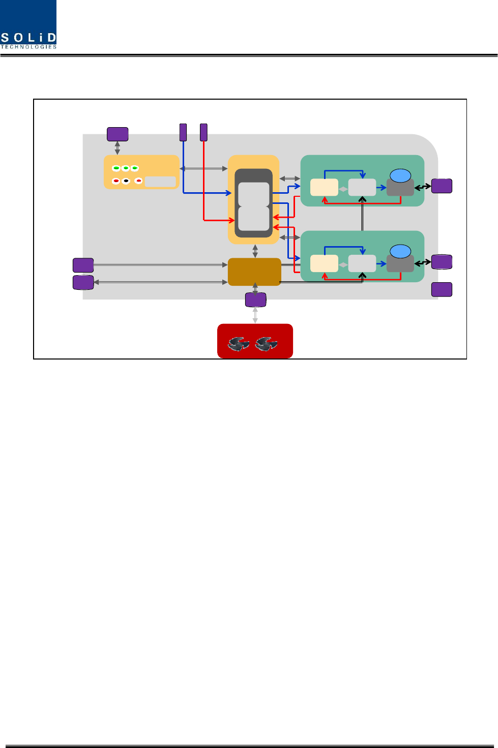
4.1.2.2 HARU block diagram
SIU
2WAY
TX
RX
XXX RDU
RCPU
RXD
Reset
ON TXD
ALM Opt
Debug
RPSU
RFU PA U DUP
FA N U N I T
AC POWER
MS-
CON
MS-
CON
Bat t er y
I/O1
MS-
CON
SM BL
SM BL
TX1
RX1
MS-
CON
N(F)
XXX RDU
RFU PA U DUP N(F)
N(F)
1
ST
ANT
2
ND
ANT
3
RD
ANT
FAN EXT
M
40
M
40
Figure 4.3 – HARU Block diagram
Confidential & Proprietary 24/59
4.1.3 HROU parts
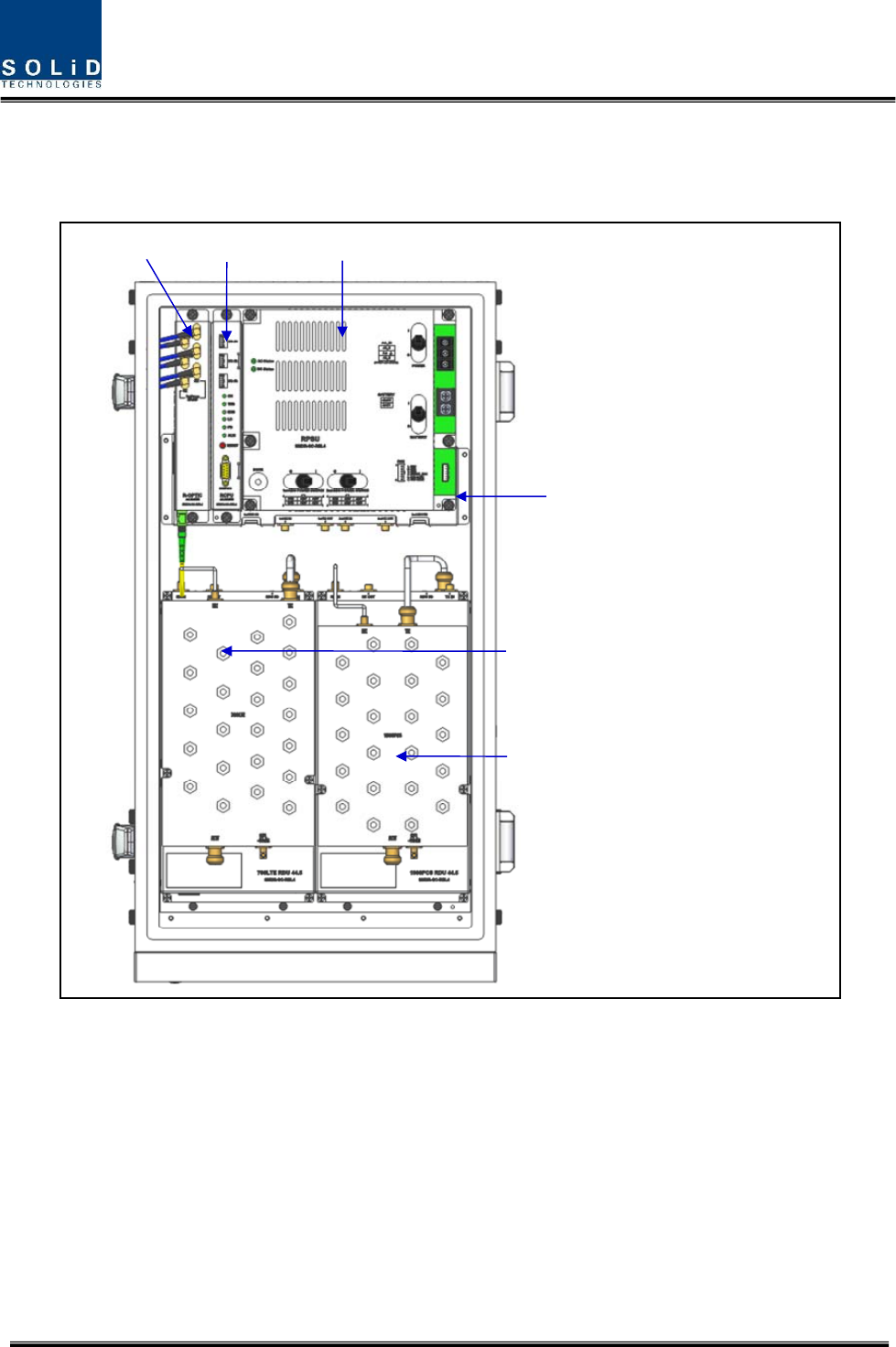
4.1.3.1 HROU inner look
1
st
BAND slot: XXX RDU44.5
R-OPTIC RCPU RPSU
2
nd
BAND slot: XXX RDU44.5
SI U A ss’y
Figure 4.4 – HROU Inner Look

Confidential & Proprietary 25/59
4.1.3.2 HROU part list
No. Unit Description Remark
1 R-OPTIC
Remote Optic
Make RF conversion of TX optical signals;
Convert RX RF signals into optical signals;
Compensates optical loss
Communicates with BIU/OEU though the FSK modem
Optional
Only HMRU
2 RCPU
Remote Central Processor Unit
Monitoring status of each unit
Communicating with BIU/ODU/OEU
Support LED indicators on it to check alarm
Common
3 RPSU Remote Power Supply Unit
Input power: 120V, Output power: 28V single voltage Common
4 SIU Ass’y Distributes data signal and power signal to each
module Common
5 RDU
Remote Drive Unit
Consist of RFU, PAU and cavity filter
Filter and high amplify TX signals;
Filter and amplify RX signals in low noise amplifier;
Remove out-of signals through cavity duplexer
Optional
Max 2
6 Enclosure Enclosure to satisfy NEMA4;
Enable Wall/Rack Mount Common
7 FAN Unit
FAN Unit
Attach outside of enclosure
Cool the enclosure’s heat using two fans
Operate either on or off according to designated
temperature
Common
Confidential & Proprietary 26/59
4.1.4 Function by unit
1) Remote Drive Unit (RDU)
When receiving TX signals from each band through Remote Optic, RDU filters the signals and
amplifies them with High Power Ampifier. The unit also filters RX signals given through cavity
filter and amplifies them to send the signals to Remote Optic.In the unit, there is ATT to adjust
gain. RDU consist of RFU, PAU and cavity duplexer like below figure and all modules are
merged with one package
PAU
RFU
D U PLEX ER
Figure 4.5 – RDU Outer Look
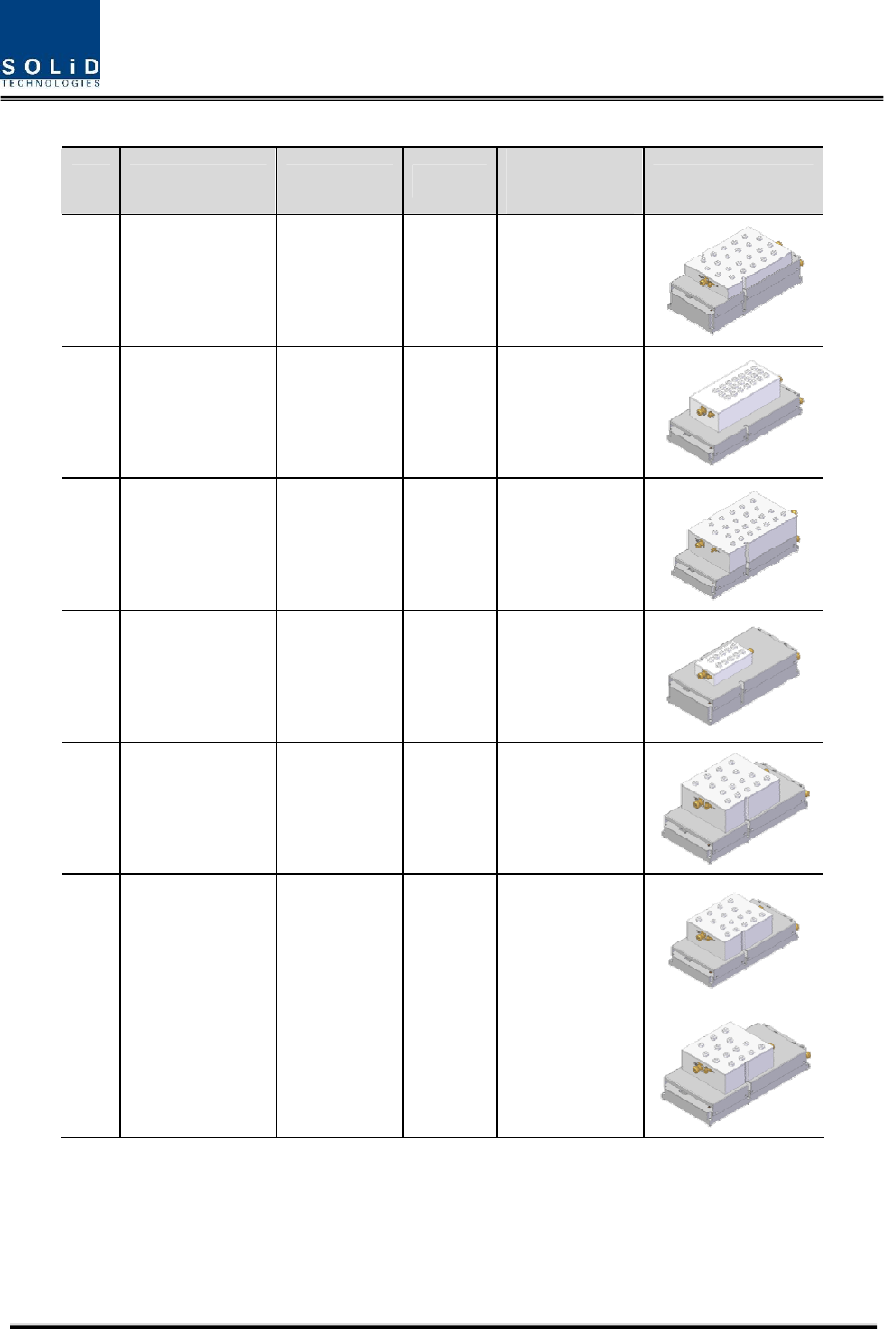
RDU devices are varied for each frequency band, including the following:
Frequency
No Unit naming Description TX RX
1 1900PCS RDU44.5 Single band 1930-1995MHz 1850-1915MHz
2 850CEL RDU44.5 Single band 869-894MHz 824-849MHz
3 700LTE RDU44.5 Single band 728-756MHz
698-716MHz
777-787MHz
4 AWS-1 RDU44.5 Single band 2110-2155MHz 1710-1755MHz
5 700PS RDU44.5 Single band 758-775MHz 788-805MHz
6 800I/PS RDU44.5 Single band 851-869MHz 806-824MHz
7 900I RDU44.5 Single band 929-941MHz 896-902MHz
Confidential & Proprietary 27/59
No Unit naming Dimension Weight Power
consumption Outlook
1 1900PCS RDU44.5 150x310x112 7kg 350W
2 850CEL RDU44.5 150x310x116 7kg 300W
3 700LTE RDU44.5 150x310x120 7kg 300W
4 AWS-1 RDU44.5 150x310x113 6kg 330W
5 700PS RDU44.5 150x310x132 6kg 320W
6 800I/PS RDU44.5 150x310x128 6.5kg 300W
7 900I RDU44.5 150x310x123 6.5kg 300W
Confidential & Proprietary 28/59
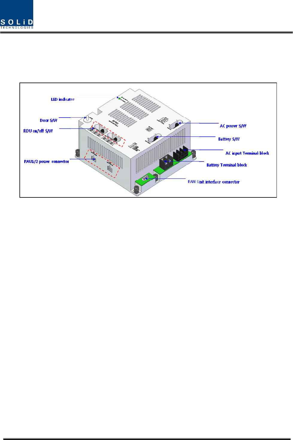
2) Remote Power Supply Unit (RPSU)
RPSU is provided of 120Vac at input and provide output +28V only singl voltage of DC power
basically. Optionally, RSPU supports battery backup using battery port. Battery operates charge
and discharge function.
Figure 4.6 – RPSU Outer Look
Functions:
Providing a circuit breaker to turn the power ON/OFF
Providing a circuit breaker to turn battery ON/OFF
Providing DC power each RDU using RDU on/off switch
Providing DC power and signal to FAN tray
LED indicators for showing alarm staus of PSU
Door open/close status using Door switch
Confidential & Proprietary 29/59
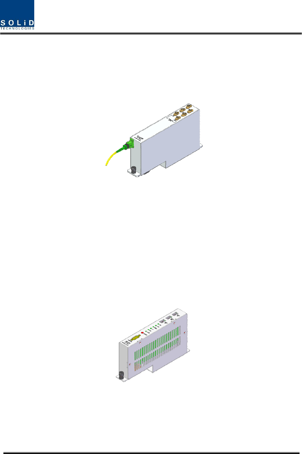
3) Remote Optic(R OPTIC)
Remote Optic converts optical signals into RF signals and performs vice versa. With an FSK
modem in it, the unit communicates with upper devices.
It also has internal ATT for optical compensation to compensate for optical cable loss. It
provides three path in pair to transport RF signal to ARUs
Figure 4.7 – R OPTIC Outer Look
4) Remote Central Processor Unit (RCPU)
RCPU can monitor and control each module of HROU. This unit receives and analyzes upper
communication data from Remote Optic and reports the unit's own value to upper devices. At
the front of the module, it has LED indicator to show system status, letting you check any
abnormalities at a time. At the same front, it also has communication LED Indicators to show
communication status with upper devices. Through RS-232C Serial Port, the unit enables you to
check and control device status through PC and laptop.
It provides three interface port with ARUs to communicate with these. RCPU is common module
for both HMRU and HARU.
Figure 4.8 – RCPU Outer Look
Confidential & Proprietary 30/59
5) System Interface Unit(SIU)
SIU distributes power and signals to each module.
Figure 4.9 – SIU Outer Look
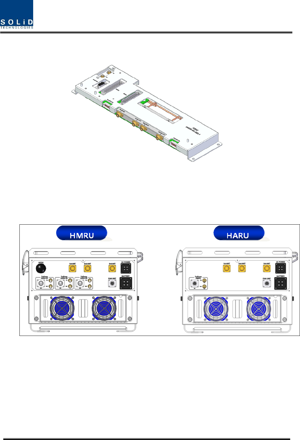
4.1.5 Bottom of HROU
1) Functions
Figure 4.10 – HROU Bottom Look

Confidential & Proprietary 31/59
No Port HMRU HARU Remark
1 Optical Port 1EA X SC/APC, Waterproof
2 ARU
Interface
3EA,
(3)CON,(6)SMBL-
Female
1EA,
(1)CON,(2)SMBL-
Female
3 1ST ANT 1EA 1EA N-type female, 1ST BAND
Antenna port
4 2ND ANT 1EA 1EA N-type female, 2ND
BAND Antenna port
5 3RD ANT 1EA 1EA N-type female, Reserved
port in future
6 AC Power 1EA 1EA MS-Con, Waterproof
7 Battery 1EA 1EA MS-Con, Waterproof
8 EXT-FAN 1EA 1EA Waterproof-Con