SOLiD HM700LM 5 Watt 700MHz Amplifier Module User Manual 9 User s manual REV6
SOLiD, Inc. 5 Watt 700MHz Amplifier Module 9 User s manual REV6
SOLiD >
Manual Rev2
Confidential & Proprietary 1/30
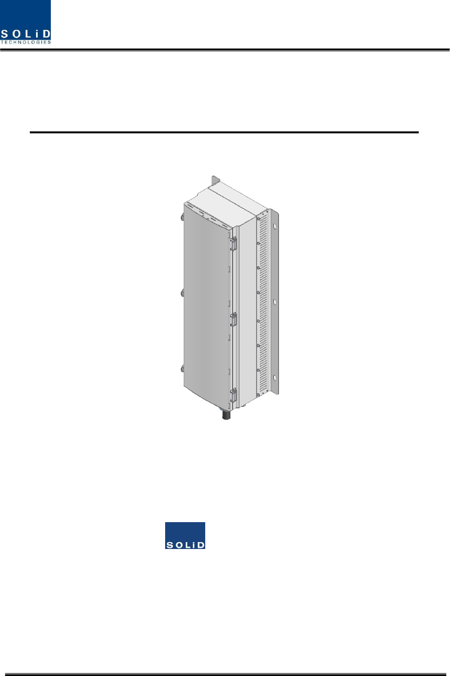
Hercules‐S(5WRemoteUnit)
UserManual
SOLiD,Inc.
10,9thFloor,SOLiDSpace220Pangyoyeok‐ro,Bundang‐gu,Seongnam‐si,Gyeonggi‐do,Korea393‐400
Tel:+82‐31‐627‐6290Fax:+82‐31‐627‐6209

Confidential & Proprietary 2/30
REVISIONHISTORY
VersionIssueDateNo.of
PagesInitialsDetailsofRevisionChanges
V1.0Oct.23,2013 Original
TechnicalSupport
SOLiDserialnumbersmustbeavailabletoauthorizetechnicalsupportand/ortoestablishareturn
authorizationfordefectiveunits.Theserialnumbersarelocatedonthebackoftheunit,aswellason
theboxinwhichtheyweredelivered.Additionalsupportinformationmaybeobtainedbyaccessingthe
SOLiDTehcnology,Inc.websiteatwww.solid.co.krorsendemailat
kehan@solid.co.kr
ThismanualisproducedbyGlobalBusinessDivisionBusinessTeam1.PrintedinKorea.

Confidential & Proprietary 3/30
Contents
Section1 Safety&CertificationNotice ......................................................................... 5
Section2 Introduction ................................................................................................ 8
2.1 Purpose ............................................................................................................. 9
2.2 HERCULES‐S ..................................................................................................... 10
Section3 FunctionalDescription ................................................................................ 11
3.1 General ........................................................................................................... 12
3.2 ComponentofHERCULES‐SRemoteUnit ........................................................... 13
3.3 Dimension ....................................................................................................... 15
Section4 SystemInstallation ..................................................................................... 16
4.1 REMOTEUNITInstallation ................................................................................ 18
4.1.1 REMOTEUNITEnclosureinstallation ................................................................. 18
4.1.2 RemoteUnitPowerCabling .............................................................................. 21
4.1.3 RemoteUnitOpticalCabling ............................................................................. 24
4.1.4 GNDTermina lConnection................................................................................. 25
4.1.5 CoaxialcableandAntennaConnection .............................................................. 26
Section5 SystemSpecifications ................................................................................. 27
5.1 PhysicalSpecifications ...................................................................................... 28
5.2 RFperformance ............................................................................................... 29
5.3 Certification ..................................................................................................... 30

Confidential & Proprietary 4/30
ContentsofFigure
Figure3.1–RemoteUnitBlockDiagram ............................................................. 12
Figure3.2–InsideofRemoteUnit ...................................................................... 13
Figure3.3–RemoteUnitDimension ................................................................... 15
Figure4.1–ExteriorofRemoteUnit ................................................................... 18
Figure4.2–DimensionusedtoinstallREMOTEUNITontheWALL ........................ 19
Figure4.3–HorizontalInstallation ..................................................................... 20
Figure4.4–InstallationClearance ...................................................................... 20
Figure4.5–HowtoInstallRemoteUnit .............................................................. 20

Confidential & Proprietary 5/30
Section1
Safety&CertificationNotice

Confidential & Proprietary 6/30
“OnlyqualifiedpersonnelshouldhandletheDASequipment.Anypersoninvolvedin
installationorserviceoftheDASshouldunderstandandfollowthesesafetyguidelines.”
‐Obeyallgeneralandregionalsafetyregulationsrelatingtoworkonhighvoltageinstallations,aswellas
regulationscoveringcorrectuseoftoolsandpersonalprotectiveequipment.
‐Topreventelectricalshock,switchthemainpowersupplyoffpriortoworkingwiththeDASSystemor
FiberBDA.Neverinstalloruseelectricalequipmentinawetlocationorduringalightningstorm.
‐Whenworkingwithunitsoutdoors,makesuretosecurelyfastenthedoororcoverinanopenposition
topreventthedoorfromslammingshutinwindyconditions.
‐Usethisunitonlyforthepurposespecifiedbythemanufacturer.Donotmodifyorfitanyspareparts
thatarenotsoldorrecommendedbythemanufacturer.Thiscouldcausefires,electricshockorother
injuries.
‐AnyDASsystemorFiberBDAwillgenerateradio(RF)signalsandcontinuouslyemitRFenergy.Avoid
prolongedexposuretotheantennas.SOLiDrecommendsmaintaininga2m(78.74inches)minimum
clearancefromtheantennawhilethesystemisoperating.
‐Donotoperatethisunitonorclosetoflammablematerials,astheunitmayreachhightemperatures
duetopowerdissipation.
‐Donotuseanysolvents,chemicals,orcleaningsolutionscontainingalcohol,ammonia,orabrasiveson
theDASequipment.Alcoholmaybeusedtocleanfiberopticcablingendsandconnectors.
‐Donotlookintotheendsofanyopticalfiberordirectlyintotheopticaltransceiverofanydigitalunit.
Useanopticalspectrumanalyzertoverifyactivefibers.Placeaprotectivecapoveranyradiating
transceiveroropticalfiberconnectortoavoidthepotentialofradiationexposure.
‐Allowsufficientfiberlengthtopermitroutingwithoutseverebends.
‐Forpluggableequipment,makesuretoinstallthesocketoutletneartheequipmentsothatitiseasily
accessible.
‐Certification
FCC:ThisequipmentcomplieswiththeapplicablesectionsofTitle47CFRParts15,22,24and90
UL/CUL:ThisequipmentcomplieswithULandCUL1950‐1Standardforsafetyforinformation
technologyequipment,includingelectricalbusinessequipment
FDA/CDRH:ThisequipmentusesaClass1LASERaccordingtoFDA/CDRHRules.Thisproduct
conformstoallapplicablestandardsof21CFRChapter1,SubchaperJ,Part1040
‐Areadyilyaccessibledisconnectdeviceshallbeincorporatedexternaltotheequipment.
‐Thispowerofthissystemshallbesuppliedthroughwiringinstalledinanormalbuilding.
Confidential & Proprietary 7/30
Ifpowereddirectlyfromthemainsdistributionsystem,itshallbeusedadditionalprotection,suchas
overvoltageprotectiondevice
‐Only50ohmratedantennas,cablesandpassiveequipmentshallbeusedwiththisremote.Any
equipmentattachedtothisdevicenotmeetingthisstandardmaycausedegradationandunwanted
signalsinthebi‐directionalsystem.Allcomponentsconnectedtothisdevicemustoperateinthe
frequencyrangeofthisdevice.
‐ Only50ohmratedantennas,cablesandpassivecomponentsoperatingfrom150‐3GHzshallbe
usedwiththisdevice.
‐Signalboosterwarninglabelmessageshouldinclude

Confidential & Proprietary 8/30
Section2
Introduction
2.1Purpose
2.2Hercules‐S

Confidential & Proprietary 9/30
2.1 Purpose
HERCULES‐Sisacoveragesystemforin‐buildingservicesdeliveringvoiceanddatainhighqualityandfor
seamlessly.
Asadistributedantennasystem,itprovidesanaloganddigitalphonesystemsthatareservedinmultiple
bandsthroughoneantenna.
Thesystemcoversgeneralpublicinstitutionsandprivatefacilities.
Shoppingmalls
Hotels
Campusareas
Airports
Clinics
Subways
Multi‐usestadiums,conventioncenters,etc.
Thesystemhelpsimprovein‐buildingradioenvironmentsinpoorconditionandmakebetterpoorRSSI
andEc/Io.Byprovidingcommunicationservicesateverycornerofbuildings,thesystemenablesusersto
makeacallatanysiteofbuildings.
Thesystemusesbothanalog(AMPS)anddigital(TDMA,CDMAandWCDMA)methods.
TheHERCULES‐Ssystemsupportscommunicationstandardsandpublicinterfaceprotocolsinworldwide
use.
Frequencies:700MHz,800MHz,850MHz,1900MHz,2100MHz,etc.
Voiceprotocols:AMPS,TDMA,CDMA,GSM,IDEN,etc.
Dataprotocols:EDGE,GPRS,WCDMA,CDMA2000,Paging,LTEetc.
HERCULES‐Sisinmodularstructureperfrequency.Toprovidedesiredfrequencyinabuilding,allyou
needtodoistoinsertacorrespondingfrequencymoduleintoeachunit.Asitdeliversmultiplesignals
withoneopticalcable,thesystem,inone‐bodytype,doesnotrequireadditionalfacilitieswhenever
newfrequencyisadded.
Thesystemisfeaturedwiththefollowing:
Flexibiltiy&Scalabiltiy
Supportfiber‐opticportsupto32
Clusteringmultiple‐buildings(campus)asonecoverage
Modularstructures
Modularfrequencyupgrade
Plug‐intypemodule
Multi‐Band,MultiOperator

Confidential & Proprietary 10/30
Signalswithapluralityofserviceprovidertransmitsimultaneously
Supportmulti‐operatorinaband
LowOPEX/CAPEX
Compactdesign
Upgradabledesign
Easyinstallationandmaintenance
2.2 HERCULES‐S
Hercules‐SisoneofseriesofAllianceDASandhas5W(+37dBm)compositeoutputpowereveryband.
RDUthatisintegratedonpackagewithDuplexer,PoweramplifierandRFunitcanbemountedupto5in
theenclosure.
Hercules‐Stransportssignalsthatmultipleoperatorsandmultipletechnologiesaremovedatasame
timefromBasestationtoaremotelocationoverthesamefiber.
Itisavailableinsingleandmulti‐bandconfigurationsupporting700MHz,800MHz,850MHz,
1700/2100MHz,1900MHzinparallel.
IthasbeenspecificllaytestedunteravariousairinterfacessuchasiDEN,GSM,CDMA2000,EV‐DO,
WCDMA,LTEete.
Furthermore,thereisreservedRDUslottosupport2600LTEinthefuture

Confidential & Proprietary 11/30
Section3
FunctionalDescription
3.1General
3.2CompoentofHERCULES‐SRemoteUnit
3.3Dimension
Confidential & Proprietary 12/30
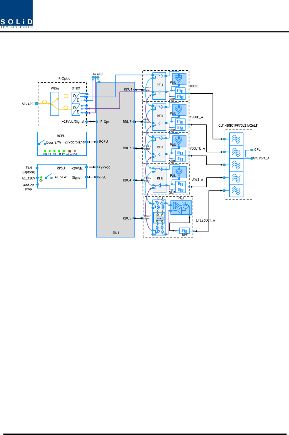
3.1 General
ThefollowingfigureshowstheblockdiagramofHERCULES‐SRemoteUnit.
Figure3.1–RemoteUnitBlockDiagram
Therearemanycomponents;
R‐Optic:RemoteOpticalUnit
RCPU:RemoteCentralProcessorUnit
RPSU:RemotePowerSupplyUnit
RDU1‐5:RemoteDriveUnit
CU:CombiningUnit
Confidential & Proprietary 13/30
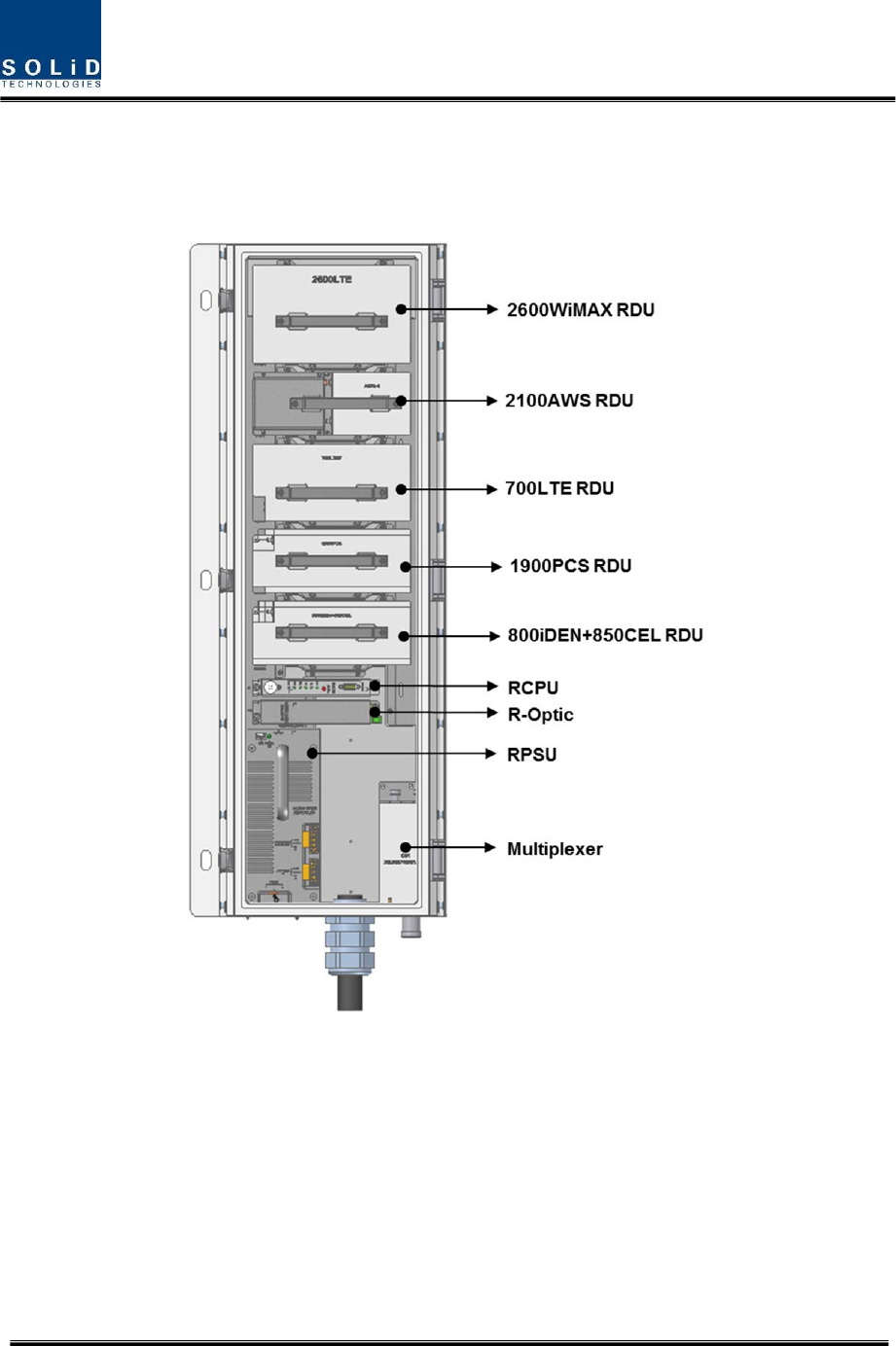
3.2 ComponentofHERCULES‐SRemoteUnit
ThefollowingfigureshowsinternalconfigurationofRemoeUnitwithfullyRFequipped.
Figure3.2–InsideofRemoteUnit
RemoteUnitreceivesTXopticalsignalsfromHead‐EndandconvertsthemintoRFsignals.Theconverted
RFsignalsareamplifiedthroughHighPowerAmpinacorrespondingRDU,combinedwithMultiplexer
moduleandthenradiatedtotheantennaport.
WhenreceivingRXsignalsthroughtheantennaport,thisunitfiltersout‐of‐bandsignalsina
correspondingRDUandsendstheresultstoRemoteOpticModuletomakeelectronic‐optical
conversionofthem.Afterconverted,thesignalsaresenttoaupperdeviceofODU.ROUcanbe
equippedwithuptofiveRDUs(RemoteDriveUnit)

Confidential & Proprietary 14/30
ThefollowingtabledescribescomponentsonRemoteUnit
UnitDescri
p
tion
RDU+BPFx5
RemoteDriveUnit
Filterandam
p
lif
y
TXsi
g
nals
Filterandam
p
lif
y
RXsi
g
nals
Removeothersi
g
nalsthrou
g
hBPF
RPSU
RemotePowerSu
pp
l
y
Unit
In
p
ut
p
ower:120VAC+
/
‐10%
Out
p
ut
p
ower:+29VDC
R‐OPTIC
RemoteO
p
tic
MakeRFconversionofTXo
p
ticalsi
g
nals
;
ConvertRXRFsi
g
nalsintoo
p
ticalsi
g
nals
;
Com
p
ensateso
p
ticalloss
CommunicateswithBIU
/
OEUthou
g
htheFSKmodem
10dBoo
p
ticallinkbetweenODUandROU
FiberConnector:SC
/
APCConnector
FiberT
yp
e:Sin
g
leModeFiber
O
p
ticalWavelen
g
th:1310
/
1550WDM
RCPU
RemoteCentralProcessorUnit
Controlssi
g
nalofeachunit
MonitorsBIU
/
ODU
/
OEUthrou
g
hFSKcommunication
Multiplexer
Multi
p
lexer
CombineTXsi
g
nalsfrom5RDUs
;
DistributeRXsi
g
nalsto5RDUs
;
Enable
y
outouseasin
g
leantenna
p
ort
ROUEnclosure
Enclosuretosatisf
y
IP66
HorizontalorVerticalMount
Ceilin
g
orPoleMount
InputSIUIn
p
utS
y
stemInterfaceUnit
Distributes
p
owerandsi
g
nalstoeachmodule
OutputSIUOut
p
utS
y
stemInterfaceUnit
Interfacin
g
withmulti
p
lexer
Confidential & Proprietary 15/30
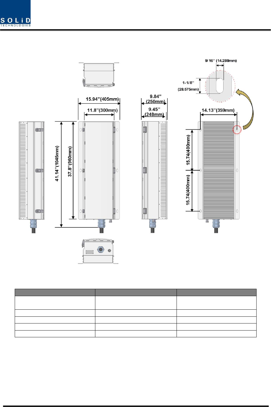
3.3 Dimension
Figure3.3–RemoteUnitDimension
ITEMSPECIFICATION REMARK
Size(Width,Height,Depth)405x960x250mm/
15.94’’x37.8’’x9.84inchIncludingBracket
Weight51kg/112lb Fullyloaded
PowerConsumption390W Fullyloaded
OperatingTemperature‐25to+55
°
C /‐13to131
°
FAmbientTemperature
OperatingHumidity0to90%,non‐condensing

Confidential & Proprietary 16/30
Section4 System
Installation
5.1RemoteUnitInstallation

Confidential & Proprietary 17/30
Thischapterdescribeshowtoinstalleachunitandopticalcables,alongwithpowercablingmethod.In
detail,thechapterdescribeshowtoinstallshelvesorenclosuersofeachunit,PowerCablingmethod
andOpticCablingandRFInterface.
Theneededaccessoriesandtoolsarelistupinthebelowtable.
StepsforinstallationAccessoriesIncludedToolRemark
RemoteEnclosureInstallationM12Bolt(6EA)XSpanner(19mm)
Power&
OpticConnection
Cableforcompression
connector(HBG‐114‐1)
XInstallationmanual
providedbyRFS
Optic:SC‐APCX
Power:
20020517M031B01LF(FCI)
O“4mm”Screw
driver(forslotted
screw)
AntennaConnectionDIN7/16CONNECTOR
(Male),Coaxialcablefor
DIN7/16
X‐
Confidential & Proprietary 18/30
4.1 REMOTEUNITInstallation
4.1.1 REMOTEUNITEnclosureinstallation
REMOTEUNITisdesignedtobewater‐anddirt‐proof.TheunithasthestructureofOne‐Bodyenclosure.
Itsatisfieswater‐proofandquake‐proofstandardsequivalentofNEMA4.
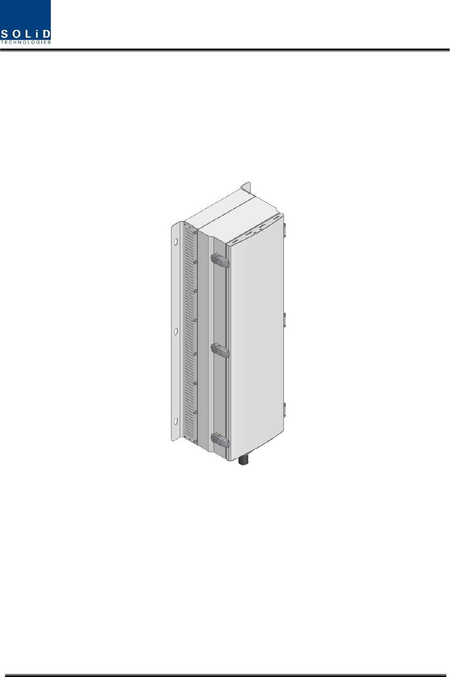
REMOTEUNITcanbemountedoneitherceilortheWall.Basically,REMOTEUNIThasbothofaWall
MountBracket.ThefollowingshowsdimensionofthefixingpointfortheWallMountBracket.
Figure4.1–ExteriorofRemoteUnit
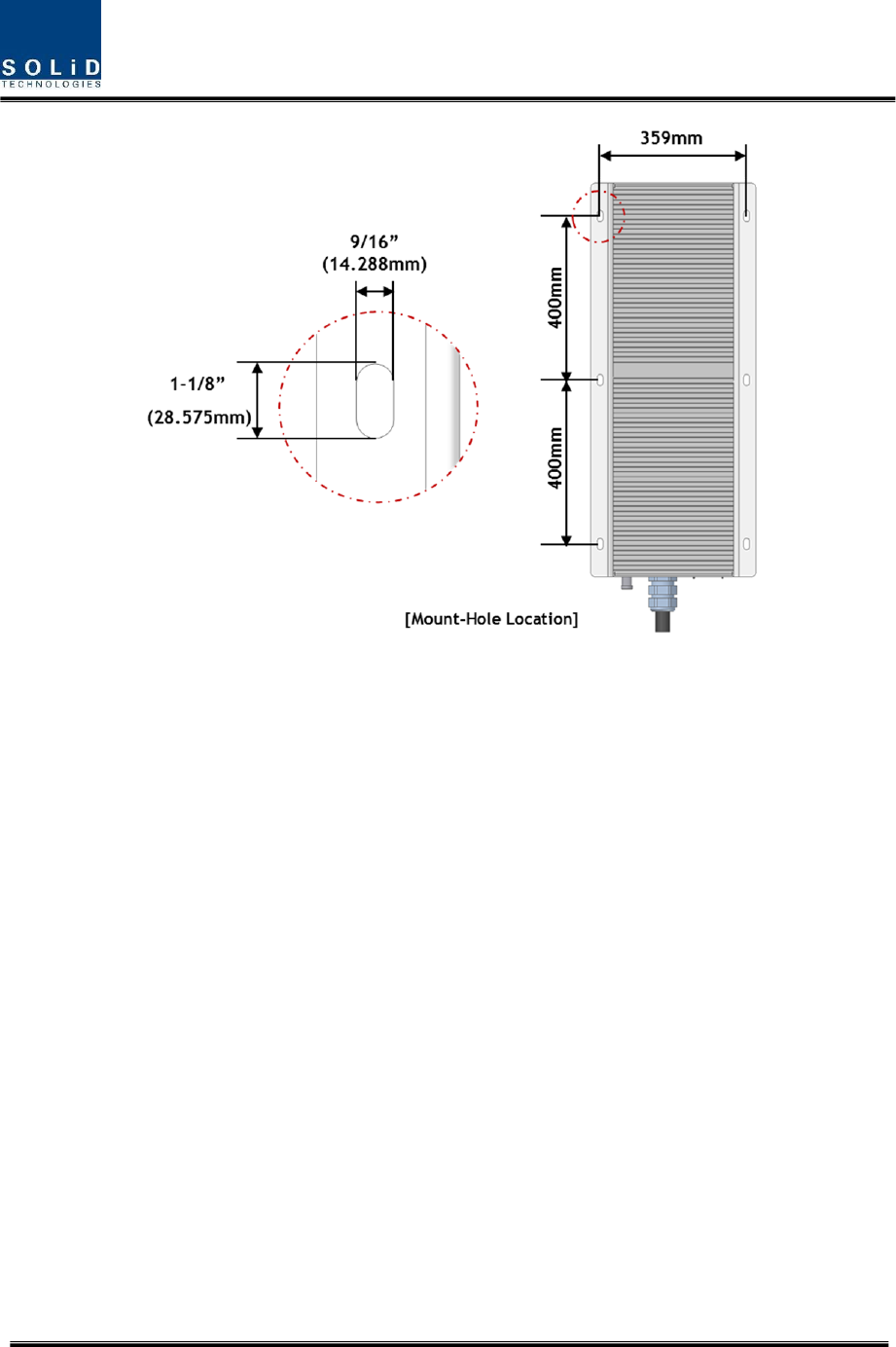
Confidential & Proprietary 19/30
Figure4.2–DimensionusedtoinstallREMOTEUNITontheWALL
Confidential & Proprietary 20/30
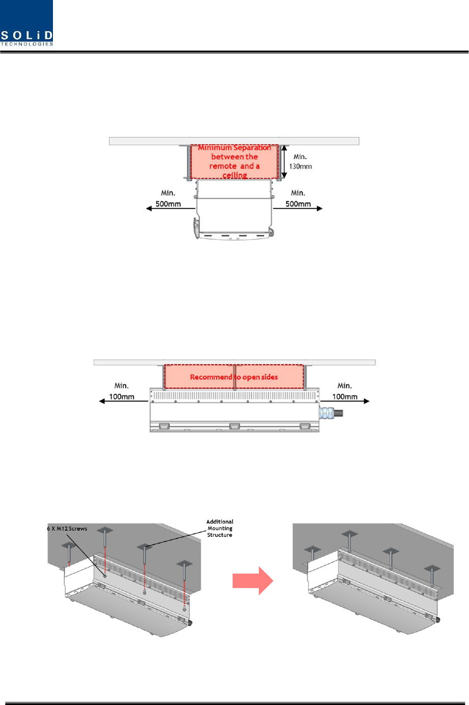
REMOTEUNITCeilMountInstallation
Forhorizontalinstallation,minimumseparationdistanceof130mmisrecommendedasshowninthe
belowfigure.
Figure4.3–HorizontalInstallation
Theinstallationclearancesecuressystemreliability.
Selecttherightlocationwheretheremoteunitcanbeinstalledsecurelyconsideringweightload
capacity,therewouldbeadditionalmountingstructurescanbeappliedasshowninthebelowfigure
Figure4.4–InstallationClearance
MountremoteunittothemountinglocationusingM12screws.Differentlengthandmaterialtypeof
theM12screwscanbeselecteddependingonmountingcondition
Figure4.5–HowtoInstallRemoteUnit
Confidential & Proprietary 21/30
4.1.2 RemoteUnitPowerCabling
RemoteUnitsupportsonlyAC120Vofinputpower.
ThefollowingfigureshowsconfigurationofpowersupplyforAC120V.
LugNamingRPSUTerminalnamingRemark
AC_HAC‐H
AC_NAC‐N
GNDFG
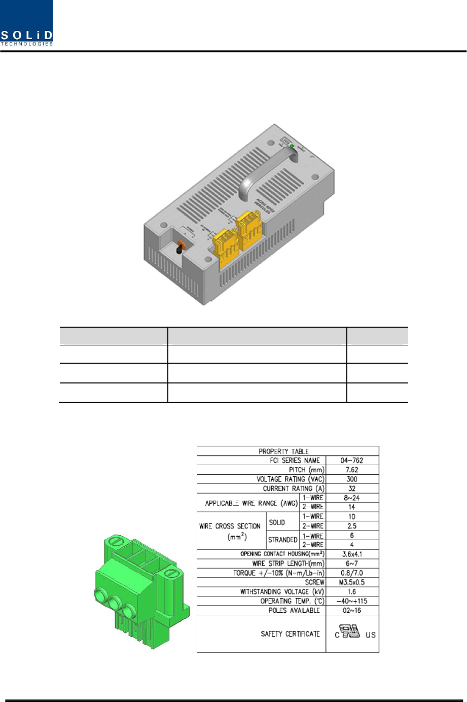
Theprovidedconnectoris“20020517M031B01LF”ofFCIvendor.Thefollowingtableshowsmain
specificationofthisconnector.
Confidential & Proprietary 22/30
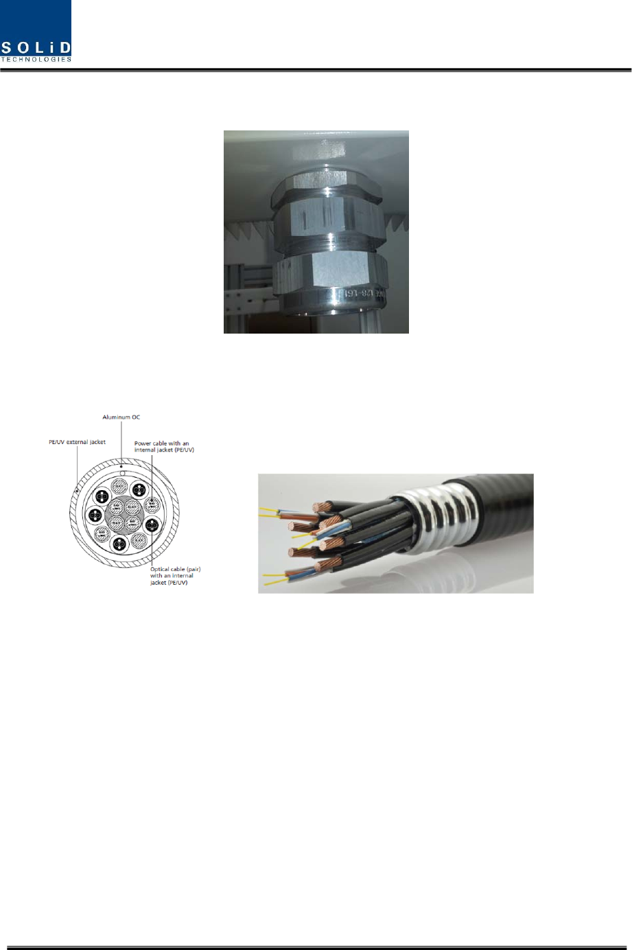
Inordertoinstallthepowerconnection,firstconnectHBG‐114‐1connector(RFS)onholeatbottomof
enclosure.ThisHBG‐114‐1connectorhas36.0mmdiameterandmadeofaluminum.
TherecommendedcableisHYBRIFLEX(HB114‐1‐08U5‐S6F,RFS),whichconsistSM6F/O,5DCpairsand
8AWG.Thecable’souterconductorarmorhavecorrugatedaluminumwithexternaljacketmadeof
polyethylence(PE).
Theouterconductorgroundinghavearoletoeliminatetypicalgroundingrequirementandsaveson
installationcosts.Afterstrippingexternaljacketofcableusingtoolintheproperandthenconnectitto
HBG‐114‐1connector.FastenexternalhexnutofHBG‐114‐1connecttobefixed.
Thepowerinstallationproceduresareasbelow
1. Takeoff20020517M031B01LFconnectorfromRPSU
2. TherecommendedwiresizeisbelowAWG#10
3. Select3wireamong8AWGs
4. TheproperstriplengthofAWGcableis6~7mm
5. Andinsertthiswireintodesignatedpositionofconnector
6. SecureM3.5screwusingscrewdriverwithscrewtype“–“
7. ConnectthisconnectoronRPSUandsecurescrewusingscrewdrivertofix

Confidential & Proprietary 23/30
CheckiftheconnectionisthesameasoneseeninthetableaboveandmakesuretoturnthepowerON.
CAUTION
DOUBLEPOLE/NEUTRALFUSING
Groundcablewithgreen/yellowcoloramong3wiresofpowercables(HOT,NEUTRAL,GND)
shouldbefixedatheatsinkofenclosurebeforeconnectingwithconnectortopreventdamagefrom
pullingoutbyexternalstrongforce.Atthistime,secureM3.5screwusingscrewdriverwithscrewtype
“+“.TherecommendedAWGis#10.
Confidential & Proprietary 24/30
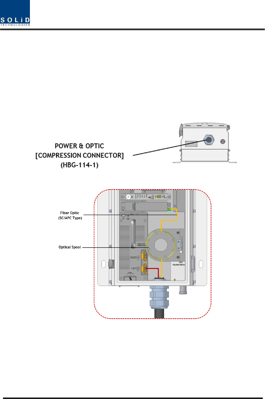
4.1.3 RemoteUnitOpticalCabling
REMOTEUNITmakesoptical‐electronicconversionofTXsignalsfromupperODUmakeselectronic‐
opticalconversionofRXsignals.REMOTEUNIThasoneopticalmoduleinit.AsWDMisinstalledinthe
R_OPTICmodule,twopiecesofwavelength(TX:1310nm,RX:1550nm)canbesent/receivedwithone
opticalcoreatthesametime.REMOTEUNIThasSC/APCofopticaladaptortype.
Foropticaladaptor,SC/APCtypecanbeused.Topreventtheopticalaccesspartfrombeingmarredwith
dirt,itshouldbecoveredwithacapduringmove.Whendevicesareconnectedthroughopticalcables,
youneedtoclearthemusingalcohocoltoremovedirt.
OpticalcablesshouldbeinsertedintoOpticPortoutsideofREMOTEUNIT.Usinganopticalspoolin
REMOTEUNIT,youneedtocoilaroundoneortworollofcablestobeconnectedwiththeoptical
adaptorofROPTIC.
Atthistime,curvatureoftheopticalcableshouldbeatleast10Øtopreventinsertionlossfrombeing
increased.
Confidential & Proprietary 25/30
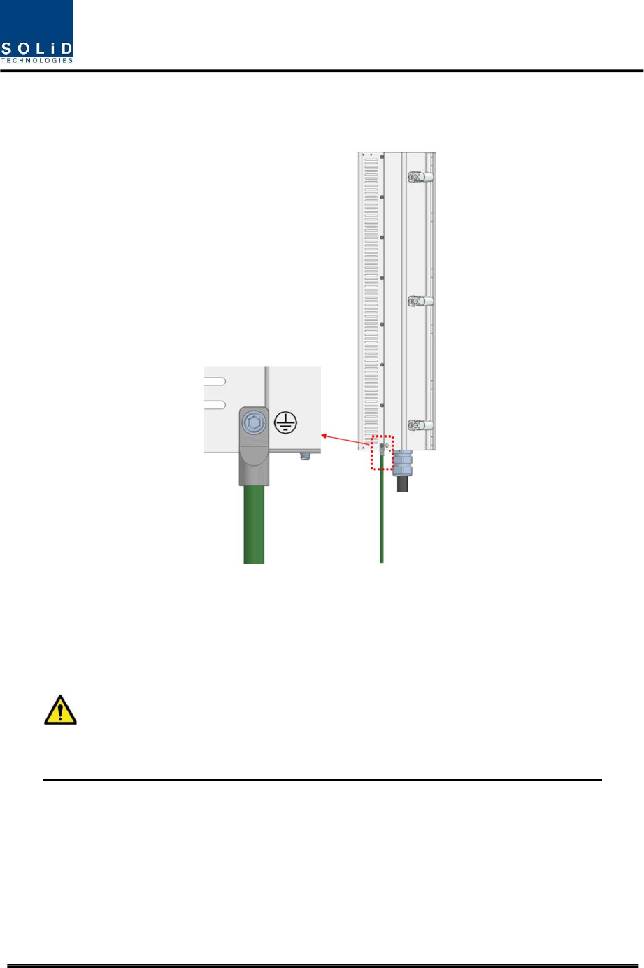
4.1.4 GNDTerminalConnection
TheGroundTerminalislocatedatthelefsideofRemoteUnit.
Groundingmustbecarriedout.Connectanearth‐bondingcabletothegroundingconnctionprovidedat
theoutsideoftheRemoteUnit(atleftside).
Afterlosseningthehexbolt,connecttheearth‐bondingcablebetweentheenclosureandhexbolt.Then,
fastenallpartsagainwiththehexbolt.
Roundterminalslocatedonthesideofa0.75mm2(18AWG)ormorewiresUsingpermanently
connectedtoearth(green/yellowcolor)

Confidential & Proprietary 26/30
4.1.5 CoaxialcableandAntennaConnection
Thecoaxialcableswhichareconnectedtoantennadistribuednetworkconnecttoantennaportof
REMOTEUNIT.Beforeconnection,checktheVSWRvalueofcoaxialcablewhetheritiswithin
specificationusingSITEMASTER.
Atthistime,checkiftheReturnlosshaveabove14dBorVSWRhavebelow1.5
Thepartofantennaconnectionfastentoportnottobeloossenedandnottobeinjectedthedustyand
insects
TheantennaconnectedtoREMOTEUNITisonlyservicedininbuilding

Confidential & Proprietary 27/30
Section5
SystemSpecifications
6.1PhysicalSpecifications
6.2RFPerformance
6.3Certification

Confidential & Proprietary 28/30
5.1 PhysicalSpecifications
ParameterROU
RFConnectors
(
1
)
7/16DIN‐t
yp
e,female
SerialInterfaceconnector
(
1
)
RS‐2329‐
p
in
D‐sub,male
Fiberconnector
(
1
)
SC/APCforODU
LEDAlarmandStatusIndicator
PowerLED
TXLED
RXLED
LDLED
PDLED
ALARMLED
RESETButton
ACPower
NormalRan
g
e:120VAC
50/60Hz
O
p
eratin
g
ran
g
e
108~132VAC,50/60Hz
Powerconsumption390W
(
ROUw/5RDUs
)
EnclosureDimensions(mm)
405x960x250mm/
15.94’’x37.8’’x9.84inch
Wei
g
ht
(
FullLoad
)
51k
g
/112lb
Material
(
Exterior
)
2mmAluminum
Safet
y
ULLabeled
CertificationsUL,FCC
Confidential & Proprietary 29/30
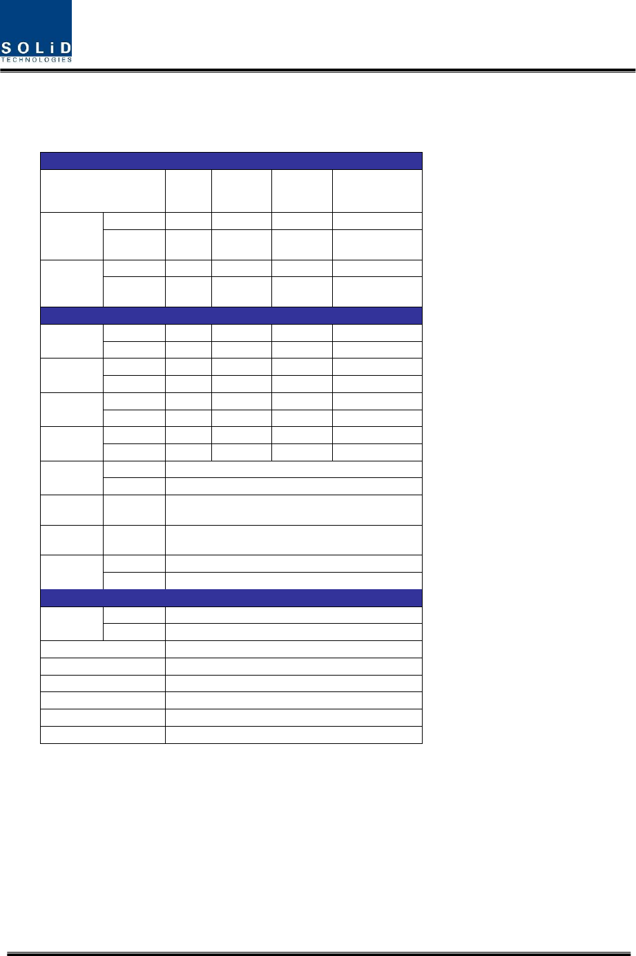
5.2 RFperformance
Supported Services
Supported Services 700LTE
Full Band
800
Sprint/850
Cellular
1900
PCS
2100
AWS
Frequency
Range
Tx (MHz) 728-756 862-894 1930-1995 2110-2155
Rx (MHz) 698-716
777-787 817-849 1850-1915 1710-1755
Bandwidth
Tx (MHz) 28 32 65 45
Rx (MHz) 18
10 32 65 45
RF Parameters
Input Power
Tx (dBm) -20 to +10 -20 to +10 -20 to +10 -20 to +10
Rx (dBm) ≤ -50 ≤ -50 ≤ -50 ≤ -50
Output Power Tx (dBm) 37 37 37 37
Rx (dBm) 0 0 0 0
System Gain
Tx (dBm) 57 57 57 57
Rx (dBm) 50 50 50 50
System Delay
Tx < 8µs < 8µs < 8µs < 8µs
Rx < 8µs < 8µs < 8µs < 8µs
Impedance Tx (ohm) 50
Rx (ohm) 50
Spurious
Emissions Tx ≤ -13dBm @ 9kHz – 5GHz
Out of Band
Attenuation Rx ≤ 45dB @ F_edge ± 1MHz offset
Gain Control
Range/Step
Tx 25dB/step 1dB
Rx 20dB/step 1dB
Optical
Optic
Wavelength
Tx 1310nm WDM
Rx 1550nm WDM
Optic Link AGC Above 10dB
Optic Link Loss Max 10dBo
Noise Figure 8dB Max
Optical Connector SC-APC (Single Mode Fiber)
RF Connector DIN-F (Common Output), N-F (UHF/VHF and AOR)
Monitoring Port -30dB (SMA Female)

Confidential & Proprietary 30/30
5.3
Certification
TitleStandards Remarks
Environmental
Tem
p
eraturean
g
e‐25°Cto+55°C/‐13to131
°
FAmbientTem
p
erature
Humidit
y
Ran
g
e0%~90%Non‐condensin
g
TransportationETSIEN300019‐1‐2IEC60721‐3‐2Class2.3Classes2K2/2M2
StorageETSIEN300019‐1‐1IEC60721‐3‐1Class1.2Classes1K2/1M3
Sealing(Remote
Unit)
IEC60529EN60529IP66Complaint
Productsafet
y
Typeapprovalsand
certifications
NorthAmericaUL60950‐1,2ndEditionCSAC22.2No.
60950‐1‐07,2ndEdition,CSAC22.2No.
ULCertification
NorthAmerica
FCCPart24SubpartDandPart90SubpartI
FCCPart22SubpartHandPart27SubpartC
FCCPart24SubpartEandPart27SubpartC
FCCCertification
CanadaRSS‐131(ISSUE2)ICCertification
EMC
EmissionNorthAmericaFCCPart15Sub
p
artB,ClassAFCCVerification
MTBF
MeanTime
BetweenFailures
NorthAmericaTelcordiaSR‐332Issue2
Fits:(FailureUnit)MTBF=
ROUFailureRate=11,823MTBF=9.65Years Full
y
loadedROU