SOLiD SRDR7080A W6USRDR7080A User Manual Responder
SOLiD, Inc. W6USRDR7080A Responder
UserManual.wiki
>
SOLiD
>
SRDR7080A User Manual
Class A_SOLiD Responder_User Manual_Rev.1
Navigation menu
Upload a User Manual
Namespaces
Wiki Guide
HTML
PDF
Info
Views
User Manual
Discussion / Help
Navigation

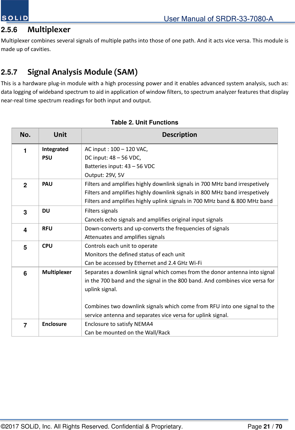
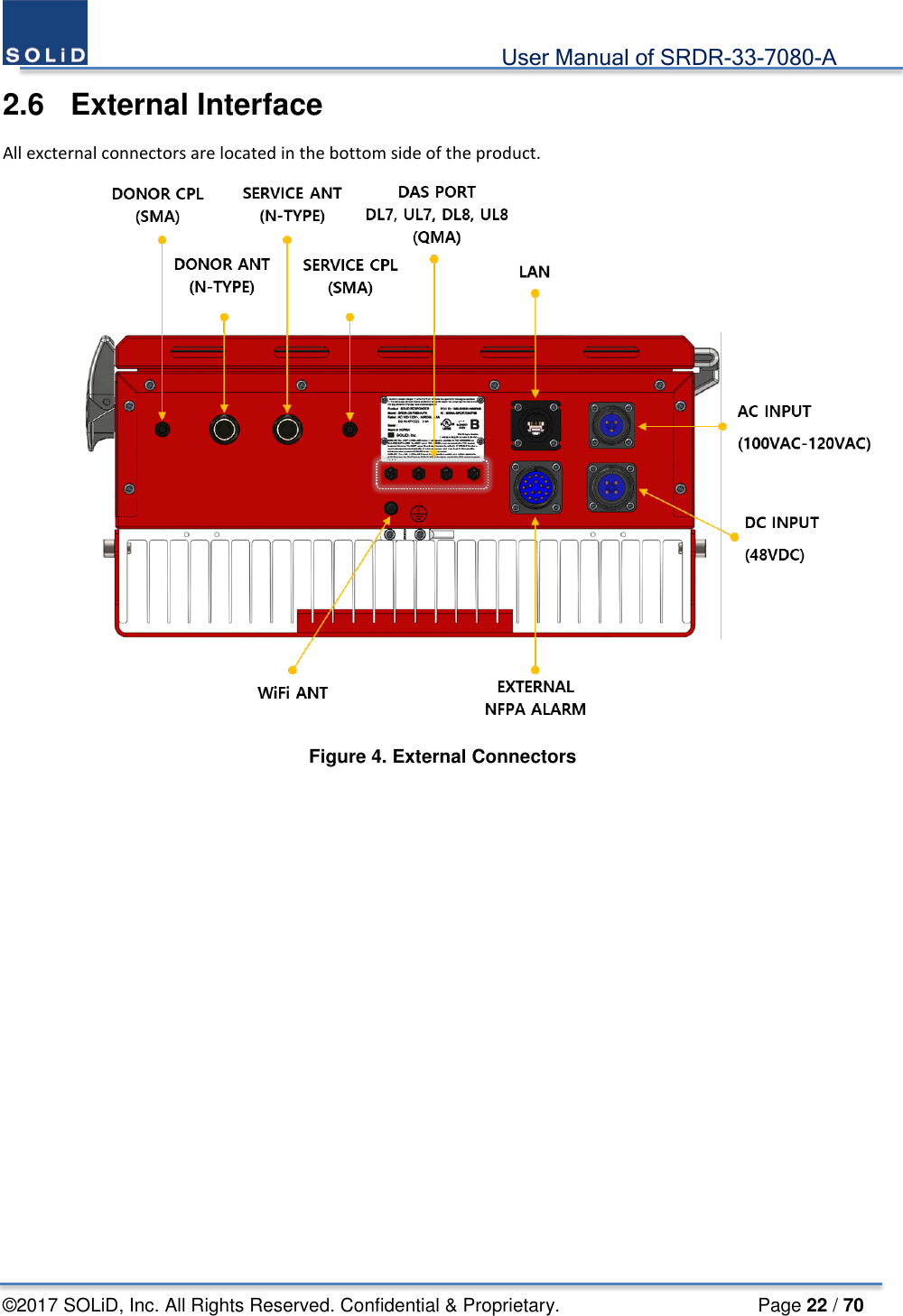
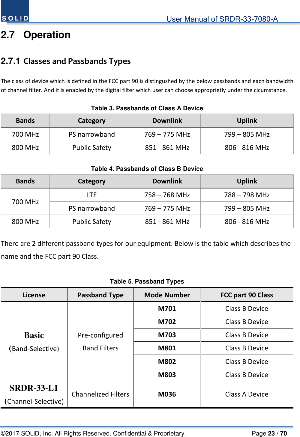
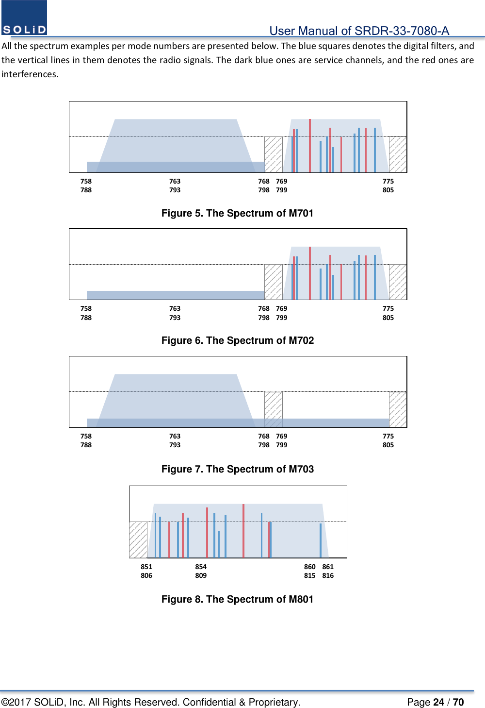
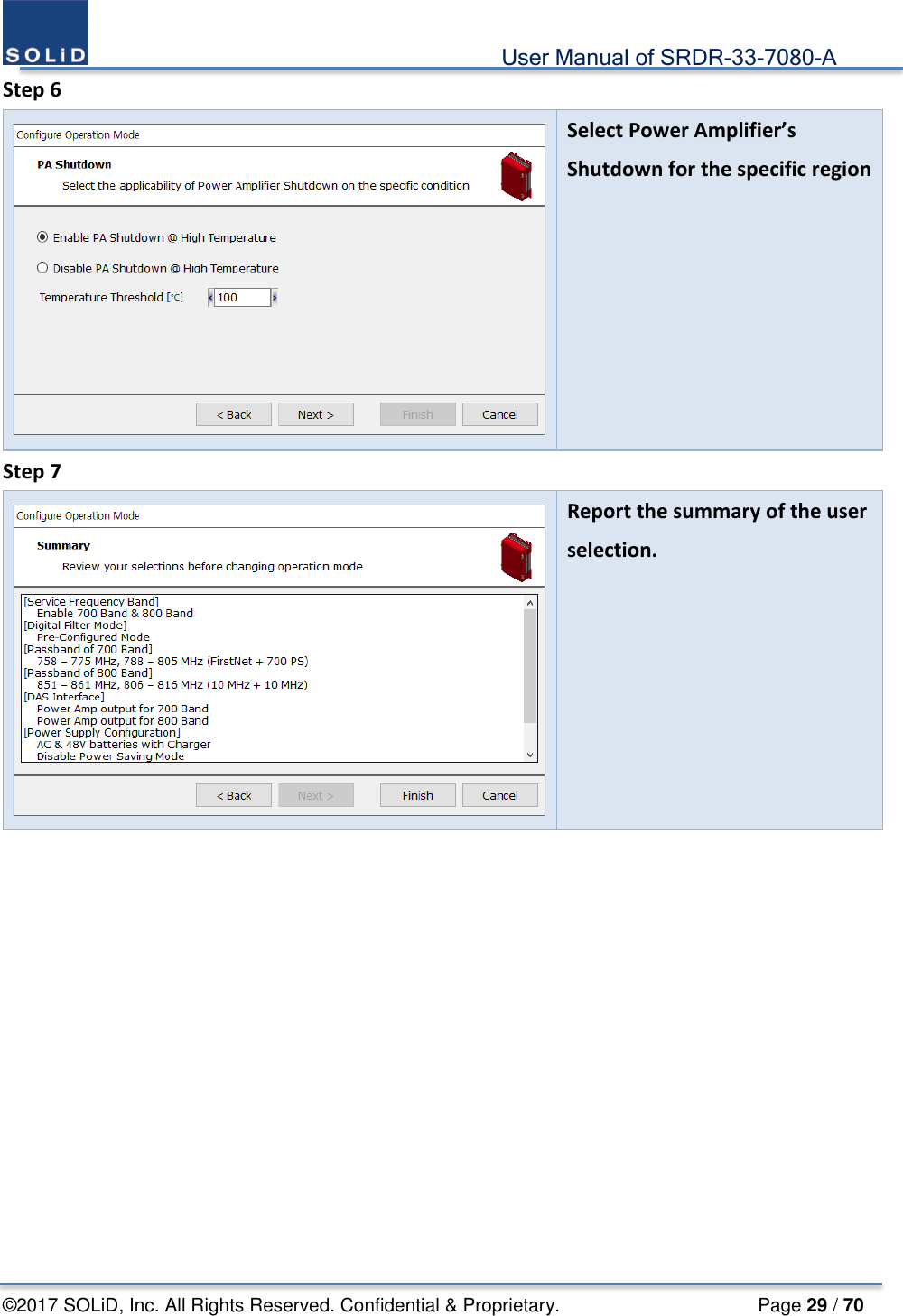
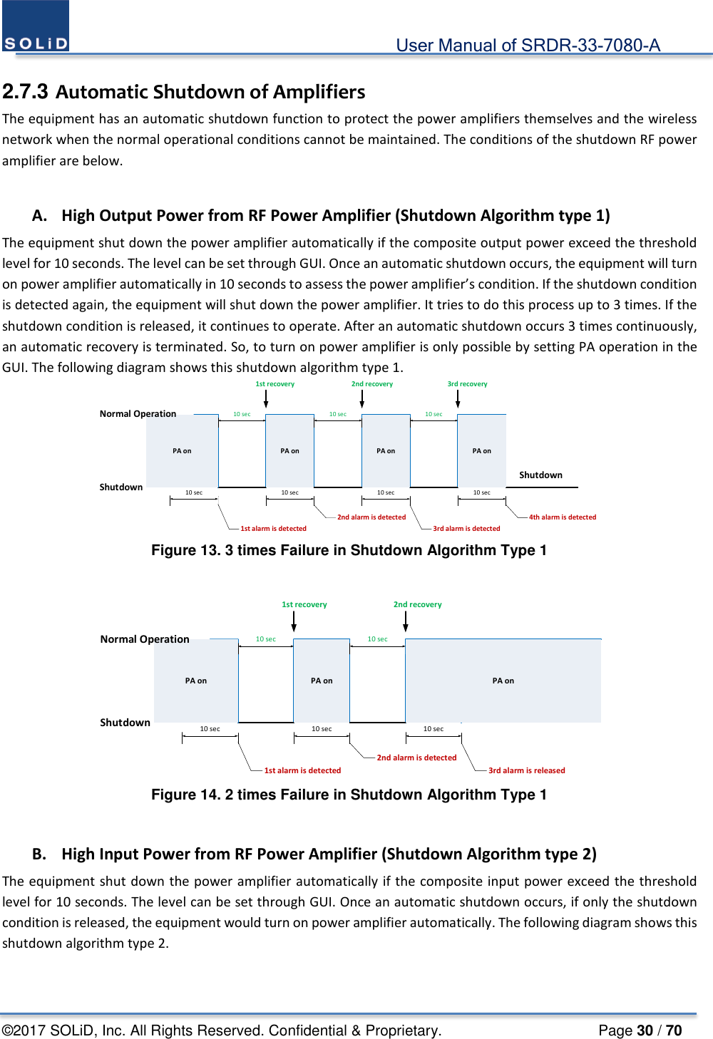
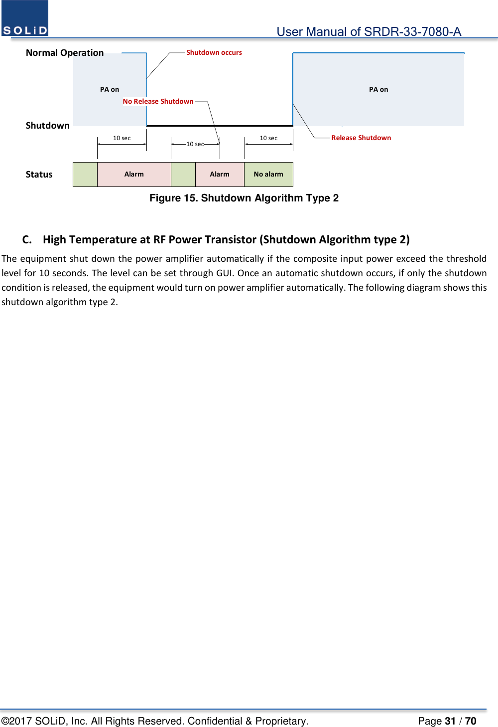
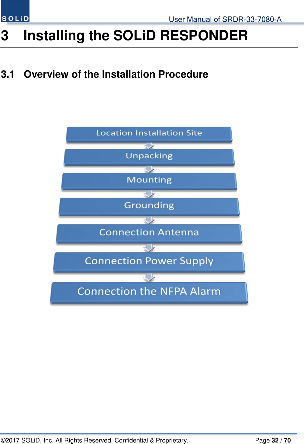
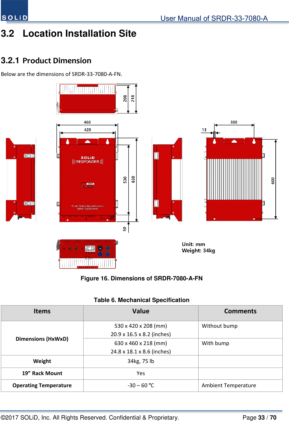
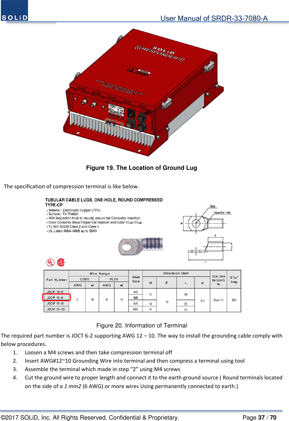
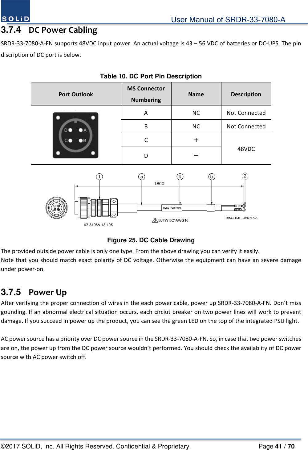
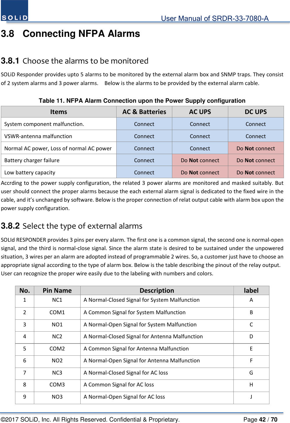
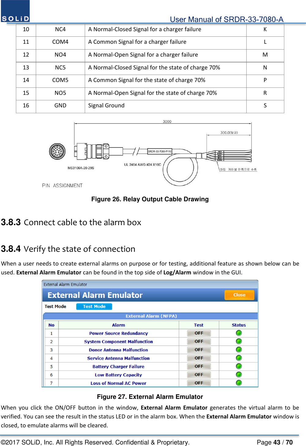
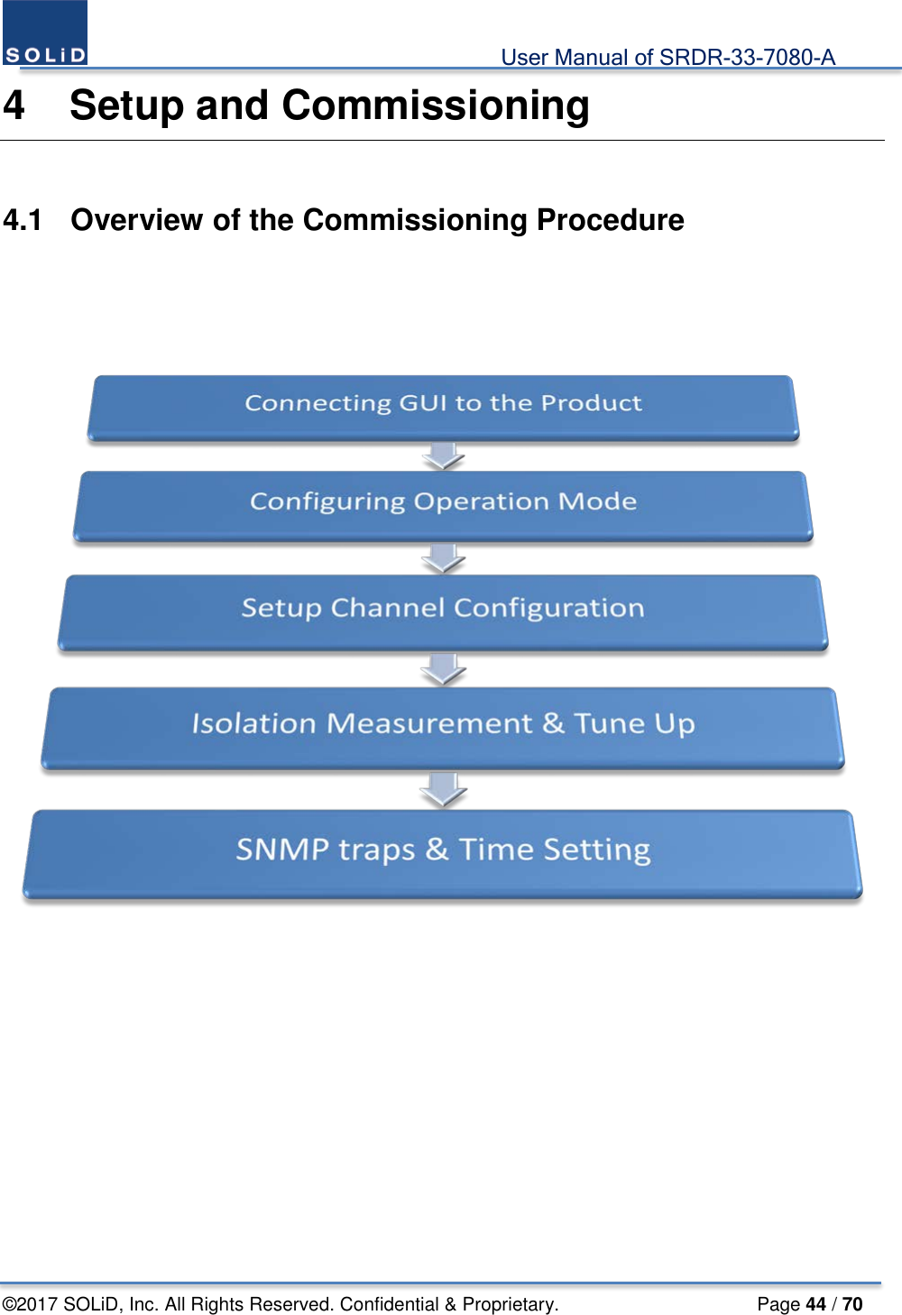
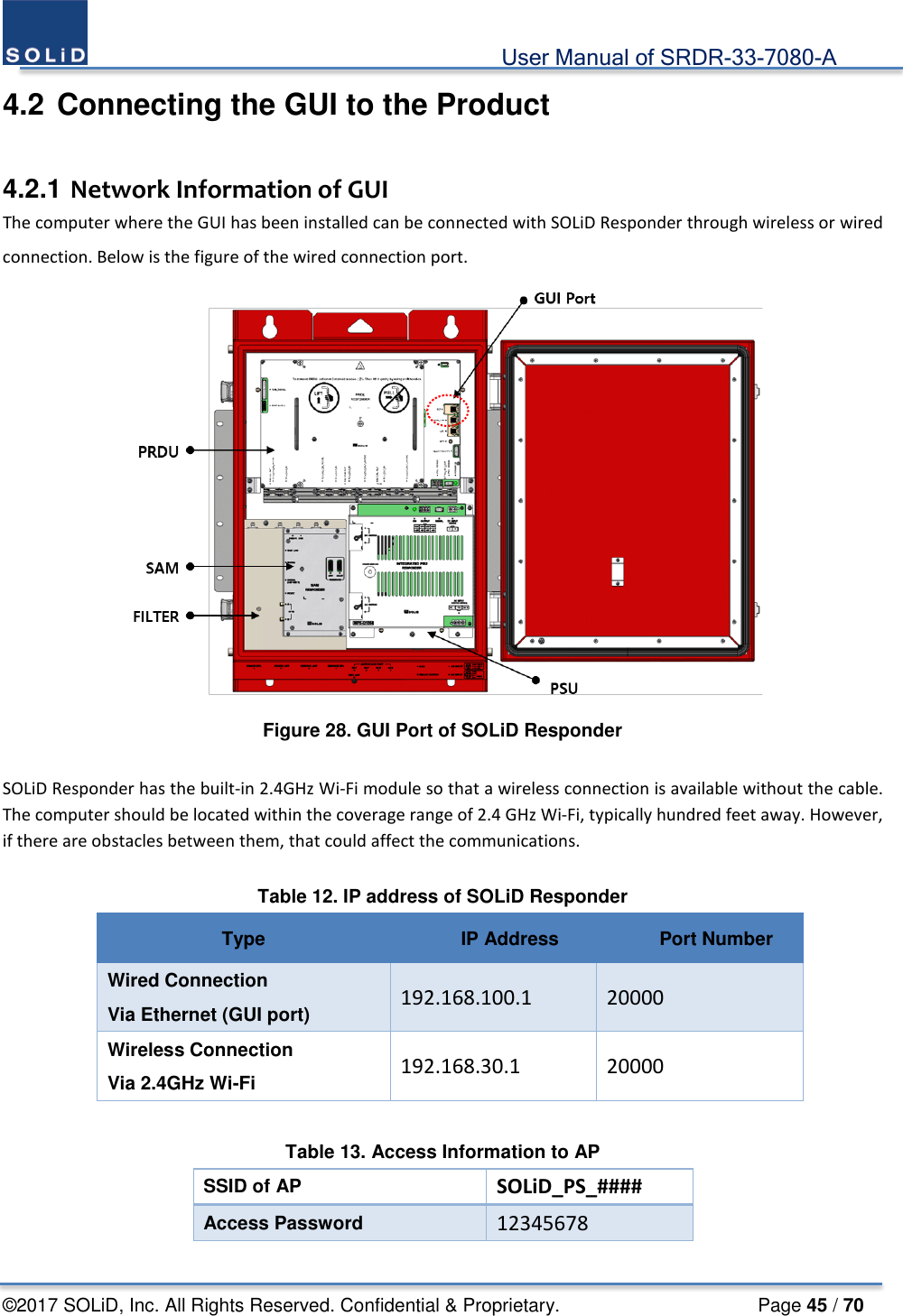
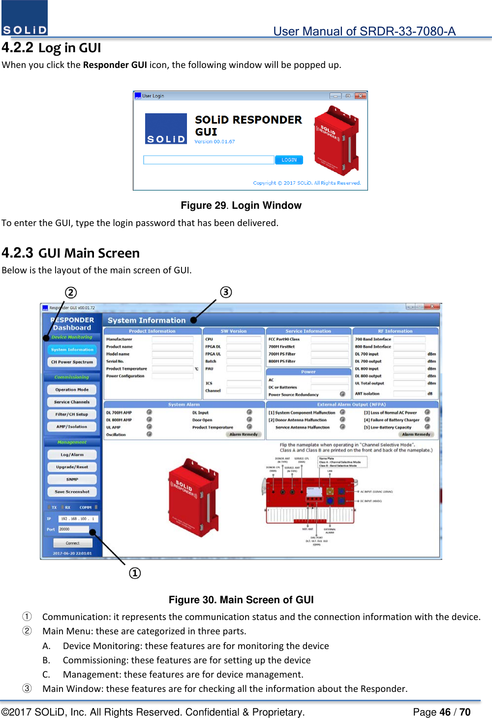
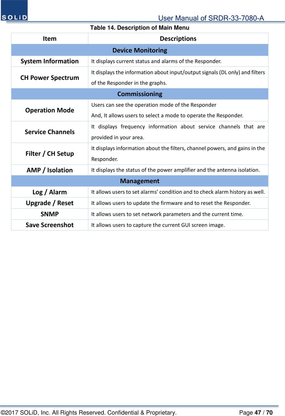
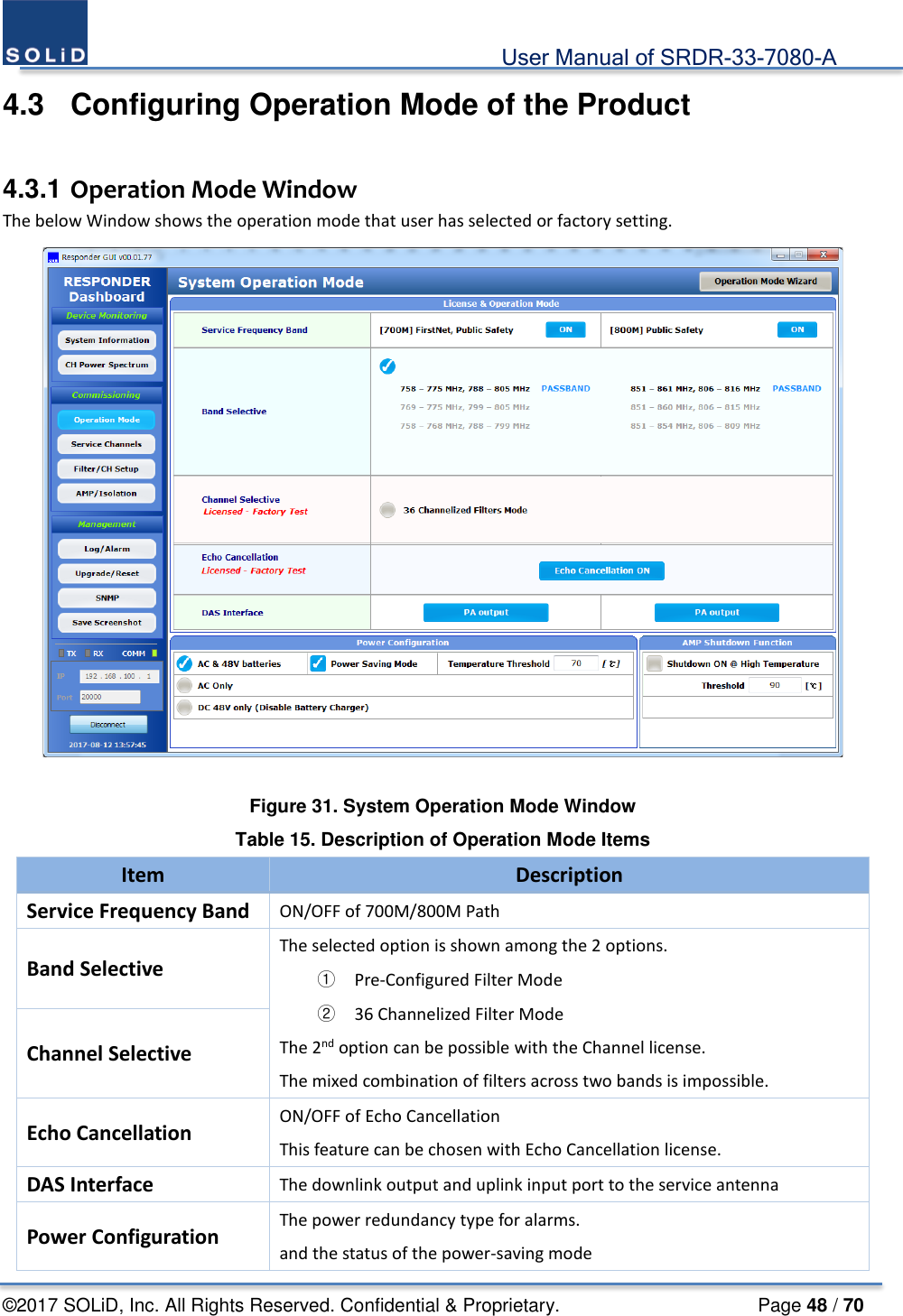
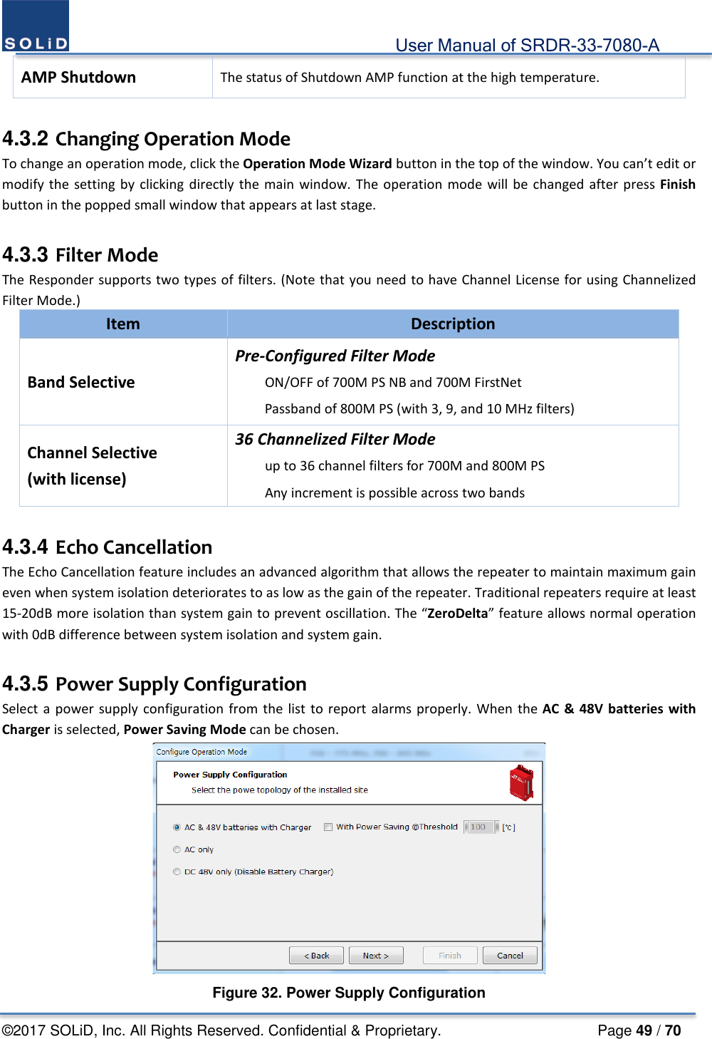
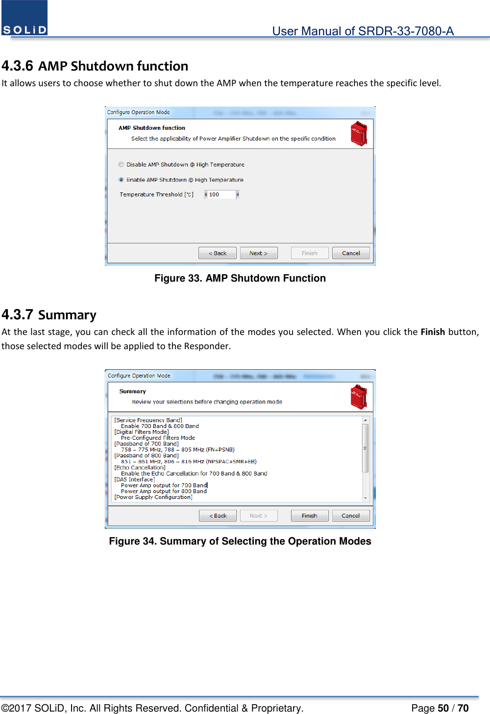
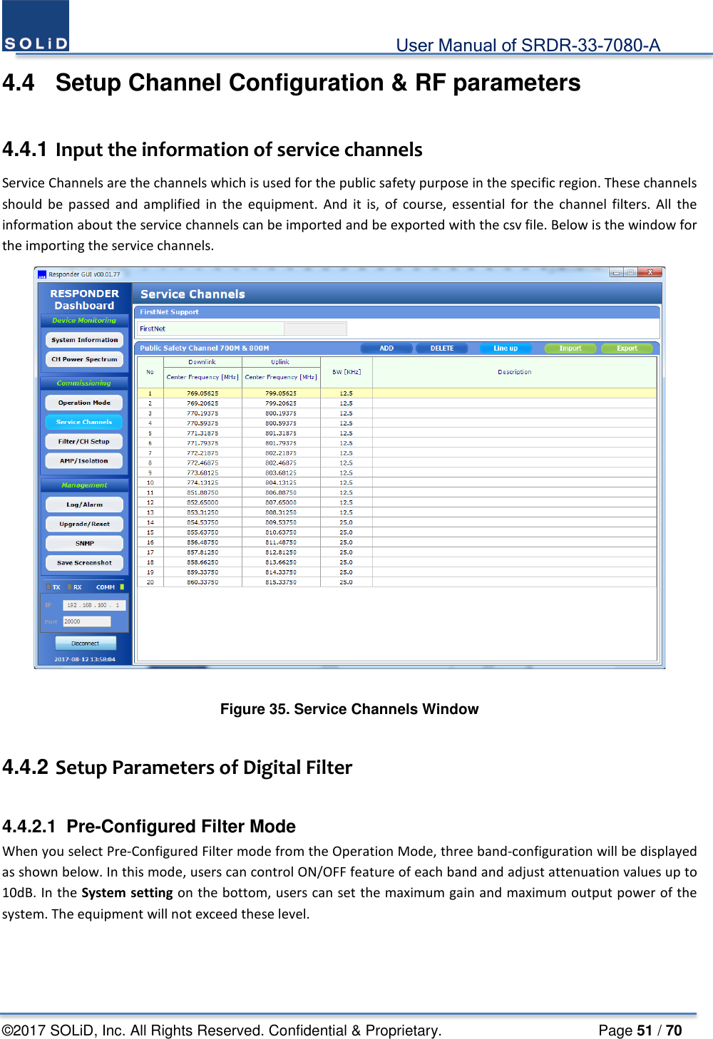
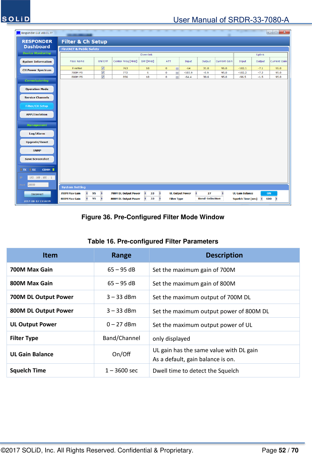
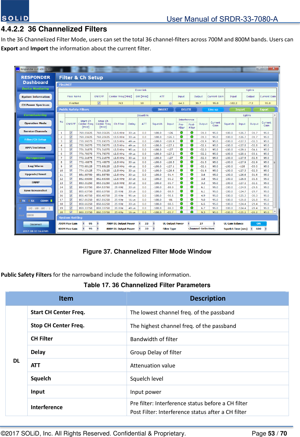
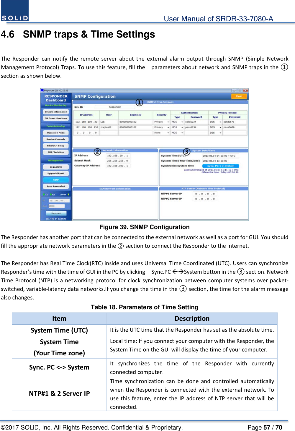
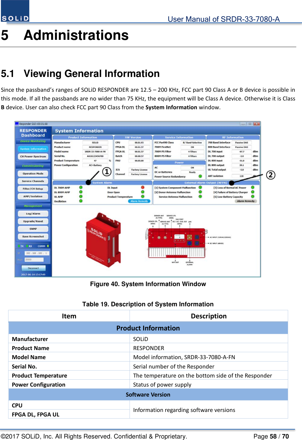
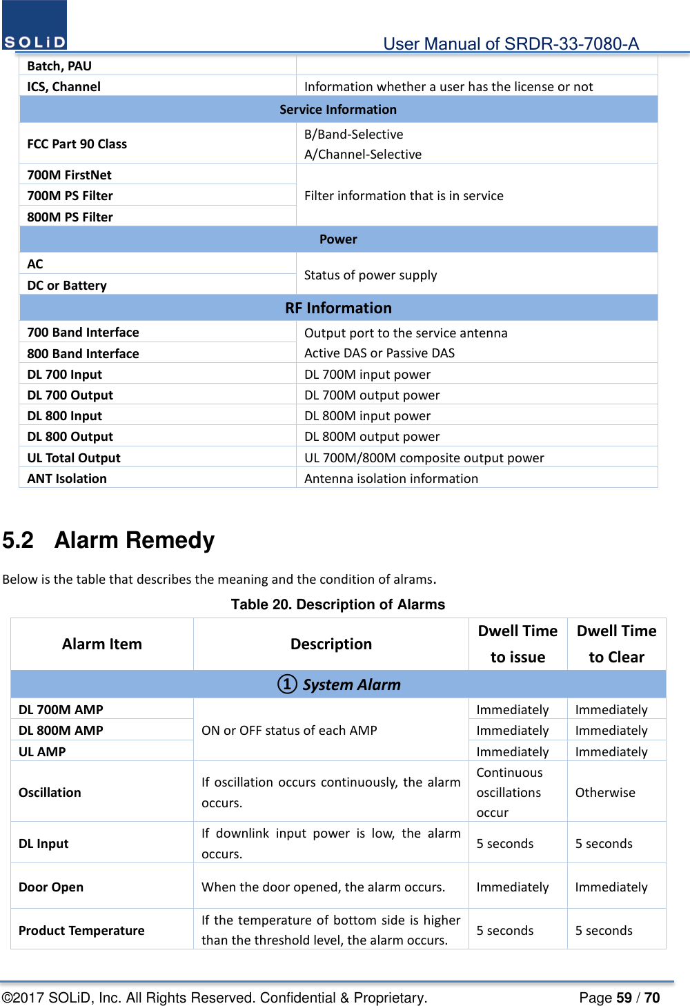
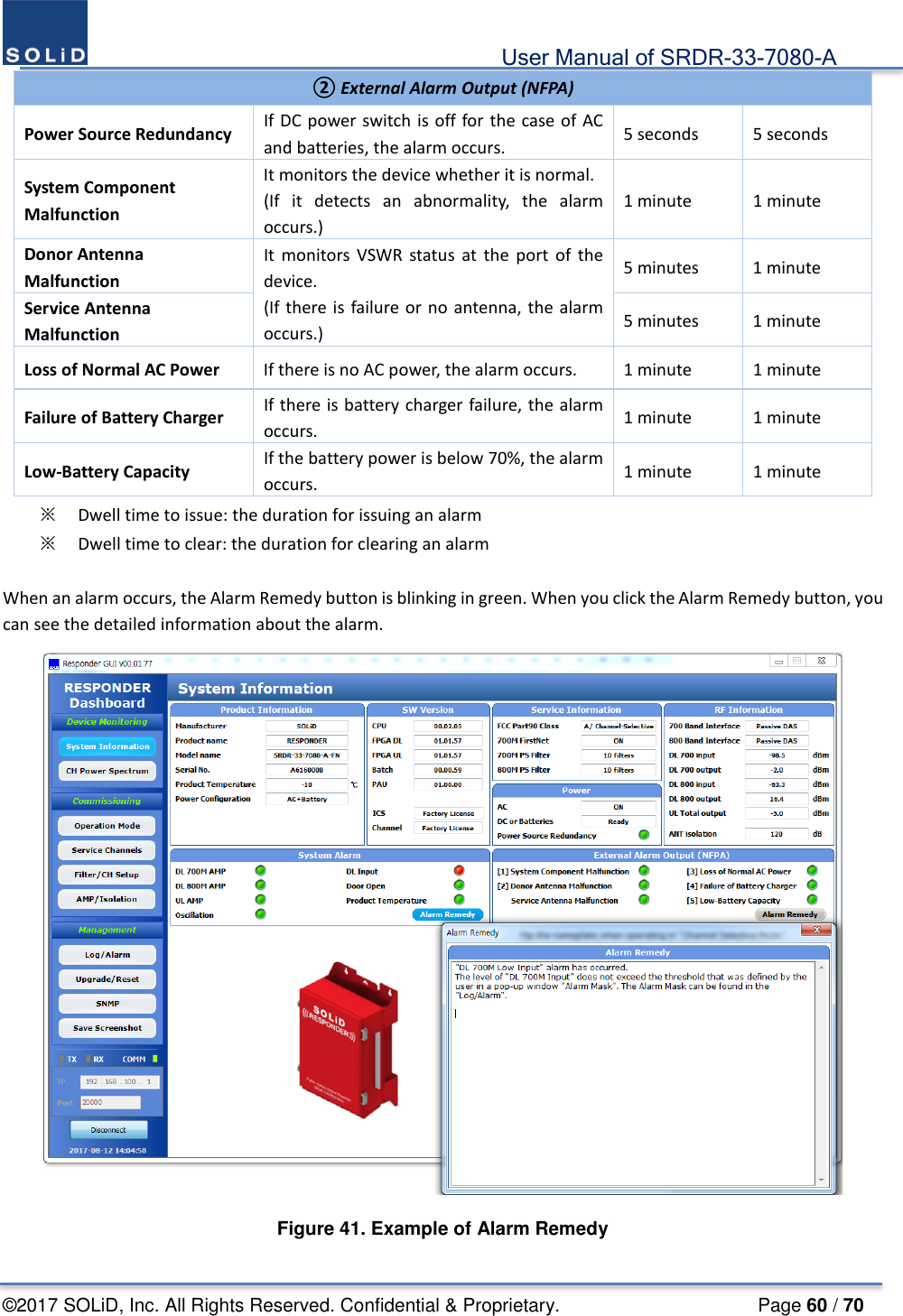
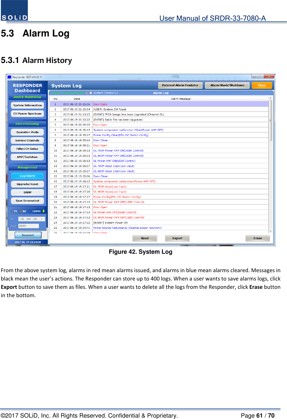
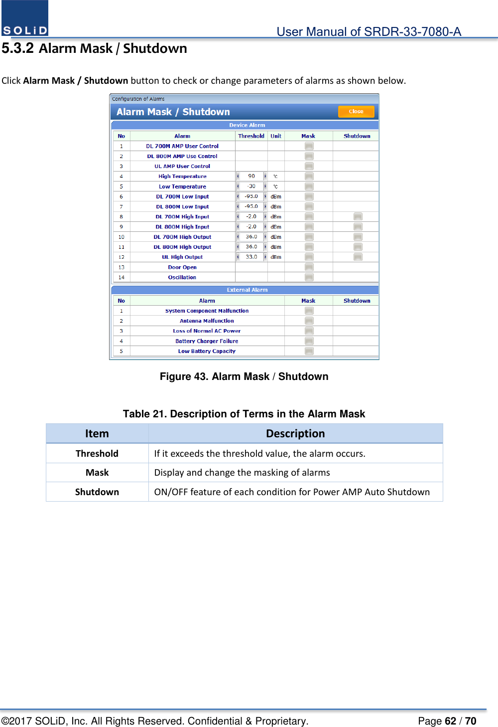
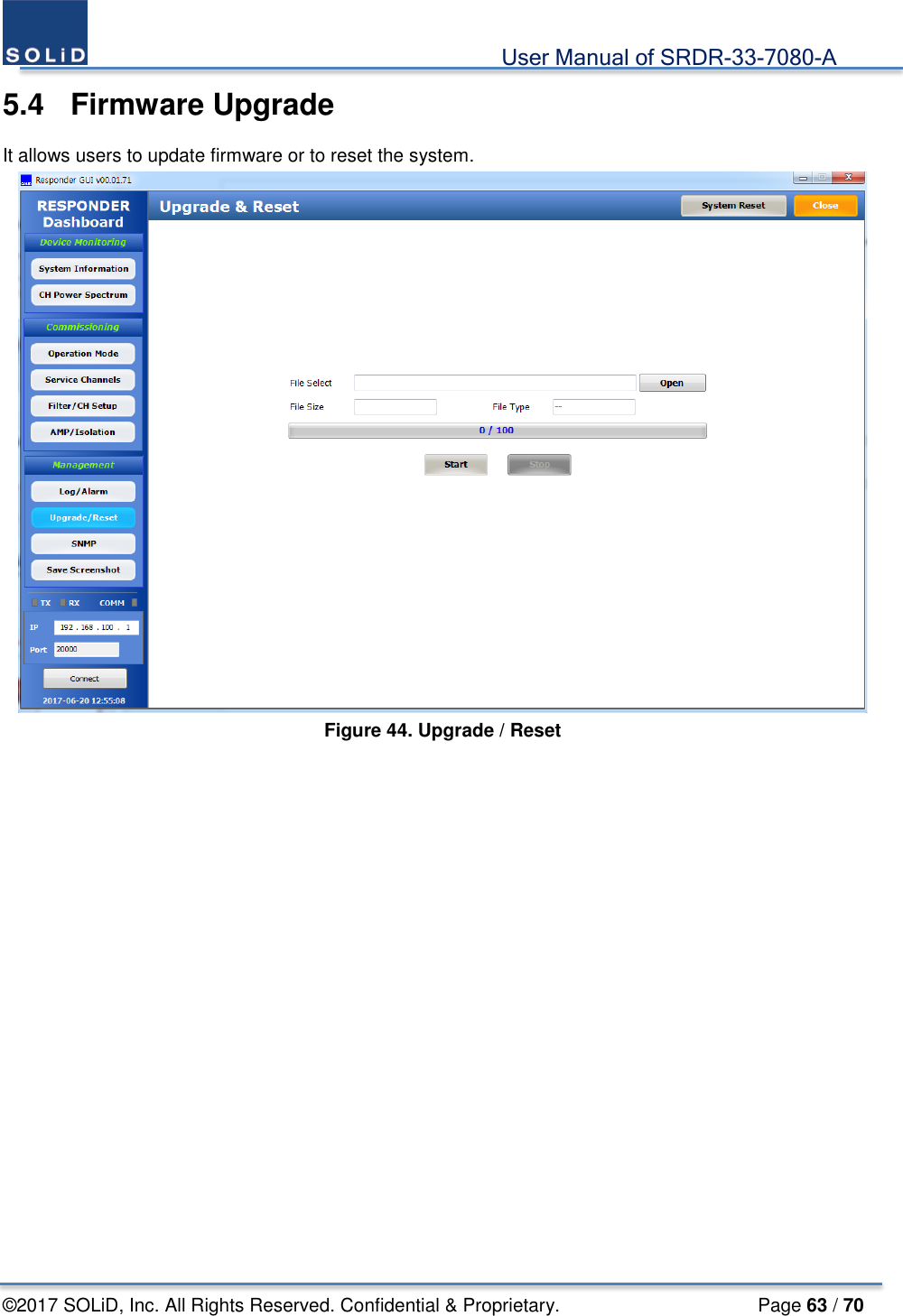
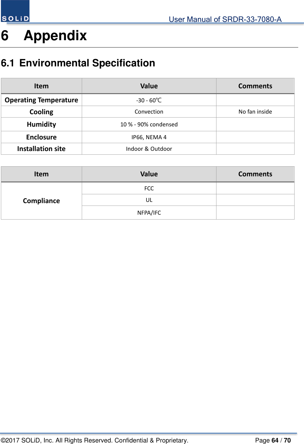
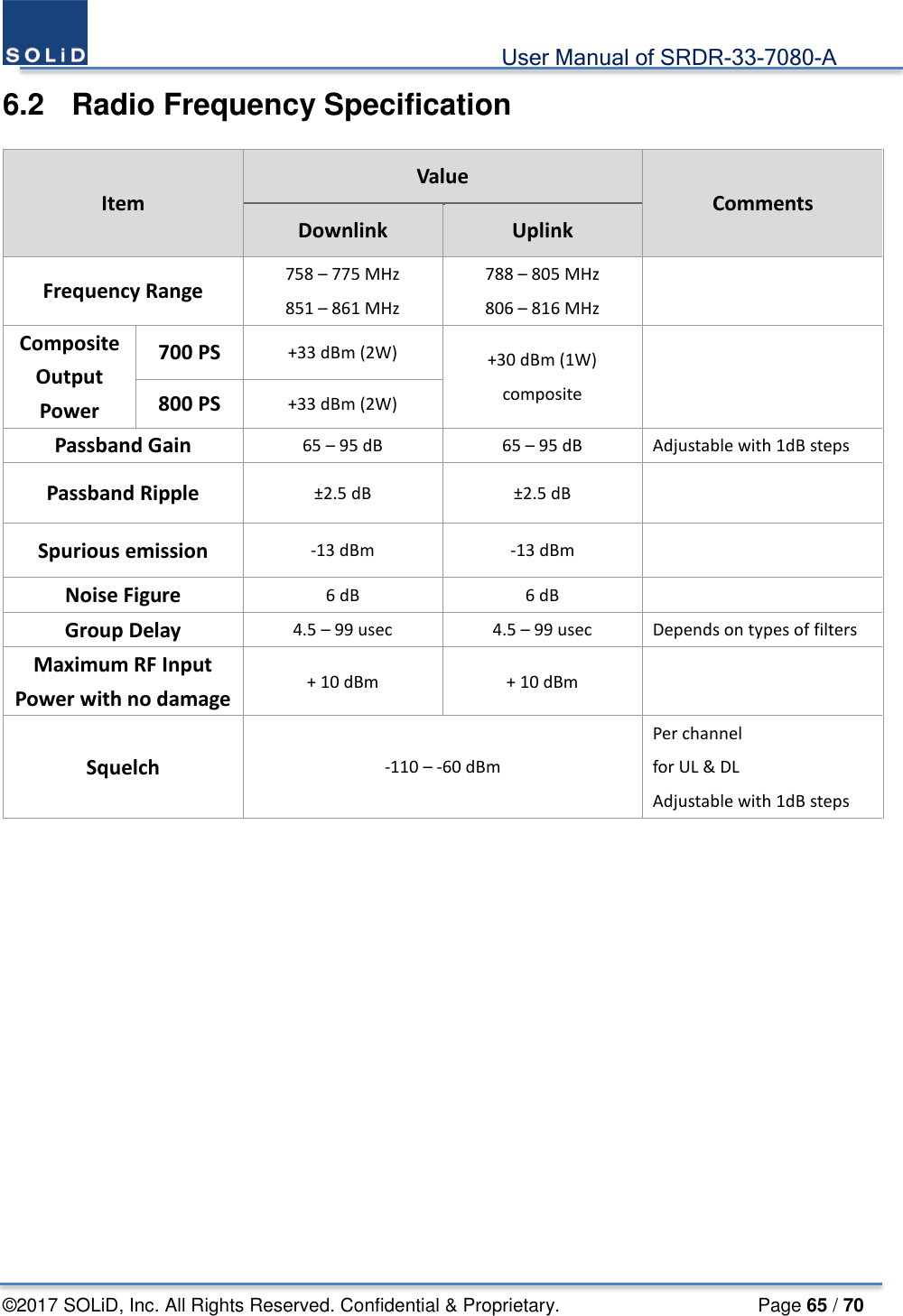
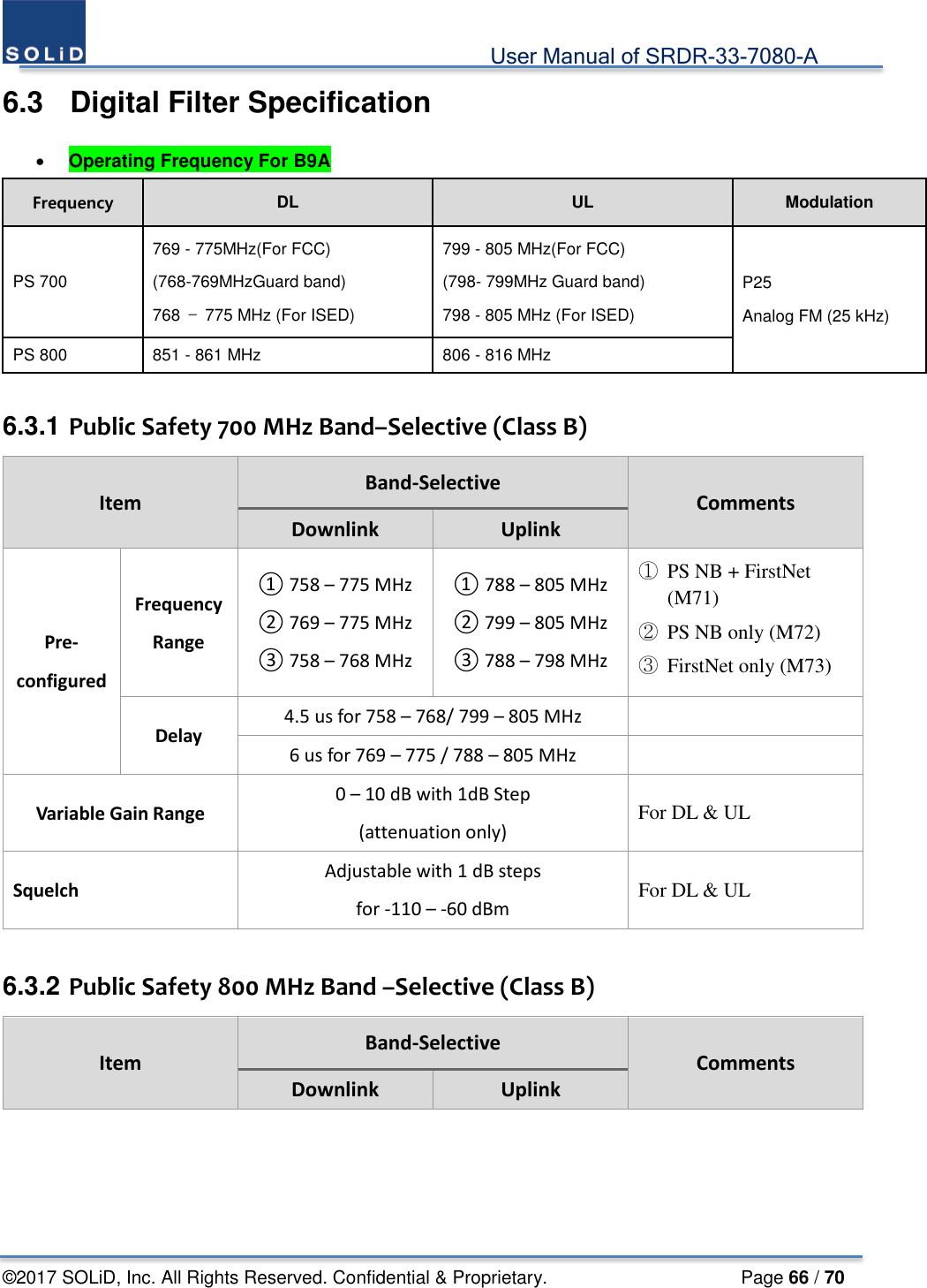
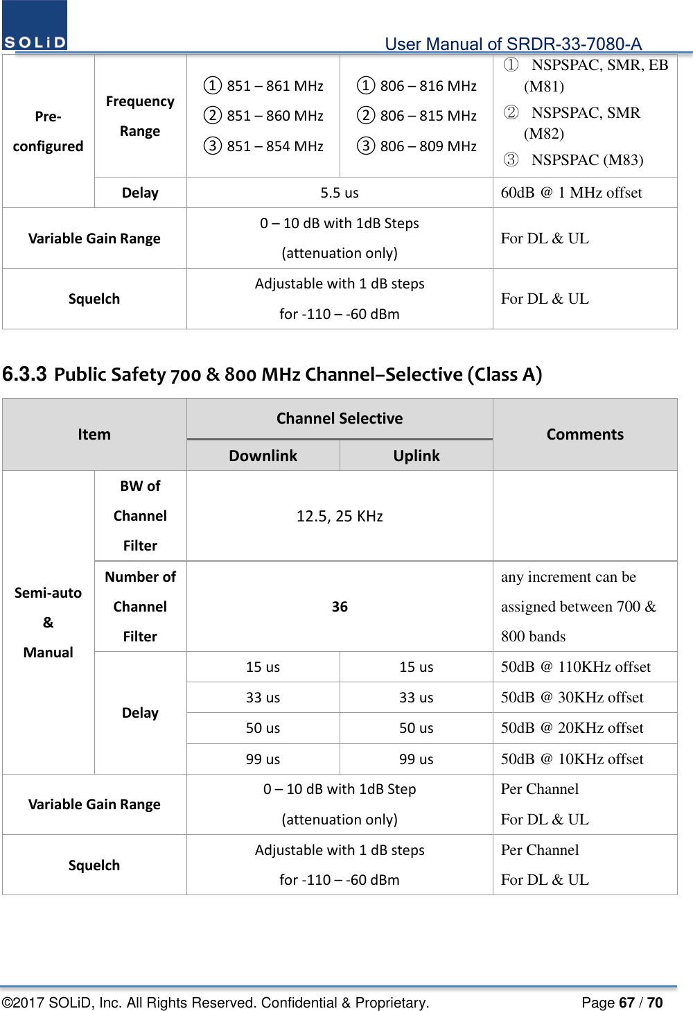
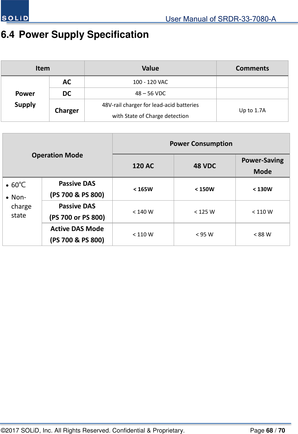
![User Manual of SRDR-33-7080-A ©2017 SOLiD, Inc. All Rights Reserved. Confidential & Proprietary. Page 16 / 70 1.4 Antenna Installation Notices 1.4.1 Antenna Requirements The installation procedure must result in the signal booster complying with FCC requirements 90.219(d). In order to meet FCC requirements 90.219(d), it may be necessary for the installer to reduce the UL and/or DL output power for certain installations. FCC regulation mandate that the ERP of type B signal boosters should not exceed 5W. Use of unauthorized antennas, cables, and/or coupling devices not conforming with ERP/EIRP and/or indoor-only restrictions is prohibited. Only 50 ohm rated antennas, cables and passive equipment shall be used with this equipment. Any device attached to this equipment not meeting this standard may cause degradation and unwanted signals in the bi-directional system. All components connected to this device must operate in the frequency range of this device. 1.4.2 Donor Antenna Requirements Maximum Service Antenna Gain is calculated by the below formula. [ERP] – [nominal output power] – [cable Loss] Yagi or silmilar type: Directional antenna with a sharp beam, at maximum 17 dBi At minimum cable loss is 5 dB Example of the available antenna specification EIRP = 27 dBm (UL output power) - 5 dB (Cable Loss) + 17 dBi (Antenna gain) = 39 dBm ERP = EIRP – 2.15 dB = 39 – 2.15 = 36.85 dBm < 37 dBm (FCC limit) 1.4.3 Service Antenna Requirements Maximum Service Antenna Gain is calculated by the below formula. [ERP] – [nominal output power] – [cable Loss] – [allocated power] Omni antenna with 0 – 2 dBi gain, Patch antenna with wide beam of 10 dBi gain, At maximum 17 dBi At mimimum 5 antennas and splitters At minimum cable loss is 10 dB Example of the available antenna specification EIRP = 33 dBm (DL output power) - 7 dB (Splitter Loss) – 5 dB (Cable loss) + 17dBi (Antenna gain) = 38 dBm ERP = EIRP – 2.15 dB = 38 – 2.15 = 35.85 dBm < 37 dBm (FCC limit)](https://usermanual.wiki/SOLiD/SRDR7080A/User-Guide-3535691-Page-16.png)