Class A_SOLiD Responder_User Manual_Rev.1
User Manual of SRDR-33-7080-A
©2017 SOLiD, Inc. All Rights Reserved. Confidential & Proprietary. Page 1 / 70
SOLiD Responder
Public Safety 700/800 MHz Digital Repeater
SRDR-33-7080-A
User Manual
Version 1.0
8/8/2017

User Manual of SRDR-33-7080-A
©2017 SOLiD, Inc. All Rights Reserved. Confidential & Proprietary. Page 2 / 70
Preface
The user documentation set of SOLiD Responder consists of following main statements:
• SOLiD Responder SRDR-33-7080-A-FN User Manual: Precautions and instructions for installing and setting
up SRDR-33-7080-A-FN.
Copyright
All rights are reserved ©2017 SOLiD. Confidential and proprietary. Information contained in this document is
company private to SOLiD and should not be modified, used, copied, reproduced or disclosed in whole or in part
without the written consent of SOLiD.
Trademark Information
No right, license, or interest to SOLiD Responder trademarks is granted here. By using this document, you agree not
to assert any right, license, or interest with respect to such trademark. Other product names mentioned in this
manual are used for identification purposes only and may be trademarks or registered trademarks of their respective
companies.
Disclaimer of Liability
The contents of this document, including graphics and screenshots, are current as of the date of publication. SOLiD
reserves the right to change the contents without prior notice. In no event shall SOLiD be liable for any damages
resulting from loss of data, loss of use or loss of profits. SOLiD further disclaims any and all liability for indirect,
incidental, special, consequential or other similar damages. This disclaimer of liability applies to all products,
publications and services during and after the warranty period.
Getting Support and Providing Feedback
To authorize technical support or to establish a return authorization for defective units, make sure you have the
SOLiD serial numbers available. Serial numbers are located on the bottom of the product, as well as on the box in
which it was delivered. Contact SOLiD for additional support information:
User Manual of SRDR-33-7080-A
©2017 SOLiD, Inc. All Rights Reserved. Confidential & Proprietary. Page 3 / 70
Contact Information
SOLiD Gear, Inc. Headquarters
Address: 800 Klein Road, Suite 200, Plano, TX 75074
Phone: 888.409.9997
Email for support issues: support@solid.com
Web site: www.solid.com
Revision History
Revision
Number Issue Date Changes
1.0 Aug 8th, 2017 Initial Release

User Manual of SRDR-33-7080-A
©2017 SOLiD, Inc. All Rights Reserved. Confidential & Proprietary. Page 4 / 70
Contents
1 General Information .............................................................................................. 10
1.1 Safety Notices ............................................................................................................................. 10
1.2 FCC Notices ................................................................................................................................ 12
1.3 Industry Canada(IC) Notices ....................................................................................................... 14
1.4 Antenna Installation Notices ........................................................................................................ 16
1.4.1 Antenna Requirements .................................................................................................. 16
1.4.2 Donor Antenna Requirements ....................................................................................... 16
1.4.3 Service Antenna Requirements ..................................................................................... 16
2 Product Overview .................................................................................................. 17
2.1 Introduction .................................................................................................................................. 17
2.2 Main Features ............................................................................................................................. 17
2.3 Ordering Information ................................................................................................................... 18
2.4 Signal Flow .................................................................................................................................. 19
2.5 Description of Modules ................................................................................................................ 20
2.5.1 Integrated PSU .............................................................................................................. 20
2.5.2 Power Amplifier Unit (PAU) ........................................................................................... 20
2.5.3 Digital Unit (DU) ............................................................................................................. 20
2.5.4 Radio Frequency Unit (RFU) ......................................................................................... 20
2.5.5 CPU ............................................................................................................................... 20
2.5.6 Multiplexer ...................................................................................................................... 21
2.5.7 Signal Analysis Module (SAM) ...................................................................................... 21
2.6 External Interface ........................................................................................................................ 22
2.7 Operation ..................................................................................................................................... 23
2.7.1 Classes and Passbands Types ..................................................................................... 23
2.7.2 Procedure to Choose Passband .................................................................................... 26
2.7.3 Automatic Shutdown of Amplifiers ................................................................................. 30
3 Installing the SOLiD RESPONDER ....................................................................... 32
3.1 Overview of the Installation Procedure ....................................................................................... 32
3.2 Location Installation Site ............................................................................................................. 33
3.2.1 Product Dimension ........................................................................................................ 33
3.2.2 Installation Environment ................................................................................................ 34
3.3 Unpacking and Package Contents .............................................................................................. 34

User Manual of SRDR-33-7080-A
©2017 SOLiD, Inc. All Rights Reserved. Confidential & Proprietary. Page 5 / 70
3.4 Mounting the Product .................................................................................................................. 35
3.4.1 Mounting Method ........................................................................................................... 35
3.4.2 Installation the Wall Mount Bracket ............................................................................... 36
3.4.3 Rack Mount Installation ................................................................................................. 36
3.5 Grounding .................................................................................................................................... 36
3.6 Antenna Connections and Guidelines ......................................................................................... 38
3.6.1 Donor Antenna Installation Guidelines .......................................................................... 38
3.6.2 Indoor Antenna Installation Guidelines .......................................................................... 38
3.6.3 RF Cable Installation Guidelines ................................................................................... 38
3.6.4 Connecting Antennas .................................................................................................... 38
3.7 Connecting Power Cables and Power-up ................................................................................... 39
3.7.1 Integrated PSU .............................................................................................................. 39
3.7.2 Power Redundancy ....................................................................................................... 39
3.7.3 AC Power Cabling ......................................................................................................... 40
3.7.4 DC Power Cabling ......................................................................................................... 41
3.7.5 Power Up ....................................................................................................................... 41
3.8 Connecting NFPA Alarms ........................................................................................................... 42
3.8.1 Choose the alarms to be monitored .............................................................................. 42
3.8.2 Select the type of external alarms ................................................................................. 42
3.8.3 Connect cable to the alarm box ..................................................................................... 43
3.8.4 Verify the state of connection ........................................................................................ 43
4 Setup and Commissioning ................................................................................... 44
4.1 Overview of the Commissioning Procedure ................................................................................ 44
4.2 Connecting the GUI to the Product ............................................................................................. 45
4.2.1 Network Information of GUI ........................................................................................... 45
4.2.2 Log in GUI ...................................................................................................................... 46
4.2.3 GUI Main Screen ........................................................................................................... 46
4.3 Configuring Operation Mode of the Product ............................................................................... 48
4.3.1 Operation Mode Window ............................................................................................... 48
4.3.2 Changing Operation Mode ............................................................................................. 49
4.3.3 Filter Mode ..................................................................................................................... 49
4.3.4 Echo Cancellation .......................................................................................................... 49
4.3.5 Power Supply Configuration .......................................................................................... 49
4.3.6 AMP Shutdown function ................................................................................................ 50
4.3.7 Summary ........................................................................................................................ 50

User Manual of SRDR-33-7080-A
©2017 SOLiD, Inc. All Rights Reserved. Confidential & Proprietary. Page 6 / 70
4.4 Setup Channel Configuration & RF parameters ......................................................................... 51
4.4.1 Input the information of service channels ...................................................................... 51
4.4.2 Setup Parameters of Digital Filter .................................................................................. 51
4.4.2.1 Pre-Configured Filter Mode ............................................................................................... 51
4.4.2.2 36 Channelized Filters ....................................................................................................... 53
4.5 Isolation Measurement & Tune-up .............................................................................................. 55
4.5.1 Monitor Downlink Input Power ....................................................................................... 55
4.5.2 Measure the isolation between donor antenna and service antenna ............................ 55
4.5.3 Evaluate isolation value & reconfigure the antenna installation .................................... 55
4.5.4 Test coverage area ........................................................................................................ 56
4.5.5 Verify UL gain and Performs test calls .......................................................................... 56
4.6 SNMP traps & Time Settings ...................................................................................................... 57
5 Administrations ..................................................................................................... 58
5.1 Viewing General Information ....................................................................................................... 58
5.2 Alarm Remedy ............................................................................................................................. 59
5.3 Alarm Log .................................................................................................................................... 61
5.3.1 Alarm History ................................................................................................................. 61
5.3.2 Alarm Mask / Shutdown ................................................................................................. 62
5.4 Firmware Upgrade....................................................................................................................... 63
6 Appendix ................................................................................................................ 64
6.1 Environmental Specification ........................................................................................................ 64
6.2 Radio Frequency Specification ................................................................................................... 65
6.3 Digital Filter Specification ............................................................................................................ 66
6.3.1 Public Safety 700 MHz Band–Selective (Class B) ........................................................ 66
6.3.2 Public Safety 800 MHz Band –Selective (Class B) ....................................................... 66
6.3.3 Public Safety 700 & 800 MHz Channel–Selective (Class A) ......................................... 67
6.4 Power Supply Specification ......................................................................................................... 68
6.5 Mechanical Specification ............................................................................................................. 69

User Manual of SRDR-33-7080-A
©2017 SOLiD, Inc. All Rights Reserved. Confidential & Proprietary. Page 7 / 70
List of Figures
Figure 1. FCC Part 90 Class Information in the GUI .................................................................................. 12
Figure 2. Signal Flow of SRDR-33-7080-A-FN ........................................................................................... 19
Figure 3. Inner View of the SRDR-33-7080-A-FN ...................................................................................... 20
Figure 4. External Connectors .................................................................................................................... 22
Figure 5. The Spectrum of M701 ................................................................................................................ 24
Figure 6. The Spectrum of M702 ................................................................................................................ 24
Figure 7. The Spectrum of M703 ................................................................................................................ 24
Figure 8. The Spectrum of M801 ................................................................................................................ 24
Figure 9. The Spectrum of M802 ................................................................................................................ 25
Figure 10. The Spectrum of M803 .............................................................................................................. 25
Figure 11. The Spectrum of M036 excluding FirstNet ................................................................................ 25
Figure 12, The Spectrum of M036 including FirstNet ................................................................................. 25
Figure 13. 3 times Failure in Shutdown Algorithm Type 1 .......................................................................... 30
Figure 14. 2 times Failure in Shutdown Algorithm Type 1 .......................................................................... 30
Figure 15. Shutdown Algorithm Type 2 ....................................................................................................... 31
Figure 16. Dimensions of SRDR-7080-A-FN .............................................................................................. 33
Figure 17. Mount Bracket for Wall and Rack .............................................................................................. 35
Figure 18. Dimensions used to install Product on the Wall ........................................................................ 35
Figure 19. The Location of Ground Lug ...................................................................................................... 37
Figure 20. Information of Terminal .............................................................................................................. 37
Figure 21. Connection for AC-UPS site ...................................................................................................... 39
Figure 22. Connection for DC-UPS site ...................................................................................................... 39
Figure 23. Connections with AC & Batteries ............................................................................................... 40
Figure 24. AC Cable Drawing ..................................................................................................................... 40
Figure 25. DC Cable Drawing ..................................................................................................................... 41
Figure 26. Relay Output Cable Drawing ..................................................................................................... 43
Figure 27. External Alarm Emulator ............................................................................................................ 43
Figure 28. GUI Port of SOLiD Responder ................................................................................................... 45
Figure 29. Login Window ............................................................................................................................ 46

User Manual of SRDR-33-7080-A
©2017 SOLiD, Inc. All Rights Reserved. Confidential & Proprietary. Page 8 / 70
Figure 30. Main Screen of GUI ................................................................................................................... 46
Figure 31. System Operation Mode Window .............................................................................................. 48
Figure 32. Power Supply Configuration ...................................................................................................... 49
Figure 33. AMP Shutdown Function ........................................................................................................... 50
Figure 34. Summary of Selecting the Operation Modes ............................................................................. 50
Figure 35. Service Channels Window ......................................................................................................... 51
Figure 36. Pre-Configured Filter Mode Window.......................................................................................... 52
Figure 37. Channelized Filter Mode Window .............................................................................................. 53
Figure 38. Isolation Measurement Window ................................................................................................. 55
Figure 39. SNMP Configuration .................................................................................................................. 57
Figure 40. System Information Window ...................................................................................................... 58
Figure 41. Example of Alarm Remedy ........................................................................................................ 60
Figure 42. System Log ................................................................................................................................ 61
Figure 43. Alarm Mask / Shutdown ............................................................................................................. 62
Figure 44. Upgrade / Reset ......................................................................................................................... 63

User Manual of SRDR-33-7080-A
©2017 SOLiD, Inc. All Rights Reserved. Confidential & Proprietary. Page 9 / 70
List of Tables
Table 1. License Descriptions ..................................................................................................................... 18
Table 2. Unit Functions ............................................................................................................................... 21
Table 3. Passbands of Class A Device ....................................................................................................... 23
Table 4. Passbands of Class B Device ....................................................................................................... 23
Table 5. Passband Types ........................................................................................................................... 23
Table 6. Mechanical Specification .............................................................................................................. 33
Table 7. Packing List of the SRDR-33-7080-A-FN ..................................................................................... 34
Table 8. Power Supply Specification .......................................................................................................... 39
Table 9. AC Port Pin Description ................................................................................................................ 40
Table 10. DC Port Pin Description .............................................................................................................. 41
Table 11. NFPA Alarm Connection upon the Power Supply configuration ................................................. 42
Table 12. IP address of SOLiD Responder ................................................................................................. 45
Table 13. Access Information to AP ............................................................................................................ 45
Table 14. Description of Main Menu ........................................................................................................... 47
Table 15. Description of Operation Mode Items ......................................................................................... 48
Table 16. Pre-configured Filter Parameters ................................................................................................ 52
Table 17. 36 Channelized Filter Parameters .............................................................................................. 53
Table 18. Parameters of Time Setting ........................................................................................................ 57
Table 19. Description of System Information .............................................................................................. 58
Table 20. Description of Alarms .................................................................................................................. 59
Table 21. Description of Terms in the Alarm Mask ..................................................................................... 62
User Manual of SRDR-33-7080-A
©2017 SOLiD, Inc. All Rights Reserved. Confidential & Proprietary. Page 10 / 70
1 General Information
1.1 Safety Notices
“Only qualified personnel should handle the equipment. Any person involved in installation
or service of the equipment should understand and follow these safety guidelines.”
General Caution
SOLiD assumes no liability for the customer’s or user’s failure to comply with these requirements:
• Explosive atmospheres - To avoid explosion or fire, do not operate this equipment in the presence of
flammable gases or fumes.
• Lightning danger - Do not install or make adjustments to this equipment during an electrical storm.
Do not operate this unit on or close to flammable materials, as the unit may reach high temperatures due
to power dissipation.
Do not use any solvents, chemicals, or cleaning solutions containing alcohol, ammonia, or abrasives on the
equipment.
When working with equipment outdoors, make sure to fasten the door or cover securely in an open state
to prevent the door from slamming shut by the wind.
Use this eqipment only for the purpose specified by the manufacturer. Do not carry out any modifications
or fit any spare parts which are not sold or recommended by the manufacturer. This could cause fires,
electric shock or other injuries.
Any local regulations are to be followed when operating repeaters.
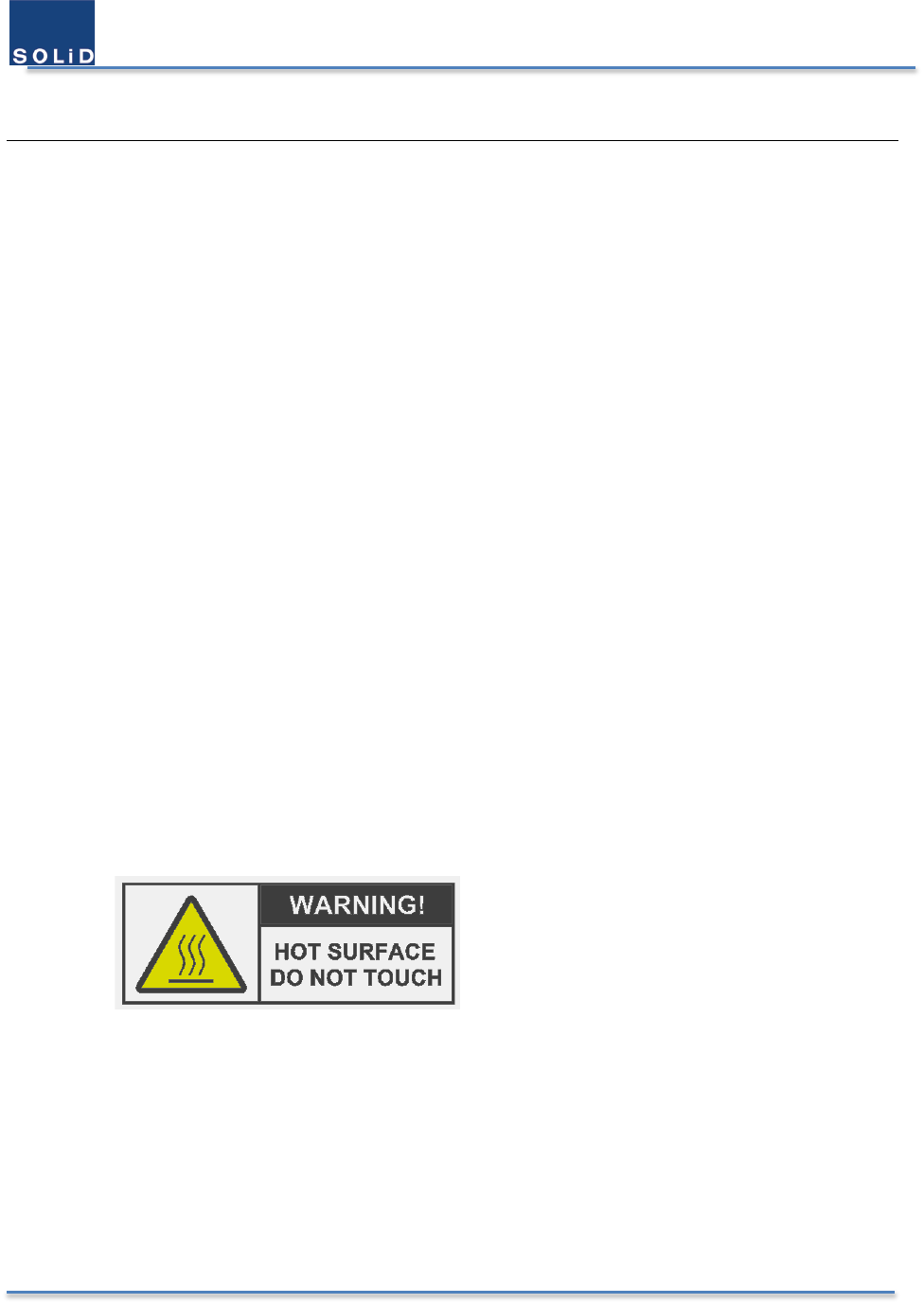
Hot Burn Injury
Due to the power dissipation, the equipment may reach a very high temperature.
Be careful not to touch the heat-sink part or the hot parts inside and outside.
Since the temperature goes lower slowly, pay caution after putting off the equipment.
Power Supply Precaution
In case of connection to the sealed lead-acid batteries, this equiment is intended for installation in
restricted access areas. A restricted access area is an area to which access can be gained only by service
personnel through the use of a special tool, lock and key, or other means of security, and which is
controlled by the authority responsible for the location.

User Manual of SRDR-33-7080-A
©2017 SOLiD, Inc. All Rights Reserved. Confidential & Proprietary. Page 11 / 70
Only service personnel or skilled person should handle the connection procedure between the product
and the batteries including auxillary accessories concerning the power supply sources.
This power of this system should be supplied with the wiring installed in a normal building.
If powered directly from the mains distribution system, it shall be used additional protection, such as
overvoltage protection device
Grounding
Signal Booster, feeders, donor antenna, service antenna and auxiliary equipment (splitters, tabs, .etc) are
required to be bonded to protective grounding using the bonding stud or screw provided with each unit.
Dangerous Electric Shock
Obey all general and regional installation and safety regulations relating to work on high voltage
installations, as well as regulations covering correct use of tools and personal protective equipment.
The power supply unit in repeaters contains dangerous voltage level, which can cause electric shock.
Switch the main power supply off prior to any work in such a repeater.
Electrostatic Discharge
Static electricity means no risk of personal injury but it can severely damage essential parts of the Signal
Parts on the printed circuit boards as well as other parts in the Signal Booster are sensitive to electrostatic
discharge.
Never touch printed circuit boards or uninsulated conductor surfaces unless absolutely necessary.
If you must handle printed circuit boards or uninsulated conductor surfaces, use ESD protective equipment,
or first touch the Signal Booster chassis with your hand and then do not move your feet on the floor.
Never let your clothes touch printed circuit boards or uninsulated conductor surfaces.
Disposal of Electric and Electronic Waste
Pursuant to the WEEE EU Directive electronic and electrical waste must not be disposed of with unsorted
waste. Please contact your local recycling authority for disposal of this product.
Dispose of used batteries according to the instructions in accordance with legal laws.
User Manual of SRDR-33-7080-A
©2017 SOLiD, Inc. All Rights Reserved. Confidential & Proprietary. Page 12 / 70
1.2 FCC Notices
FCC Part 90 statement
This equipment complies with Title 47 CFR Parts 90.
This is a 90.219 Class A device.
Home/personal use are prohibited.
The installation procedure must result in the signal booster complying with FCC/ISED requirements 90.219(d)/
RSS-131 Sec.6.3 & 6.4. In order to meet FCC/ ISED requirements, it may be necessary for the installer to reduce
the UL and/or DL output power for certain installations.
Use of unauthorized antennas, cables, and/or coupling devices not conforming with ERP/EIRP and/or indoor-
only restrictions is prohibited.
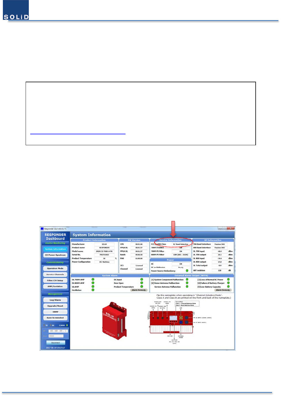
If all the passbands are no wider than 75 KHz, the equipment will be Class A device. Otherwise it is Class B device.
User can also check FCC part 90 Class from the System Information window.
Figure 1. FCC Part 90 Class Information in the GUI
If you are unsure, contact your provider.
WARNING: This is a 90.219 Class A device.
This is NOT a CONSUMER device. It is designed for installation by FCC LICENSEES and QUALIFIED
INSTALLERS. You MUST have an FCC LICENSE or express consent of an FCC Licensee to operate
this device. You MUST register Class B signal boosters (as defined in 47 CFR 90.219) online at
www.fcc.gov/signalboosters/registration. Unauthorized use may result in significant forfeiture
penalties, including penalties in excess of $100,000 for each continuing violation.

User Manual of SRDR-33-7080-A
©2017 SOLiD, Inc. All Rights Reserved. Confidential & Proprietary. Page 13 / 70
FCC Part 15 statement
This device complies with Part 15 of the FCC Rules. Operation is subject to the following two conditions: (1) this
device may notcause harmful interference, and (2) this device must accept any interference received, including
interference that may cause undesired operation.
Changes or modifications not expressly approved by the party responsible for compliance could “void” the
user's authority to operate this equipment.
This equipment has been tested and found to comply with the limits for a Class A digital device, pursuant to
part 15 of the FCC Rules. These limits are designed to provide reasonable protection against harmful
interference when the equipment is operated in a commercial environment. This equipment generates, uses,
and can radiate radio frequency energy and, if not installed and used in accordance with the instruction manual,
may cause harmful interference to radio communications. Operation of this equipment in a residential area is
likely to cause harmful interference in which case the user will be required to correct the interference at his
own expense.
Radiofrequncy Radiation Exposure Limits
This equipment complies with FCC radiation exposure limits set forth for an uncontrolled environment. In order to
avoid the possibility of exceeding the FCC radio frequency exposure limits, human proximity to the antenna shall not
be less than 200cm during normal operation. This device must not be co-located or operating in conjunction with
any other antenna or transmitter.

User Manual of SRDR-33-7080-A
©2017 SOLiD, Inc. All Rights Reserved. Confidential & Proprietary. Page 14 / 70
1.3 Industry Canada(IC) Notices
This device complies with Industry Canada license-exempt RSS standard(s). Operation is subject to the following two
conditions: (1) this device may not cause interference, and (2) this device must accept any interference, including
interference that may cause undesired operation of the device.
Le présent appareil est conforme aux CNR d’Industrie Canada applicables aux appareils radio exempts de licence.
Son exploitation est autorisée aux deux conditions suivantes: (1) .il ne doit pas produire de brouillage; et (2) il doit
accepter tout brouillage radioélectrique subi, même si celui-ci est susceptible d’en compromettre le fonctionnement.
RSS-GEN, Sec. 7.1.2 – (transmitters)
Under Industry Canada regulations, this radio transmitter may only operate using an antenna of a type and maximum
(or lesser) gain approved for the transmitter by Industry Canada. To reduce potential radio interference to other
users, the antenna type and its gain should be chosen so that the equivalent isotropically radiated power (e.i.r.p.) is
not more than that necessary for successful communication.
Conformément à la réglementation d’Industrie Canada, le présent émetteur radio peut fonctionneravec une antenne
d’un type et d’un gain maximal (ou inférieur) approuvé pour l’émetteur par Industrie Canada. Dans le but de réduire
les risques de brouillage radioélectrique à l’intention desautres utilisateurs, il faut choisir le type d’antenne et son
gain de sorte que la puissance isotroperayonnée quivalente (p.i.r.e.) ne dépassepas l’intensité nécessaire à
l’établissement d’une communication satisfaisante.
RSS-GEN, Sec. 7.1.2 – (detachable antennas)
This radio transmitter (identify the device by certification number, or model number if Category II)has been approved
by Industry Canada to operate with the antenna types listed below with the maximum permissible gain and required
antenna impedance for each antenna type indicated. Antenna types not included in this list, having a gain greater
than the maximum gain indicated for that type, are strictly prohibited for use with this device.
Le présent émetteur radio (identifier le dispositif par son numéro de certification ou son numéro de modèle s’il fait
partie du matériel de catégorie I) a été approuvé par Industrie Canada pour fonctionner avec les types d’antenne
énumérés ci-dessous et ayant un gain admissible maximal et l’impédance requise pour chaque type d’antenne. Les
types d’antenne non inclus dans cette liste,ou dont le gain est supérieur au gain maximal indiqué, sont strictement
interdits pour l’exploitation de l’émetteur.
RSS-102 RF Exposure
This equipment complies with RF radiation exposure limits set forth for an uncontrolled environment. This
equipment should be installed and operated with a minimum distance of 200 cm between the radiator and your

User Manual of SRDR-33-7080-A
©2017 SOLiD, Inc. All Rights Reserved. Confidential & Proprietary. Page 15 / 70
body. This transmitter must not be co-located or operating in conjunction with any other antenna or transmitter. RF
exposure will be addressed at time of installation and the use of higher gain antennas may require larger separation
distances.
L’antenne (ou les antennes) doit être installée de façon à maintenir à tout instant une distance
minimum de au moins 200 cm entre la source de radiation (l’antenne) et toute personne physique. Cet appareil ne
doit pas être installé ou utilisé en conjonction avec une autre antenne ou émetteur.
RSS-131 Section 5.3
The Manufacturer's rated output power of this equipment is for single carrier operation. For situations when
multiple carrier signals are present, the rating would have to be reduced by 3.5 dB, especially where the output
signal is re-radiated and can cause interference to adjacent band users. This power reduction is to be by means of
input power or gain reduction and not by an attenuator at the output of the device.
a. The nominal passband gain (dB): 95dB maximum
b. The nominal bandwidth: 12.5KHz – 10MHz
c. The rated mean output power: 33 dBm per each band maximum
The input and output impedances: 50 ohm, 50 ohm

User Manual of SRDR-33-7080-A
©2017 SOLiD, Inc. All Rights Reserved. Confidential & Proprietary. Page 16 / 70
1.4 Antenna Installation Notices
1.4.1 Antenna Requirements
The installation procedure must result in the signal booster complying with FCC requirements 90.219(d). In order to
meet FCC requirements 90.219(d), it may be necessary for the installer to reduce the UL and/or DL output power for
certain installations. FCC regulation mandate that the ERP of type B signal boosters should not exceed 5W.
Use of unauthorized antennas, cables, and/or coupling devices not conforming with ERP/EIRP and/or indoor-only
restrictions is prohibited. Only 50 ohm rated antennas, cables and passive equipment shall be used with this
equipment. Any device attached to this equipment not meeting this standard may cause degradation and unwanted
signals in the bi-directional system. All components connected to this device must operate in the frequency range
of this device.
1.4.2 Donor Antenna Requirements
Maximum Service Antenna Gain is calculated by the below formula.
[ERP] – [nominal output power] – [cable Loss]
Yagi or silmilar type: Directional antenna with a sharp beam, at maximum 17 dBi
At minimum cable loss is 5 dB
Example of the available antenna specification
EIRP = 27 dBm (UL output power) - 5 dB (Cable Loss) + 17 dBi (Antenna gain) = 39 dBm
ERP = EIRP – 2.15 dB = 39 – 2.15 = 36.85 dBm < 37 dBm (FCC limit)
1.4.3 Service Antenna Requirements
Maximum Service Antenna Gain is calculated by the below formula.
[ERP] – [nominal output power] – [cable Loss] – [allocated power]
Omni antenna with 0 – 2 dBi gain, Patch antenna with wide beam of 10 dBi gain, At maximum 17 dBi
At mimimum 5 antennas and splitters
At minimum cable loss is 10 dB
Example of the available antenna specification
EIRP = 33 dBm (DL output power) - 7 dB (Splitter Loss) – 5 dB (Cable loss) + 17dBi (Antenna gain) = 38
dBm
ERP = EIRP – 2.15 dB = 38 – 2.15 = 35.85 dBm < 37 dBm (FCC limit)

User Manual of SRDR-33-7080-A
©2017 SOLiD, Inc. All Rights Reserved. Confidential & Proprietary. Page 17 / 70
2 Product Overview
2.1 Introduction
SRDR-33-7080-A-FN is an excellent product from SOLiD, which is the signal booster to support public safety radio
services typically indoors. It was designed to give great benefits to agents such as First Responder, fire fighters to
communicate each other under the emergency as well as a normal situation. And it provides customers the effective
solution from the point of total cost of ownership, survivability, flexibility to the circumstance, and easy installation.
SRDR-33-7080-A-FN is a dual band digital repeater to choose the various digital filters with several delays and several
rejections. It features 36 FPGA-based, software-controlled, and user-selectable filters across 700 & 800 MHz bands.
It can help you configure the best operation to eliminate the adjacent interference and to mitigate the Time
Difference Interference (TDI) problem. So, it can be configured as FCC part 90. Class A device or FCC part 90. Class B
device. User should follow instructions which are described in 1. 2 FCC notices in case of class B device.
2.2 Main Features
NFPA/IFC Compliant
Dual-Band 700/800 MHz & 2W per Band
FirstNet Support
Channel-Selective & Band-Selective by user-selectable software
Integrated Battery Charger and Alarming
Operation at 60°C and Extended Life
Simple and Low-powered Active DAS interface
User Manual of SRDR-33-7080-A
©2017 SOLiD, Inc. All Rights Reserved. Confidential & Proprietary. Page 18 / 70
2.3 Ordering Information
Table 1. License Descriptions
SRDR-33-7080-A-FN Digital Repeater, 2 Watt, 700/800 MHz Public Safety + FirstNet, Band selective,
NEMA4, NFPA/IFC Compliant.
SRDR-33-L1 Digital Repeater Channel Selective License Upgrade
SRDR-33-L2
Digital Repeater Echo Cancellation License Upgrade
SRDR-33-L3 Digital Repeater System Analysis Module License Upgrade, includes plugin module
The SOLiD RESPONDER is available from the factory in four different configurations. The base configuration defaults
to a “Band Selective” device and does not include the Echo Cancellation or System Analysis features. The base
configuration can be factory upgraded by purchasing any, or all, of the three additional licensable software
configurations. Refer to the following descriptions or consult your local SOLiD Sales Engineer for guidance in selecting
the best product configuration for your application.
SRDR-33-7080-A-FN (Base Configuration)
This Part Number represents the base configuration, which includes the Band Selective mode only (FCC Class B
Wideband Signal Booster Device). All Class B Signal Booster devices must be registered with the FCC prior to
operation.
SRDR-33-L1 (Channel Selective Software Upgrade)
This license upgrade adds a Channel Selective mode allowing the user to switch between Band Selective and Channel
Selective operation. When operating at channel bandwidths of 75KHz or less, this device is classified by FCC as a
Class A Narrowband Signal Booster Device, and as such, does not require registration with the FCC. Channel Selective
mode is typically used in RF congested areas where narrow pass windows are needed to minimize interference from
undesired frequencies. In Channel Selective mode, also known as “Channelized” mode, the user can assign up to 36
window filters, in any increment, between the 700 and 800 MHz bands.
SRDR-33-L2 (Echo Cancellation Software Upgrade)
Echo Cancellation Mode (“ZeroDelta” feature). This license upgrade adds an Echo Cancellation feature to Band and
Channel Selective modes. The Echo Cancellation feature includes an advanced patented algorithm that allows the
repeater to maintain maximum gain even when system isolation deteriorates to as low as the gain of the repeater.
Traditional repeaters require at least 15-20dB more isolation than system gain to prevent oscillation. The “ZeroDelta”
feature allows normal operation with 0dB difference between system isolation and system gain. This feature has
many advantages such as increased system stability and reliability, easy system commissioning and optimization,
and increased coverage footprint and cost savings in applications where weak off-air signals require a high gain
setting.
SRDR-33-L3 (System Analysis Module – Hardware and Software Upgrade)
System Analysis Module (SAM). This part number includes a hardware plug-in module and software that enables
advanced system analysis, such as: data logging of wideband spectrum to aid in application of window filters, to
spectrum analyzer features that display near-real time spectrum readings for both input and output.
User Manual of SRDR-33-7080-A
©2017 SOLiD, Inc. All Rights Reserved. Confidential & Proprietary. Page 19 / 70
2.4 Signal Flow
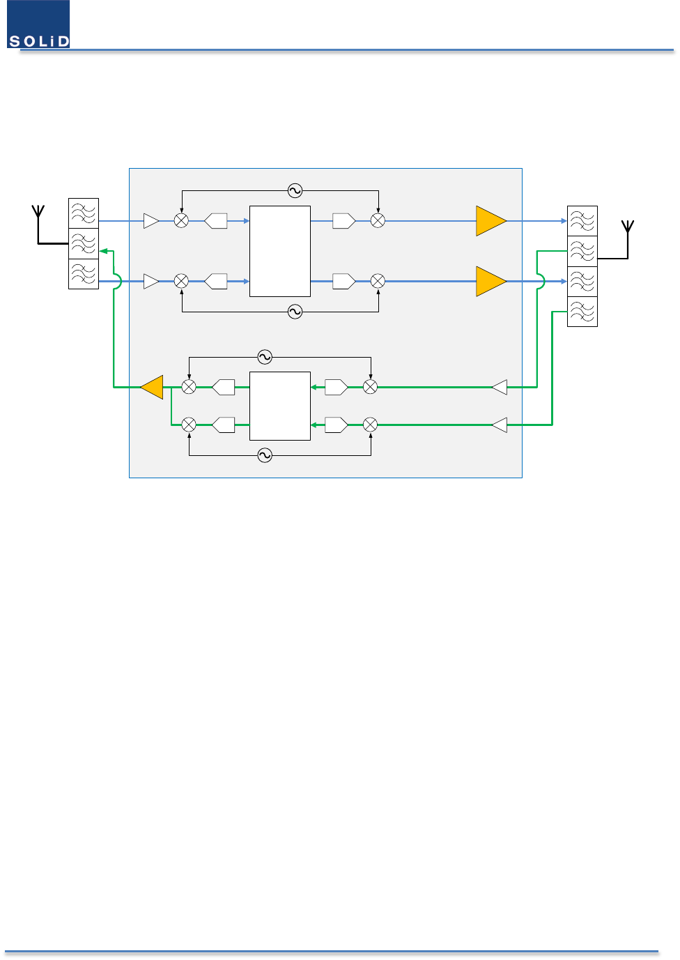
Below is the block diagram which describes the signal flow in the equipment.
PRDU
FPGA-
Downlink
FPGA-
Uplink
Donor
Antenna Service
Antenna
700 PS
800 PS
700 & 800 PS
700 PS
800 PS
700 PS
800 PS
LO1
LO2
LO3
LO4
700 PS
800 PS
Figure 2. Signal Flow of SRDR-33-7080-A-FN
700 PS stands for the signal that includes Public Safety narrowband (6+6 MHz) and the FirstNet (10+10 MHz). 800
PS stands for the signal that includes NPSPAC (3+3 MHz), PS & Non-Cellular SMR (6+6 MHz), and Expansion Band
(1+1 MHz).
Off-the-air RF signal that received from the donor antenna is down-converted to the IF signal. It goes to the FPGA
after the analog-to-digital conversion, and filtered to remove the unwanted signal. The signal that comes from FPGA
is reconstructed in the digital-to-analog converter. And then it would be up-converted by the same local oscillator
with the down-conversion. So, its frequency is same to the original signal.
User Manual of SRDR-33-7080-A
©2017 SOLiD, Inc. All Rights Reserved. Confidential & Proprietary. Page 20 / 70
2.5 Description of Modules
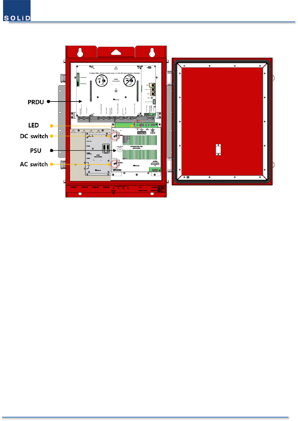
Figure 3. Inner View of the SRDR-33-7080-A-FN
2.5.1 Integrated PSU
The integrated PSU consists of AC to DC power supply, DC to DC power supply, and the 48V battery charger. This
feature enables to operate with AC power source and batteries for redundancy.
2.5.2 Power Amplifier Unit (PAU)
This unit amplifiers a low-power signal to the high-powered RF signal.
2.5.3 Digital Unit (DU)
The unit performs a powerful digital filtering.
2.5.4 Radio Frequency Unit (RFU)
Each signal on the 700 & 800 MHz band is converted into the signal with an intermediate frequency to be filtered.
For high input power it is attenuated to prevent the saturation in the analog-to-digital converter. The signal which
comes from the digital-to-analog converter is also converted into the signal with an original radio frequency.
2.5.5 CPU
This unit controls and monitors every module except for multiplexer. After connecting the product to PC, user set
up parameters to operate via GUI software. And it will monitor and store all status to be chosen.
User Manual of SRDR-33-7080-A
©2017 SOLiD, Inc. All Rights Reserved. Confidential & Proprietary. Page 21 / 70
2.5.6 Multiplexer
Multiplexer combines several signals of multiple paths into those of one path. And it acts vice versa. This module is
made up of cavities.
2.5.7 Signal Analysis Module (SAM)
This is a hardware plug-in module with a high processing power and it enables advanced system analysis, such as:
data logging of wideband spectrum to aid in application of window filters, to spectrum analyzer features that display
near-real time spectrum readings for both input and output.
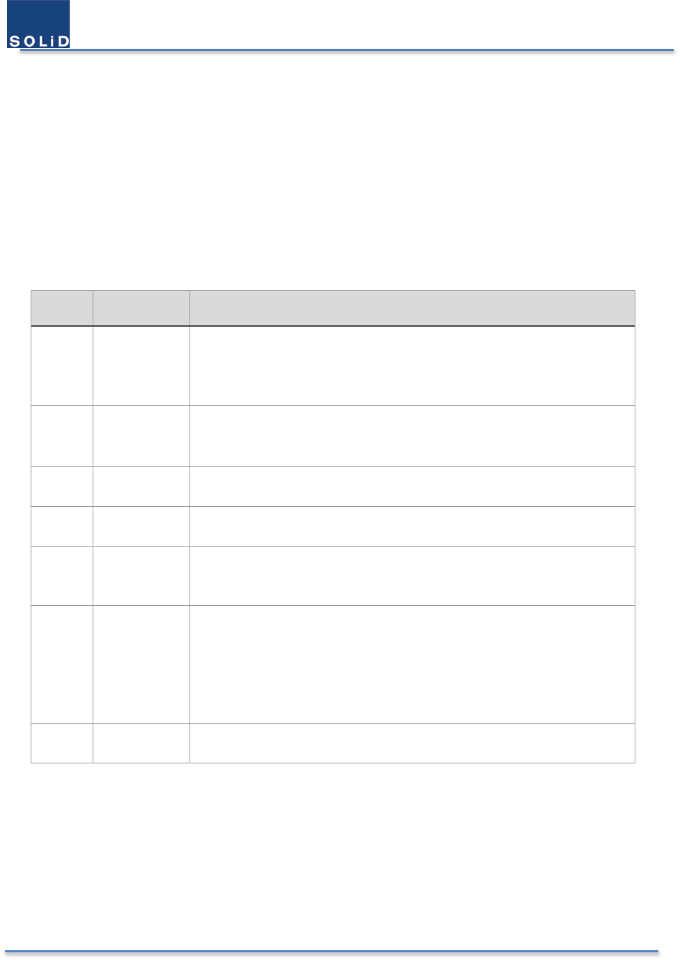
Table 2. Unit Functions
No. Unit Description
1 Integrated
PSU
AC input : 100 – 120 VAC,
DC input: 48 – 56 VDC,
Batteries input: 43 – 56 VDC
Output: 29V, 5V
2 PAU Filters and amplifies highly downlink signals in 700 MHz band irrespetively
Filters and amplifies highly downlink signals in 800 MHz band irrespetively
Filters and amplifies highly uplink signals in 700 MHz band & 800 MHz band
3 DU Filters signals
Cancels echo signals and amplifies original input signals
4 RFU Down-converts and up-converts the frequencies of signals
Attenuates and amplifies signals
5 CPU Controls each unit to operate
Monitors the defined status of each unit
Can be accessed by Ethernet and 2.4 GHz Wi-Fi
6 Multiplexer Separates a downlink signal which comes from the donor antenna into signal
in the 700 band and the signal in the 800 band. And combines vice versa for
uplink signal.
Combines two downlink signals which come from RFU into one signal to the
service antenna and separates vice versa for uplink signal.
7 Enclosure Enclosure to satisfy NEMA4
Can be mounted on the Wall/Rack
User Manual of SRDR-33-7080-A
©2017 SOLiD, Inc. All Rights Reserved. Confidential & Proprietary. Page 22 / 70
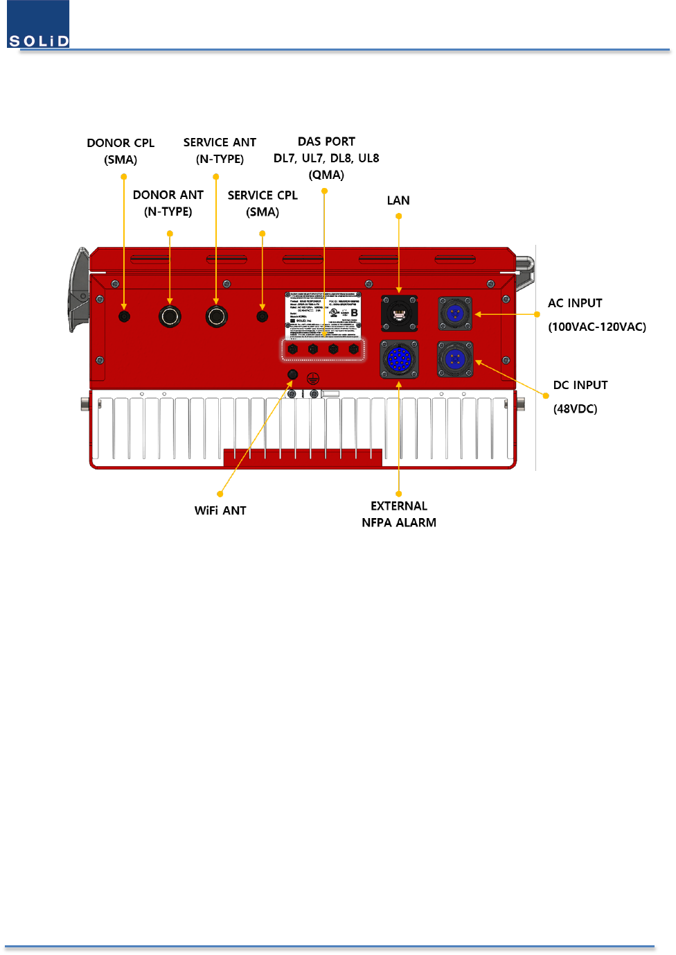
2.6 External Interface
All excternal connectors are located in the bottom side of the product.
Figure 4. External Connectors
User Manual of SRDR-33-7080-A
©2017 SOLiD, Inc. All Rights Reserved. Confidential & Proprietary. Page 23 / 70
2.7 Operation
2.7.1 Classes and Passbands Types
The class of device which is defined in the FCC part 90 is distingushed by the below passbands and each bandwidth
of channel filter. And it is enabled by the digital filter which user can choose approprietly under the cicumstance.
Table 3. Passbands of Class A Device
Bands Category Downlink Uplink
700 MHz PS narrowband 769 – 775 MHz 799 – 805 MHz
800 MHz Public Safety 851 - 861 MHz 806 - 816 MHz
Table 4. Passbands of Class B Device
Bands Category Downlink Uplink
700 MHz LTE 758 – 768 MHz 788 – 798 MHz
PS narrowband 769 – 775 MHz 799 – 805 MHz
800 MHz Public Safety 851 - 861 MHz 806 - 816 MHz
There are 2 different passband types for our equipment. Below is the table which describes the
name and the FCC part 90 Class.
Table 5. Passband Types
License Passband Type Mode Number FCC part 90 Class
Basic
(Band-Selective)
Pre-configured
Band Filters
M701 Class B Device
M702 Class B Device
M703 Class B Device
M801 Class B Device
M802 Class B Device
M803 Class B Device
SRDR-33-L1
(Channel-Selective)
Channelized Filters M036 Class A Device
User Manual of SRDR-33-7080-A
©2017 SOLiD, Inc. All Rights Reserved. Confidential & Proprietary. Page 24 / 70
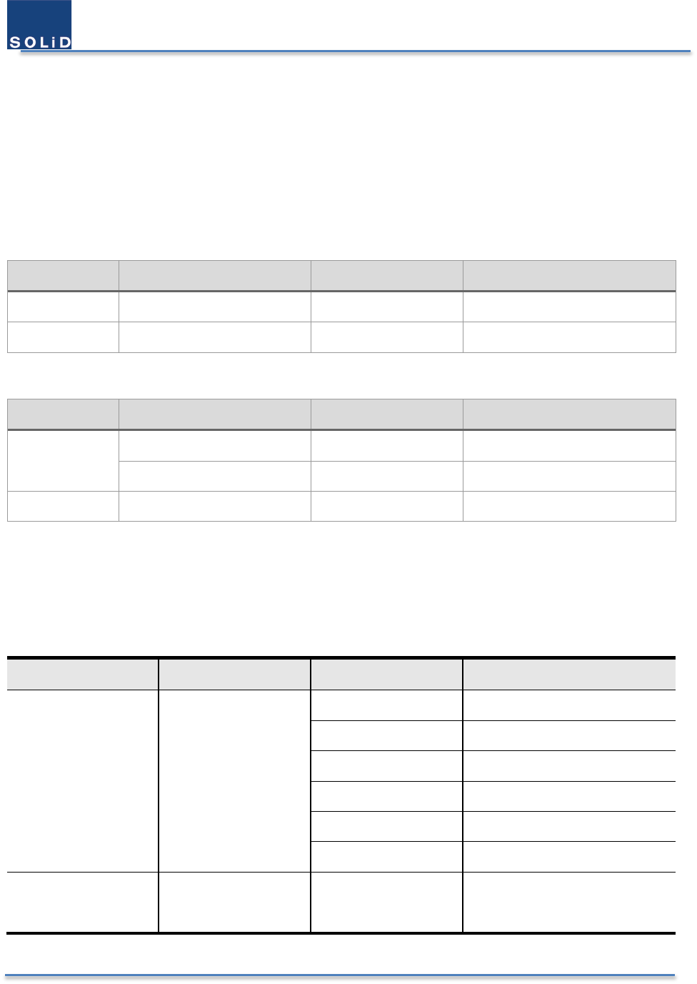
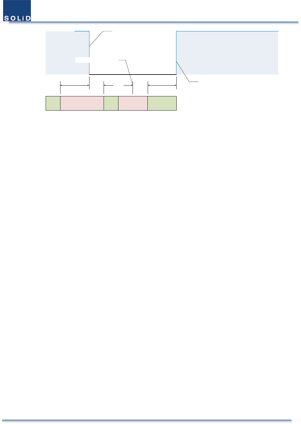
All the spectrum examples per mode numbers are presented below. The blue squares denotes the digital filters, and
the vertical lines in them denotes the radio signals. The dark blue ones are service channels, and the red ones are
interferences.
758 763 768 769 775
788 793 798 799 805
Figure 5. The Spectrum of M701
758 763 768 769 775
788 793 798 799 805
Figure 6. The Spectrum of M702
758 763 768 769 775
788 793 798 799 805
Figure 7. The Spectrum of M703
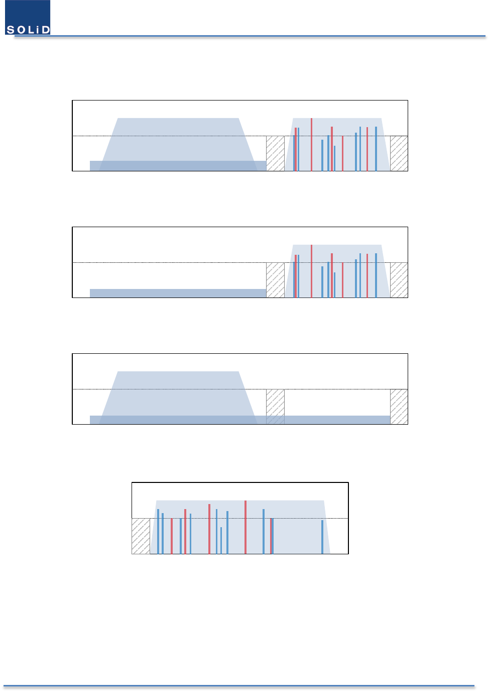
851 854 860 861
806 809 815 816
Figure 8. The Spectrum of M801
User Manual of SRDR-33-7080-A
©2017 SOLiD, Inc. All Rights Reserved. Confidential & Proprietary. Page 25 / 70
851 854 860 861
806 809 815 816
Figure 9. The Spectrum of M802
851 854 860 861
806 809 815 816
Figure 10. The Spectrum of M803
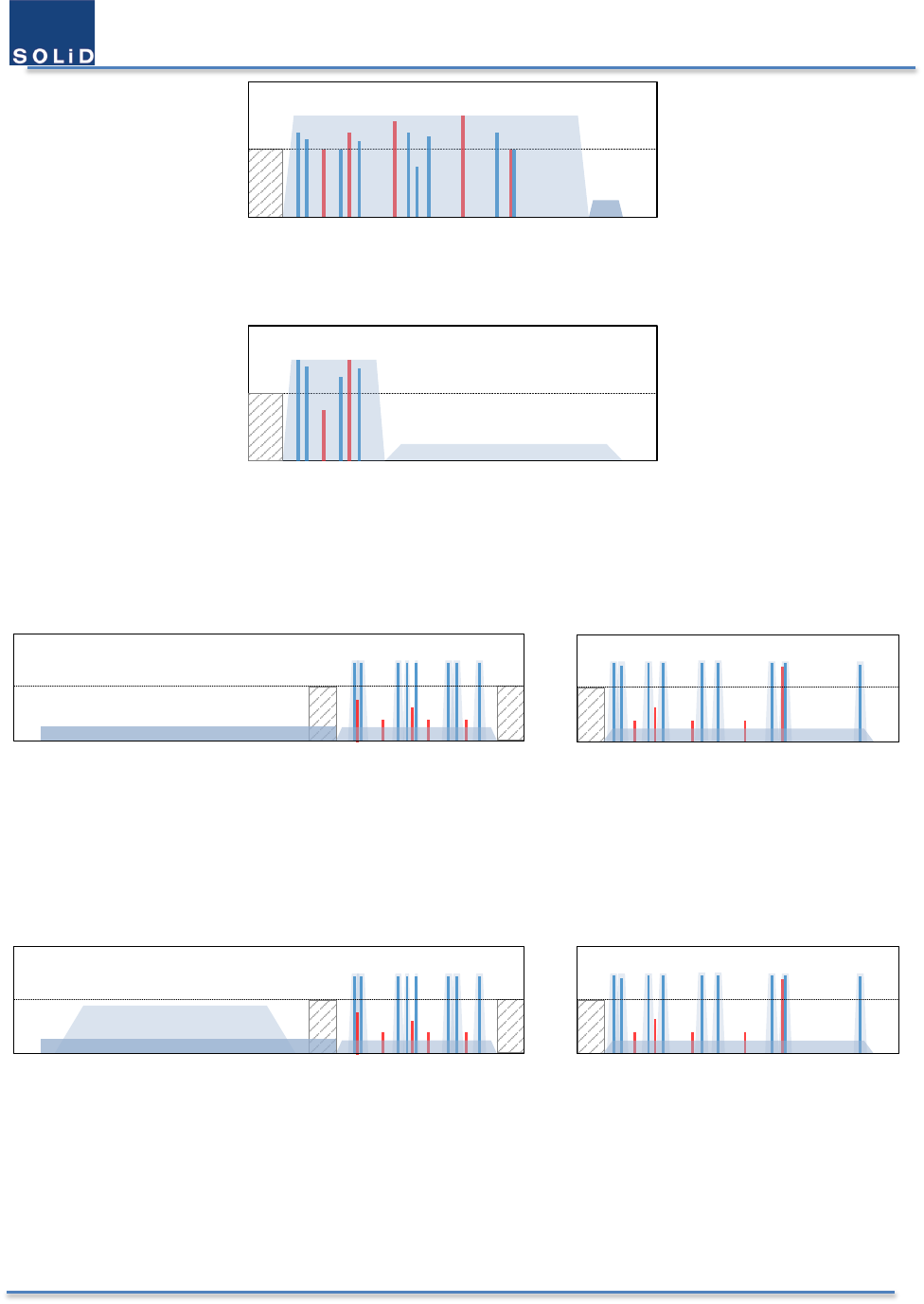
700 Channel-Selective Spectrum excluding FirstNet
758 763 768 769 775
788 793 798 799 805
851 854 860 861
806 809 815 816
800 Channel-Selective Spectrum
Figure 11. The Spectrum of M036 excluding FirstNet
851 854 860 861
806 809 815 816
758 763 768 769 775
700 Channel-Selective Spectrum including FirstNet 800 Channel-Selective Spectrum
788 793 798 799 805
Figure 12, The Spectrum of M036 including FirstNet

User Manual of SRDR-33-7080-A
©2017 SOLiD, Inc. All Rights Reserved. Confidential & Proprietary. Page 26 / 70
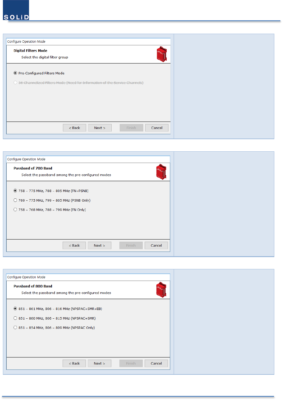
2.7.2 Procedure to Choose Passband
From the GUI for setup the equipment, user can choose one passband type among the possible several alternatives.
It is noticed that a specific passband type named M036 is only available if SRDR-33-L1 license exists. The procedure
of choice passband’s type is executed by the wizard in the GUI.
Below are pictures which are captured in the GUI. User configures digital filters in the step 3.
Step 1
Click Operation
Mode Wizard
Step 2
Choose the service band
User Manual of SRDR-33-7080-A
©2017 SOLiD, Inc. All Rights Reserved. Confidential & Proprietary. Page 27 / 70
Step 3-1
Choose the passband types
among the 3 options.
Pre-configured Filter
A step is followed by step 3-1
Choose the detailed passband
option among the pre-
configured filters in Public
Safety 700 MHz band.
Another step is followed by step 3-1
Choose the detailed passband
option among the pre-
configured filters in Public
Safety 800 MHz band.
User Manual of SRDR-33-7080-A
©2017 SOLiD, Inc. All Rights Reserved. Confidential & Proprietary. Page 28 / 70
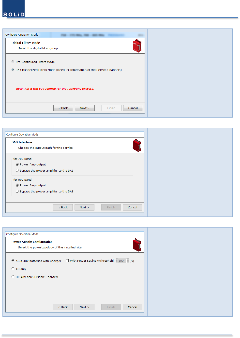
Step 3-2
Choose the passband types
among the 3 options.
36 Channelized Filter
Step 4
Choose the DAS Interface
choose the output port to the
service antenna
Step 5
Choose the power supply
configuration
choose the redundancy type
of power source
User Manual of SRDR-33-7080-A
©2017 SOLiD, Inc. All Rights Reserved. Confidential & Proprietary. Page 29 / 70
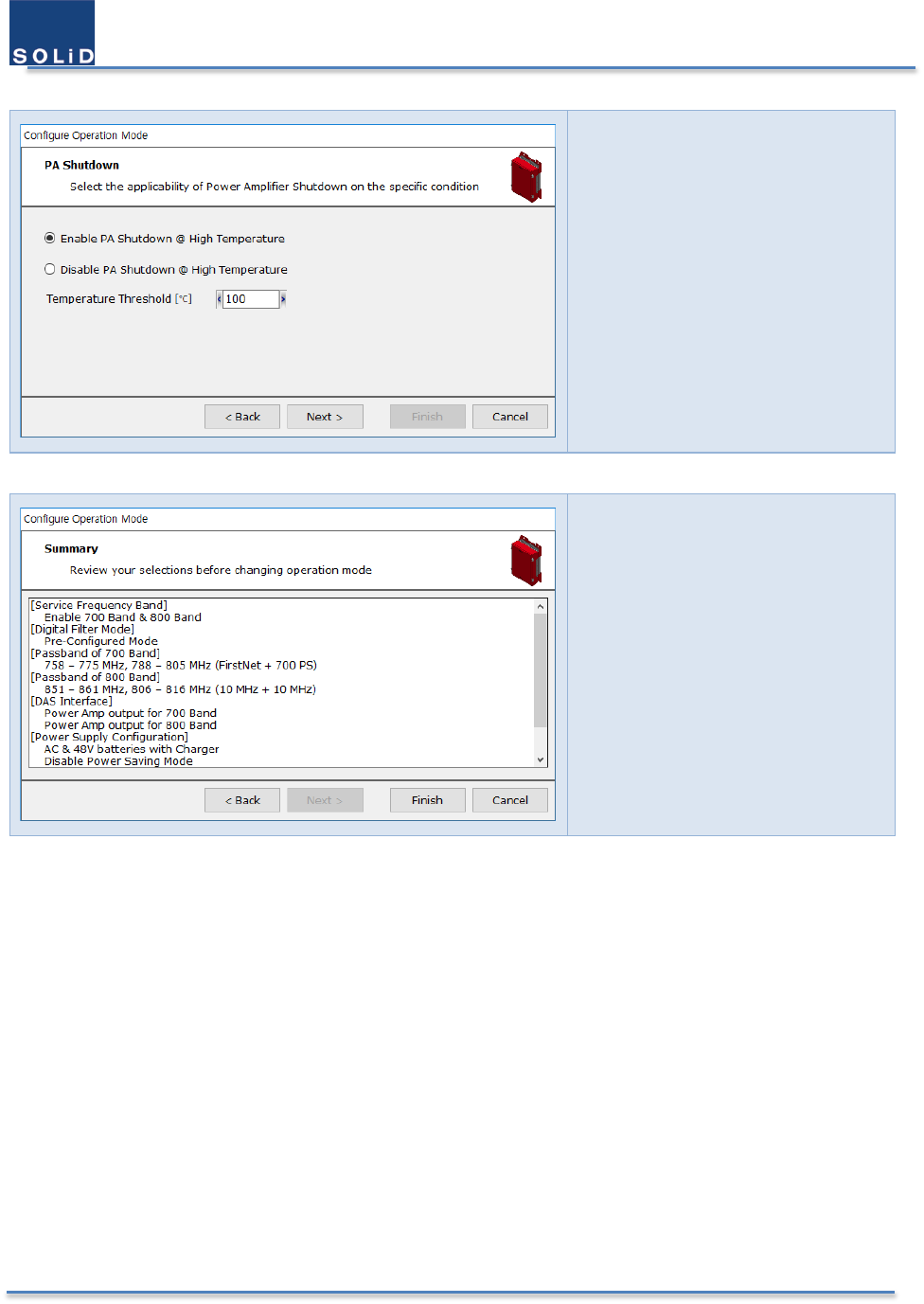
Step 6
Select Power Amplifier’s
Shutdown for the specific region
Step 7
Report the summary of the user
selection.
User Manual of SRDR-33-7080-A
©2017 SOLiD, Inc. All Rights Reserved. Confidential & Proprietary. Page 30 / 70
2.7.3 Automatic Shutdown of Amplifiers
The equipment has an automatic shutdown function to protect the power amplifiers themselves and the wireless
network when the normal operational conditions cannot be maintained. The conditions of the shutdown RF power
amplifier are below.
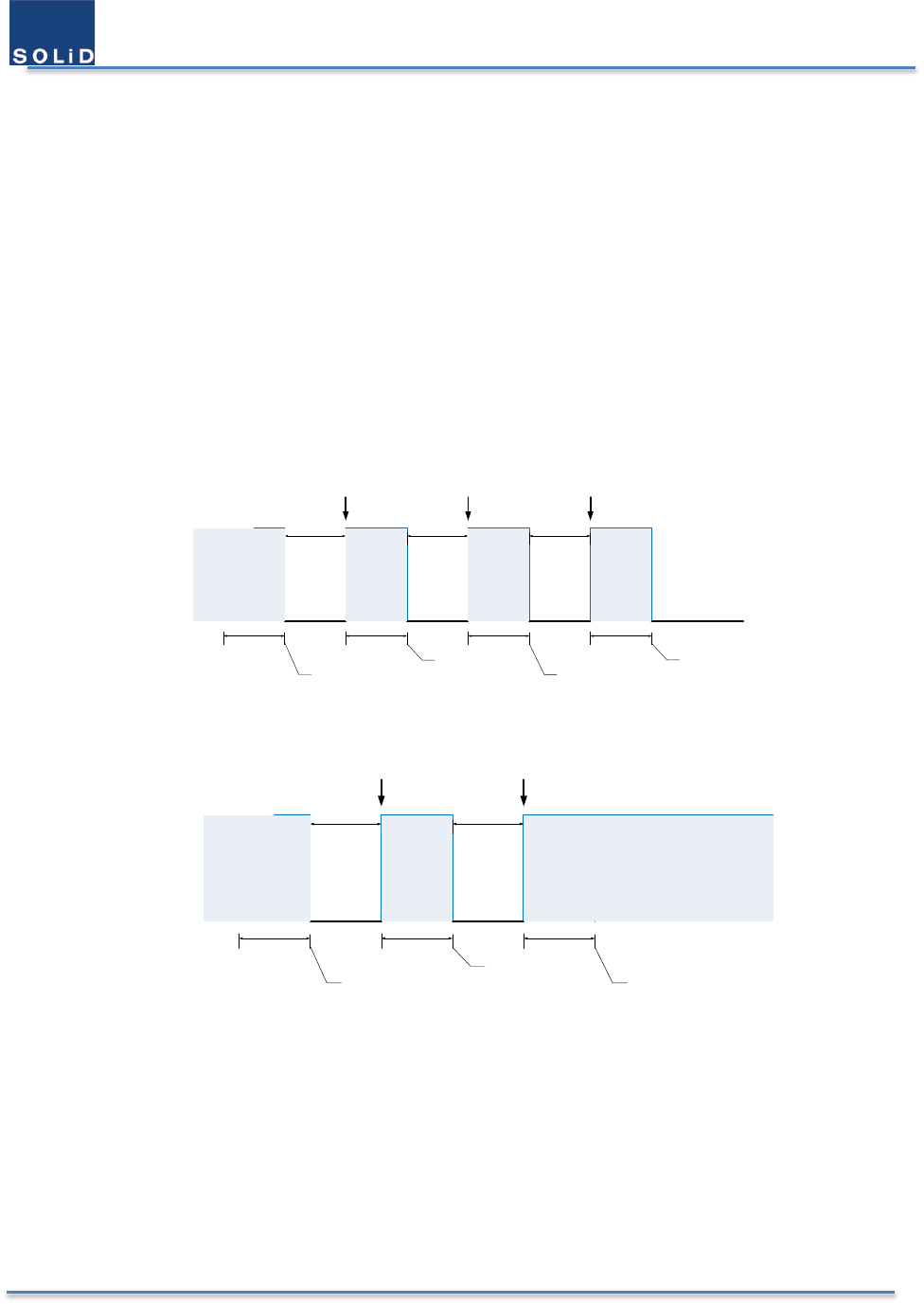
A. High Output Power from RF Power Amplifier (Shutdown Algorithm type 1)
The equipment shut down the power amplifier automatically if the composite output power exceed the threshold
level for 10 seconds. The level can be set through GUI. Once an automatic shutdown occurs, the equipment will turn
on power amplifier automatically in 10 seconds to assess the power amplifier’s condition. If the shutdown condition
is detected again, the equipment will shut down the power amplifier. It tries to do this process up to 3 times. If the
shutdown condition is released, it continues to operate. After an automatic shutdown occurs 3 times continuously,
an automatic recovery is terminated. So, to turn on power amplifier is only possible by setting PA operation in the
GUI. The following diagram shows this shutdown algorithm type 1.
1st recovery 2nd recovery 3rd recovery
10 sec
1st alarm is detected
2nd alarm is detected
3rd alarm is detected
4th alarm is detected
10 sec10 sec10 sec
10 sec 10 sec 10 sec
PA on PA on PA onPA on
Normal Operation
Shutdown
Shutdown
Figure 13. 3 times Failure in Shutdown Algorithm Type 1
1st recovery 2nd recovery
1st alarm is detected
2nd alarm is detected
3rd alarm is released
10 sec10 sec10 sec
10 sec 10 sec
PA on PA onPA on
Shutdown
Normal Operation
Figure 14. 2 times Failure in Shutdown Algorithm Type 1
B. High Input Power from RF Power Amplifier (Shutdown Algorithm type 2)
The equipment shut down the power amplifier automatically if the composite input power exceed the threshold
level for 10 seconds. The level can be set through GUI. Once an automatic shutdown occurs, if only the shutdown
condition is released, the equipment would turn on power amplifier automatically. The following diagram shows this
shutdown algorithm type 2.
User Manual of SRDR-33-7080-A
©2017 SOLiD, Inc. All Rights Reserved. Confidential & Proprietary. Page 31 / 70
Shutdown occurs
10 sec
10 sec
PA onPA on
Shutdown
Normal Operation
Alarm No alarmAlarm
10 sec
Status
Release Shutdown
No Release Shutdown
Figure 15. Shutdown Algorithm Type 2
C. High Temperature at RF Power Transistor (Shutdown Algorithm type 2)
The equipment shut down the power amplifier automatically if the composite input power exceed the threshold
level for 10 seconds. The level can be set through GUI. Once an automatic shutdown occurs, if only the shutdown
condition is released, the equipment would turn on power amplifier automatically. The following diagram shows this
shutdown algorithm type 2.
User Manual of SRDR-33-7080-A
©2017 SOLiD, Inc. All Rights Reserved. Confidential & Proprietary. Page 32 / 70
3 Installing the SOLiD RESPONDER
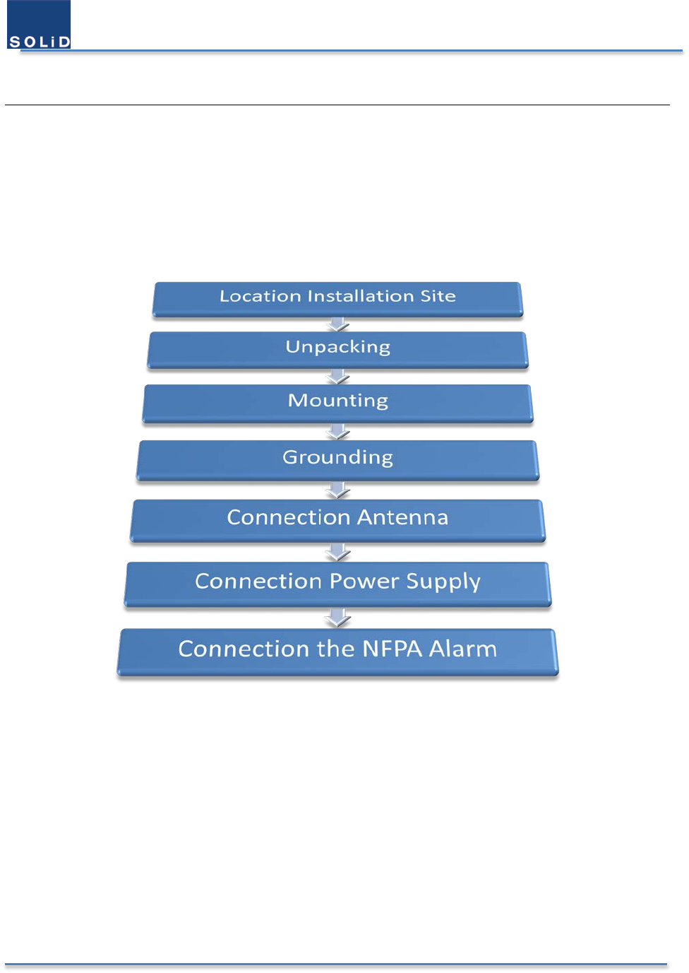
3.1 Overview of the Installation Procedure
User Manual of SRDR-33-7080-A
©2017 SOLiD, Inc. All Rights Reserved. Confidential & Proprietary. Page 33 / 70
3.2 Location Installation Site
3.2.1 Product Dimension
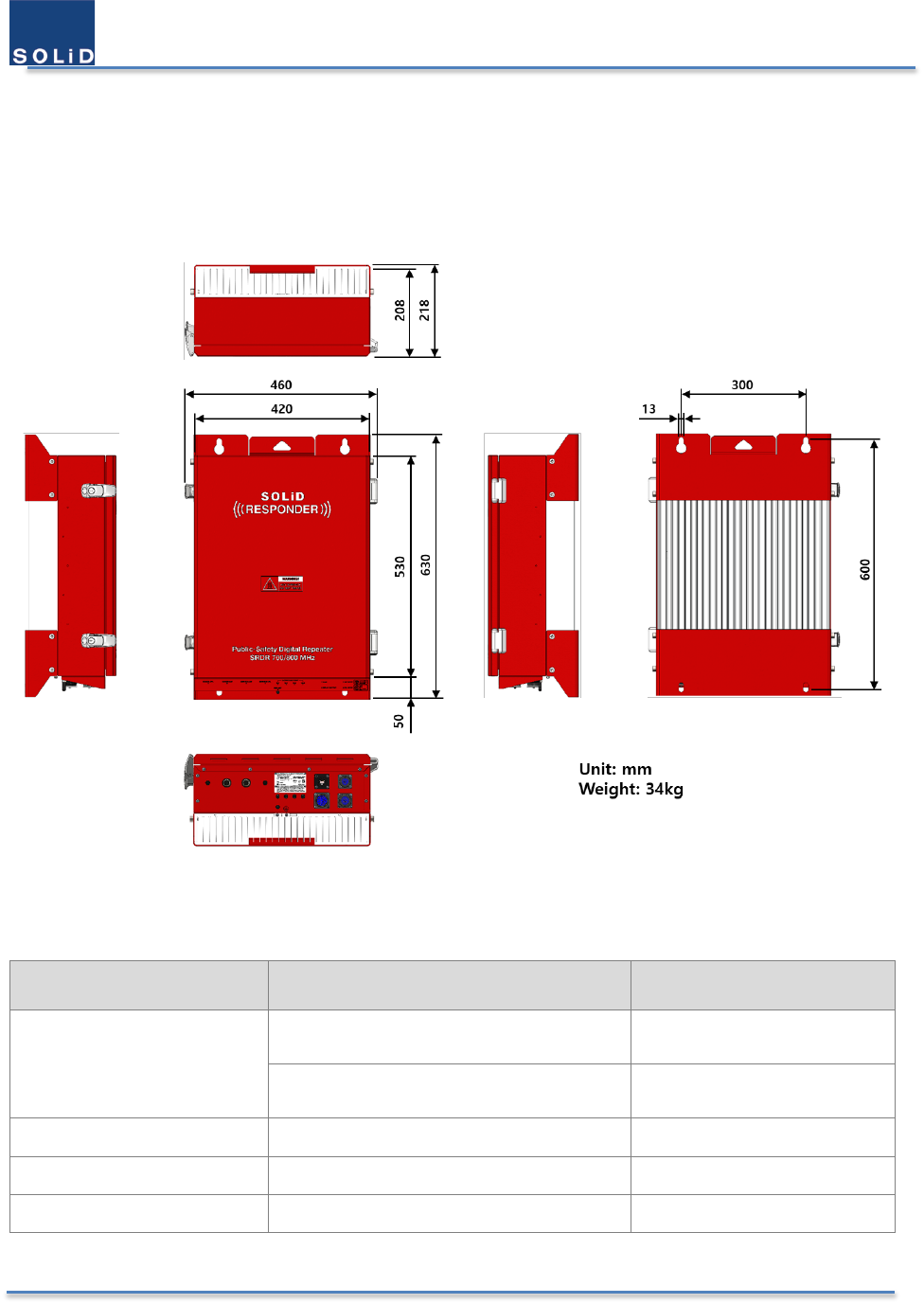
Below are the dimensions of SRDR-33-7080-A-FN.
Figure 16. Dimensions of SRDR-7080-A-FN
Table 6. Mechanical Specification
Items
Value
Comments
Dimensions (HxWxD)
530 x 420 x 208 (mm)
20.9 x 16.5 x 8.2 (inches)
Without bump
630 x 460 x 218 (mm)
24.8 x 18.1 x 8.6 (inches)
With bump
Weight 34kg, 75 lb
19” Rack Mount Yes
Operating Temperature -30 – 60 °C Ambient Temperature
User Manual of SRDR-33-7080-A
©2017 SOLiD, Inc. All Rights Reserved. Confidential & Proprietary. Page 34 / 70
3.2.2 Installation Environment
The following criteria should be considered when selecting the SOLiD Responder installation site location. During
transportation and installation, take necessary handling precautions to avoid potential physical injury to the
installation personnel and the equipment.
Input Signal Requirements
BTS channels, channel power
BTS antenna location, height, gain
Distance from the BTS antenna
Donor antenna type, gain, and location
It is recommended that the installation location be as close as possible to the donor antenna site in order
to reduce the cable loss to a minimum.
Environmental Requirements
Use a suitable mounting surface, such as a flat back rigid wall. The SOLiD Responder can be mounted to
the 19” rack.
The SOLiD Responder is convection cooled, so airflow should be possible.
Electrical Requirements
Follow Electro-Static Discharge (ESD) precautions.
Verify that the equipment has been well grounded. This includes antennas and all cables connected to the
system. Ensure lightning protection for the antennas is properly grounded.
The power up procedure should be followed by the connecting all components arould the SOLiD
Responder to prevnet from the electrical damage.
Ensure cables are properly routed and secured so that they are not damaged.
3.3 Unpacking and Package Contents
Examine the packing container for damage before unpacking the product. After unboxing, verify that all of the items
listed in the packing list are included.
Table 7. Packing List of the SRDR-33-7080-A-FN
No. Items Quantity Description
1 SRDR-33-7080-A-FN 1 The main body of equipment
This includes the keys of door insideof door.
2 AC Cable 1 Power cable for AC 100 – 120 VAC
3 DC Cable 1 Power cable for DC 48VDC and 48V line batteries
4 NFPA Alarms Cable 1 External alarms cable for NFPA alarm box.
It includes 5 possible alarms which are chosen by user.
5 Water-proof RJ-45
Connector
1 Accessory for the Ethernet cable to connect with the equipment.
For SNMP traps.
User Manual of SRDR-33-7080-A
©2017 SOLiD, Inc. All Rights Reserved. Confidential & Proprietary. Page 35 / 70
3.4 Mounting the Product
3.4.1 Mounting Method
SRDR-33-7080-A-FN is designed to be water-proof and dirt-proof. The unit has the structure of One-Body enclosure.
It satisfies water-proof and quake-proof standards equivalent of NEMA4.
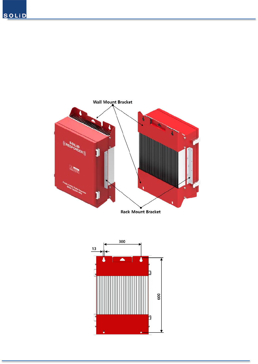
SOLiD RESPONDER can be mounted into either of a 19” Standard Rack or on a Wall. Basically, it has both of a Wall
Mount Bracket and a Rack Mount Bracket. Depending on the use of the Rack Mount Bracket, the bracket can be
removed. The following shows dimension of the fixing point for the Wall Mount Bracket.
Figure 17. Mount Bracket for Wall and Rack
Figure 18. Dimensions used to install Product on the Wall
User Manual of SRDR-33-7080-A
©2017 SOLiD, Inc. All Rights Reserved. Confidential & Proprietary. Page 36 / 70
3.4.2 Installation the Wall Mount Bracket
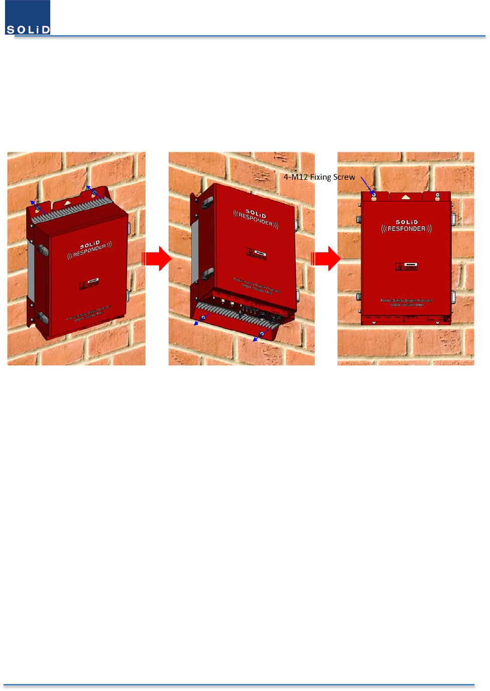
SRDR-33-7080-A-FN installation bracket is attached on Enclosure when is delivered. It doesn’t need to remove
bracket to install enclosure. simply after installing 4 of M12 mounting bolts, secure 4 mounting bolts tightly
First, install 2 of M12 mounting bolts roughly half way on the enclosure and install enclosure over the bolts and
secure tightly.
Second, install 2 of M12 mounting bolts under the enclosure and secure tightly
3.4.3 Rack Mount Installation
SOLiD RESPONDER would be the best fit to be mounted on 19” standard rack. into a rack. The unit occupies around
15U of space except cable connection.
3.5 Grounding
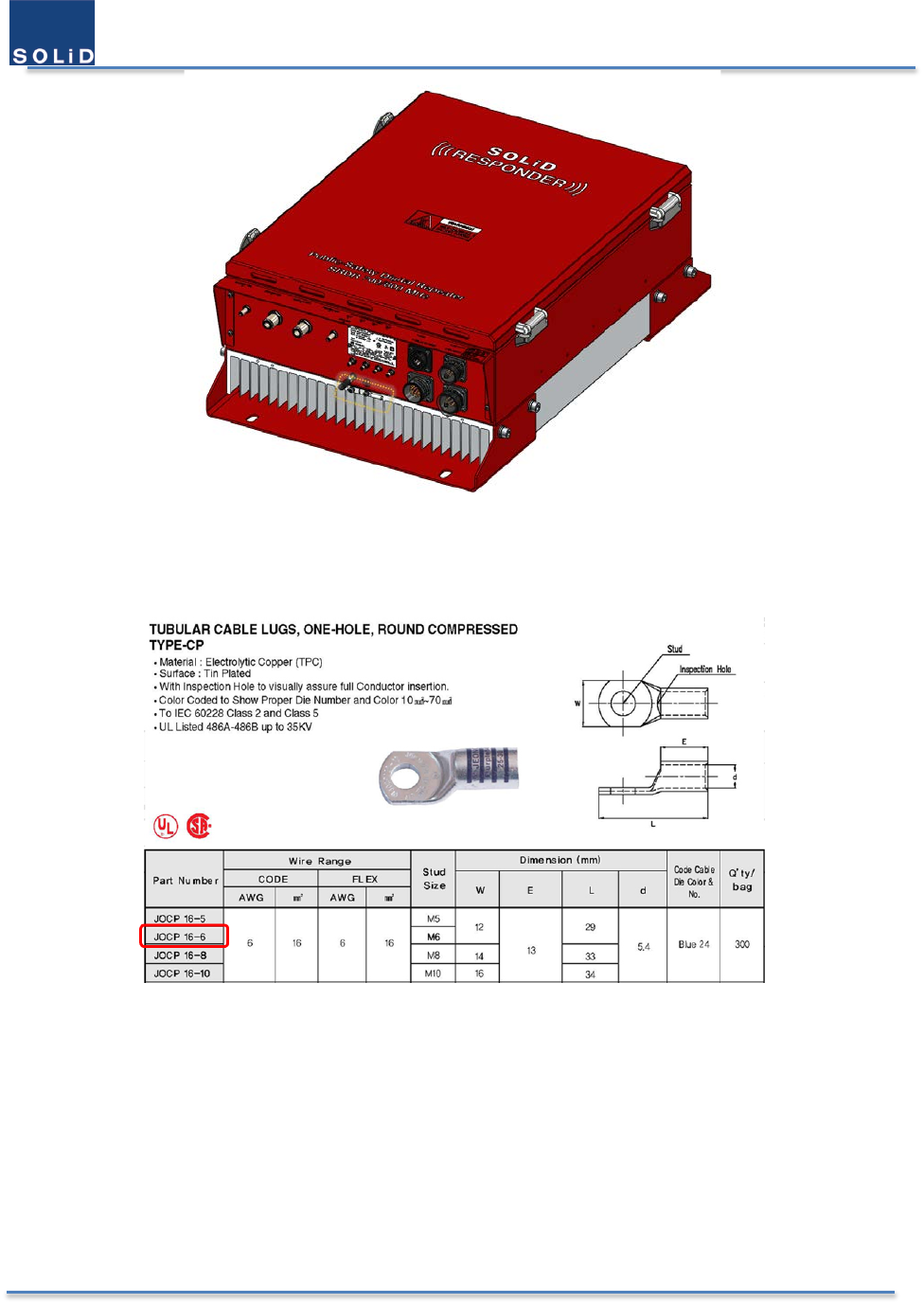
The Grounding terminal is located at the bottom of heat-dissipating pin in the back of enclosure, and it’s fixed by M4
screw. The recommended thickness of cable is AWG#10 – 12 copper grounding wire.
User Manual of SRDR-33-7080-A
©2017 SOLiD, Inc. All Rights Reserved. Confidential & Proprietary. Page 37 / 70
Figure 19. The Location of Ground Lug
The specification of compression terminal is like below.
Figure 20. Information of Terminal
The required part number is JOCT 6-2 supporting AWG 12 – 10. The way to install the grounding cable comply with
below procedures.
1. Loosen a M4 screws and then take compression terminal off
2. Insert AWG#12~10 Grounding Wire into terminal and then compress a terminal using tool
3. Assemble the terminal which made in step “2” using M4 screws
4. Cut the ground wire to proper length and connect it to the earth ground source ( Round terminals located
on the side of a 1 mm2 (6 AWG) or more wires Using permanently connected to earth.)

User Manual of SRDR-33-7080-A
©2017 SOLiD, Inc. All Rights Reserved. Confidential & Proprietary. Page 38 / 70
3.6 Antenna Connections and Guidelines
3.6.1 Donor Antenna Installation Guidelines
Accurately determine the azimuth to the donor site. Obtain the donor site information and approval from
the service provider/carrier.
Ensure that the radiation path to the donor site is unobstructed.
Mount the donor antenna at or toward the edge of the roof, in the direction of the donor site. Avoid having
the RF signal from the donor pass above the location(s) of the service antennas. Normally, the service
antennas are installed behind and below the donor antenna, as viewed from above. This approach helps
avoid interference and feedback to and from the service antennas.
Normally, mounting the donor antenna higher will allow a less obstructed path to the donor site. However,
in high traffic metro areas, avoid mounting the donor antenna higher than necessary, as the quality of the
donor signal may become less stable and it is more likely to encounter adjacent channel interference.
When possible, shield the rear of a donor antenna by locating it so that any HVAC units and/or penthouse
structures are behind the antenna, relative to the donor cell site location.
3.6.2 Indoor Antenna Installation Guidelines
Use omnidirectional antennas indoors and locate them centrally with respect to the intended coverage
area to minimize signal leakage to the outside. Only use directional antennas indoors in special cases when
higher gain and directionality would be helpful and RF exposure limits will not be exceeded.
To avoid Signal Booster uplink overload and gain limiting, mount the indoor antennas away from areas
where mobile subscribers frequently use their phones, such as desks or dispatch areas.
To determine the quantity and locations of indoor antennas, measure Received Signal Strength Indication
(RSSI) using DM Tool software to determine areas of weak signals. These are the approximate areas where
indoor antennas may be needed.
Be aware that the signal from an indoor antenna, in most cases, can be expected to penetrate
approximately two standard sheet rock walls to reach users. If the signal must travel through more than
two walls, or if the walls are made of materials other than sheet rock, it may be necessary to split the
available signal and add more antennas.
3.6.3 RF Cable Installation Guidelines
For all coaxial connections to/from the Signal Booster - high performance, flexible, low loss 50 ohm coaxial
communications cable.
All cables shall be weather-resistant type.
If the coaxial cables are NOT weather-resistant type: wrap the exterior coaxial cables with insulation and
holding tape (Type 3M Rubber splicing tape) for environmental protection and to ensure longer lifetime.
Cable length - determined by the Signal Booster installation plan. When calculating the cablelength, take
into account excess cable slack so as not to limit the insertion paths.
3.6.4 Connecting Antennas
Connect the Donor and Service antennas.
Verify all RF connectors are tightened and the cables and antennas are secured.
User Manual of SRDR-33-7080-A
©2017 SOLiD, Inc. All Rights Reserved. Confidential & Proprietary. Page 39 / 70
3.7 Connecting Power Cables and Power-up
3.7.1 Integrated PSU
The integrated PSU consists of AC to DC power supply, DC to DC power supply, and the 48V battery charger. This
feature enables to operate with AC power source and batteries for redundancy. Two external ports such as AC input
and DC input have circuit breaker to protect themselves. Below is the table for the power supply specification.
Table 8. Power Supply Specification
Item Description
Power
Supply
AC 100 - 120 VAC
DC
48 – 56 VDC
Charger 48V-rail charger for lead-acid batteries
with State of Charge detection
3.7.2 Power Redundancy
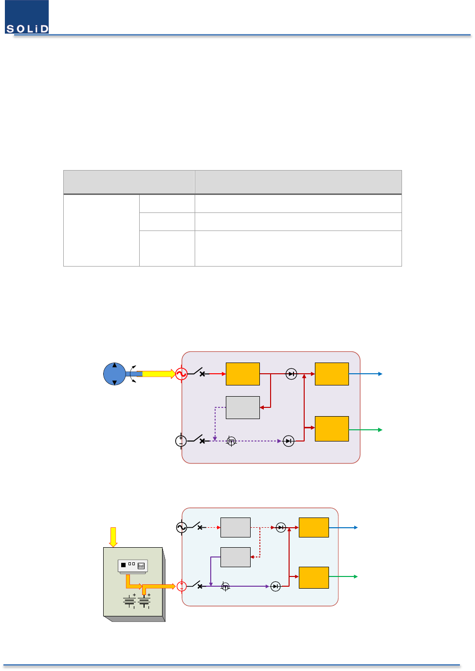
SRDR-33-7080-A-FN supports AC 120V power source, 48V DC power source, DC 48V batteries and charger. So 3 types
of power supply configuration are possible for power redundancy. These block diagrams are below.
100 - 120 VAC
AC
DC
AC/DC
Charger
DC/DC
29V
DC/DC
5V
29 V
5.0 V
AC – UPS
Low Voltage
Disconnect
CB2
CB1
Integrated PSU
Figure 21. Connection for AC-UPS site
AC
DC
43 ~ 56 VDC
AC/DC
Charger
DC – UPS
DC/DC
5V
29 V
5.0 V
Battery Enclosure
Low Voltage
Disconnect
DC/DC
29V
CB1
CB2
SLA
Batteries
Integrated PSU
Figure 22. Connection for DC-UPS site
User Manual of SRDR-33-7080-A
©2017 SOLiD, Inc. All Rights Reserved. Confidential & Proprietary. Page 40 / 70
SLA Batt ery
SLA Batt ery
SLA Batt ery
SLA Batt ery
100 - 120 VAC
AC
DC
43 ~ 56 VDC
AC/DC
Charger
DC/DC
5V
Low Voltage
Disconnect
DC/DC
29V
CB2
CB1
AC & Batteries
29 V
5.0 V
Integrated PSU
Figure 23. Connections with AC & Batteries
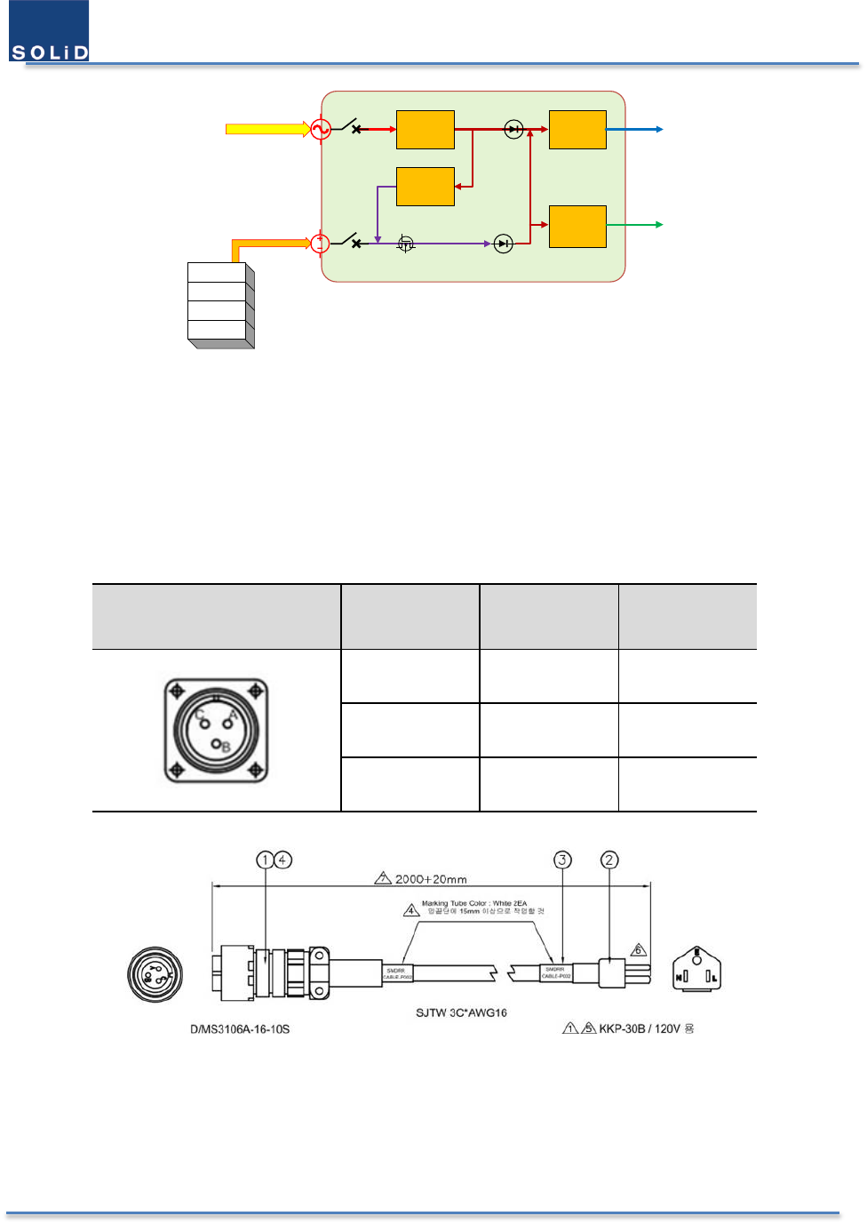
3.7.3 AC Power Cabling
SRDR-33-7080-A-FN supports 100 – 120 VAC input power. The pin discription of AC port is below.
Table 9. AC Port Pin Description
Port Outlook MS Connector
Numbering Name Description
A AC 120V-H AC Hot
B AC 120V-N AC Neutral
C AC GND AC Ground
Figure 24. AC Cable Drawing
A provided outside power cable is only one type with AWG#16 & 2m. From the above drawing you can verify it easily.
Note that you should match exact polarity of AC voltage. If you use the attached AC cable in the shipping box, you
don’t need to worry about it. Otherwise the equipment can have an severe damage under power-on. Usually a circiut
breaker on AC power line will work to prevent damage under the abnormal situation.
User Manual of SRDR-33-7080-A
©2017 SOLiD, Inc. All Rights Reserved. Confidential & Proprietary. Page 41 / 70
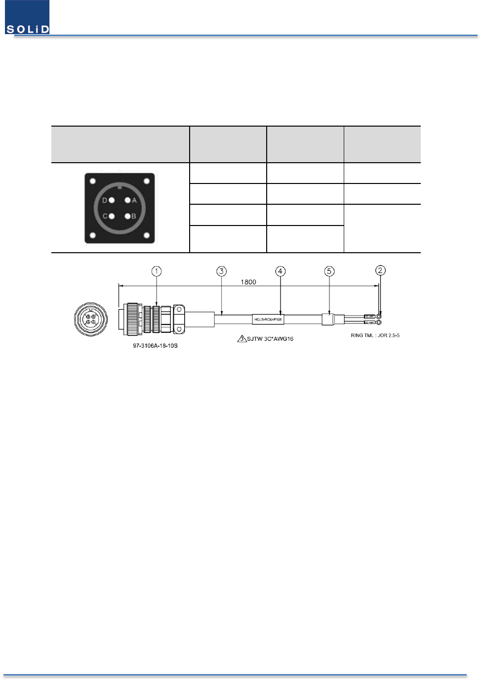
3.7.4 DC Power Cabling
SRDR-33-7080-A-FN supports 48VDC input power. An actual voltage is 43 – 56 VDC of batteries or DC-UPS. The pin
discription of DC port is below.
Table 10. DC Port Pin Description
Port Outlook MS Connector
Numbering Name Description
A NC Not Connected
B NC Not Connected
C
+
48VDC
D
-
Figure 25. DC Cable Drawing
The provided outside power cable is only one type. From the above drawing you can verify it easily.
Note that you should match exact polarity of DC voltage. Otherwise the equipment can have an severe damage
under power-on.
3.7.5 Power Up
After verifying the proper connection of wires in the each power cable, power up SRDR-33-7080-A-FN. Don’t miss
gounding. If an abnormal electrical situation occurs, each circiut breaker on two power lines will work to prevent
damage. If you succeed in power up the product, you can see the green LED on the top of the integrated PSU light.
AC power source has a priority over DC power source in the SRDR-33-7080-A-FN. So, in case that two power switches
are on, the power up from the DC power source wouldn’t performed. You should check the availablity of DC power
source with AC power switch off.
User Manual of SRDR-33-7080-A
©2017 SOLiD, Inc. All Rights Reserved. Confidential & Proprietary. Page 42 / 70
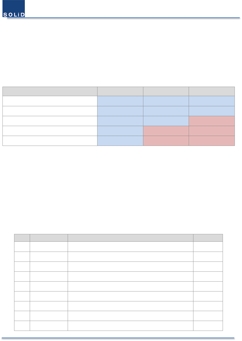
3.8 Connecting NFPA Alarms
3.8.1 Choose the alarms to be monitored
SOLiD Responder provides upto 5 alarms to be monitored by the external alarm box and SNMP traps. They consist
of 2 system alarms and 3 power alarms. Below is the alarms to be provided by the external alarm cable.
Table 11. NFPA Alarm Connection upon the Power Supply configuration
Items
AC & Batteries
AC UPS
DC UPS
System component malfunction. Connect Connect Connect
VSWR-antenna malfunction Connect Connect Connect
Normal AC power, Loss of normal AC power Connect Connect Do Not connect
Battery charger failure Connect Do Not connect Do Not connect
Low battery capacity Connect Do Not connect Do Not connect
Accrding to the power supply configuration, the related 3 power alarms are monitored and masked suitably. But
user should connect the proper alarms because the each external alarm signal is dedicated to the fixed wire in the
cable, and it’s unchanged by software. Below is the proper connection of relat output cable with alarm box upon the
power supply configuration.
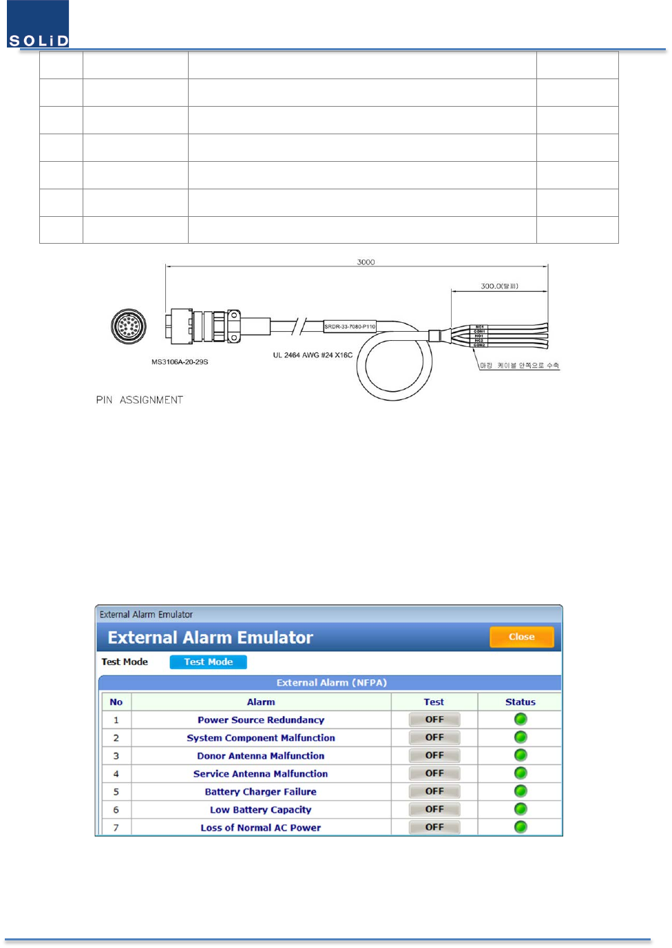
3.8.2 Select the type of external alarms
SOLId RESPONDER provides 3 pins per every alarm. The first one is a common signal, the second one is normal-open
signal, and the third is normal-close signal. Since the alarm state is desired to be sustained under the unpowered
situation, 3 wires per an alarm are adopted instead of programmable 2 wires. So, a customer just have to choose an
appropriate signal according to the type of alarm box. Below is the table describing the pinout of the relay output.
User can recognize the proper wire easily due to the labeling with numbers and colors.
No.
Pin Name
Description
label
1 NC1 A Normal-Closed Signal for System Malfunction A
2 COM1 A Common Signal for System Malfunction B
3 NO1 A Normal-Open Signal for System Malfunction C
4 NC2 A Normal-Closed Signal for Antenna Malfunction D
5 COM2 A Common Signal for Antenna Malfunction E
6 NO2 A Normal-Open Signal for Antenna Malfunction F
7 NC3 A Normal-Closed Signal for AC loss G
8 COM3 A Common Signal for AC loss H
9 NO3 A Normal-Open Signal for AC loss J
User Manual of SRDR-33-7080-A
©2017 SOLiD, Inc. All Rights Reserved. Confidential & Proprietary. Page 43 / 70
10 NC4 A Normal-Closed Signal for a charger failure K
11 COM4 A Common Signal for a charger failure L
12 NO4 A Normal-Open Signal for a charger failure M
13 NC5 A Normal-Closed Signal for the state of charge 70% N
14 COM5 A Common Signal for the state of charge 70% P
15 NO5 A Normal-Open Signal for the state of charge 70% R
16 GND Signal Ground S
Figure 26. Relay Output Cable Drawing
3.8.3 Connect cable to the alarm box
3.8.4 Verify the state of connection
When a user needs to create external alarms on purpose or for testing, additional feature as shown below can be
used. External Alarm Emulator can be found in the top side of Log/Alarm window in the GUI.
Figure 27. External Alarm Emulator
When you click the ON/OFF button in the window, External Alarm Emulator generates the virtual alarm to be
verified. You can see the result in the status LED or in the alarm box. When the External Alarm Emulator window is
closed, to emulate alarms will be cleared.
User Manual of SRDR-33-7080-A
©2017 SOLiD, Inc. All Rights Reserved. Confidential & Proprietary. Page 44 / 70
4 Setup and Commissioning
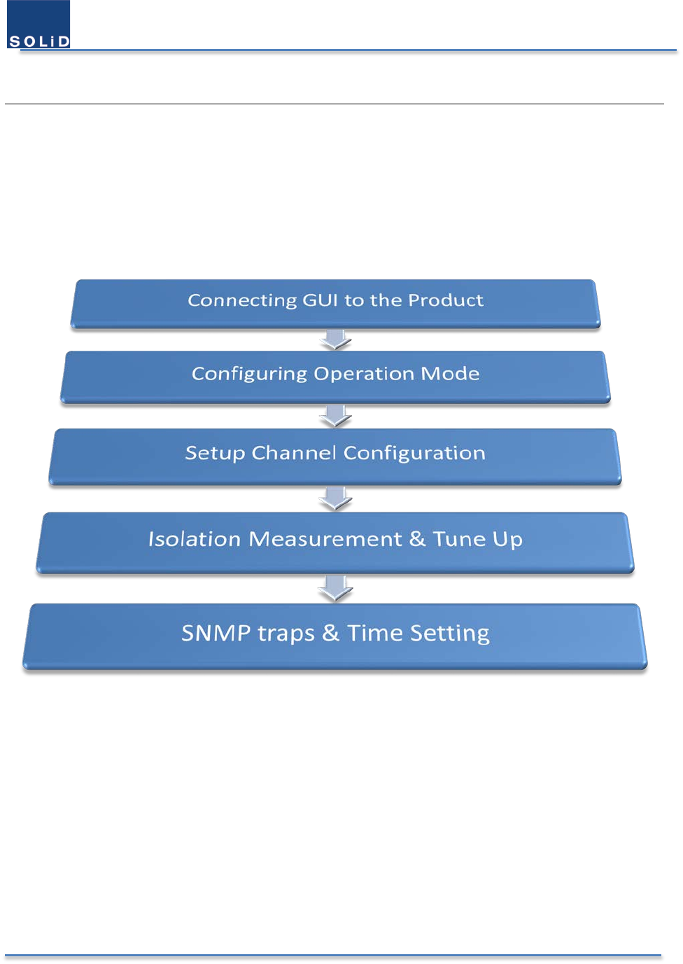
4.1 Overview of the Commissioning Procedure
User Manual of SRDR-33-7080-A
©2017 SOLiD, Inc. All Rights Reserved. Confidential & Proprietary. Page 45 / 70
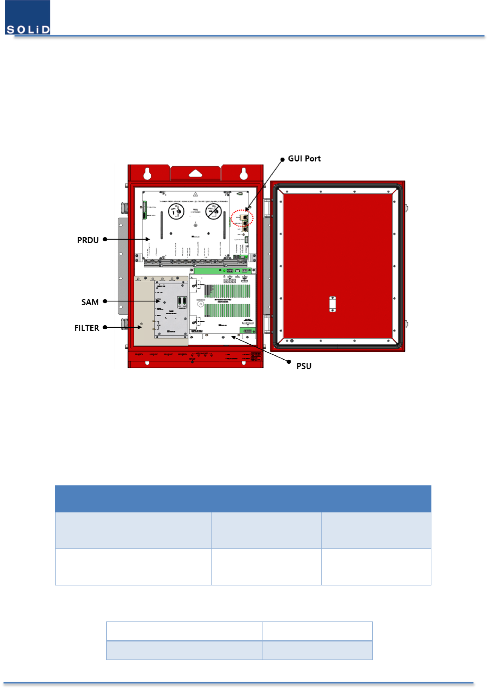
4.2 Connecting the GUI to the Product
4.2.1 Network Information of GUI
The computer where the GUI has been installed can be connected with SOLiD Responder through wireless or wired
connection. Below is the figure of the wired connection port.
Figure 28. GUI Port of SOLiD Responder
SOLiD Responder has the built-in 2.4GHz Wi-Fi module so that a wireless connection is available without the cable.
The computer should be located within the coverage range of 2.4 GHz Wi-Fi, typically hundred feet away. However,
if there are obstacles between them, that could affect the communications.
Table 12. IP address of SOLiD Responder
Type IP Address Port Number
Wired Connection
Via Ethernet (GUI port) 192.168.100.1 20000
Wireless Connection
Via 2.4GHz Wi-Fi 192.168.30.1 20000
Table 13. Access Information to AP
SSID of AP
SOLiD_PS_####
Access Password 12345678
User Manual of SRDR-33-7080-A
©2017 SOLiD, Inc. All Rights Reserved. Confidential & Proprietary. Page 46 / 70
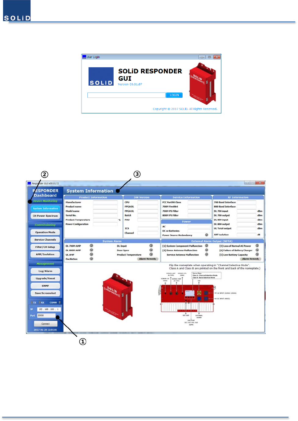
4.2.2 Log in GUI
When you click the Responder GUI icon, the following window will be popped up.
Figure 29. Login Window
To enter the GUI, type the login password that has been delivered.
4.2.3 GUI Main Screen
Below is the layout of the main screen of GUI.
Figure 30. Main Screen of GUI
① Communication: it represents the communication status and the connection information with the device.
② Main Menu: these are categorized in three parts.
A. Device Monitoring: these features are for monitoring the device
B. Commissioning: these features are for setting up the device
C. Management: these features are for device management.
③ Main Window: these features are for checking all the information about the Responder.
User Manual of SRDR-33-7080-A
©2017 SOLiD, Inc. All Rights Reserved. Confidential & Proprietary. Page 47 / 70
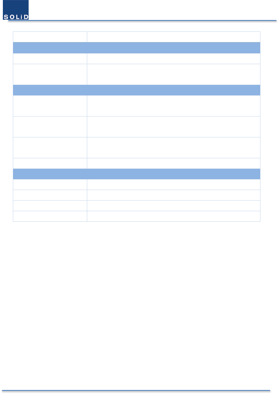
Table 14. Description of Main Menu
Item
Descriptions
Device Monitoring
System Information
It displays current status and alarms of the Responder.
CH Power Spectrum
It displays the information about input/output signals (DL only) and filters
of the Responder in the graphs.
Commissioning
Operation Mode Users can see the operation mode of the Responder
And, It allows users to select a mode to operate the Responder.
Service Channels
It displays frequency information about service channels that are
provided in your area.
Filter / CH Setup It displays information about the filters, channel powers, and gains in the
Responder.
AMP / Isolation
It displays the status of the power amplifier and the antenna isolation.
Management
Log / Alarm
It allows users to set alarms’ condition and to check alarm history as well.
Upgrade / Reset It allows users to update the firmware and to reset the Responder.
SNMP
It allows users to set network parameters and the current time.
Save Screenshot It allows users to capture the current GUI screen image.
User Manual of SRDR-33-7080-A
©2017 SOLiD, Inc. All Rights Reserved. Confidential & Proprietary. Page 48 / 70
4.3 Configuring Operation Mode of the Product
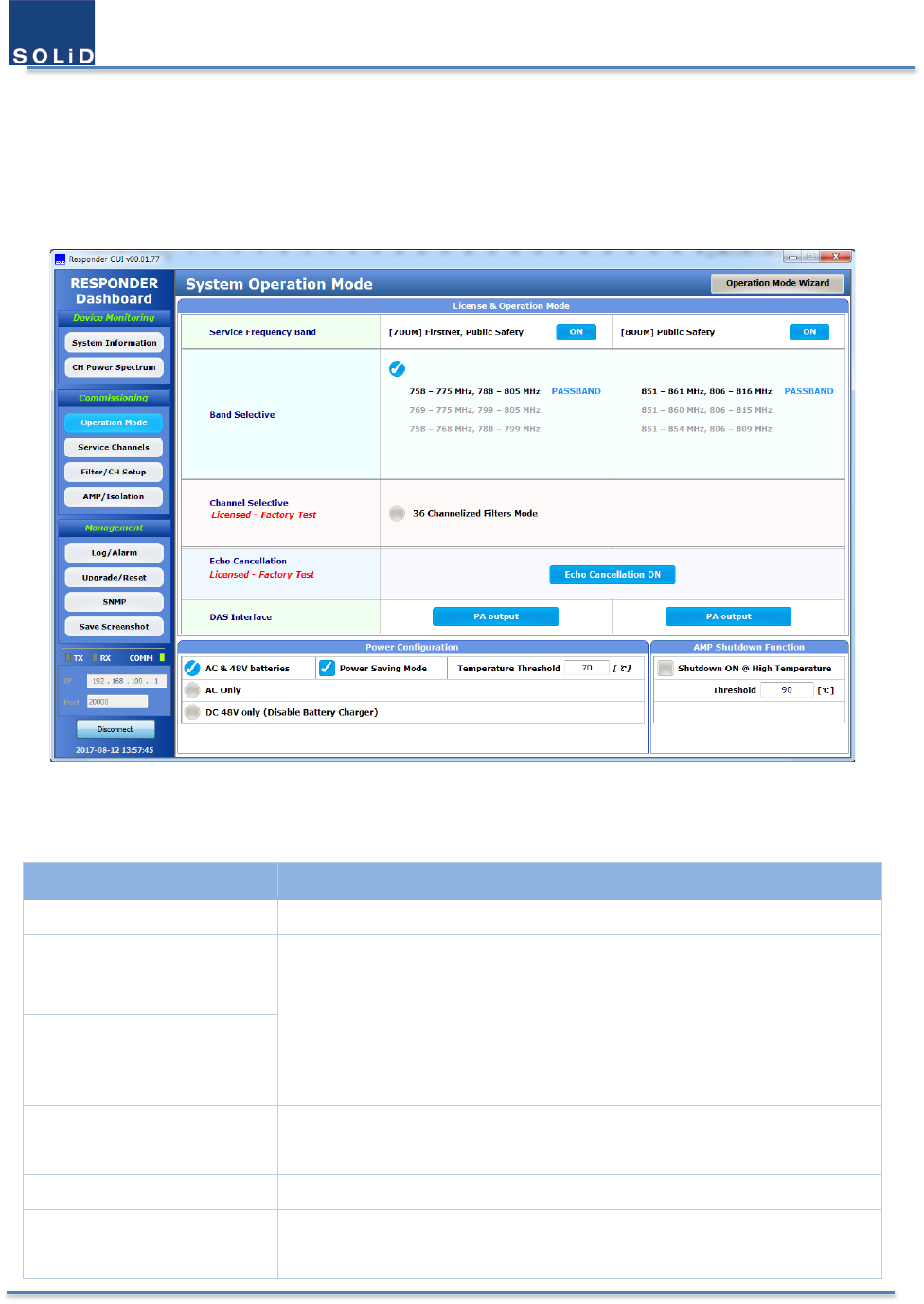
4.3.1 Operation Mode Window
The below Window shows the operation mode that user has selected or factory setting.
Figure 31. System Operation Mode Window
Table 15. Description of Operation Mode Items
Item
Description
Service Frequency Band ON/OFF of 700M/800M Path
Band Selective
The selected option is shown among the 2 options.
① Pre-Configured Filter Mode
② 36 Channelized Filter Mode
The 2nd option can be possible with the Channel license.
The mixed combination of filters across two bands is impossible.
Channel Selective
Echo Cancellation ON/OFF of Echo Cancellation
This feature can be chosen with Echo Cancellation license.
DAS Interface
The downlink output and uplink input port to the service antenna
Power Configuration The power redundancy type for alarms.
and the status of the power-saving mode
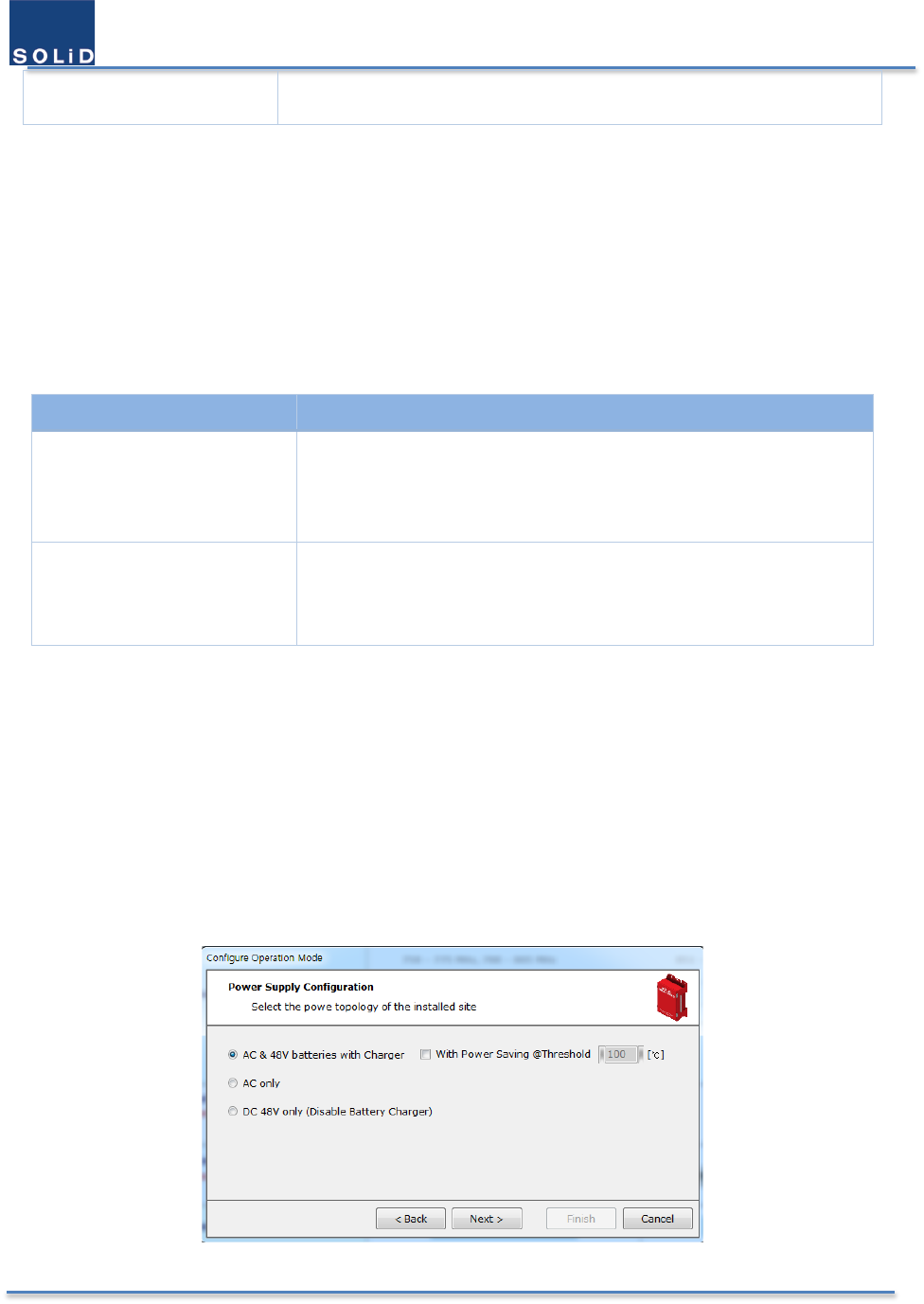
User Manual of SRDR-33-7080-A
©2017 SOLiD, Inc. All Rights Reserved. Confidential & Proprietary. Page 49 / 70
AMP Shutdown The status of Shutdown AMP function at the high temperature.
4.3.2 Changing Operation Mode
To change an operation mode, click the Operation Mode Wizard button in the top of the window. You can’t edit or
modify the setting by clicking directly the main window. The operation mode will be changed after press Finish
button in the popped small window that appears at last stage.
4.3.3 Filter Mode
The Responder supports two types of filters. (Note that you need to have Channel License for using Channelized
Filter Mode.)
Item Description
Band Selective
Pre-Configured Filter Mode
ON/OFF of 700M PS NB and 700M FirstNet
Passband of 800M PS (with 3, 9, and 10 MHz filters)
Channel Selective
(with license)
36 Channelized Filter Mode
up to 36 channel filters for 700M and 800M PS
Any increment is possible across two bands
4.3.4 Echo Cancellation
The Echo Cancellation feature includes an advanced algorithm that allows the repeater to maintain maximum gain
even when system isolation deteriorates to as low as the gain of the repeater. Traditional repeaters require at least
15-20dB more isolation than system gain to prevent oscillation. The “ZeroDelta” feature allows normal operation
with 0dB difference between system isolation and system gain.
4.3.5 Power Supply Configuration
Select a power supply configuration from the list to report alarms properly. When the AC & 48V batteries with
Charger is selected, Power Saving Mode can be chosen.
Figure 32. Power Supply Configuration
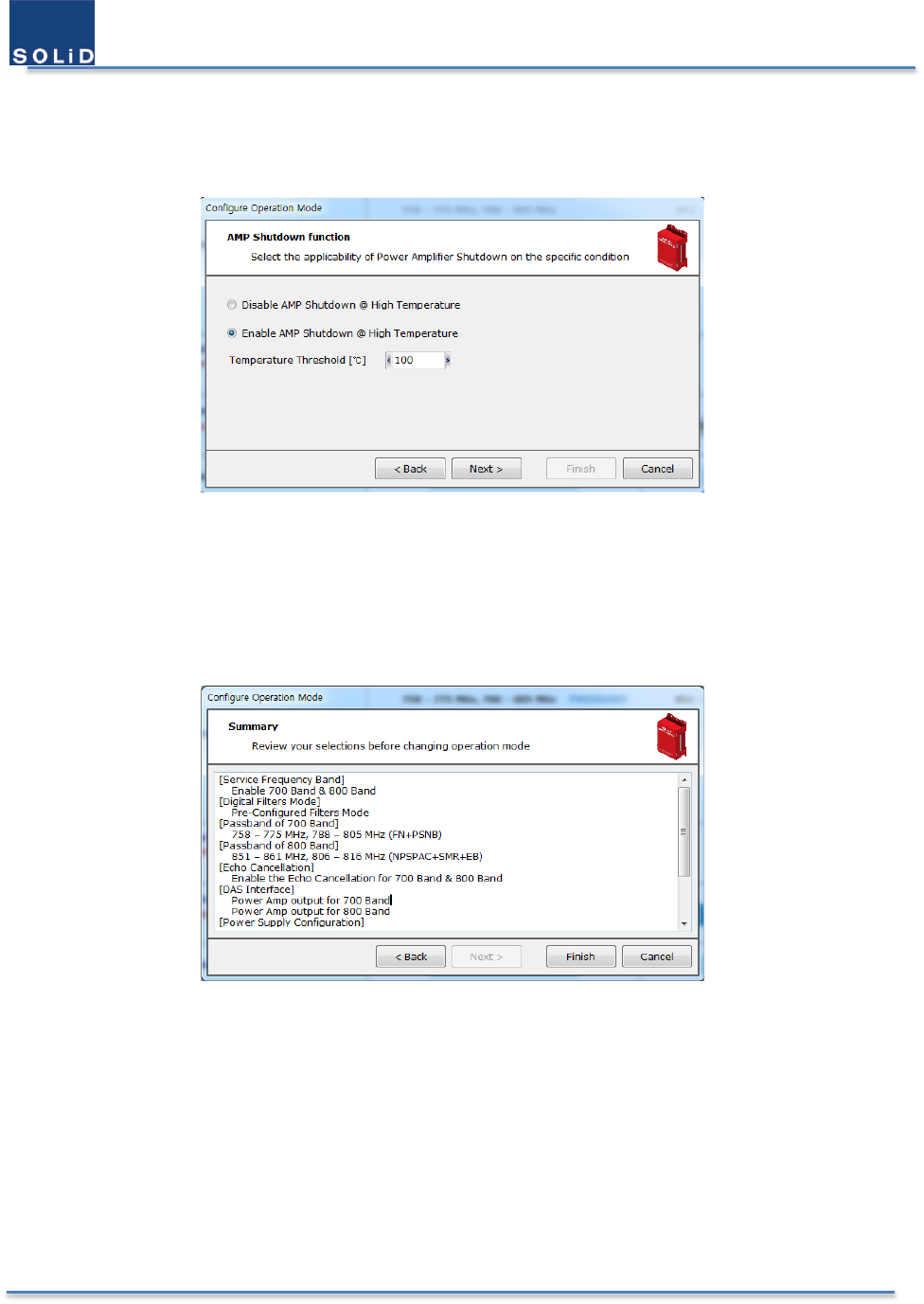
User Manual of SRDR-33-7080-A
©2017 SOLiD, Inc. All Rights Reserved. Confidential & Proprietary. Page 50 / 70
4.3.6 AMP Shutdown function
It allows users to choose whether to shut down the AMP when the temperature reaches the specific level.
Figure 33. AMP Shutdown Function
4.3.7 Summary
At the last stage, you can check all the information of the modes you selected. When you click the Finish button,
those selected modes will be applied to the Responder.
Figure 34. Summary of Selecting the Operation Modes
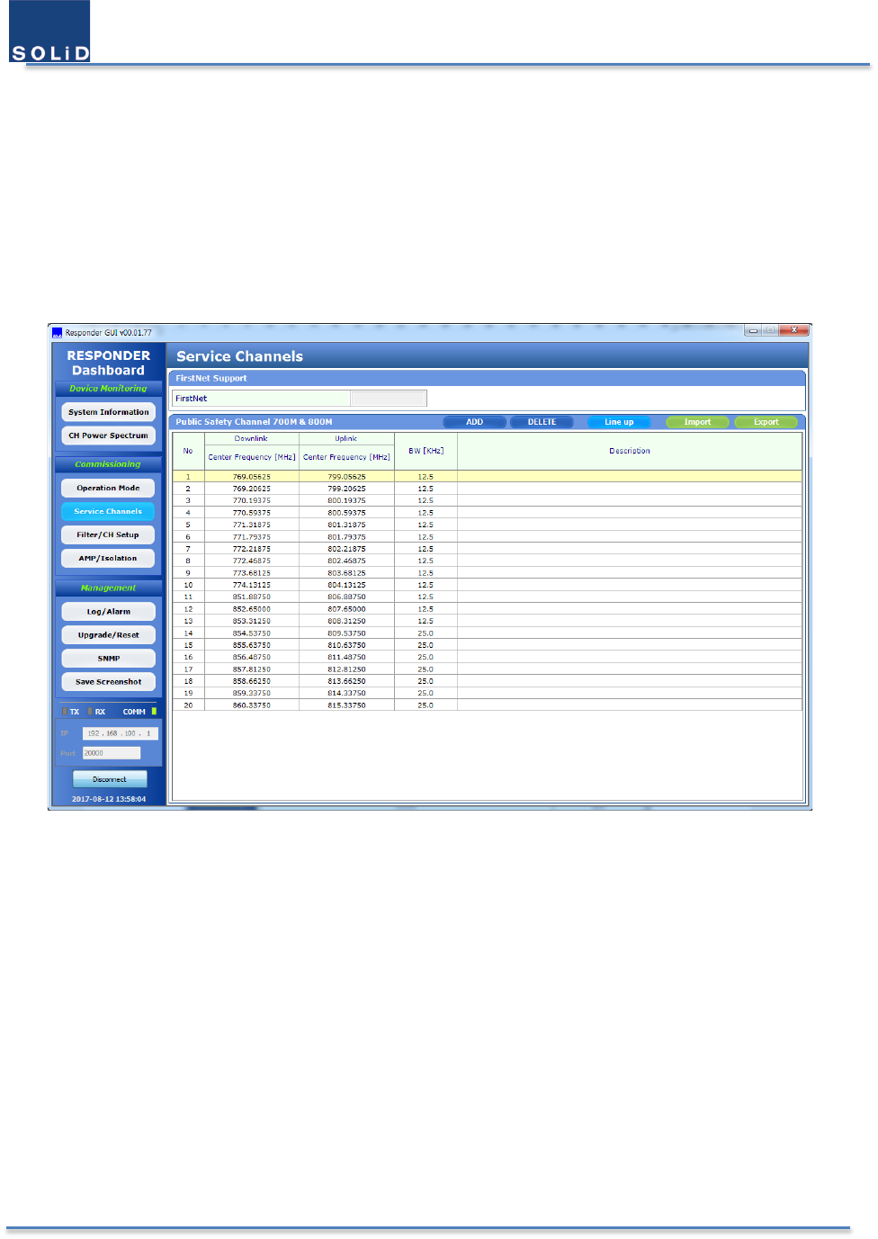
User Manual of SRDR-33-7080-A
©2017 SOLiD, Inc. All Rights Reserved. Confidential & Proprietary. Page 51 / 70
4.4 Setup Channel Configuration & RF parameters
4.4.1 Input the information of service channels
Service Channels are the channels which is used for the public safety purpose in the specific region. These channels
should be passed and amplified in the equipment. And it is, of course, essential for the channel filters. All the
information about the service channels can be imported and be exported with the csv file. Below is the window for
the importing the service channels.
Figure 35. Service Channels Window
4.4.2 Setup Parameters of Digital Filter
4.4.2.1 Pre-Configured Filter Mode
When you select Pre-Configured Filter mode from the Operation Mode, three band-configuration will be displayed
as shown below. In this mode, users can control ON/OFF feature of each band and adjust attenuation values up to
10dB. In the System setting on the bottom, users can set the maximum gain and maximum output power of the
system. The equipment will not exceed these level.
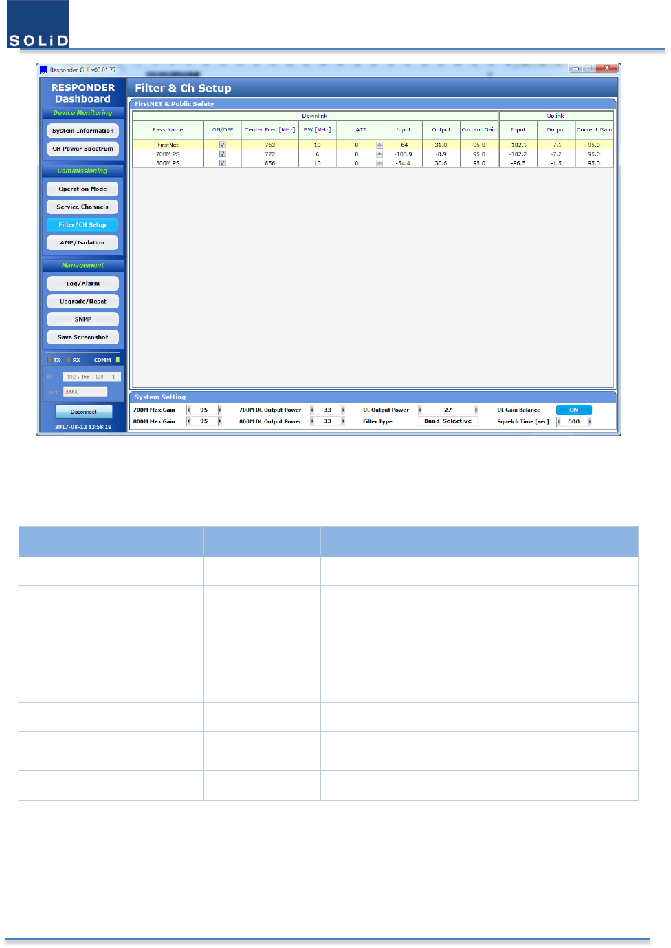
User Manual of SRDR-33-7080-A
©2017 SOLiD, Inc. All Rights Reserved. Confidential & Proprietary. Page 52 / 70
Figure 36. Pre-Configured Filter Mode Window
Table 16. Pre-configured Filter Parameters
Item Range Description
700M Max Gain 65 – 95 dB Set the maximum gain of 700M
800M Max Gain 65 – 95 dB Set the maximum gain of 800M
700M DL Output Power 3 – 33 dBm Set the maximum output of 700M DL
800M DL Output Power 3 – 33 dBm Set the maximum output power of 800M DL
UL Output Power 0 – 27 dBm Set the maximum output power of UL
Filter Type Band/Channel only displayed
UL Gain Balance On/Off UL gain has the same value with DL gain
As a default, gain balance is on.
Squelch Time 1 – 3600 sec Dwell time to detect the Squelch
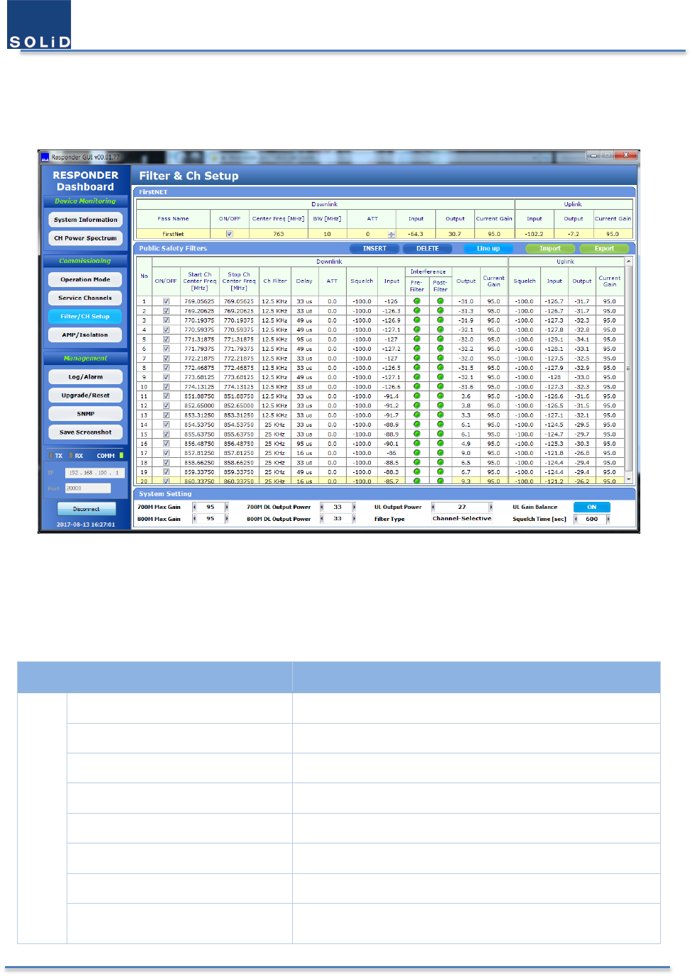
User Manual of SRDR-33-7080-A
©2017 SOLiD, Inc. All Rights Reserved. Confidential & Proprietary. Page 53 / 70
4.4.2.2 36 Channelized Filters
In the 36 Channelized Filter Mode, users can set the total 36 channel-filters across 700M and 800M bands. Users can
Export and Import the information about the current filter.
Figure 37. Channelized Filter Mode Window
Public Safety Filters for the narrowband include the following information.
Table 17. 36 Channelized Filter Parameters
Item Description
DL
Start CH Center Freq. The lowest channel freq. of the passband
Stop CH Center Freq. The highest channel freq. of the passband
CH Filter Bandwidth of filter
Delay Group Delay of filter
ATT Attenuation value
Squelch Squelch level
Input Input power
Interference Pre filter: Interference status before a CH filter
Post Filter: Interference status after a CH filter

User Manual of SRDR-33-7080-A
©2017 SOLiD, Inc. All Rights Reserved. Confidential & Proprietary. Page 54 / 70
Output Output power
Current Gain Current gain
UL
Squelch Squelch level
Input Input power
Output Output power
Current Gain Current gain
The color of circles in the Interference column indicates the relative strength with the channel power. This state is
not real-time, but is updated every 2 minutes.
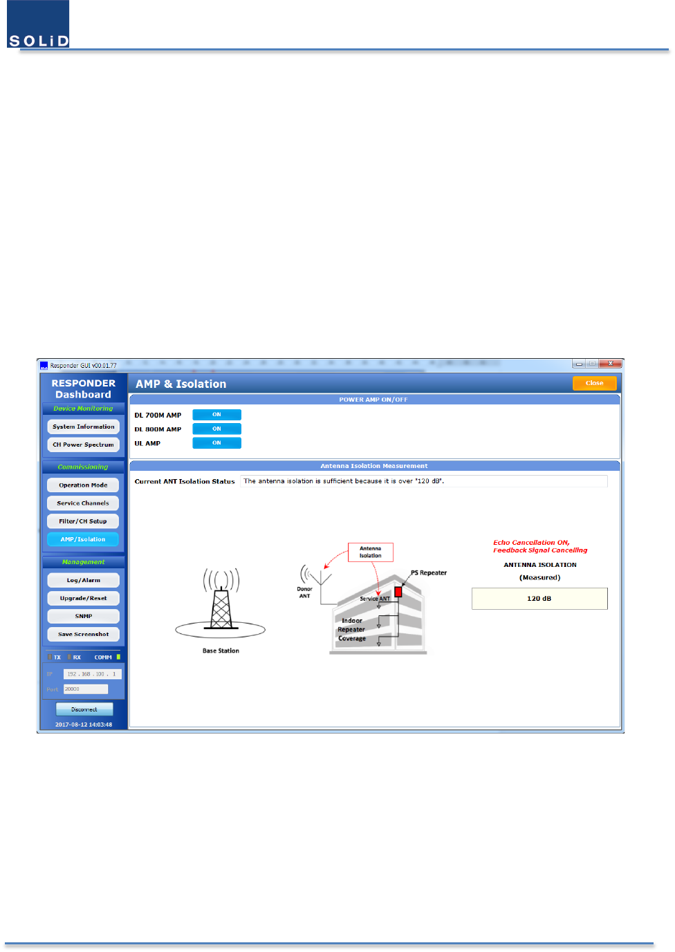
User Manual of SRDR-33-7080-A
©2017 SOLiD, Inc. All Rights Reserved. Confidential & Proprietary. Page 55 / 70
4.5 Isolation Measurement & Tune-up
4.5.1 Monitor Downlink Input Power
Observe downlink input power from the GUI. To receive the input signal with high signal-to-noise ratio is essential
to maintain the service with better condition. Align the direction of donor antenna until the DL input power reading
is maximized.
4.5.2 Measure the isolation between donor antenna and service antenna
SOLiD Responder has the powerful algorithm to measure antenna isolation which doesn’t interfere with radio service.
After finishing the basic connection with both antennas, user just enable the amplifier and wait for the result for a
moment.
Figure 38. Isolation Measurement Window
4.5.3 Evaluate isolation value & reconfigure the antenna installation
BDA oscillation is caused by low isolation (antenna separation) between donor antenna and service antennas. The
recommended isolation between those antennas is 20 dB above the system gain. The amount of isolation that can
be achieved between antennas depends on several factors, such as the physical vertical and horizontal separation
(distance between the antennas), polarization, radiation pattern of the antennas, the medium between the antennas,
antenna gain etc. Considering the above serveral conditions, evaluate the antenna isolation if it is adequate to cover.

User Manual of SRDR-33-7080-A
©2017 SOLiD, Inc. All Rights Reserved. Confidential & Proprietary. Page 56 / 70
4.5.4 Test coverage area
Use test-quipment to verify field intensity within the coverage area. If needed, realign the service antenna to achieve
the desired coverage.
Note that the equipment gain could not be set to maximum or the output power is not high enough due to
insufficient donor and service antennas isolation, then the antennas’ position should be changed to increase
isolation.
4.5.5 Verify UL gain and Performs test calls
Typically, the UL gain is set around 5dB less than DL gain. Users can calculate and determine if the repeater UL noise
will interfere with the BTS. Perform test calls in the coverage area to evaluate voice quality.
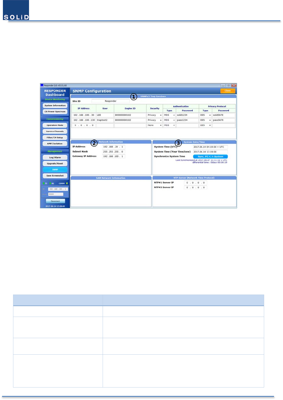
User Manual of SRDR-33-7080-A
©2017 SOLiD, Inc. All Rights Reserved. Confidential & Proprietary. Page 57 / 70
4.6 SNMP traps & Time Settings
The Responder can notify the remote server about the external alarm output through SNMP (Simple Network
Management Protocol) Traps. To use this feature, fill the parameters about network and SNMP traps in the ①
section as shown below.
Figure 39. SNMP Configuration
The Responder has another port that can be connected to the external network as well as a port for GUI. You should
fill the appropriate network parameters in the ② section to connect the Responder to the internet.
The Responder has Real Time Clock(RTC) inside and uses Universal Time Coordinated (UTC). Users can synchronize
Responder’s time with the time of GUI in the PC by clicking Sync.PC System button in the ③ section. Network
Time Protocol (NTP) is a networking protocol for clock synchronization between computer systems over packet-
switched, variable-latency data networks.If you change the time in the ③ section, the time for the alarm message
also changes.
Table 18. Parameters of Time Setting
Item
Description
System Time (UTC) It is the UTC time that the Responder has set as the absolute time.
System Time
(Your Time zone)
Local time:
If you connect your computer with the Responder, the
System Time on the GUI will display the time of your computer.
Sync. PC <-> System It
synchronizes the time of the Responder with currently
connected computer.
NTP#1 & 2 Server IP
Time synchronization can be done and controlled automatically
when the Responder is connected with the external network. To
use this feature, enter the IP address of NTP server that will be
connected.
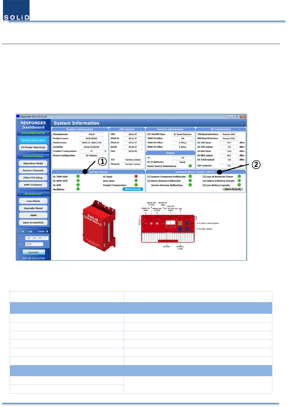
User Manual of SRDR-33-7080-A
©2017 SOLiD, Inc. All Rights Reserved. Confidential & Proprietary. Page 58 / 70
5 Administrations
5.1 Viewing General Information
Since the passband’s ranges of SOLiD RESPONDER are 12.5 – 200 KHz, FCC part 90 Class A or B device is possible in
this mode. If all the passbands are no wider than 75 KHz, the equipment will be Class A device. Otherwise it is Class
B device. User can also check FCC part 90 Class from the System Information window.
Figure 40. System Information Window
Table 19. Description of System Information
Item Description
Product Information
Manufacturer
SOLiD
Product Name
RESPONDER
Model Name
Model information, SRDR-33-7080-A-FN
Serial No.
Serial number of the Responder
Product Temperature
The temperature on the bottom side of the Responder
Power Configuration
Status of power supply
Software Version
CPU
Information regarding software versions
FPGA DL, FPGA UL
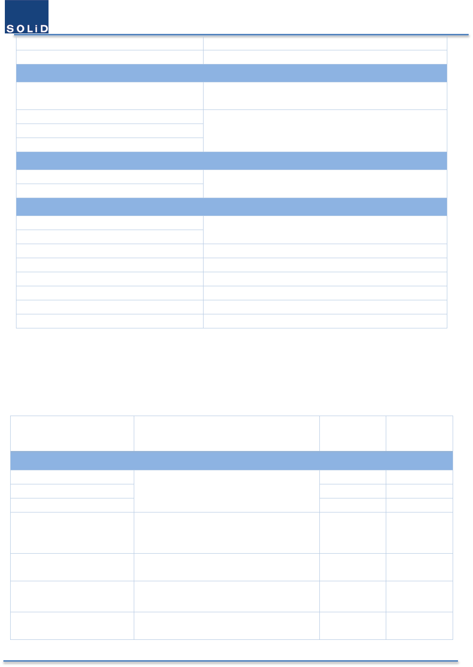
User Manual of SRDR-33-7080-A
©2017 SOLiD, Inc. All Rights Reserved. Confidential & Proprietary. Page 59 / 70
Batch, PAU
ICS, Channel
Information whether a user has the license or not
Service Information
FCC Part 90 Class B/Band-Selective
A/Channel-Selective
700M FirstNet
Filter information that is in service
700M PS Filter
800M PS Filter
Power
AC
Status of power supply
DC or Battery
RF Information
700 Band Interface
Output port to the service antenna
Active DAS or Passive DAS
800 Band Interface
DL 700 Input
DL 700M input power
DL 700 Output
DL 700M output power
DL 800 Input
DL 800M input power
DL 800 Output
DL 800M output power
UL Total Output
UL 700M/800M composite output power
ANT Isolation
Antenna isolation information
5.2 Alarm Remedy
Below is the table that describes the meaning and the condition of alrams.
Table 20. Description of Alarms
Alarm Item Description
Dwell Time
to issue
Dwell Time
to Clear
① System Alarm
DL 700M AMP
ON or OFF status of each AMP
Immediately
Immediately
DL 800M AMP
Immediately
Immediately
UL AMP
Immediately
Immediately
Oscillation If oscillation occurs continuously, the alarm
occurs.
Continuous
oscillations
occur
Otherwise
DL Input
If downlink input power is low, the alarm
occurs.
5 seconds 5 seconds
Door Open When the door opened, the alarm occurs. Immediately Immediately
Product Temperature If the temperature of bottom side is higher
than the threshold level, the alarm occurs.
5 seconds 5 seconds
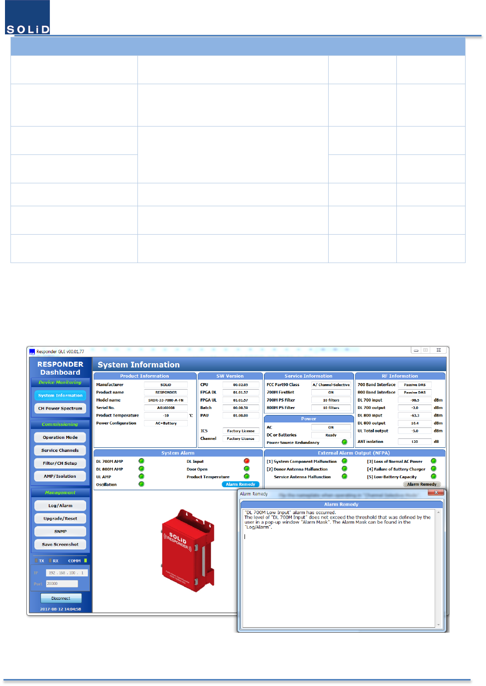
User Manual of SRDR-33-7080-A
©2017 SOLiD, Inc. All Rights Reserved. Confidential & Proprietary. Page 60 / 70
② External Alarm Output (NFPA)
Power Source Redundancy If DC power switch is off for the case of AC
and batteries, the alarm occurs.
5 seconds 5 seconds
System Component
Malfunction
It monitors the device whether it is normal.
(If it detects an abnormality, the alarm
occurs.)
1 minute 1 minute
Donor Antenna
Malfunction
It monitors VSWR status at the port of the
device.
(If there is failure or no antenna, the alarm
occurs.)
5 minutes 1 minute
Service Antenna
Malfunction
5 minutes 1 minute
Loss of Normal AC Power If there is no AC power, the alarm occurs. 1 minute 1 minute
Failure of Battery Charger If there is battery charger failure, the alarm
occurs.
1 minute 1 minute
Low-Battery Capacity If the battery power is below 70%, the alarm
occurs.
1 minute 1 minute
※ Dwell time to issue: the duration for issuing an alarm
※ Dwell time to clear: the duration for clearing an alarm
When an alarm occurs, the Alarm Remedy button is blinking in green. When you click the Alarm Remedy button, you
can see the detailed information about the alarm.
Figure 41. Example of Alarm Remedy
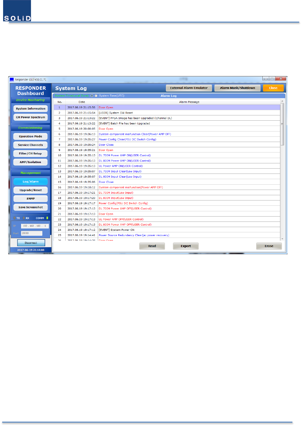
User Manual of SRDR-33-7080-A
©2017 SOLiD, Inc. All Rights Reserved. Confidential & Proprietary. Page 61 / 70
5.3 Alarm Log
5.3.1 Alarm History
Figure 42. System Log
From the above system log, alarms in red mean alarms issued, and alarms in blue mean alarms cleared. Messages in
black mean the user’s actions. The Responder can store up to 400 logs. When a user wants to save alarms logs, click
Export button to save them as files. When a user wants to delete all the logs from the Responder, click Erase button
in the bottom.
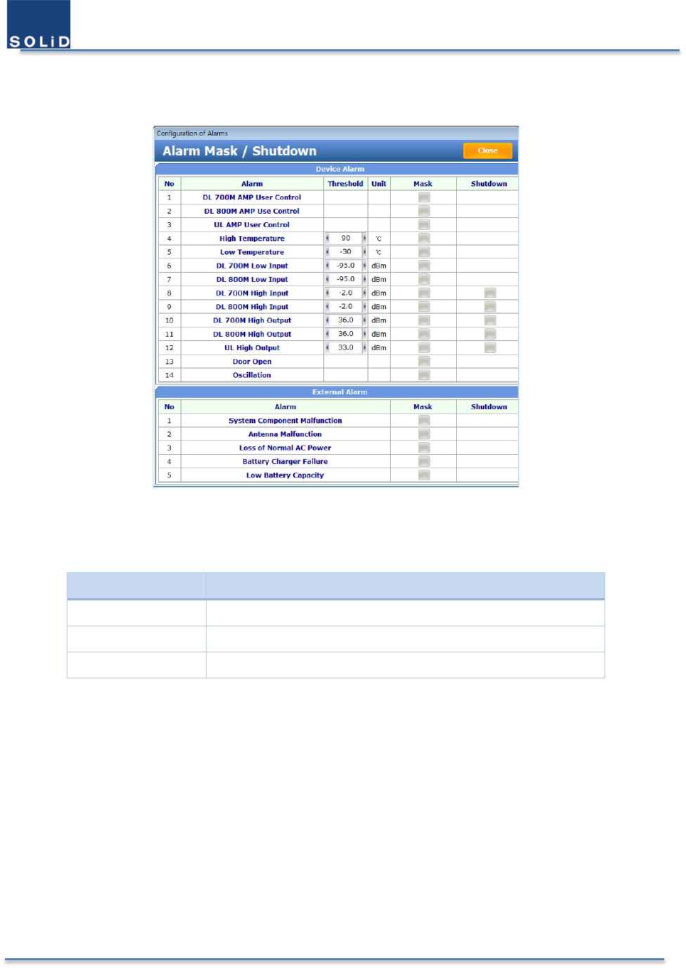
User Manual of SRDR-33-7080-A
©2017 SOLiD, Inc. All Rights Reserved. Confidential & Proprietary. Page 62 / 70
5.3.2 Alarm Mask / Shutdown
Click Alarm Mask / Shutdown button to check or change parameters of alarms as shown below.
Figure 43. Alarm Mask / Shutdown
Table 21. Description of Terms in the Alarm Mask
Item
Description
Threshold If it exceeds the threshold value, the alarm occurs.
Mask Display and change the masking of alarms
Shutdown ON/OFF feature of each condition for Power AMP Auto Shutdown
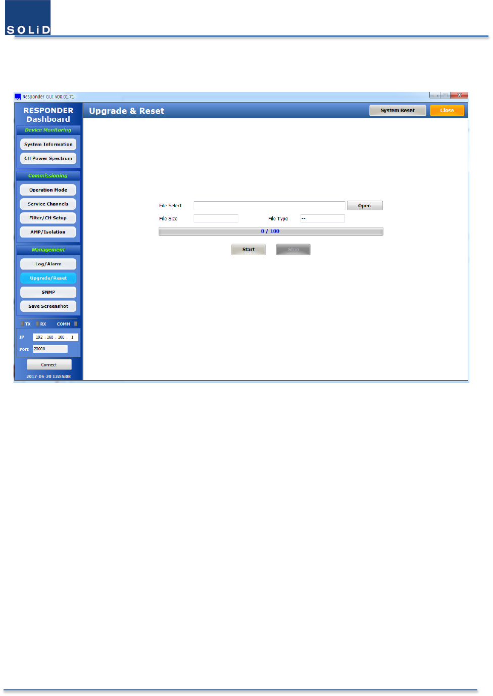
User Manual of SRDR-33-7080-A
©2017 SOLiD, Inc. All Rights Reserved. Confidential & Proprietary. Page 63 / 70
5.4 Firmware Upgrade
It allows users to update firmware or to reset the system.
Figure 44. Upgrade / Reset
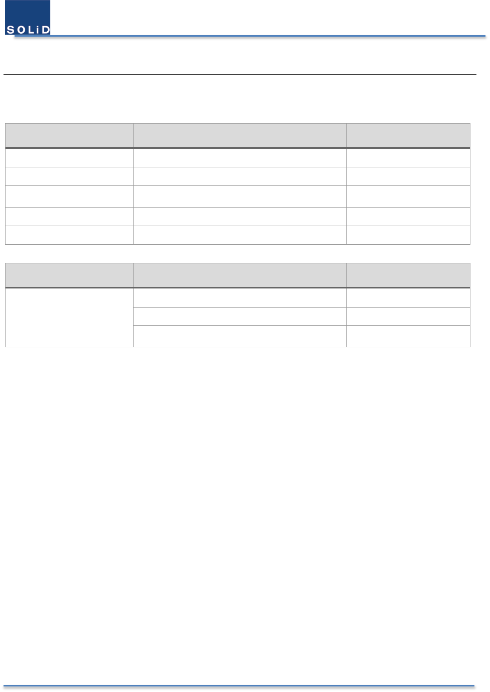
User Manual of SRDR-33-7080-A
©2017 SOLiD, Inc. All Rights Reserved. Confidential & Proprietary. Page 64 / 70
6 Appendix
6.1 Environmental Specification
Item Value Comments
Operating Temperature -30 - 60℃
Cooling
Convection No fan inside
Humidity 10 % - 90% condensed
Enclosure
IP66, NEMA 4
Installation site Indoor & Outdoor
Item Value Comments
Compliance
FCC
UL
NFPA/IFC
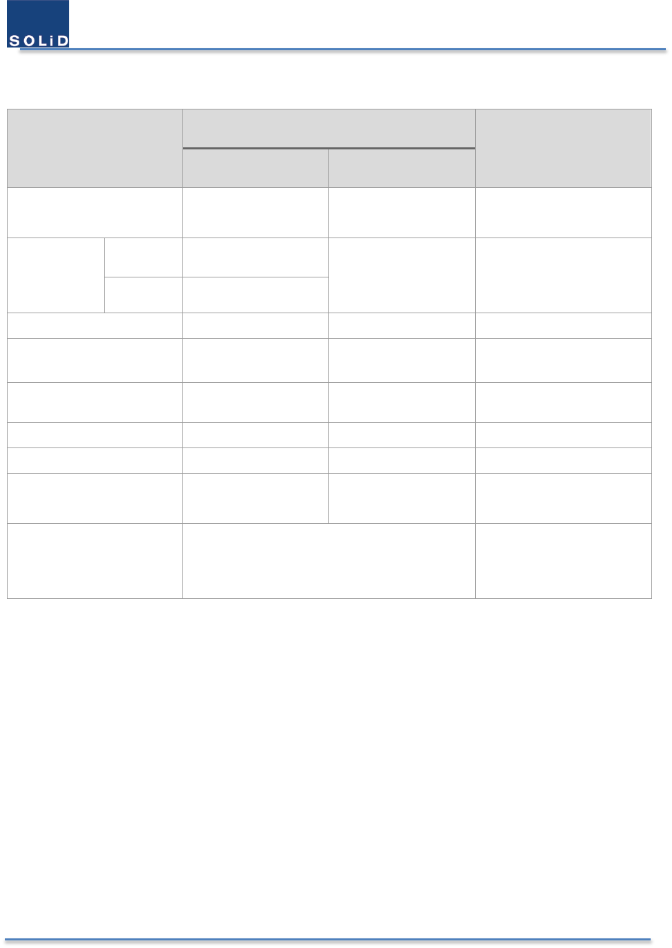
User Manual of SRDR-33-7080-A
©2017 SOLiD, Inc. All Rights Reserved. Confidential & Proprietary. Page 65 / 70
6.2 Radio Frequency Specification
Item
Value
Comments
Downlink Uplink
Frequency Range 758 – 775 MHz
851 – 861 MHz
788 – 805 MHz
806 – 816 MHz
Composite
Output
Power
700 PS +33 dBm (2W) +30 dBm (1W)
composite
800 PS +33 dBm (2W)
Passband Gain
65 – 95 dB 65 – 95 dB Adjustable with 1dB steps
Passband Ripple ±2.5 dB ±2.5 dB
Spurious emission -13 dBm -13 dBm
Noise Figure 6 dB 6 dB
Group Delay
4.5 – 99 usec 4.5 – 99 usec Depends on types of filters
Maximum RF Input
Power with no damage + 10 dBm + 10 dBm
Squelch -110 – -60 dBm
Per channel
for UL & DL
Adjustable with 1dB steps
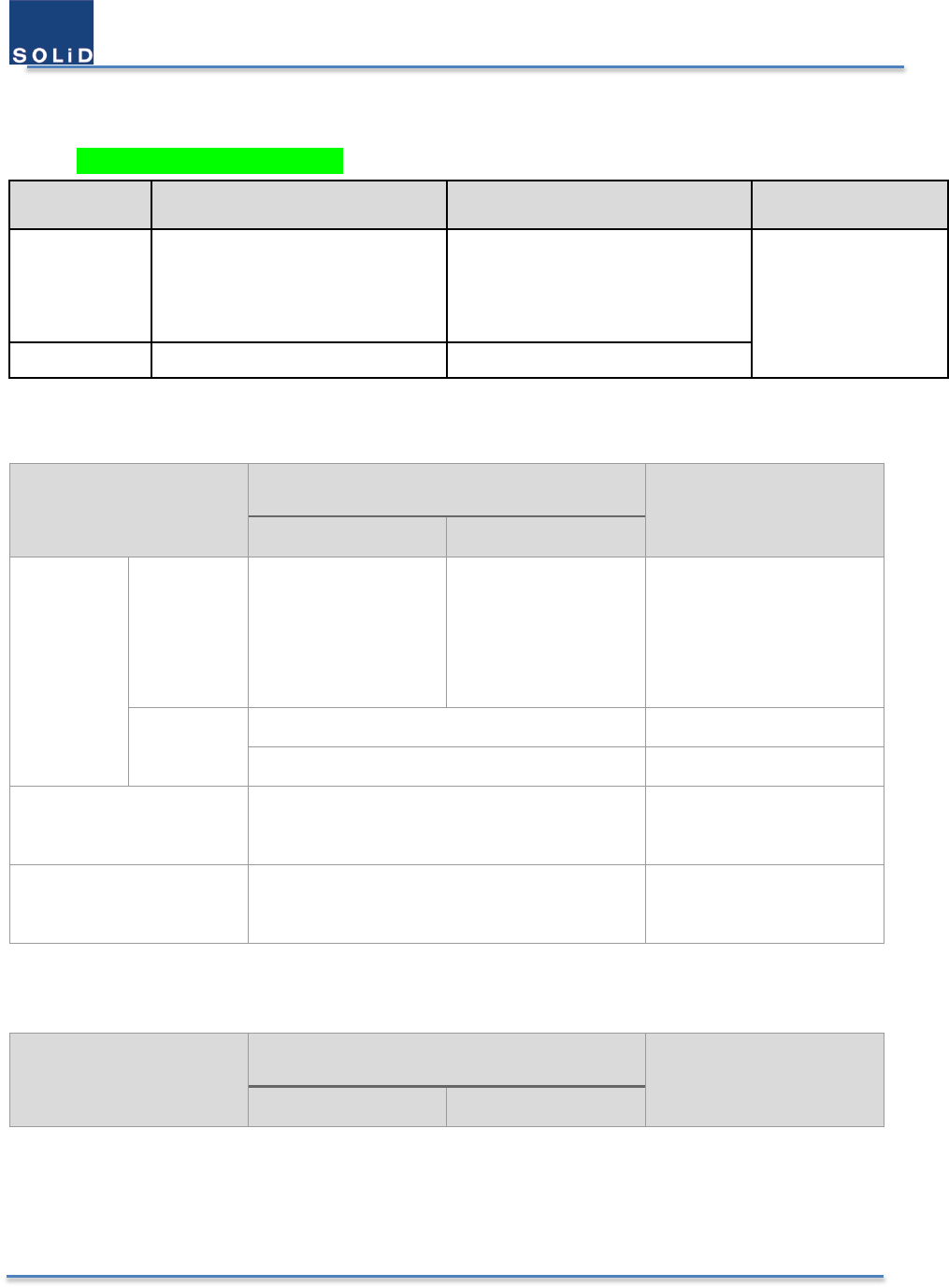
User Manual of SRDR-33-7080-A
©2017 SOLiD, Inc. All Rights Reserved. Confidential & Proprietary. Page 66 / 70
6.3 Digital Filter Specification
• Operating Frequency For B9A
Frequency DL UL Modulation
PS 700
769 - 775MHz(For FCC)
(768-769MHzGuard band)
768 – 775 MHz (For ISED)
799 - 805 MHz(For FCC)
(798- 799MHz Guard band)
798 - 805 MHz (For ISED)
P25
Analog FM (25 kHz)
PS 800 851 - 861 MHz 806 - 816 MHz
6.3.1 Public Safety 700 MHz Band–Selective (Class B)
Item
Band-Selective
Comments
Downlink Uplink
Pre-
configured
Frequency
Range
① 758 – 775 MHz
② 769 – 775 MHz
③ 758 – 768 MHz
① 788 – 805 MHz
② 799 – 805 MHz
③ 788 – 798 MHz
① PS NB + FirstNet
(M71)
② PS NB only (M72)
③ FirstNet only (M73)
Delay
4.5 us for 758 – 768/ 799 – 805 MHz
6 us for 769 – 775 / 788 – 805 MHz
Variable Gain Range
0 – 10 dB with 1dB Step
(attenuation only) For DL & UL
Squelch
Adjustable with 1 dB steps
for -110 – -60 dBm For DL & UL
6.3.2 Public Safety 800 MHz Band –Selective (Class B)
Item
Band-Selective
Comments
Downlink Uplink
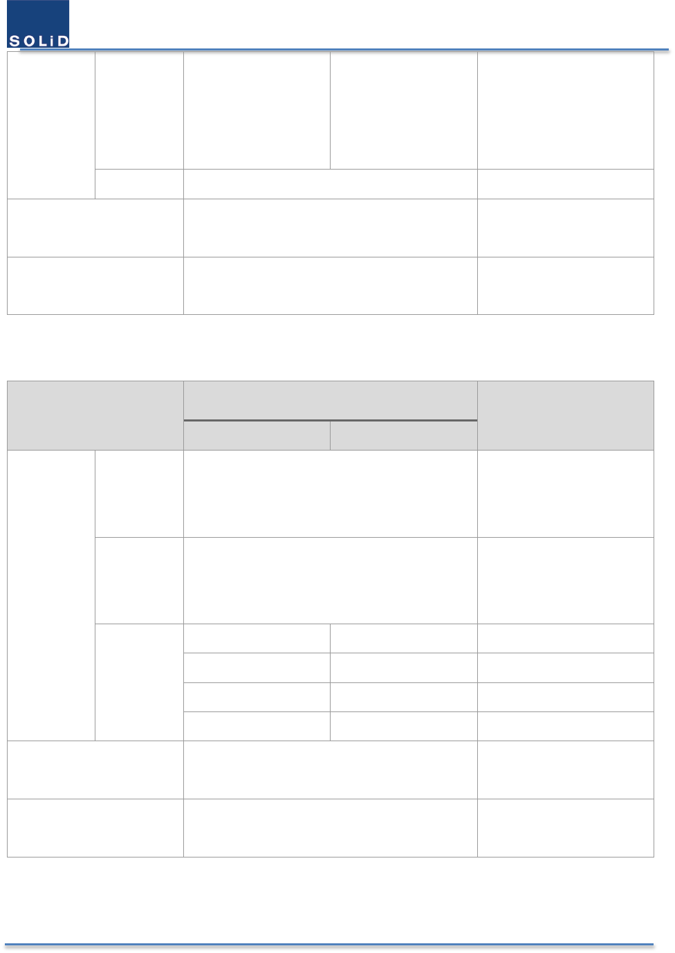
User Manual of SRDR-33-7080-A
©2017 SOLiD, Inc. All Rights Reserved. Confidential & Proprietary. Page 67 / 70
Pre-
configured
Frequency
Range
① 851 – 861 MHz
② 851 – 860 MHz
③ 851 – 854 MHz
① 806 – 816 MHz
② 806 – 815 MHz
③ 806 – 809 MHz
①
NSPSPAC, SMR, EB
(M81)
② NSPSPAC, SMR
(M82)
③ NSPSPAC (M83)
Delay 5.5 us 60dB @ 1 MHz offset
Variable Gain Range
0 – 10 dB with 1dB Steps
(attenuation only) For DL & UL
Squelch
Adjustable with 1 dB steps
for -110 – -60 dBm For DL & UL
6.3.3 Public Safety 700 & 800 MHz Channel–Selective (Class A)
Item
Channel Selective
Comments
Downlink Uplink
Semi-auto
&
Manual
BW of
Channel
Filter
12.5, 25 KHz
Number of
Channel
Filter
36
any increment can be
assigned between 700 &
800 bands
Delay
15 us 15 us 50dB @ 110KHz offset
33 us 33 us 50dB @ 30KHz offset
50 us 50 us 50dB @ 20KHz offset
99 us 99 us 50dB @ 10KHz offset
Variable Gain Range
0 – 10 dB with 1dB Step
(attenuation only)
Per Channel
For DL & UL
Squelch
Adjustable with 1 dB steps
for -110 – -60 dBm
Per Channel
For DL & UL
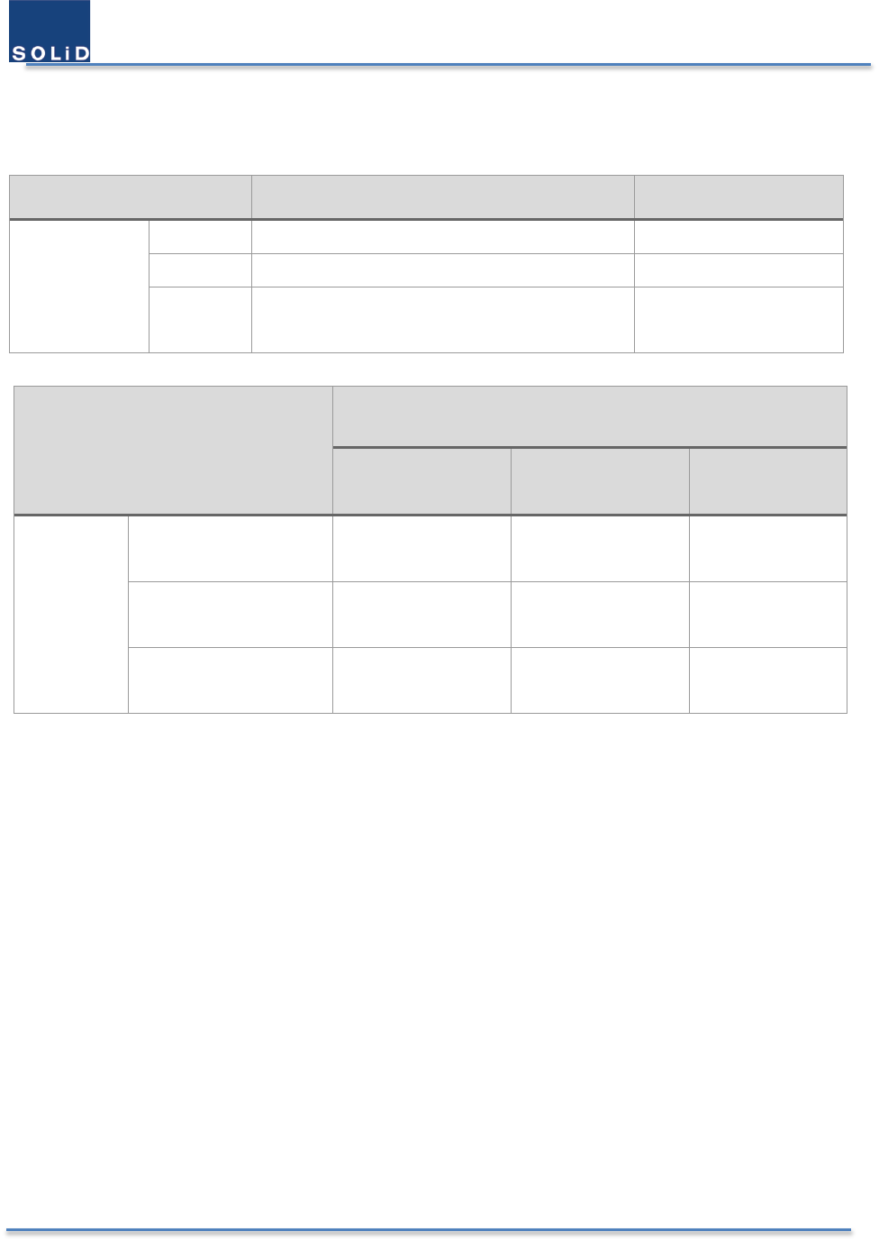
User Manual of SRDR-33-7080-A
©2017 SOLiD, Inc. All Rights Reserved. Confidential & Proprietary. Page 68 / 70
6.4 Power Supply Specification
Item Value Comments
Power
Supply
AC
100 - 120 VAC
DC 48 – 56 VDC
Charger 48V-rail charger for lead-acid batteries
with State of Charge detection Up to 1.7A
Operation Mode
Power Consumption
120 AC 48 VDC Power-Saving
Mode
• 60℃
• Non-
charge
state
Passive DAS
(PS 700 & PS 800) < 165W < 150W < 130W
Passive DAS
(PS 700 or PS 800) < 140 W < 125 W < 110 W
Active DAS Mode
(PS 700 & PS 800) < 110 W < 95 W < 88 W
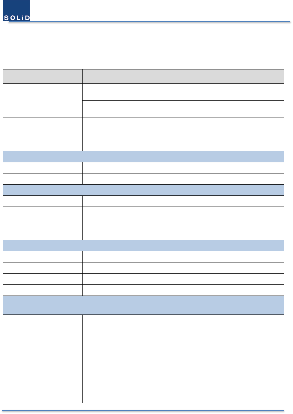
User Manual of SRDR-33-7080-A
©2017 SOLiD, Inc. All Rights Reserved. Confidential & Proprietary. Page 69 / 70
6.5 Mechanical Specification
Item
Value
Comments
Dimensions (HxWxD)
530 x 420 x 208 (mm)
20.9 x 16.5 x 8.2 (inches)
Without bump
630 x 460 x 220 (mm)
24.8 x 18.1 x 9.1 (inches)
With bump
Volume 12.5 gal Without bump
Weight 34kg, 75 lb
19” Rack Mount Yes
Power Port
AC Power
MS3102 16-10S (3pin)
DC Power MS3102 18-10S (2pin)
Antenna Port
Donor N-Female
Donor Coupling SMA-Female 30 dB coupled to antenna port
Service N-Female
Service Coupling
SMA-Female 30 dB coupled to antenna port
Active DAS Port
700 DL QMA, Female -5dBm @ maximum
800 DL QMA, Female -5dBm @ maximum
700 UL QMA, Female
800 UL QMA, Female
Communications Port
Antenna Port – WiFi SMA, Female Local management terminal
Ethernet Port RJ-45 port with IP66 SNMP traps
Relay Output MS3102 20-29S (17 pin)
5 Relay outputs
① System component malfunction.
② VSWR-antenna malfunction
③ Normal AC power, Loss of
normal AC power

User Manual of SRDR-33-7080-A
©2017 SOLiD, Inc. All Rights Reserved. Confidential & Proprietary. Page 70 / 70
④
Battery charger failure
⑤ Low battery capacity (to 70
percent depletion)
– End of the document –