SORIN CRM CRTDSONR9770 Implantable cardioverter defibrillator User Manual TABLE OF CONTENTS
SORIN CRM Implantable cardioverter defibrillator TABLE OF CONTENTS
UserManual.wiki
>
SORIN CRM
>
CRTDSONR9770 User Manual
Users Manual
Navigation menu
Upload a User Manual
Namespaces
Wiki Guide
HTML
PDF
Info
Views
User Manual
Discussion / Help
Navigation
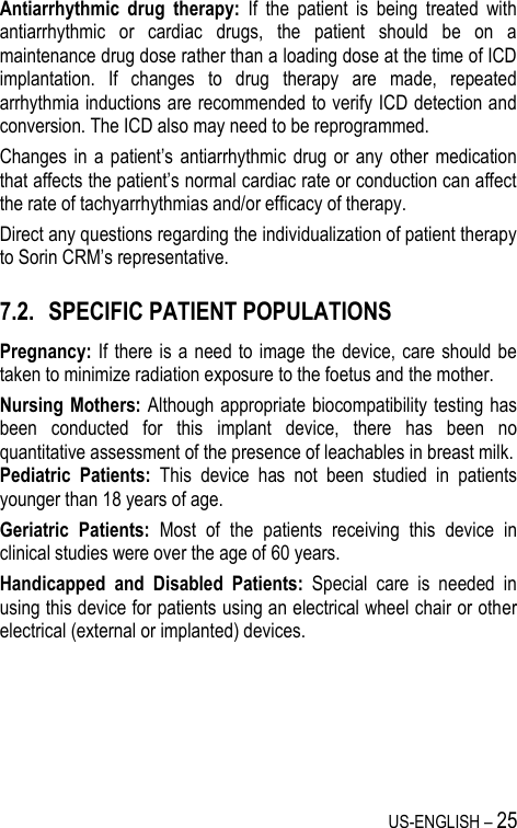
![8 – US-ENGLISH CAUTION: Do not tap sharply on the ICD can after implant, because the ICD's sensing circuits can detect this as P-waves or R-waves, and such oversensing could result in inappropriate pacing, inhibition, or therapy. Normal activities after implant do not result in such oversensing. 4.1. RISKS RELATED TO MEDICAL ENVIRONMENT It is advisable to carefully monitor defibrillator operation prior to and after any medical treatment during which an electrical current from an external source passes through the patient's body. Magnetic Resonance Imaging: MRI is strictly contraindicated in cardiac defibrillator patients. Radiofrequency ablation: A radio frequency ablation procedure in a patient with a generator may cause device malfunction or damage. RF ablation risks may be minimized by: 1. Programming Shock Therapy and ATP to OFF. 2. Avoiding direct contact between the ablation catheter and the implanted lead or generator. 3. Positioning the ground, placing it so that the current pathway does not pass through or near the device, i.e. place the ground plate under the patient’s buttocks or legs. 4. Having external defibrillation equipment available. Electrocautery or diathermy device: Diathermy and electrocautery equipment should not be used. If such devices must be used: 1. Keep the current path and ground plate as far away from the device and the leads as possible (a minimum of 15 cm [six inches]). 2. Before procedure, deactivate ATP and shock therapies. 3. During the procedure, keep the electrocautery device as far as possible from the cardiac defibrillator. Set it at minimum intensity. Use it briefly. 4. After the procedure, check for proper implant function. The device should never be exposed directly to the diathermy source.](https://usermanual.wiki/SORIN-CRM/CRTDSONR9770/User-Guide-1735478-Page-8.png)
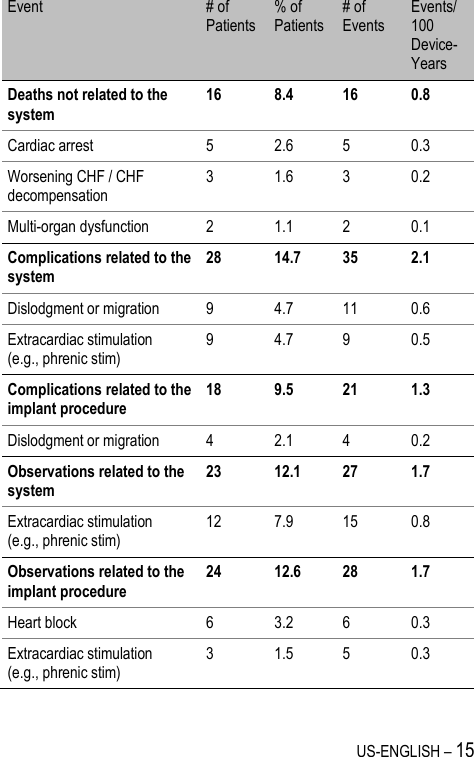

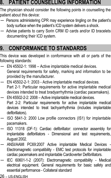


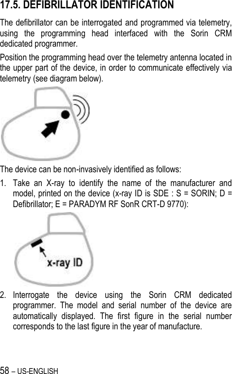

![86 – US-ENGLISH Lead Alerts Values Abnormal A lead impedance ON-OFF Abnormal A lead low limit (Ohm) 200-250-300-350-400-450-500 Abnormal A lead high limit (Ohm) 1500-1750-2000-2500-3000 Abnormal RV lead impedance ON-OFF Abnormal RV lead low limit (Ohm) 200-250-300-350-400-450-500 Abnormal RV lead high limit (Ohm) 1500-1750-2000-2500-3000 Abnormal LV lead impedance ON-OFF Abnormal LV lead low limit (Ohm) 200-250-300-350-400-450-500 Abnormal LV lead high limit (Ohm) 1500-1750-2000-2500-3000 Abnormal RV coil impedance ON-OFF Abnormal SVC coil impedance ON-OFF Abnormal Shock impedance (1) ON-OFF (1) Normal impedance range [20 Ohm-200 Ohm] Clinical status Values V oversensing ON-OFF High AT/AF burden ON-OFF AT/AF limit (on 24h) (h) 0.5-1-3-6-12-24 Fast V Rate during AT/AF ON-OFF Fast V Rate limit (min-1) 80-90-100-110-120 Fast V Duration limit (h) 0.5-1-3-6-12-24 Limited % of V pacing in CRT ON-OFF Limited % of V pacing (%) 50-70-80-85-90-95](https://usermanual.wiki/SORIN-CRM/CRTDSONR9770/User-Guide-1735478-Page-86.png)