SORIN CRM CRTDSONR9770 Implantable cardioverter defibrillator User Manual TABLE OF CONTENTS
SORIN CRM Implantable cardioverter defibrillator TABLE OF CONTENTS
Users Manual
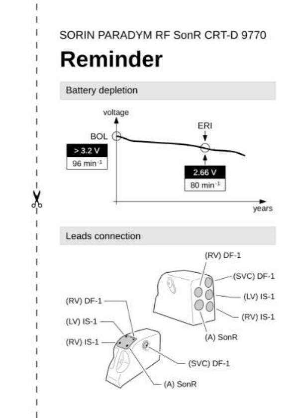

TABLE OF CONTENTS
1. General description ............................................................... 5
2. Indications .............................................................................. 5
3. Contraindications ................................................................... 6
4. Warnings and precautions .................................................... 6
4.1. Risks related to medical environment ................................. 8
4.2. Sterilization, storage and handling .................................... 10
4.3. Implantation and device programming .............................. 10
4.4. Lead evaluation and lead connection ................................ 12
4.5. Generator explant and disposal ......................................... 13
5. Adverse events ..................................................................... 14
5.1. MSP study ............................................................................. 14
5.2. Potential adverse events ..................................................... 16
6. Clinical studies ..................................................................... 18
6.1. MSP clinical study ................................................................ 18
7. Patient selection and treatment .......................................... 24
7.1. Individualization of treatment ............................................. 24
7.2. Specific patient populations ............................................... 25
8. Patient counselling information ......................................... 26
9. Conformance to standards ................................................. 26
10. Physician guidelines ............................................................ 30
10.1. Physician training ................................................................ 30
10.2. Directions for use ................................................................. 31
10.3. Maintaining device quality .................................................. 31
11. Patient information .............................................................. 32
12. How supplied ........................................................................ 32
12.1. Sterility .................................................................................. 32
12.2. Warranty and replacement policy....................................... 32
13. Device description ............................................................... 32
14. Implant procedure ................................................................ 35

14.1. Necessary equipment .......................................................... 35
14.2. Packaging ............................................................................. 36
14.3. Optional equipment ............................................................. 36
14.4. Before opening the package ............................................... 37
14.5. Prior to implantation ............................................................ 37
14.6. Device placement ................................................................. 38
14.7. Choosing the type of lead ................................................... 38
14.8. Measurement of thresholds at implant .................................. 39
14.9. Lead connection ................................................................... 40
14.10. Device implantation ............................................................. 41
14.11. Tests and programming ...................................................... 42
15. Special modes ...................................................................... 42
15.1. Safety mode (nominal values) ............................................ 42
15.2. Magnet mode ........................................................................ 42
15.3. Response in the presence of interference ........................ 43
15.4. Detection characteristics in the presence of
electromagnetic fields ......................................................... 44
15.5. Protection against short-circuits ........................................ 44
16. Main functions ...................................................................... 45
16.1. Automatic lead measurements ........................................... 45
16.2. Atrial tachyarrhythmia management .................................. 45
16.3. Ventricular tachyarrhythmia management ........................ 45
16.4. Pacing.................................................................................... 46
16.5. Sensing ................................................................................. 46
16.6. SonR CRT Optimisation ...................................................... 48
16.7. Follow-up function ............................................................... 49
16.8. Remote monitoring function ............................................... 50
17. Patient follow-up .................................................................. 54
17.1. Follow-up recommendations .............................................. 54
17.2. Holter Function ..................................................................... 55
17.3. Elective Replacement Indicator (ERI) ................................ 56
17.4. Explantation .......................................................................... 57
17.5. Defibrillator identification .................................................... 58
18. Supplemental Information ................................................... 59

18.1. Adverse events in the safer study ...................................... 60
18.2. Safer Clinical study .............................................................. 63
19. Physical characteristics ...................................................... 66
19.1. Materials used ...................................................................... 66
20. Electrical characteristics ..................................................... 67
20.1. Table of delivered shock energy and voltage ................... 68
20.2. Battery ................................................................................... 69
20.3. Longevity .............................................................................. 69
21. Programmable parameters .................................................. 71
21.1. Antibradycardia pacing ....................................................... 71
21.2. Ventricular tachyarrhythmia detection .............................. 77
21.3. Ventricular tachyarrhythmia therapies .............................. 79
21.4. Remote Alerts and warnings............................................... 85
22. Non programmable parameters .......................................... 88
23. Limited Warranty .................................................................. 89
23.1. Article 1: Terms of limited warranty ................................... 90
23.2. Article 2: Terms of replacement ......................................... 92
24. Patents .................................................................................. 93
25. Explanation of symbols ....................................................... 94

US-ENGLISH – 5
1. GENERAL DESCRIPTION
PARADYM RF SonR CRT-D 9770 is an implantable cardioverter
defibrillator for the recognition and treatment of ventricular
tachycardia and fibrillation, with ventricular resynchronization, in
patients with spontaneous or inducible tachyarrhythmias. PARADYM
RF SonR CRT-D 9770 is equipped with an accelerometer to allow
adaptation of pacing to suit the patient’s activity.
PARADYM RF SonR CRT-D 9770 provides high energy shocks
(42 J) for enhanced safety, as well as automatic lead measurements
to monitor system integrity.
PARADYM RF SonR CRT-D 9770 is protected against high-
frequency signals emitted by cellular telephones.
2. INDICATIONS
PARADYM RF SonR CRT-D 9770 is indicated for ventricular
antitachycardia pacing and ventricular defibrillation for automated
treatment of life threatening arrhythmias.
The device is also indicated for the reduction of heart failure
symptoms in medically optimized NYHA Functional Class III and IV
patients with left ventricular ejection fraction of 35% or less, and a
QRS duration of 150 ms or longer.

6 – US-ENGLISH
3. CONTRAINDICATIONS
Implantation of PARADYM RF SonR CRT-D 9770 is contraindicated in
patients:
─ whose ventricular tachyarrhythmias may have transient or
reversible causes such as: acute myocardial infarction, digitalis
intoxication, drowning, electrocution, electrolyte imbalance,
hypoxia, sepsis, or unstable ischemic episodes,
─ who present incessant tachyarrhythmia,
─ who have an internal pacemaker,
─ whose primary disorder is bradyarrhythmias, or atrial tachyarrhythmias.
Dual-chamber and single chamber atrial pacing is contraindicated in
patients with chronic refractory atrial tachyarrhythmias.
4. WARNINGS AND PRECAUTIONS
The patient should be warned of the potential risks of defibrillator
malfunction if he is exposed to external magnetic, electrical, or
electromagnetic signals.
These potential interference sources may cause conversion to
inhibited mode (because of noise detection), erratic delivery of VT or
VF therapies, nominal programming, or much more rarely,
irreversible damage to the device’s circuits.
The main sources of high magnitude electrical interference are:
powerful radiofrequency equipment (radar), industrial motors and
transformers, induction furnaces, resistance and arc-welding
equipment, and high power loudspeakers.
Be aware that the changes in the patient’s condition, drug regimen,
and other factors may change the defibrillation threshold (DFT) which
may result in non-conversion of the arrhythmia post-operatively.
Successful conversion of ventricular fibrillation or ventricular
tachycardia during arrhythmia conversion testing is no assurance
that conversion will occur post-operatively.

US-ENGLISH – 7
Resuscitation Availability: Do not perform device testing unless an
external defibrillator and medical personnel skilled in
cardiopulmonary resuscitation (CPR) are readily available.
Electrical Isolation: Do not permit the patient to contact grounded
equipment that could produce hazardous leakage current. Ensuing
arrhythmia induction could result in the patient’s death.
Disable the ICD During Handling: Program Shock Therapy to OFF
during surgical implant and explant or post mortem procedures.
The device can deliver a serious high energy shock should
accidental contact be made with the defibrillation electrodes.
Antitheft gates: Since antitheft devices at the entrance to stores are
not subject to any safety standards, it is advisable to spend as little
time as possible in their vicinity.
Airport detection systems: Since airport detection systems are not
subject to any safety standards, it is advisable to spend as little time
as possible in their vicinity.
High voltage power transmission lines: High voltage power
transmission lines may generate enough EMI to interfere with
defibrillator operation if approached too closely.
Communication equipment: Communication equipment such as
microwave transmitters, linear power amplifiers, or high-power
amateur transmitters may generate enough EMI to interfere with
defibrillator operation if approached too closely.
Home appliances: Home appliances that are in good working order
and properly grounded do not usually produce enough EMI to
interfere with defibrillator operation. There are reports of device
disturbances caused by electric hand tools or electric razors used
directly over the device implant site.

8 – US-ENGLISH
CAUTION: Do not tap sharply on the ICD can after implant, because the
ICD's sensing circuits can detect this as P-waves or R-waves, and such
oversensing could result in inappropriate pacing, inhibition, or therapy.
Normal activities after implant do not result in such oversensing.
4.1. RISKS RELATED TO MEDICAL ENVIRONMENT
It is advisable to carefully monitor defibrillator operation prior to and
after any medical treatment during which an electrical current from an
external source passes through the patient's body.
Magnetic Resonance Imaging: MRI is strictly contraindicated in
cardiac defibrillator patients.
Radiofrequency ablation: A radio frequency ablation procedure in a
patient with a generator may cause device malfunction or damage.
RF ablation risks may be minimized by: 1. Programming Shock
Therapy and ATP to OFF. 2. Avoiding direct contact between the
ablation catheter and the implanted lead or generator. 3. Positioning
the ground, placing it so that the current pathway does not pass
through or near the device, i.e. place the ground plate under the
patient’s buttocks or legs. 4. Having external defibrillation equipment
available.
Electrocautery or diathermy device: Diathermy and electrocautery
equipment should not be used. If such devices must be used:
1. Keep the current path and ground plate as far away from the
device and the leads as possible (a minimum of 15 cm [six inches]).
2. Before procedure, deactivate ATP and shock therapies. 3. During
the procedure, keep the electrocautery device as far as possible from
the cardiac defibrillator. Set it at minimum intensity. Use it briefly.
4. After the procedure, check for proper implant function. The device
should never be exposed directly to the diathermy source.

US-ENGLISH – 9
External defibrillation: PARADYM RF SonR CRT-D 9770 is
protected from external defibrillation shocks. Before external
defibrillation, deactivate ATP and shock therapies. During external
defibrillation, it is advisable to avoid placing the defibrillating paddles
directly over the casing or over the leads. The defibrillating paddles
should preferably be placed in an anteroposterior position. Avoid any
direct contact between the defibrillation paddles and the conductive
parts of the implanted leads or casing of the implanted device. After
external defibrillation, check for proper device function.
Radiation therapy: Avoid exposure to ionizing radiation. Betatrons
are contraindicated. If high doses of radiation therapy cannot be
avoided, the defibrillator should be protected from direct exposure
with a screen. ATP and shock therapies should be disabled during
exposure and proper device function should be checked regularly
afterwards. Resulting damage may not be immediately detectable.
If irradiation of tissues close to the implantation site is necessary, it is
recommended that the cardiac defibrillator be moved. As a safety
measure, an external defibrillator should be immediately available.
Lithotripsy: Lithotripsy may permanently damage the device if it is at
the focal point of the lithotripsy beam. If lithotripsy must be used,
keep the defibrillator at least 2.5 to 5 cm (1-2 inches) away from the
focal point of the lithotripsy beam.
Diagnostic ultrasound (echography): The defibrillator is not
affected by ultrasound imaging devices.
Scales with body fat monitors and electronic muscle stimulators:
A patient with an implanted PARADYM RF SonR CRT-D 9770 should not
use these devices.

10 – US-ENGLISH
4.2. STERILIZATION, STORAGE AND HANDLING
Resterilization: Do not resterilize and re-implant explanted ICDs.
"Use Before" Date: A "Use Before" date is printed on the outer
storage package and on the sterile package. Do not implant the
device after this date because the battery may have reduced longevity
and sterility may be affected. It should be returned to Sorin CRM.
If Package is damaged: Do not use the device or accessories if the
packaging is wet, punctured, opened or damaged because the
integrity of the sterile packaging may be compromised. Return the
device to the manufacturer.
Device Storage: Store the device in a clean area, away from magnets,
kits containing magnets, and sources of electromagnetic interference to
avoid device damage. Store the device between 0 - 50°C (32 - 122°F).
Temperatures outside the specified range may damage the device.
Equilibration: Allow the device to reach room temperature before
programming or implanting the device because rapid temperature
changes may affect initial device function.
4.3. IMPLANTATION AND DEVICE PROGRAMMING
Use only a Sorin CRM programmer to communicate with the device.
Do not inadvertently position any magnet over the ICD; this suspends
tachyarrhythmia detection and treatment.
Replace the device when the programmer displays an ERI (defined
by a battery voltage of 2.66 ± 0.01 V or a magnet rate lower than or
equal to 80 bpm).
Program device parameters such as sensitivity threshold and VT and
VF detection intervals as specified in the device manuals.

US-ENGLISH – 11
Lead System: Do not use a lead system other than those with
demonstrated compatibility because undersensing cardiac activity
and failure to deliver necessary therapy may result.
In situations where an ICD and a pacemaker are implanted in the
same patient, interaction testing should be completed. If the
interaction between the ICD and the pacemaker cannot be resolved
through repositioning of the leads or reprogramming of either the
pacemaker or the ICD, the pacemaker should not be implanted (or
should be explanted if previously implanted).
Failure to properly insert the torque screwdriver into the perforation at
an angle perpendicular to the connector receptacle may result in
damage to the sealing system and its self-sealing properties.
It is recommended that a security margin of at least 10 J be
demonstrated between the effective shock energy and maximum
programmable energy. Carefully confirm that true ventricular
fibrillation has been induced because the DFT for ventricular
tachycardia or flutter may be lower.
The defibrillator should be implanted with the engraved side facing
outwards in order to facilitate telemetric communication with the
programming head and to display the radiographic identification correctly.

12 – US-ENGLISH
4.4. LEAD EVALUATION AND LEAD CONNECTION
PARADYM RF SonR CRT-D 9770 has two DF-1, two IS-1 connector,
and one sonR connector ports. The sonR connector port has been
specifically designed by Sorin CRM to accept three connections (tripolar).
The two distal connections respect the same dimensions as the IS-1
standard, and an additional proximal connection allows to connect the
sonR signal.
The sonR port accepts either a conventional atrial lead (without sonR
capability) or a sonR atrial lead (bipolar pacing/sensing and sonR
capability). IS-1 refers to the international standard whereby leads and
generators from different manufacturers are assured a basic fit (ISO
5841-3:2000). DF-1 refers to the international standard for defibrillation
lead connectors (ISO 11318:2002).
Do not tie a ligature directly to the lead body, tie it too tightly, or
otherwise create excessive strain at the insertion site as this may
damage the lead. Use the lead stabilizer to secure the lead lateral to
the venous entry site.
Do not grip the lead with surgical instruments.
Do not use excessive force or surgical instruments to insert a stylet
into a lead.
Use ventricular transvenous leads with caution in patients with either
a mechanical or bioprosthetic tricuspid valvular prosthesis.
Use the correct suture sleeve (when needed) for each lead, to
immobilize the lead and protect it against damage from ligatures.
Never implant the system with a lead system that has a measured
shock impedance of less than 30 ohms. A protection circuit in the
defibrillator prevents shock delivery when impedance is too low. If the
shock impedance is less than 30 ohms, reposition the lead system to
allow a greater distance between the electrodes.
Do not kink leads. Kinking leads may cause additional stress on the
leads, possibly resulting in lead fracture.

US-ENGLISH – 13
Do not insert a lead connector pin into the connector block without
first visually verifying that the setscrews are sufficiently retracted.
Do not tighten the setscrews unless a lead connector pin is inserted
because it could damage the connector block.
Lead electrodes in contact during a cardioversion or defibrillation
therapy will cause current to bypass the heart, possibly damaging the
ICD and the leads. While the ICD is connected to the leads, make sure
that the metal portions of any electrodes do not touch each other.
If a pacing lead is abandoned rather than removed, it must be capped
to ensure that it is not a pathway for currents to or from the heart.
If a thoracotomy is required to place epicardial patches, it should be done
during a separate procedure to reduce the risk of morbidity and mortality.
Do not place the patch lead over nerve tissue as this may cause
nerve damage.
Place the patch lead with the conducting coil side facing the heart to
ensure delivery of energy to the heart.
Place the sutures well outside the coil of the patch lead or in the area
between the coils to avoid possible coil fracture.
If countershock is unsuccessful using external paddles, adjust the
external paddle position (e.g., anterior-lateral to anterior-posterior)
and be sure that the external paddle is not positioned over the patch.
Do not fold, alter, or remove any portion of the patch as it may
compromise electrode function or longevity.
If a header port is unused on the generator, the port must be plugged
to protect the generator.
4.5. GENERATOR EXPLANT AND DISPOSAL
Interrogate the device, and program shock therapy off prior to explanting,
cleaning or shipping the device to prevent unwanted shocks.
Return all explanted generators and leads to the manufacturer.

14 – US-ENGLISH
Never incinerate the device due to the potential for explosion.
The device must be explanted before cremation.
5. ADVERSE EVENTS
Clinical data presented in this section are from the MSP clinical
study. PARADYM RF SonR CRT-D is similar in design and function
to the ALTO 2 MSP and OVATIO CRT-D devices. The data provided
are applicable to PARADYM RF SonR CRT-D.
5.1. MSP STUDY
Sorin CRM conducted an international, multi-center, randomized
clinical trial of its cardiac resynchronization therapy system.
Investigators attempted to implant study devices in 190 patients. A total
of 182 patients received study devices and had an exposure of over
165 device years. Of those patients, 19 received OVATIO CRT-D, 160
received ALTO 2 MSP, and 3 received ALTO MSP. The clinical data
collected on ALTO MSP, ALTO 2 MSP and OVATIO CRT-D are
applicable to PARADYM RF SonR CRT-D. The table below
summarizes the adverse events observed for the CRT-D system. No
deaths were related to the system.

US-ENGLISH – 15
Event
# of
Patients
% of
Patients
# of
Events
Events/
100
Device-
Years
Deaths not related to the
system
16
8.4
16
0.8
Cardiac arrest
5
2.6
5
0.3
Worsening CHF / CHF
decompensation
3
1.6
3
0.2
Multi-organ dysfunction
2
1.1
2
0.1
Complications related to the
system
28
14.7
35
2.1
Dislodgment or migration
9
4.7
11
0.6
Extracardiac stimulation
(e.g., phrenic stim)
9
4.7
9
0.5
Complications related to the
implant procedure
18
9.5
21
1.3
Dislodgment or migration
4
2.1
4
0.2
Observations related to the
system
23
12.1
27
1.7
Extracardiac stimulation
(e.g., phrenic stim)
12
7.9
15
0.8
Observations related to the
implant procedure
24
12.6
28
1.7
Heart block
6
3.2
6
0.3
Extracardiac stimulation
(e.g., phrenic stim)
3
1.5
5
0.3

16 – US-ENGLISH
Event
# of
Patients
% of
Patients
# of
Events
Events/
100
Device-
Years
Serious adverse events not
related to the system
85
44.7
176
10.8
Worsening CHF/CHF
decompensation
24
12.6
42
2.1
Atrial fibrillation/flutter
14
7.4
14
0.7
Not Serious events not
related to the system
58
30.5
121
7.4
Pain (in back, arms, chest,
shoulder, groin, head, other)
10
5.3
13
0.7
Worsening CHF/CHF
decompensation
13
6.8
16
0.8
Atrial fibrillation/flutter
7
3.7
8
0.4
Ventricular tachycardia
7
3.7
7
0.4
5.2. POTENTIAL ADVERSE EVENTS
Adverse events (in alphabetical order), including those reported in
the previous tables, associated with ICD systems include:
─ Acceleration of arrhythmias (caused by device),
─ Air embolism,
─ Bleeding,
─ Chronic nerve damage,
─ Erosion,
─ Excessive fibrotic tissue growth,
─ Extrusion,
─ Fluid accumulation,

US-ENGLISH – 17
─ Formation of hematomas or cysts,
─ Inappropriate shocks,
─ Infection,
─ Keloid formation,
─ Lead abrasion and fracture,
─ Lead migration/dislodgment,
─ Myocardial damage,
─ Pneumothorax,
─ Shunting current or insulating myocardium during defibrillation
with internal or external paddles,
─ Potential mortality due to inability to defibrillate or pace,
─ Thromboemboli,
─ Venous occlusion,
─ Venous or cardiac perforation.
Patients susceptible to frequent shocks despite antiarrhythmic
medical management may develop psychological intolerance to an
ICD system that may include the following:
─ Dependency,
─ Depression,
─ Fear of premature battery depletion,
─ Fear of shocking while conscious,
─ Fear that shocking capability may be lost,
─ Imagined shocking (phantom shock).

18 – US-ENGLISH
6. CLINICAL STUDIES
Clinical data presented in this section are from the MSP clinical
study. PARADYM RF SonR CRT-D is similar in design and function
to the ALTO 2 MSP and OVATIO CRT-D devices. The data provided
are applicable to PARADYM RF SonR CRT-D.
6.1. MSP CLINICAL STUDY
OVATIO CRT-D and earlier models were evaluated clinically in an
international, multi-center, randomized clinical trial of Sorin CRM’s
cardiac resynchronization therapy (CRT-D) system. Investigators
attempted to implant study devices in 190 patients.
A total of 182 patients received study devices and had an exposure
of over 165 device years. Of those patients, 19 received OVATIO
CRT-D, 160 received ALTO 2 MSP, and 3 received ALTO MSP.
Objectives. The primary objectives of the study were to demonstrate:
─ Greater improvement in a composite endpoint (percent
improvement in peak VO2 percent improvement in quality of life)
for CRT-D patients than for control patients.
─ System complication-free rate ≥ 67 % at six months.
Methods. Patients were New York Heart Association class III or IV and
had one or more indications for an implantable cardioverter defibrillator
(ICD). Patients performed cardiopulmonary exercise testing at baseline
and six-months after randomization. Patients were implanted with a
Sorin CRM ICD with CRT-D, a Situs UW28D left ventricular lead, and
commercially available right atrial and ventricular leads. Routine follow-
ups were at pre-discharge, randomization (3-14 days post-implant),
one month, three months, and six months post randomization.

US-ENGLISH – 19
♦ Results
IMPROVEMENT IN COMPOSITE ENDPOINT
Patients were included in the analysis if complete (peak VO2 and
quality of life) baseline and six-month data were available.
Number of
patients
contributing to
analysis
Mean percent
improvement in
composite
endpoint for
control group
Mean percent
improvement in
composite
endpoint for
CRT-D group
Percent
greater
improvement
for CRT-D
group
p-value
132
15.5 %
24.9 %
9.4 %
0.046
SIX-MONTH SYSTEM COMPLICATION-FREE RATE
Number of patients
contributing to
analysis
Kaplan-Meier six-
month
complication-free
estimate
One-sided lower 95% confidence
bound for six-month complication-
free estimate
190
89.5 %
84.1 %
♦ Absolute Differences in Peak VO2 and QOL
The tables below show the absolute differences between the control
and test groups’ peak VO2 and QOL over the 6 month follow-up
period in the clinical trial.

20 – US-ENGLISH
Absolute difference between test and control groups’ change in peak
V02 over 6 months
Baseline
Mean ± SD
(range)
6-month
Mean ± SD
(range)
Difference
within
group
Difference
between
groups
Change in Peak
VO2 (mL/min/Kg)
Control
group
(n=41)
13.39 ± 4.58
(5.02, 24.10)
13.12 ± 3.99
(3.30, 20.70)
- 0.28
1.85
Test
group
(n=91)
11.84 ± 3.90
(3.50, 26.3)
13.41 ± 4.28
(6.18, 27.67)
1.57
Absolute difference between test and control groups’ change in QOL
score over 6 months
Baseline
Mean ± SD
(range)
6-month
Mean ± SD
(range)
Difference
within
group
Difference
between
groups
Change in QOL
Control
group
(n=41)
47.5 ± 19.29
(9, 90.3)
31.21 ±
23.96
(0, 95)
16.29
1.28
Test group
(n=91)
52.81 ±
21.84
(9, 92)
35.24 ±
23.73
(0, 93)
17.57
US-ENGLISH – 21
The table below presents the percentage of patients in each group
who improved, worsened, or remained unchanged in each element of
the composite score and the composite score itself.
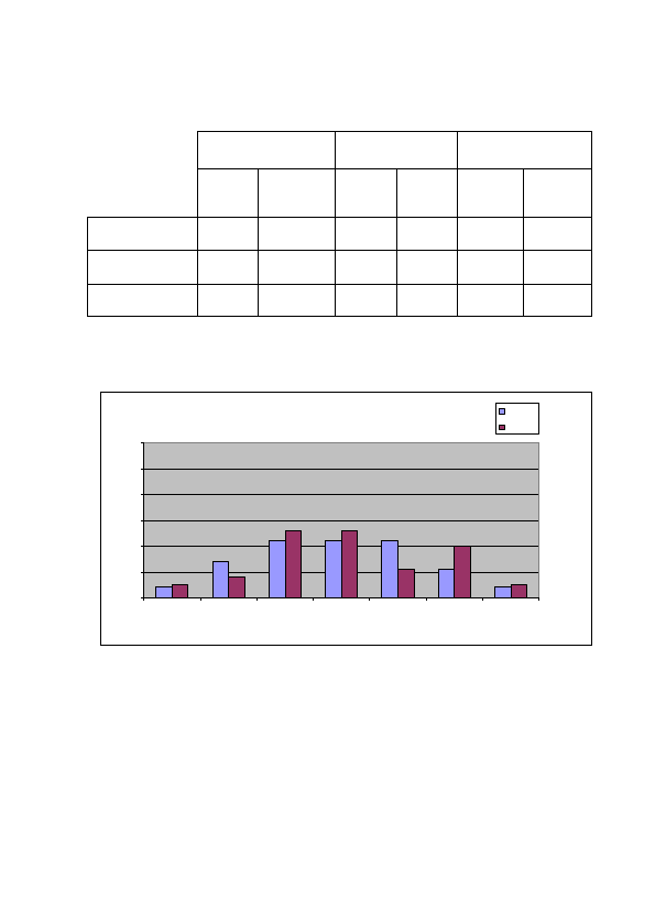
Histograms for Respiratory exchange rate (RER) at peak VO2 at
baseline and 6 month follow-up are provided below:
RER at peak VO2 at baseline
0
10
20
30
40
50
60
≤ 0.79 0.80-0.89 0.90-0.99 1.0-1.09 1.10-1.19 1.20-1.29 ≥ 1.30
RER
Percent of patients
Test
Control
QOL score
VO2 Score
Composite Score
Control
GROUP
Test
GROUP
Control
GROUP
Test
GROUP
Control
GROUP
Test
GROUP
% Improved
75.6
74.7
48.8
67.0
62.2
70.9
% Worsened
24.4
25.3
51.2
31.9
37.8
28.6
% Unchanged
0.0
0.0
0.0
1.1
0.0
0.0
22 – US-ENGLISH
♦ Clinical Results V-V timing
V-V programmable settings were available for the clinical study devices
as follows: ALTO MSP model 617 (not programmable for V-V delay),
ALTO 2 MSP model 627 values (0, 31, 39, 47, 55 and 63 ms) and
OVATIO CRT-D 6750 values (0 to 63 ms in steps of 8 ms).
The graph below shows the programmed V-V settings at
randomization by percentage of patients programmed to each
combination of Synchronous BiV pacing and V-V delay.
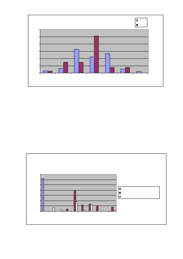
RER at peak VO2 at six months
0
10
20
30
40
50
60
≤ 0.79 0.80-0.89 0.90-0.99 1.0-1.09 1.10-1.19 1.20-1.29 ≥ 1.30
RER
Percent of patients
Test
Control
Programmed V-V Delays
Programmed settings for the 149 of 154 patients optimized
0
5
10
15
20
25
30
35
0 8 16 24 31 37 39 55 60 63
V-V Delay (msec)
% Patients
Synchronous BiV
Synchronous BiV (Left then Right)
Synchronous BiV (Right then Left)

US-ENGLISH – 23
The optimization protocol in the clinical study specified that each
patient randomized should undergo echo guided V-V optimization.
Per the investigational plan for the MSP Clinical Trial, a uniform
protocol was used for V-V programming. This protocol required all
patients to undergo echo-guided V-V delay optimization before
randomization (2 to 14 days post-implant). The optimal V-V delay
was determined by finding the programmable V-V delay and
ventricular chamber pacing order (RV then LV, or LV then RV)
providing the maximum time velocity integral (TVI or VTI) across the
left ventricular outflow tract (LVOT).
Only those patients randomized to the Test arm were required to be
programmed per the optimization protocol for the V-V delay.
Of the 177 patients that presented at randomization, 3 had Model
617 which does not have V-V programmability hence the inability to
optimize. Of the remaining 174 patients, 154 (89%) were tested per
the V-V optimization protocol. One hundred forty-nine (149) of the
154 patients who were tested per the V-V optimization protocol were
programmed per the recommended or randomized V-V delay (97%).
Thirty-one (31) patients were programmed to BiV synchronous (V-V
delay 0ms), 46 were programmed to Sequential BiV (LV then RV), 22
were programmed to Sequential (RV then LV), and the remaining 50
patients were randomized to RV only.
A sub-analysis of the composite endpoint comparing the subset of
CRT-D patients with optimized V-V delays vs. the subset of patients
that did not undergo V-V delay optimization demonstrated similar
results in both groups. The CRT-D patients who did not undergo V-V
delay optimization showed a smaller improvement in the composite
endpoint, although the sample size did not permit conclusions based
on data from this subset.

24 – US-ENGLISH
7. PATIENT SELECTION AND TREATMENT
7.1. INDIVIDUALIZATION OF TREATMENT
Exercise stress testing. If the patient’s condition permits, use
exercise stress testing to:
─ Determine the maximum rate of the patient’s normal rhythm,
─ Identify any supraventricular tachyarrhythmias,
─ Identify exercise-induced tachyarrhythmias.
The maximum exercise rate or the presence of supraventricular
tachyarrhythmias may influence selection of programmable
parameters. Holter monitoring or other extended ECG monitoring
also may be helpful.
CAUTION: When a parameter is reprogrammed during an exercise
stress test, PARAD/PARAD+ algorithm forces acceleration to
"ventricular". During conducted sinus tachycardia within the
programmed Tachy zone, the device detects a 1:1 fast rhythm.
Assuming that acceleration was set to ventricular by reprogramming,
the device concludes for a VT, and immediately applies the
corresponding therapy. This event could have been avoided with
appropriate device handling during tests.
Electrophysiologic (EP) testing: EP testing may be useful for ICD
candidates. EP testing may identify the classifications and rates of all
the ventricular and atrial arrhythmias, whether spontaneous or during
EP testing.
Drug resistant supraventricular tachyarrhythmias (SVTs): Drug
resistant supraventricular tachyarrhythmias (SVTs) may initiate
frequent unwanted device therapy. A careful choice of programming
options is necessary for such patients.

US-ENGLISH – 25
Antiarrhythmic drug therapy: If the patient is being treated with
antiarrhythmic or cardiac drugs, the patient should be on a
maintenance drug dose rather than a loading dose at the time of ICD
implantation. If changes to drug therapy are made, repeated
arrhythmia inductions are recommended to verify ICD detection and
conversion. The ICD also may need to be reprogrammed.
Changes in a patient’s antiarrhythmic drug or any other medication
that affects the patient’s normal cardiac rate or conduction can affect
the rate of tachyarrhythmias and/or efficacy of therapy.
Direct any questions regarding the individualization of patient therapy
to Sorin CRM’s representative.
7.2. SPECIFIC PATIENT POPULATIONS
Pregnancy: If there is a need to image the device, care should be
taken to minimize radiation exposure to the foetus and the mother.
Nursing Mothers: Although appropriate biocompatibility testing has
been conducted for this implant device, there has been no
quantitative assessment of the presence of leachables in breast milk.
Pediatric Patients: This device has not been studied in patients
younger than 18 years of age.
Geriatric Patients: Most of the patients receiving this device in
clinical studies were over the age of 60 years.
Handicapped and Disabled Patients: Special care is needed in
using this device for patients using an electrical wheel chair or other
electrical (external or implanted) devices.

26 – US-ENGLISH
8. PATIENT COUNSELLING INFORMATION
The physician should consider the following points in counselling the
patient about this device:
─ Persons administering CPR may experience tingling on the patient’s
body surface when the patient’s ICD system delivers a shock.
─ Advise patients to carry Sorin CRM ID cards and/or ID bracelets
documenting their ICD system.
9. CONFORMANCE TO STANDARDS
This device was developed in conformance with all or parts of the
following standards:
─ EN 45502-1: 1998 – Active implantable medical devices.
General requirements for safety, marking and information to be
provided by the manufacturer.
─ EN 45502-2-1: 2003 - Active implantable medical devices.
Part 2-1: Particular requirements for active implantable medical
devices intended to treat bradyarrhythmia (cardiac pacemakers).
─ EN 45502-2-2: 2008 – Active implantable medical devices.
Part 2-2: Particular requirements for active implantable medical
devices intended to treat tachyarrhythmia (includes implantable
defibrillators).
─ ISO 5841-3: 2000 Low profile connectors (IS1) for implantable
pacemakers.
─ ISO 11318 (DF-1): Cardiac defibrillator: connector assembly for
implantable defibrillators - Dimensional and test requirements,
August 2002.
─ ANSI/AAMI PC69:2007 Active implantable Medical Devices -
Electromagnetic compatibility - EMC test protocols for implantable
cardiac pacemakers and implantable Cardioverter Defibrillators.
─ IEC 60601-1-2 (2007): Electromagnetic compatibility - Medical
electrical equipment. General requirements for basic safety and
essential performance - Collateral standard

US-ENGLISH – 27
─ EN 50371 (2002) : Generic standard to demonstrate the compliance
of low power electronic and electrical apparatus with the basic
restrictions related to human exposure to electromagnetic fields (10
MHz - 300 GHz)
─ EN 301 489-1 (v1.8.1) & EN 301 489-27 (v1.1.1): Electromagnetic
compatibility and Radio spectrum Matters (ERM); Electromagnetic
Compatibility (EMC) standard for radio equipment and services -
Part 1 : Technical Requirements and Part 27: Specific conditions for
Ultra Low Power Active Medical Implants (ULP-AMI) and related
peripheral devices (ULP-AMI-P)
─ EN 301839-1 (v1.3.1) & EN 301839-2 (v1.2.1): Electromagnetic
compatibility and Radio spectrum Matters (ERM); Short Range
Devices (SRD); Ultra Low Power Active Medical Implants (ULP-AMI)
and Peripherals (ULP-AMI-P) operating in the frequency range 402
MHz to 405 MHz; Part 1: Technical characteristics and test methods
and Part 2: Harmonized EN covering essential requirements of
Article 3.2 of the R&TTE Directive
─ EN 62311 (2008) : Assessment of electronic and electrical
equipment related to human exposure restrictions for
electromagnetic fields (0Hz to 300 GHz)
─ EN 62209-2 (2010) : Human exposure to radio frequency fields from
hand-held and body-mounted wireless communication devices –
Human models, instrumentation and procedures – Part 2: Procedure
to determine the specific absorption rate (SAR) for wireless
communication devices used in close proximity to the human body
(frequency range of 30MHz to 6 GHz)
This information should not be used as a basis of comparisons
among devices since different parts of the standards mentioned may
have been used.
Sorin CRM declares that this device is in conformity with the essential
requirements of Directive 1999/5/EC on Radio and Telecommunications
Terminal Equipment, with the mutual recognition of their conformity
(R&TTE).

28 – US-ENGLISH
Federal Communication Commission Interference Statement 47
CFR Section 15.19 and 15.105(b)
- The FCC product ID is YSGCRTDSONR9770.
This equipment has been tested and found to comply with the limits for a
Class B digital device, pursuant to Part 15 of the FCC Rules. These limits
are designed to provide reasonable protection against harmful
interference in a residential installation. This equipment generates uses
and can radiate radio frequency energy and, if not installed and used in
accordance with the instructions, may cause harmful interference to radio
communications. However, there is no guarantee that interference will not
occur in a particular installation.
This device complies with Part 15 of the FCC Rules. Operation is subject
to the following two conditions: (1) This device may not cause harmful
interference, and (2) this device must accept any interference received,
including interference that may cause undesired operation.
FCC Interference Statement 47 CFR Section 15.21 - No Unauthorized
Modifications
CAUTION: This equipment may not be modified, altered, or changed in
any way without signed written permission from SORIN. Unauthorized
modification may void the equipment authorization from the FCC and will
void the SORIN warranty.
Identification of the equipment according Section 95.1217(a)
This transmitter is authorized by rule under the Medical Device
Radiocommunication Service (in part 95 of the FCC Rules) and must not
cause harmful interference to stations operating in the 400.150-406.000
MHz band in the Meteorological Aids (i.e., transmitters and receivers
used to communicate weather data), the Meteorological Satellite, or the
Earth Exploration Satellite Services and must accept interference that
may be caused by such stations, including interference that may cause
undesired operation. This transmitter shall be used only in accordance
with the FCC Rules governing the Medical Device Radiocommunication

US-ENGLISH – 29
Service. Analog and digital voice communications are prohibited.
Although this transmitter has been approved by the Federal
Communications Commission, there is no guarantee that it will not
receive interference or that any particular transmission from this
transmitter will be free from interference.
IC Requirements for canada
- The IC product ID is 10270A-CRTDSON9770
This class B digital apparatus meets all requirements of the Canadian
Interference- causing equipment regulations.
This device complies with Industry Canada licence-exempt RSS
standard(s). Operation is subject to the following two conditions: (1) this
device may not cause interference, and (2) this device must accept any
interference, including interference that may cause undesired operation of
the device.
Under Industry Canada regulations, this radio transmitter may only
operate using an antenna of a type and maximum (or lesser) gain
approved for the transmitter by Industry Canada. To reduce
potential radio interference to other users, the antenna type and its gain
should be so chosen that the equivalent isotropically radiated power
(e.i.r.p.) is not more than that necessary for successful communication.
This device may not interfere with stations operating in the 400.150–
406.000 MHz band in the Meteorological Aids, Meteorological Satellite,
and Earth Exploration Satellite Services and must accept any interference
received, including interference that may cause undesired operation.

30 – US-ENGLISH
10. PHYSICIAN GUIDELINES
10.1. PHYSICIAN TRAINING
Physicians should be familiar with sterile pulse generator and left
ventricular pacing lead implant procedures. They must apply these
procedures according to professional medical training and experience.
Physicians should be familiar with follow-up evaluation and
management of patients with an implantable defibrillator (or referral
to such a physician).
This training guideline for implantation and follow-up of ICD and
CRT-D devices comes from the Heart Rhythm Society to provide
standards for hospital credentialing bodies to help ensure appropriate
patient care and lead to improved patient outcomes. The following is
a summary of requirements for an alternate training pathway for ICD
and CRT-D implantations(1):
─ Documentation of current experience: 35 pacemaker implantations
per year and 100 implantations over the prior 3 years
─ Proctored ICD implantation experience: 10 Implantations, 5 Revisions
─ Proctored CRT-D implantation experience: 5 implantations
─ Completion of didactic course and/or IBHRE® ExAM
─ Monitoring of patient outcomes and complication rates
─ Established patient follow-up
─ Maintenance of competence: 10 ICD and CRT-D procedures per
year, 20 patients per year in follow-up
(1) Please consult full text of both publications for details. 2004 Heart Rhythm Society
Clinical Competency Statement and the 2005 Addendum on Training Pathways for
Implantation of Cardioverter Defibrillators and Cardiac Resynchronization Devices. Heart
Rhythm (2004) 3, 371-375; Heart Rhythm (2005) 2(10), 1161-1163.

US-ENGLISH – 31
10.2. DIRECTIONS FOR USE
ICD operating characteristics should be verified at the time of
implantation and recorded in the patient file. Complete the Patient
Registration Form and return it to Sorin CRM, as it provides
necessary information for warranty purposes and patient tracking.
Additional programming instructions can be found by accessing
Online Help (click the “?” on the screen) on the Sorin CRM dedicated
programmer. Paper copies of Online Help can be obtained by
contacting your Sorin CRM representative.
10.3. MAINTAINING DEVICE QUALITY
This device is FOR SINGLE USE ONLY. Do not resterilize and
reimplant explanted ICDs.
Do not implant the device when:
─ It has been dropped on a hard surface because this could have
damaged pulse generator components.
─ Its sterility indicator within the inner package is not green,
because it might not have been sterilized.
─ Its storage package has been pierced or altered, because this
could have rendered it non-sterile.
─ It has been stored or transported outside the environmental
temperature limits: 32°F (0°C) to 122°F (50°C) as an electrical
reset condition may occur.
─ "Use Before" date has expired, because this can adversely affect
pulse generator longevity or sterility.

32 – US-ENGLISH
11. PATIENT INFORMATION
Information for the patient is available in the patient booklet,
contained in the outer storage package. Additional copies can be
obtained by contacting your Sorin CRM representative or on the
Sorin CRM's web site: http://www.sorin.com. This information should
be given to each patient with their first ICD and offered to the patient
on each return visit or as deemed appropriate.
12. HOW SUPPLIED
12.1. STERILITY
The PARADYM RF defibrillators are supplied one per package in a
sterile package.
12.2. WARRANTY AND REPLACEMENT POLICY
Sorin CRM warrants its defibrillators. Refer to the section “Warranty” for
additional information. Please see the following labelling sections for
information concerning the performance of this device: Indications,
Contraindications, Warnings and Precautions, and Adverse Events.
13. DEVICE DESCRIPTION
The PARADYM RF CRT-D system includes the model 9770 ICD
device and programming system. The programming system includes
the Sorin CRM Dedicated programmer with the SMARTVIEW
programming software connected to a CPR3 programming head. The
programming system is configured and furnished by Sorin CRM.
The PARADYM RF SonR CRT-D 9770 can serves as a defibrillation
electrode (active housing) with a total surface area of 76 cm².

US-ENGLISH – 33
The PARADYM RF SonR CRT-D 9770 is designed to recognize and
treat slow or fast VT and VF by continuously monitoring atrial and
ventricular activity to identify persistent ventricular arrhythmias and to
deliver appropriate therapies. PARADYM RF SonR CRT-D 9770
features the PARAD/PARAD+ algorithm, which is specifically designed
to differentiate ventricular tachycardias from fast rhythms of
supraventricular origin. PARAD/PARAD+ continuously monitors R-R
interval stability, searches for long cycles, assesses the degree of P-R
association, evaluates sudden onset and determines the chamber of
arrhythmia acceleration.
In addition to the advanced detection scheme, PARADYM RF SonR CRT-
D 9770 offers programmable single, dual or triple-chamber pacing
therapy (DDD, DDI, VVI or SafeR modes) with or without rate-
responsive capabilities (DDDR, DDIR, VVIR, DDD/DDIR and SafeR-
R modes) using an acceleration sensor. An automatic AV delay
algorithm as well as a mode switching function are available.
PARADYM RF SonR CRT-D 9770 enables an adjustment of the
interventricular delay, and provides the possibility of adapting pacing to
each ventricle. The ICD is intended to resynchronize uncoordinated
contraction of the heart by simultaneously or sequentially pacing both
ventricles.
PARADYM RF SonR CRT-D 9770 offers tiered therapy. Therapies can
be programmed independently in each zone:
― in the Slow VT and VT zones: two ATP programs, up to
two shocks with programmable energy and up to four
shocks with maximum energy can be programmed;
― in the VF zone: one ATP program, up to two shocks with
programmable energy and up to four shocks with
maximum energy can be programmed.
The ATP can be applied in RV, LV or RV and LV pacing with a VV
delay equal to 0 ms. ATP pacing configuration is independent of
ventricular pacing configuration.

34 – US-ENGLISH
When the rhythm changes from one zone to another, the device
delivers the therapy programmed in this zone, starting with the same
or more aggressive program for the area. The ATP program in the
VF zone will only be applied if the VT coupling interval is longer than
the programmed fast VT cycle length.
The PARADYM RF SonR CRT-D 9770 offers biphasic shocks with a
maximum stored energy of 42 J.; all automatic shocks are delivered in a
non-committed way. The shock configuration (electrodes used to apply
the shock) can be chosen by programming one of the following
combinations: can and one coil, can and 2 coils, 2 coils only.
Other features are as follows:
─ Automatic ventricular sensitivity control
─ Non-committed shocks
─ Electrophysiological studies (EPS) with real-time markers or
electrograms:
─ Programmer-controlled VT induction sequences,,
─ Programmer-controlled VF inductions (30 Hz rapid pacing or
shock on T),
─ Programmable electrogram vectors (EGM A, EGM V,
RVcoil-CAN, SVC-CAN, RVcoil-SVC, LV bip, LV tip-RV)
─ Real-time annotations displayed with the markers and
indicating the majority rhythm,
─ Manual ATP sequences,
─ Manual shocks.
─ Rescue shock
─ Follow-up tests:
─ Pacing lead impedance,
─ Coil impedance,
─ Capacitor charge time,
─ Sensitivity test
─ Pacing threshold tests.

US-ENGLISH – 35
─ Data storage:
─ Therapy History Report,
─ Statistics (pace/sense, therapy, shocks, and battery voltage),
─ Up to 14 complete Holter records with event logs, marker
channel notation, and electrogram records.
The connector head has five ports:
─ Atrial “sonR” port: performs atrial bipolar pace/sense if a
conventional IS-1 lead is connected.
─ RV “IS-1” port: performs right ventricular bipolar pace/sense.
─ LV “IS-1” port: performs left ventricular bipolar pace.
─ RV “DF-1” ports for RV defibrillation coil.
─ SVC “DF-1” port for SVC defibrillation coil.
Distal lead terminal connections are secured with set-screws accessed
via self-sealing silicone plugs. All lead connections pass through the
header into the device via feedthroughs.
Programming System: The Sorin CRM programmer is used in
conjunction with specific programmer software to interrogate and
program the implanted device at implant and during patient follow-up
procedures.
14. IMPLANT PROCEDURE
14.1. NECESSARY EQUIPMENT
Implantation of PARADYM RF SonR CRT-D 9770 requires the
following equipment:
─ Sorin CRM Dedicated programmer, equipped with the
SMARTVIEW software interface and with the programming head,
─ pacing system analyzer, as well as its sterile connecting cables,
to evaluate the pacing and sensing thresholds,
─ a complete set of leads with corresponding introducers,

36 – US-ENGLISH
─ physiological signal monitor capable of displaying simultaneously
the surface ECG and arterial pressure,
─ an external defibrillator with sterile external paddles,
─ sterile cover for the telemetry head.
14.2. PACKAGING
♦ Contents
The PARADYM RF SonR CRT-D 9770 and its accessories are
ethylene oxide sterilized and hermetically sealed in two-ply clear
packaging meeting international requirements.
The sterile packaging contains a defibrillator, one screwdriver, and
an insulating plug for the DF-1 defibrillation connector.
The non-sterile items contained in the outer storage package are the
implant manual, the ICD Registration Form and its envelope, the
patient booklet, the ICD ID card and 12 identification labels.
Once delivered, PARADYM RF SonR CRT-D 9770 is programmed to
as-shipped values that are different from nominal values (see
Chapter “Programmable Parameters” for details).
14.3. OPTIONAL EQUIPMENT
The following equipment may be required during implantation
of PARADYM RF SonR CRT-D 9770:
─ an IS-1 insulating plug to close the atrial port
─ sterile water to clean traces of blood. Any parts cleaned with
sterile water must be thoroughly dried.
─ mineral oil to lubricate if necessary
─ a lead cap to isolate a lead which is not used

US-ENGLISH – 37
14.4. BEFORE OPENING THE PACKAGE
Before opening the package, check the "Use Before" date printed on the
labels on the box and on the sterile package. Defibrillators that have not
been implanted before that date should be returned to Sorin CRM.
Devices MUST NOT be interrogated and programmed within the vicinity
of other devices.
Also check the integrity of the sterile package. The sterility of the
contents is no longer guaranteed if the package has been pierced or
altered. If the defibrillator is no longer sterile, it should be returned in
its packaging to Sorin CRM. Any re-sterilization of the unit is at the
discretion of Sorin CRM.
14.5. PRIOR TO IMPLANTATION
Use the programmer to verify the defibrillator can be interrogated
before implantation.
Verify all shock therapies are disabled in order to avoid accidental
discharge during implantation.
It is not advisable to program the Smoothing function before
implantation, since the defibrillator may detect noise and pace at a
rate higher than the programmed basic rate.

38 – US-ENGLISH
CAUTION: Do not shake or tap sharply on the ICD package with the
ICD inside, because the ICD's sensing circuits can interpret this as P-
waves or R-waves and record these as an arrhythmia episode.
If unusual shaking or tapping of the package results in a stored
arrhythmia episode, erase the recording before using the ICD.
14.6. DEVICE PLACEMENT
The pocket should be prepared in the left pectoral position, either
subcutaneously or submuscularly. Subcutaneous device implantation
is recommended for optimal RF communication efficacy.
Implantation in an abdominal position is not advisable.
In its final position, the defibrillator should be no more than 4 cm
below the skin surface.
14.7. CHOOSING THE TYPE OF LEAD
The defibrillator should be connected to:
─ one bipolar atrial sensing/pacing lead with or without dedicated
SonR sensor
─ one right ventricular lead with bipolar sensing/pacing electrodes,
and one or two defibrillation coils,
─ one unipolar or bipolar left ventricular pacing lead.
The choice of leads and their configuration is left to the implanting
physician’s judgment according to the clinical investigation.
Note: In case no atrial lead is implanted, the atrial port should be
plugged with IS-1 insulating plug and a single chamber mode (VVI-
VVIR) should be programmed. PARAD and PARAD+ should not be
used.
US-ENGLISH – 39
Connectors: The ventricular connectors are compatible with the IS-1
standard and the defibrillation connectors are compatible with the
DF-1 standard (refer to the “Lead evaluation and lead connection”
sub-section in the “Warnings and precautions” section). Shock
configuration (+ -> -)
The shock configuration is the energy pathway between the
defibrillation electrodes. If an atrial coil is present, the shock
configuration can be programmed for bi-directional shocks.
Programming: When active case and SVC are both programmed to
Yes, the shock configuration can be programmed to:
─ RV to Case (or Case to RV),
─ or RV to SVC (or SVC to RV),
─ or RV to Case+SVC (or Case+SVC to RV).
The polarity of shock is determined by the parameter itself.
14.8. MEASUREMENT OF THRESHOLDS AT
IMPLANT
Pacing and sensing thresholds should be measured at implant.
RV to Case+SVC
RV to Case
RV to SVC

40 – US-ENGLISH
Pacing thresholds: Acute thresholds should be lower than 1 V (or 2 mA)
for a 0.35 ms pulse width, in both ventricles and in the atrium.
Sensing thresholds: For proper right ventricular sensing, the amplitude
of the R-wave should be greater than 5 mV. For proper atrial sensing, the
amplitude of the P-wave should be greater than 2 mV.
Pacing impedance measurements: Right ventricular, left ventricular
and atrial pacing impedances should range from 200 to 3000 ohms (refer
to the lead characteristics, especially if high impedance leads are used).
14.9. LEAD CONNECTION
Implant the ventricular leads, then the atrial lead.
Each lead must be connected to the corresponding connector port.
The position of each connector is indicated on the casing.
CAUTION: Tighten only the distal inserts.
To connect each lead, proceed as follows:
1. Clean the lead terminal pins thoroughly, if necessary (device
replacement).
2. Lubricate the lead terminal pins with sterile water, if necessary.
3. Do not insert a lead connector pin into the connector block without
first visually verifying that the lead port is not filled with any
obstacle.
4. Insert the screwdriver into the pre-inserted screw socket of the
appropriate port (in order to allow excess air to bleed out and to
make the insertion of the lead pin easier).
5. Insert the lead pin all the way into the port (check that the pin
protrudes beyond the distal insert).
6. Tighten, check the tightness and ensure the lead pin still
protrudes beyond the distal insert, and did not move.

US-ENGLISH – 41
CAUTION: 1. One single set screw is located on the side of the
connection header. 2. Do not tighten the pre-inserted screws when
there is no lead (this could damage the connector). 3. Do not loosen
the screws before inserting the connector (subsequent risk of being
unable to reinsert the screw). 4. Removing the screwdriver: to avoid
all risk of loosening screws during removal, hold the screwdriver by
its metal part and not by the handle. 5. When mineral oil or sterile
water is used to make lead insertion easier, the screwdriver should
remain inserted into the pre-inserted screw socket when checking the
tightness. As a matter of fact, when the lead port is filled with a liquid,
the physics piston effect can give the feeling the lead is properly
tightened.
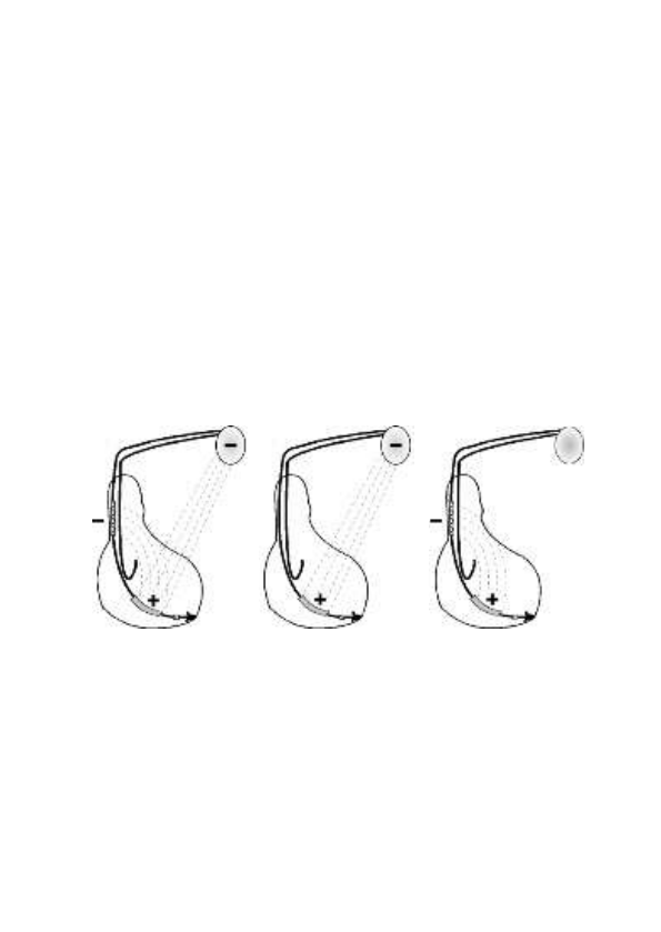
NOTE: To optimise cardioversion/defibrillation shocks, electrodes
must be positioned so that the electric field between anode (s) and
cathode covers the largest myocardial mass. In normal conditions,
the anode and cathode are adequately separated. In case of a short-
circuit, the shock may be aborted to prevent damaging the
defibrillator.
In the case of an external defibrillation shock delivered to the patient,
always check the programming and functioning of the device, in
particular its capacity to deliver shocks.
14.10. DEVICE IMPLANTATION
PARADYM RF SonR CRT-D 9770 should be implanted with the
engraved side facing outwards for optimal communication with the
programming head and radiographic identification.
Carefully wind excess lead and place in a separate pocket to the side
of the defibrillator. It is recommended to not place any excess wire
between the can and the heart.
Suture the casing connector to the muscle using the hole provided
for this purpose, in order to avoid potential migration of the device
into the pectoral muscle.

42 – US-ENGLISH
14.11. TESTS AND PROGRAMMING
During the implant testing procedure, it is recommended that a
security margin of at least 10 J be demonstrated between the
effective shock energy and maximum programmable energy.
Enable shock therapies, then program the defibrillator.
Verify that the defibrillation lead impedance for each shock delivered
ranges from 30 to 150 ohms. Check the lead connection if the values are
outside these boundaries.
Save the programming data on the programmer’s hard disk and on an
external storage device (if desired).
15. SPECIAL MODES
15.1. SAFETY MODE (NOMINAL VALUES)
Nominal values may be rapidly restored by pressing the following
button on the programming head or programmer keyboard:
or via the “Emergency” button on the SMARTVIEW screen.
In safety mode, the defibrillator operates with the parameters
underlined in the table of programmable parameters.
15.2. MAGNET MODE
When the magnet is applied:
─ antiarrhythmia functions are inhibited (detection of rhythm
disturbances, charging, and therapy),
─ hysteresis, VV delay and AVD paced/sensed offset are set to 0,
─ pacing amplitude is set to 6 V,
─ pulse width is set to maximum,

US-ENGLISH – 43
─ pacing rate is set to the magnet rate,
─ the following functions are disabled: ventricular arrhythmia
prevention, Mode Switch, Anti-PMT, Smoothing, Rate Response.
When the magnet is removed:
─ the sensor rate is forced to the basic rate,
─ arrhythmia detection algorithms and sequential therapies are
reinitialized,
─ therapies start with the least aggressive program for each area.
The other parameters remain at their programmed value, including
the ventricular paced chamber parameter.
NOTE: The magnet is inactive during telemetry.
The magnet rate values are as follow:
Magnet rate (bpm)
96
94
91
89
87
85
Magnet period (ms)
625
641
656
672
688
703
Magnet rate (bpm)
83
82
80
78
77
Magnet period (ms)
719
734
750
766
781
15.3. RESPONSE IN THE PRESENCE OF
INTERFERENCE
If the defibrillator senses electrical noise at a frequency above 16 Hz,
it switches to an asynchronous mode at the basic rate.
The programmed mode is restored as soon as the noise is no longer
detected.
Ventricular pacing is also inhibited by ventricular noise. It can be
restored by setting the parameter V pacing on noise to Yes.
44 – US-ENGLISH
15.4. DETECTION CHARACTERISTICS IN THE
PRESENCE OF ELECTROMAGNETIC FIELDS
Per Clause 27.4 of Standard EN 45502-2-2, detection in the
presence of electromagnetic fields is characterized as follows:
Differential mode:
Common mode rejection ratio:
16.6 Hz
50 Hz
60 Hz
Atrial channel
≥ 75 dB
67 dB
67 dB
Ventricular channel
≥ 69 dB
≥ 69 dB
≥ 69 dB
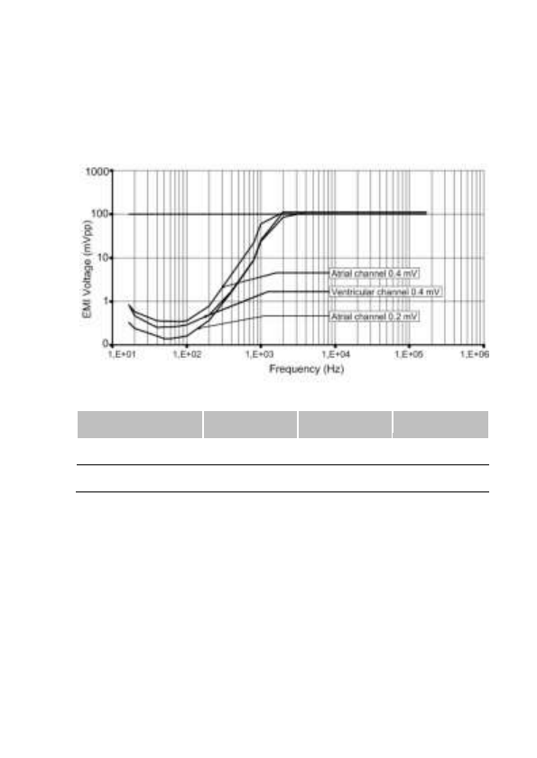
Modulated interference: For atrial sensitivity setting of 0.2 mV,
compliance to the Cenelec standard 45502-2-2 is met for a maximum
test signal amplitude of 8 V for the frequency of 60 MHz. 0.4 mV
complies with the standard for the whole frequency range.
15.5. PROTECTION AGAINST SHORT-CIRCUITS
The defibrillator can undergo a short-circuit if the anode and cathode
are not adequately separated.
In this case, the shock is aborted to prevent damaging the

US-ENGLISH – 45
defibrillator and a warning will indicate that a short circuit (shock
impedance < 20 ohms) was detected during the last shock.
16. MAIN FUNCTIONS
16.1. AUTOMATIC LEAD MEASUREMENTS
Automatic pacing lead impedance measurement: A lead impedance
measurement is automatically performed on atrial and ventricular leads
every 6 hours. The daily mean impedance is stored for each chamber.
Automatic coil impedance measurement: A coil impedance
measurement is automatically performed on RV and SVC coils once a
week. The result is stored in the device memory.
16.2. ATRIAL TACHYARRHYTHMIA MANAGEMENT
Mode Switch: This function is designed to limit the acceleration and
variation of ventricular rate in the presence of atrial arrhythmia.
16.3. VENTRICULAR TACHYARRHYTHMIA
MANAGEMENT
Ventricular tachyarrhythmia prevention: Set of algorithms that can be
used to avoid the circumstances of ventricular tachyarrhythmia onset.
Searching for a long cycle (P And R based Arrhythmia Detection+:
PARAD+): Additional arrhythmia classification criterion to improve
identification of atrial fibrillation and avoid inappropriate shocks.
Fast VT treatment: Applies detection criteria on fast ventricular
tachycardia, that are different from those of the VT zone, as well as
different therapies. The fast VT zone is included in the VF zone: its
lower limit is determined by the programmed value for the VF zone
and its upper limit by the programmed value for the fast VT zone.

46 – US-ENGLISH
Polarity alternation on Max shock: Reverses the programmed polarity
of every second shock set at maximum energy. The number, type, and
energy of shocks is independently programmable by detection zone.
16.4. PACING
BTO (Brady Tachy Overlap): Enables cardiac resynchronization
therapy within the slow VT zone to preserve patient exercise
capacity, without affecting detection or treatments of slow VTs.
Post-shock mode: After any automatic shock therapy, the post-shock
mode makes it possible to apply a pacing mode other than the standard
antibradycardia pacing mode and/or with different pacing parameters.
SafeR (AAI <> DDD) mode: Is intended to minimize deleterious
ventricular pacing. The defibrillator functions in AAI mode, and
temporarily switches to DDD mode upon the occurrence of AVB III,
AVB II, AVB I and ventricular pause.
Anti-PMT protection: Is intended to protect the patient from
Pacemaker-Mediated Tachycardia (PMT) without reducing atrial
sensing capability of the device.
16.5. SENSING
Automatic Refractory Periods: Optimize sensing and make the
implant progamming easier. These periods are composed of a
minimal Refractory Period and a triggerable Refractory Period. The
duration of the refractory periods lengthens automatically as needed.
Committed period: In DDI or DDD modes, the committed period is a
non-programmable 95 ms ventricular relative refractory period that
starts with atrial pacing. If a ventricular event is sensed during the
committed period, but outside the blanking period, the ventricle is
paced at the end of the committed period. The committed period
prevents inappropriate ventricular inhibition if crosstalk occurs.
Protection against noise: Allows the distinction between ventricular

US-ENGLISH – 47
noise and ventricular fibrillation. If the device senses ventricular noise, the
ventricular sensitivity is decreased until noise is no longer detected.
Ventricular pacing can be inhibited to avoid a potential paced T-wave.
Automatic sensitivity control: Optimizes arrhythmia detection and
avoids late detection of T-waves and over-detection of wide QRS
waves. The device automatically adjusts the sensitivities based on
the ventricular sensing amplitude. In case of arrhythmia suspicion or
after a paced event, the programmed ventricular sensitivity will be
applied. The minimum ventricular sensitivity threshold is 0.4 mV
(minimum programmable value).

48 – US-ENGLISH
16.6. SONR CRT OPTIMISATION
SonR is a specific sensor, located at the tip of the atrial lead, that
picks-up micro-accelerations of the heart walls to derive information
pertaining to cardiac contractility. The signal picked-up by the SonR
sensor can be processed by PARADYM RF SonR CRT-D 9770 in
order to automatically adjust VV delays and AV delays during rest
and exercise for optimal resynchronization therapy. In addition, the
SonR signal is recorded during tachyarrhythmia episodes to depict
acute variations of cardiac contractility. PARADYM RF SonR CRT-D
9770 can also transmit real-time SonR signals via telemetry.

US-ENGLISH – 49
16.7. FOLLOW-UP FUNCTION
Storage of memory data: AIDA+ (Automatic Interpretation for
Diagnosis Assistance) software provides access up to 6 months of
patient follow-up with day by day data collection, or up to 24 hours
with hourly data collection. Episodes of ventricular tachyarrhythmia
are recorded with the programmable EGM channels: either by
selecting up to two traces, or by selecting "Double V" which enables
a one-channel recording that is twice as long.
Alerts / Warnings: The device routinely performs security self-
checks and technical measurements to ensure system integrity.
When system integrity is found to be at risk outside a follow-up, alerts
are stored in the device memory. When system integrity is found to
be at risk during a follow-up, the information is managed as a
warning (pop-up message) to notify immediately the user. For
example, the following types of event can trigger a warning or an
alert: technical problem during a shock, pacing lead impedance or
coil impedance measurements out-of-range, battery depletion,…

50 – US-ENGLISH
16.8. REMOTE MONITORING FUNCTION
Remote monitoring enables the automatic remote transmission of
implant data to the physician thanks to the wireless Radio Frequency
(RF) communication ability of the implant in order to provide a
comprehensive report to the physician about device functioning and
patient cardiac status without having the patient physically in the clinic.
The data is transmitted from the implant and the SMARTVIEW
monitor, a small transmitter placed in the patient home.
Implant data are first transmitted to the SMARTVIEW monitor via RF.
Data are then rooted through the phone network to an internet
website. This website is responsible for transforming the implant data
into a comprehensive report that can be consulted by the physician.
SMARTVIEW Monitor
The SMARTVIEW monitor is a small device equipped with an RF
transmission module to communicate with the implant and a modem
to export data through the internet.
The SMARTVIEW monitor is delivered to the patient who has to
install it at home. Preferably the SMARTVIEW monitor will be placed
on the nightstand of the patient, as close as possible to the side of
the bed the patient usually sleeps. The SMARTVIEW monitor shall
be connected to the phone network and the power plug. Regular
transmissions are done during the night when the patient is asleep
next to the SMARTVIEW monitor without any intervention from the
patient.
Transmission trigger
There are 3 different triggers for a remote transmission:
─ the remote follow-up transmission is scheduled by the physician to
occur regularly (according to the programming).
─ the alert transmission will take place when the implant has recorded
an abnormal event. The list of abnormal event is available in a
following paragraph. Alert conditions are checked daily.

US-ENGLISH – 51
─ the on-demand follow-up transmission is triggered by the patient
himself through the use of a specific button on the remote-monitor.

52 – US-ENGLISH
Data transmitted
The data transmitted are identical to the data available during a
standard interrogation with the Orchestra Plus programmer. All
counters, histograms, IEGMs and diagnosis available in the device
are transmitted containing (not exhaustive list):
─ programmed parameters
─ Information on patient and system implanted
─ battery status
─ lead status (brady leads and defibrillation coils)
─ pacing counters and mean heart rate (brady)
─ atrial and ventricular arrhythmia counters and episodes
─ ventricular therapy counters
─ heart failure monitoring
Data are presented in the form of 2 reports to the physician: the first
one contains a summary of major counters, histograms, warnings
and diagnosis. The second one presents the 3 most important IEGM
episodes automatically selected based on the degree of severity for
the patient.
User website
On the website, the physician is able to:
─ consult and schedule the remote follow-ups of their patient
─ configure additional ways of being notified of alerts (for instance by
SMS, fax or e-mail
─ consult, print and export patient reports

US-ENGLISH – 53
Alert system
The following set of alert trigger can be independently programmed
ON/OFF by the physician using the Orchestra Plus programmer and
can trigger an alert transmission:
─ Reset of the device
─ ERI reached
─ Low or high impedance (A, RV, LV)
─ Abnormal coil impedance (shock lead)
─ Low or High shock impedance
─ Long charge time
─ Inefficient high energy shock
─ All shocks programmed OFF
─ Shock treated VT/VF
─ Lack of V pacing in CRT device
─ Suspicion of noise on the V lead
─ AT/AF occurrence
─ Fast V rate during AT/AF
WARNINGS
The use of remote monitoring does not replace regular follow-up.
Therefore, when using remote monitoring, the time period between
follow-ups visits may not be extended.
When ERI mode is reached, this information is transmitted via the
remote monitoring facility and then the remote-monitoring is switched
off to preserve battery life.

54 – US-ENGLISH
17. PATIENT FOLLOW-UP
17.1. FOLLOW-UP RECOMMENDATIONS
Before the patient is discharged and at each subsequent follow-up
visit, it is advisable to:
─ check the occurrence of system warnings,
─ check the battery status,
─ check the integrity of the pacing and defibrillation leads,
─ check for proper sensing (sensitivity, crosstalk) and pacing ; set
the pacing amplitude to twice the pacing threshold,
─ interrogate the implant memories (AIDA+),
─ check the efficacy of the therapies delivered,
─ keep a printout of programmed parameters, test results, and
memory data,
─ reset the memory data and statistics.
These operations should be performed by medical personnel in an
appropriate care unit, with resuscitation equipment present.
It is recommended that a routine follow-up examination be done one
month after discharge, and then every three months until the device
nears the replacement date.
After a device reset, the magnet rate is equal to 87 ppm; it will be
updated within the next 24 hours.
Refer to the online help for a description of displayed warning, and
the necessity to contact Sorin CRM for an evaluation.
Implant software upgrade: in case a new implant software is
downloaded in the device memory through the programmer, a
warning message could be displayed by the programmer to inform
the user and give the proper instructions to follow.

US-ENGLISH – 55
17.2. HOLTER FUNCTION
The Holter records up to 14 tachyarrhythmia episodes as well as the
therapy history.
STORED EPISODES
PARADYM RF SonR CRT-D 9770 stores up to 14 episodes (VF, VT,
Slow VT, SVT/ST, non-sustained).
For each episode four levels of details are presented:
─ Tachogram (to visualize PP and PR intervals)
─ Event log for the entire episode:
─ PARAD/PARAD+ analysis for each majority,
─ Delivered therapies,
─ Markers: Atrial, ventricular and biventricular markers, sensed,
paced and in relative refractory periods,
─ EGM: onset and detection of the arrhythmia, on two therapies,
and the return to slow rhythm by recording electrogram.
Therapy history: For each arrhythmia detection, each therapy
delivered (either automatically or during an electrophysiological
study) and at the end of each arrhythmia, PARADYM RF SonR CRT-
D 9770 records the type of majority rhythm, the number of ATP
sequences delivered, the energy and the number of shocks
delivered.

56 – US-ENGLISH
17.3. ELECTIVE REPLACEMENT INDICATOR (ERI)
Elective Replacement Indicators (ERI)(1) are:
─ magnet rate equal to 80 ± 1 min-1 or
─ battery voltage equal to 2.66 V ± 0.01 V
CAUTION: The defibrillator should be replaced as soon as the
Elective Replacement Indicator (ERI) point is reached.
Between the ERI and the EOL (End of Life)(2), PARADYM RF SonR
CRT-D 9770 can still function for:
─ 7.4 months (100% atrial and biventricular pacing in DDD mode,
500 ohms, with as-shipped settings), and deliver 7 shocks at
34 J or
─ 6.4 months (0% pacing, sensors OFF, one 42 J shock every
2 weeks).
Once the Elective Replacement Indicator (ERI) point has been
reached, the device operates normally, except that the charge time
increases. Under normal conditions (and without programmer use)
the charge times are as follows:
Shock energy
Charge time (sec)
BOL
42 J
10 (± 2)
ERI
42 J
13 (± 3)
(1) Elective Replacement Indicators (ERI) corresponds to
Recommended Replacement Time (RRT) as referred in the EN45502-
2-2 standard.
(2) End of Life (EOL) corresponds to End of Service (EOS) as
referred in the EN45502-2-2 standard.

US-ENGLISH – 57
17.4. EXPLANTATION
The defibrillator should be explanted in the following cases:
─ The Elective Replacement Indicator (ERI) point is reached
─ Confirmed malfunction
─ Burial of the patient (for environmental reasons, the local
regulation may require the explantation of the devices containing
a battery supply)
─ Cremation of the patient (the defibrillator may explode if placed in
an incinerator).
The explanted defibrillator should not be reused in another patient.
All explanted defibrillators should be returned to Sorin CRM, carefully
cleaned of all traces of contamination. This may be done by
immersing them in an aqueous sodium hypochlorite containing at
least 1% chlorine, followed by rinsing copiously with water.
The defibrillator should be protected against mechanical impact and
the temperature variations that may occur during shipping.
Before explantation, it is advisable to:
─ print out all programmed parameters, statistics and Holter
function report,
─ save Patient data on floppy disk or hard disk,
─ disable shock therapies (VT and VF) to avoid any risk of untimely
shock.

58 – US-ENGLISH
17.5. DEFIBRILLATOR IDENTIFICATION
The defibrillator can be interrogated and programmed via telemetry,
using the programming head interfaced with the Sorin CRM
dedicated programmer.
Position the programming head over the telemetry antenna located in
the upper part of the device, in order to communicate effectively via
telemetry (see diagram below).
The device can be non-invasively identified as follows:
1. Take an X-ray to identify the name of the manufacturer and
model, printed on the device (x-ray ID is SDE : S = SORIN; D =
Defibrillator; E = PARADYM RF SonR CRT-D 9770):
2. Interrogate the device using the Sorin CRM dedicated
programmer. The model and serial number of the device are
automatically displayed. The first figure in the serial number
corresponds to the last figure in the year of manufacture.

US-ENGLISH – 59
18. SUPPLEMENTAL INFORMATION
Clinical data presented in this section are from the SafeR clinical
study. SafeR operation in PARADYM RF is similar to that in the
Symphony pacemaker. The data provided are applicable to
PARADYM RF SonR CRT-D 9770.

60 – US-ENGLISH
18.1. ADVERSE EVENTS IN THE SAFER STUDY
Clinical study of the SafeR included 45 Symphony 2550 devices
implanted in 45 patients. No serious adverse events were device- or
feature-related. There were no deaths in the study.
Table 1 summarizes the safety data for this study.

US-ENGLISH – 61
Table 1: Summary of Symphony safety data during study
Patients
Number of events
Number of
patients
% of
patients
Number of
events
Events per
device
year (a)
Deaths
0
0
0
0
Explants
0
0
0
0
Serious pacemaker
related events outside
the use of SafeR
0
0
0
0
Non-serious
pacemaker related
events outside the
use of SafeR
0
0
0
0
Serious events due to
the use of SafeR
0
0
0
0
Non-serious events
related due to the use
SafeR
13
28.9
15
3.2
Serious non-
pacemaker related
events
6
13.3
9
1.9
Non-serious non-
pacemaker related
events
8
17.8
8
1.7
(a) 4.74 device years

62 – US-ENGLISH
Non-serious events due to the use of SafeR included: delay in
switching on 2nd degree AV block, inappropriate classification of a
PAC, disagreement between markers and recorded EGM, atrial
pacing above the maximum rate, recycling on an r-wave in a
refractory period, and disagreement in the statistics for switches to
DDD. No patient symptoms were associated with these events.

US-ENGLISH – 63
18.2. SAFER CLINICAL STUDY
SafeR mode in PARADYM RF is similar to that in Symphony.
The differences in SafeR mode between the two devices are:
─ To prevent long RR intervals during VT/VF, SafeR has no effect
during VT/VF therapy, electrophysiologic studies, and post-shock
recovery.
─ The maximum acceptable AV delay for first degree AV block
varies as a function of pacing rate.
─ PARADYM RF requires a ventricular sensed event to atrial paced
event (RA) interval of at least 100 ms. Therefore, the device
lengthens the atrial escape interval so that it ends at least 102
ms after the ventricular event.
─ During atrial fibrillation episode, pause criterion is fixed to 2s to
avoid long bradycardia episodes in switching to DDD mode.
Despite these differences, the data collected on Symphony devices
are applicable to PARADYM RF because the principles of SafeR
operation did not change. The criteria for switching from AAI to DDD
(or vice versa) did not change. The device’s method for evaluating
the presence of AV conduction did not change.
Methods: All patients were implanted with a Symphony Model 2550 dual-
chamber rate-responsive pacemaker with SafeR mode. A variety of
marketed atrial and ventricular pacing leads were used. The pacemaker
was programmed and interrogated via bi-directional telemetry using a
Sorin CRM dedicated programmer and a CPR3 programming head.
The study’s routine evaluation consisted of enrollment, pre-discharge
evaluation, and a scheduled follow-up visit at one month. At pre-
discharge, a 24-hour Holter recording was performed and pacemaker
memory was read. At one month, pacemaker memory was read.
Investigators also documented adverse events.
Patients studied: A total of 45 patients from 12 centers had Symphony
2550 pacemakers with SafeR. Of these, 14 (31 %) were female and 31
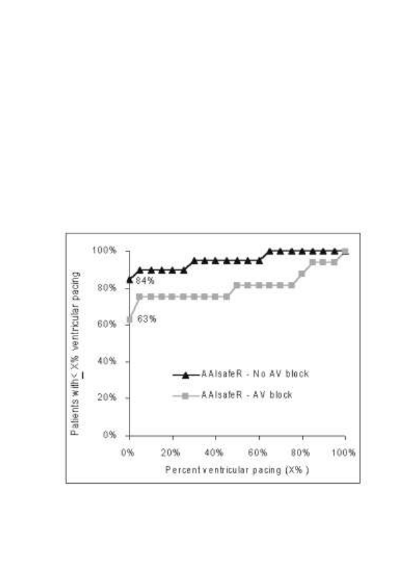
64 – US-ENGLISH
(69 %) were male. Mean patient age (± SD) was 74 ± 9 years.
Primary indications for implant were: 1st degree AV block (11.1 %),
2nd degree AV block (6.7 %), 3rd degree AV block (22.2 %), sinus
node dysfunction (62.2 %) or other (6.7 %).
Effectiveness results: To determine the effectiveness of SafeR
mode, the percentage of ventricular pacing provided over one month
was recorded from pacemaker memory.
Thirty-five patients contributed data to evaluate the percentage of
ventricular pacing provided with SafeR. Twenty-nine patients had 1
% or less ventricular pacing and six patients had a range of 28-97 %
ventricular pacing. The graph below shows the distribution of
ventricular pacing observed in patients with and without AV block as
a primary indication for implant.
The graph shows that many patients programmed to SafeR had less
than 1% ventricular pacing:

US-ENGLISH – 65
84 % of patients without AV block at implant.
63 % of patients with AV block at implant.
In a representative reference group(1) of patients programmed to DDD,
none had less than 1 % ventricular pacing and only 10 % had less than
90 % ventricular pacing regardless of AV block indication at implant.
The actual reduction of ventricular pacing that SafeR provides in an
individual will depend on the amount of time that the patient spends
in AV block. SafeR cannot and should not provide any decrease in
ventricular pacing while the patient is in AV block.
(1) Pioger G, Jauvert G, Nitzsché R, Pozzan J, Laure H, Zigelman M, Leny G, Vandrell M,
Ritter P, and Cazeau S. Incidence and predictive factors of atrial fibrillation in paced
patients. PACE, 28, Supp 1: S137-141; January 2005. This was a prospective
observational study of 377 patients with a functionally similar device programmed to
DDD. The primary indications for implant were: AV block (49 %), sinus node disease (16
%), brady-tachy syndrome (5 %), AV block + sinus node disease (19 %), AV block +
brady-tachy syndrome (6 %), and brady-tachy syndrome + sinus node disease (5 %).

66 – US-ENGLISH
19. PHYSICAL CHARACTERISTICS
Dimensions
69.5 x 73.4 x 11 mm
Weight
95 g
Volume
38.6 cm3
Active surface area of casing
76 cm2
Connector
Atrium: SonR. Right ventricle: IS-1,
DF-1. Left ventricle: IS-1.
19.1. MATERIALS USED
Active surface area of casing
99% pure titanium
Connectors
Polyurethane* and silicone elastomer*
DF-1 insulating plug
silicone elastomer*
*Medical-grade materials that have undergone “in vitro” and “in vivo”
qualifications.
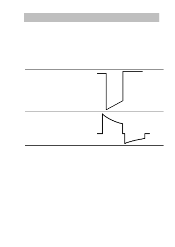
US-ENGLISH – 67
20. ELECTRICAL CHARACTERISTICS
Atrial input impedance
80 kilohms ± 30 %
Ventricular input impedance
80 kilohms ± 30 %
D.C. capacitance
148 µF ± 8 %
Capacitor formation
No formation required
Rate limit
192 min-1 ± 10 min-1
Pacing waveform
Defibrillation waveform

68 – US-ENGLISH
20.1. TABLE OF DELIVERED SHOCK ENERGY
AND VOLTAGE
The relationship between stored energies, maximum voltages and
delivered energies (at 37 °C, 50 ohm load) for the minimum, low,
mean and maximum programmed energy values is as follows:
Stored energy (J)
0.5
10
20
34
42
V1 (Volt)
75
341
483
631
702
V2 (Volt)
37
173
245
318
353
Delivered E: Phase 1 (J)
0.31
7.0
14.0
23.9
29.6
Delivered E: Phase 2 (J)
0.08
1.8
3.6
6.1
7.5
Delivered E: Total (J)
0.4
8.8
17.6
30.0
37.1
Tolerances are 12% for voltage (25% at 0.5 J) and 30% for energy.

US-ENGLISH – 69
20.2. BATTERY
Manufacturer
Greatbatch
Type
Quasar High Rate (QHR)
Model
GB 2593
Number of batteries
1
Total capacity
1964 mAh
Usable capacity
Between BOL and ERI: 1278 mAh.
Between BOL and EOL: 1675 mAh.
Voltage
BOL: 3.25 V. ERI: 2.66 V. EOL: 2.5 V.
20.3. LONGEVITY
The longevities mentioned below are calculated by taking into
account 6 months storage.
5.1 years
Biventricular pacing in DDD mode, 100%, 500 ohm, 3.5 V, 0.35 ms,
60 min-1, one 42 J shock per quarter, sensors OFF
4.6 years
Biventricular pacing in DDD mode, 100%, 500 ohm, 3.5 V, 0.35 ms,
60 min-1, one 42 J shock per quarter, sensors (G, SonR) ON
6.0 years
Biventricular pacing in DDD mode, 1% in atrium, 100% in both
ventricles, 500 ohm, 3.5 V, 0.35 ms, 60 min-1, one 42 J shock per
quarter, sensors OFF
4.2 years
Biventricular pacing in DDD mode, 15% in atrium, 100% in both
ventricles, 500 ohm, 4.5 V, 0.50 ms, 60 min-1, one 42 J shock per
quarter, sensors OFF
9.0 years
0% pacing, one 42 J shock per quarter, sensors OFF
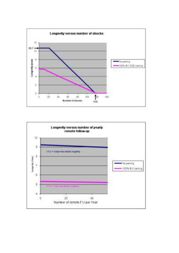
70 – US-ENGLISH
The mean longevity as a function of shocks delivered at maximum
energy, with and without pacing, is as follows:
The mean longevity as a function of yearly remote follow-ups(1), with
and without pacing, is as follows:
(1) An excessive number of remote follow-up can have a non-
negligible impact on device longevity.

US-ENGLISH – 71
21. PROGRAMMABLE PARAMETERS
measured at 37 °C under a 500 ohm load
Legend:
Value in bold: “as shipped” value
Underlined value: nominal value
21.1. ANTIBRADYCARDIA PACING
Basic parameters
Values
Mode
VVI-VVIR-DDD-DDDR-DDD/DDIR-DDI-DDIR-
SafeR (AAI <=> DDD)-SafeR-R (AAIR <=> DDDR)
Basic rate (min-1) (1)
From 30 to 90 by steps of 5; 60 (± 4 %)
Maximum rate (min-1)
From 100 to 145 by steps of 5; 120 (± 6 %)
Rate hysteresis (%)
0-5-10-20-35 (± 18 ms)
Rest AV delay (ms)
30-40-45-55-65-70-80-85-95-100-110-115-125-
135-140-150-155-165-170-180-190-195-205-210-
220-225-235-250 (± 19 ms)
Exercise AV delay (ms)
30-40-45-55-65-70-80-85-95-100-110-115-125-
135-140-150-155-165-170-180-190-195-205-210-
220-225-235-250 (± 19 ms)
AVD Paced/Sensed Offset
(ms)
0-10-15-25-30-40-45-55-65-70-80-85-95-100-110-
115-125 (± 1 ms)
(1) The corresponding periods are (in ms): 2000-1714-1500-1333-1200-1091-
1000-923-857-800-750-706-667 ms.
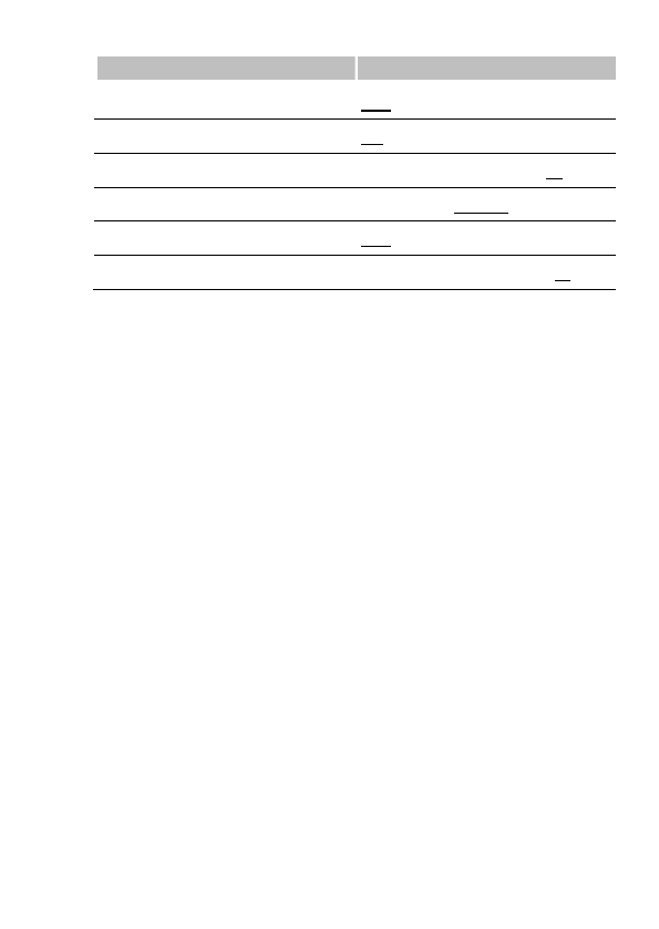
72 – US-ENGLISH
Special features
Values
Smoothing
OFF-Very slow-Slow-Medium-Fast
Mode Switch
ON-OFF
Mode Switch Rate (min-1)
From 30 to 90 by steps of 5; 60
Physical activity
Very low-Low-Medium-High-Very high
CRT optimisation
OFF- AV+VV
Exercise AV opt. rate (min-1)
From 70 to 120 by steps of 5; 90

US-ENGLISH – 73
Pacing/Sensing
Values
Atrial sensitivity (mV) (1)
From 0.2 to 4 by steps of 0.2; 0.4 (± 50 %)
Atrial amplitude (V) (2)
1-1.5-2-2.5-3-3.5-4-4.5-5-6 (± 20 %)
Atrial pulse width (ms)
0.12-0.25-0.35-0.5-0.6-0.75-0.85-1 (± 10 %)
Ventricular sensitivity (mV) (1)
From 0.4 to 4 by steps of 0.2; 0.4 (± 50 %)
RV amplitude (V) (2)
1-1.5-2-2.5-3-3.5-4-4.5-5-6 (± 20 %)
RV pulse width (ms)
0.12-0.25-0.35-0.5-0.6-0.75-0.85-1 (± 10 %)
LV amplitude (V) (2)
0.25 (± 50 %)
0.5-0.75- (± 30 %)
1-1.25-1.5-1.75-2-2.25-2.5-2.75-3-3.25-3.5-
3.75-4-4.25-4.5-4.75-5-6-7 (± 20 %)
LV pulse width (ms)
0.12-0.25-0.35-0.5-0.6-0.75-0.85-1 (± 10 %)
LV pacing polarity
LV bipolar-LV tip to RV-LV ring to RV coil
V chambers
Right-R+L-L+R
VV delay (ms)
0-8-16-24-32-40-48-56-64 (± 3 ms)
(1) Values are measured using a positive and negative triangular signal of
2/13 ms.
(2) The correlation between the programmed amplitudes, the stored
amplitudes and the mid-pulse delivered amplitudes under a 500 ohm load are
given in the following table:
Programmed ampl. (V)
0.25*
0.5*
0.75*
1
1.25*
1.5
Mid-pulse delivered ampl. (V)
0.28
0.49
0.76
0.97
1.18
1.39
Stored amplitude (V)
0.33
0.57
0.89
1.14
1.38
1.63
Programmed ampl. (V)
1.75*
2
2.25*
2.5
2.75*
3
Mid-pulse delivered ampl. (V)
1.66
1.79
2.08
2.35
2.56
2.84
Stored amplitude (V)
1.95
2.10
2.44
2.76
3.01
3.33
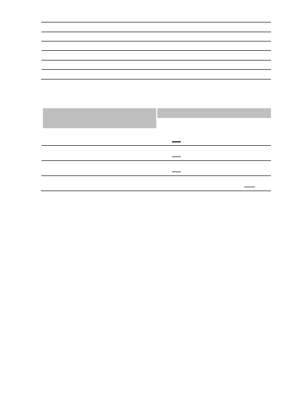
74 – US-ENGLISH
Programmed ampl. (V)
3.25*
3.5
3.75*
4
4.25*
4.5
Mid-pulse delivered ampl. (V)
3.05
3.25
3.39
3.58
3.88
4.23
Stored amplitude (V)
3.58
3.82
3.98
4.20
4.55
4.96
Programmed ampl. (V)
4.75*
5
6
7*
Mid-pulse delivered ampl. (V)
4.36
4.47
5.37
6.26
Stored amplitude (V)
5.12
5.25
6.30
7.35
* For left ventricular amplitude only.
Ventricular arrhythmia
prevention
Values
Atrial pacing on PVC
Yes-No
Post extrasystolic pause suppression
Yes-No
Acceleration on PVC
Yes-No
Max accelerated rate (min-1)
From 60 to 145 by steps of 5; 100

US-ENGLISH – 75
Post-shock mode
Values
Mode
OFF-VVI-DDI-DDD
Duration
10s-20s-30s-1min-2min-3min-4min-5min
Basic rate (min-1)
From 50 to 90 by steps of 5; 60 (± 4 %)
Rest AV delay (ms)
30-40-45-55-65-70-80-85-95-100-110-
115-125-135-140-150-155-165-170-180-
190-195-205-210-220-225-235-250
(± 19 ms)
Exercise AV delay (ms)
30-40-45-55-65-70-80-85-95-100-110-
115-125-135-140-150-155-165-170-180-
190-195-205-210-220-225-235-250
(± 19 ms)
AVD Paced/Sensed Offset (ms)
0-10-15-25-30-40-45-55-65-70-80-85-95-
100-110-115-125 (± 1 ms)
A amplitude (V)
1-1.5-2-2.5-3-3.5-4-4.5-5-6 (± 20 %)
A pulse width (ms)
0.12-0.25-0.35-0.5-0.6-0.75-0.85-1
(± 10 %)
RV amplitude (V)
1-1.5-2-2.5-3-3.5-4-4.5-5-6 (± 20 %)
RV pulse width (ms)
0.12-0.25-0.35-0.5-0.6-0.75-0.85-1
(± 10 %)
LV amplitude (V)
0.25- (± 50 %)
0.5-0.75- (± 30 %)
1-1.25-1.5-1.75-2-2.25-2.5-2.75-3-3.25-
3.5-3.75-4-4.25-4.5-4.75-5-6-7 (± 20 %)
LV pulse width (ms)
0.12-0.25-0.35-0.5-0.6-0.75-0.85-1
(± 10 %)
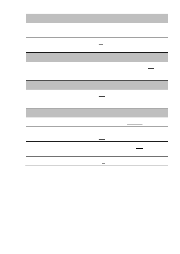
76 – US-ENGLISH
Refractory periods
Values
Atrial refractory period post ventricular
sensing (ms)
45-65-80-95-110-125-140-155
(± 16 ms)
Atrial refractory period post ventricular
pacing (ms)
80-95-110-125-140-155 (± 4 ms)
Sensitivity margins
Values
Atrial post pacing/sensing margin (mV)
From 0 to 1 by steps of 0.2; 0.4
Ventricular post pacing margin (mV)
From 0 to 2 by steps of 0.2; 0.8
Response to noise
Values
Automatic sensitivity on noise
ON-OFF
V pacing on noise
ON-OFF
SafeR (AAI <=> DDD) parameters
Values
AVB I switch
Rest+Exercise-Exercise
Long PR: max (ms)
80-100-125-150-200-250-300-350-400-
450-500
Long PR: min (ms)
80-100-125-150-200-250-300-350-400-
450-500
Max. pause (s)
2-3-4
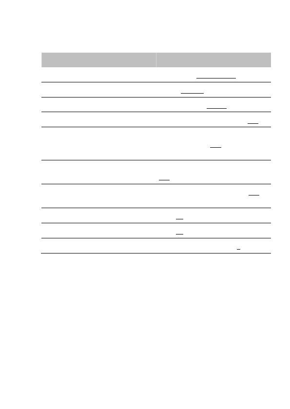
US-ENGLISH – 77
21.2. VENTRICULAR TACHYARRHYTHMIA
DETECTION
Therapy zones
Values
Slow VT detection zone (1)
Slow VT ON-Slow VT OFF
VT detection zone
VT ON-VT OFF
Fast VT / VF detection zone
Fast VT+VF ON-VF ON
Slow VT rate (lower limit) (min-1)
From 100 to 200 by steps of 5; 190
VT rate (lower limit) (min-1)
130-135-140-145-150-155-160-165-
170-175-180-185-190-195-200-210-
220-230
VF rate (lower limit) (min-1)
150-155-160-165-170-175-180-185-
190-195-200-210-220-230-240
Fast VT rate (upper limit) (min-1)
155-160-165-170-175-180-185-190-
195-200-210-220-230-240-255
Slow VT persistence (cycles)
4-6-8-12-16-20-30-50-100-200
VT persistence (cycles)
4-6-8-12-16-20-30-50-100-200
VF persistence (cycles)
From 4 to 20 by steps of 1; 6
(1) The Slow VT zone should be programmed ON only if the VT zone is
programmed ON.
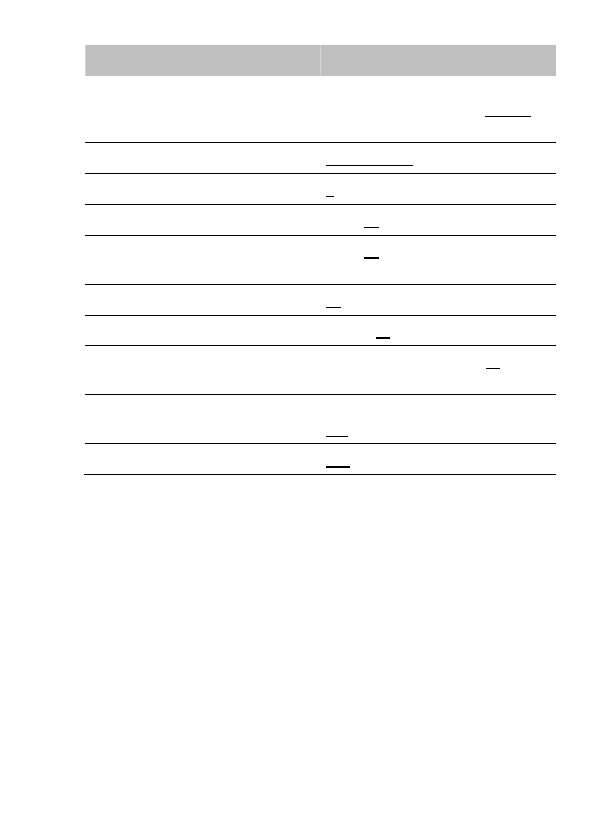
78 – US-ENGLISH
Detection criteria
Values
Slow VT and VT detection criteria
Rate Only-Stability-Stability+-
Stability/Acc-Stability+/Acc-PARAD-
PARAD+
Fast VT detection criteria
Rate+Stability-Rate Only
Majority: (X/Y), Y (cycles)
8-12-16
Majority: (X/Y), X (%)
65-70-75-80-90-95-100
Window of RR stability for Slow VT and
VT (ms)
30-45-65-80-95-110-125-125
Window of RR stability for fast VT (ms)
30-45-65
Prematurity acceleration (%)
6-13-19-25-31-38-44-50
Long cycle persistence extension
(cycles)
From 0 to 16 by steps of 1; 10
Long cycle gap (ms)
15-30-45-65-80-95-110-125-140-155-
170-190-205
Atrial monitoring
Yes-No

US-ENGLISH – 79
21.3. VENTRICULAR TACHYARRHYTHMIA
THERAPIES
Common parameters
Values
Enable ATP therapy
Yes-No
Enable shock therapy
Yes-No
ATP pacing chamber
Right-Left-R+L
Polarity alternation (42J)
Yes-No
Atrial coil (SVC) present
Yes-No
Active case
Yes-No
Shock configuration (+ --> -)
Case to RV-SVC to RV-Case + SVC to RV-RV
to Case-RV to SVC-RV to Case + SVC
SVC exclusion (shock < 15J)
Yes-No
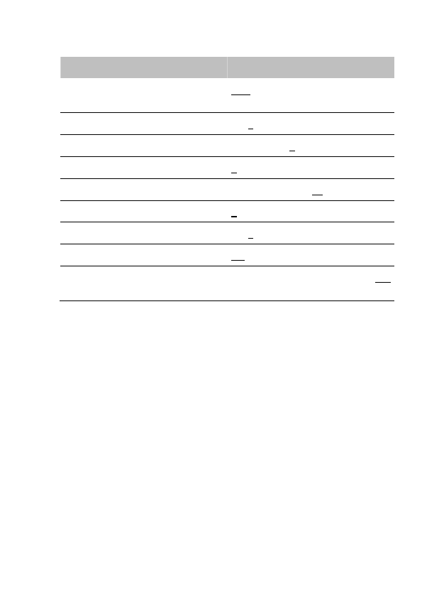
80 – US-ENGLISH
♦ Therapy parameters in slow VT zone
ATP 1 program
Values
ATP program
OFF-Burst-Burst+Scan-Ramp-
Ramp+Scan
Number of sequences
1-2-3-4-5-6-7-8-9-10-11-12-13-14-15
Cycles in first sequence
1-2-3-4-5-6-7-8-9-10-11-12-13-14-15
Cycles added per sequence
0-1-2-3-4-5-6-7-8-9-10-11-12-13-14-15
Coupling interval (%)
50-55-60-65-70-75-80-85-90-95
Ramp decrement (per cycle) (ms)
0-4-8-12-16-20-30-40-50-60
Scan decrement (per sequence) (ms)
0-4-8-12-16-20-30-40-50-60
Time limit (min)
0.5-1-1.5-2-2.5-3-3.5-4
Minimum cycle length (ms)
95-110-125-140-155-170-190-205-220-
235-250-265-280-295-310
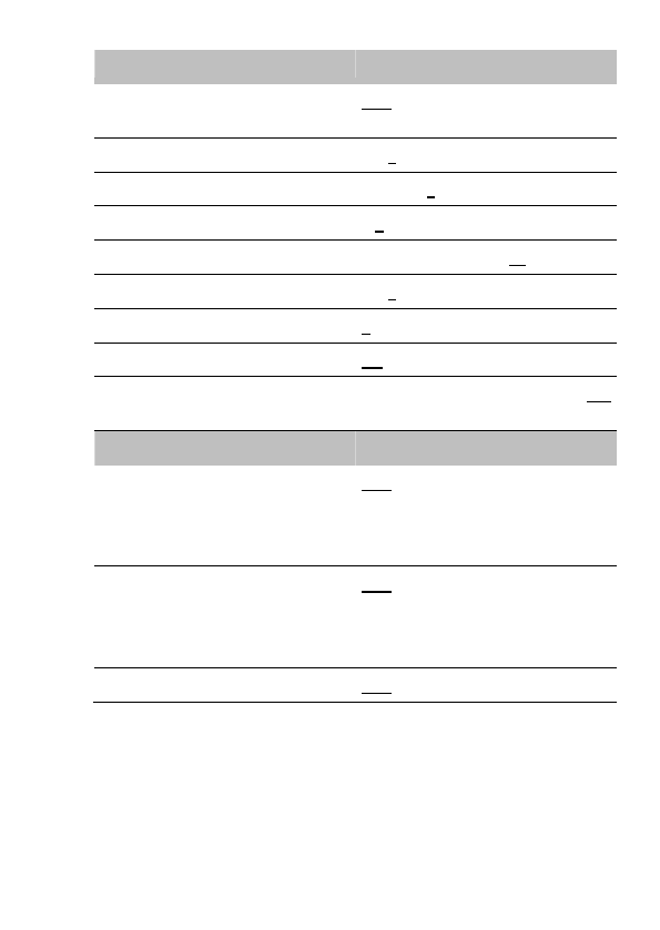
US-ENGLISH – 81
ATP 2 program
Values
ATP program
OFF-Burst-Burst+Scan-Ramp-
Ramp+Scan
Number of sequences
1-2-3-4-5-6-7-8-9-10-11-12-13-14-15
Cycles in first sequence
1-2-3-4-5-6-7-8-9-10-11-12-13-14-15
Cycles added per sequence
0-1-2-3-4-5-6-7-8-9-10-11-12-13-14-15
Coupling interval (%)
50-55-60-65-70-75-80-85-90-95
Ramp decrement (per cycle) (ms)
0-4-8-12-16-20-30-40-50-60
Scan decrement (per sequence) (ms)
0-4-8-12-16-20-30-40-50-60
Time limit (min)
0.5-1-1.5-2-2.5-3-3.5-4
Minimum cycle length (ms)
95-110-125-140-155-170-190-205-220-
235-250-265-280-295-310
Shock program
Values
Shock 1 (J)
OFF-0.5-0.8-1-1.3-1.5-2-2.5-3-3.5-4-5-
6-7-8-9- (± 30 %)
10-12-14-16-18-20-22-24-26-28-30-32-
34-42 (± 15 %)
Shock 2 (J)
OFF-0.5-0.8-1-1.3-1.5-2-2.5-3-3.5-4-5-
6-7-8-9- (± 30 %)
10-12-14-16-18-20-22-24-26-28-30-32-
34-42 (± 15 %)
Number of Max. Shock (42 J)
OFF-1-2-3-4
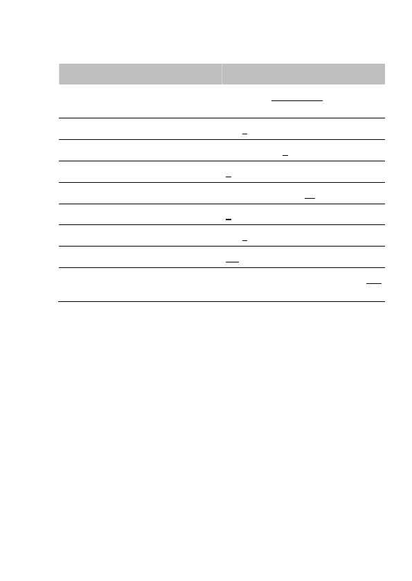
82 – US-ENGLISH
♦ Therapy parameters in VT zone
ATP 1 program
Values
ATP program
OFF-Burst-Burst+Scan-Ramp-
Ramp+Scan
Number of sequences
1-2-3-4-5-6-7-8-9-10-11-12-13-14-15
Cycles in first sequence
1-2-3-4-5-6-7-8-9-10-11-12-13-14-15
Cycles added per sequence
0-1-2-3-4-5-6-7-8-9-10-11-12-13-14-15
Coupling interval (%)
50-55-60-65-70-75-80-85-90-95
Ramp decrement (per cycle) (ms)
0-4-8-12-16-20-30-40-50-60
Scan decrement (per sequence) (ms)
0-4-8-12-16-20-30-40-50-60
Time limit (min)
0.5-1-1.5-2-2.5-3-3.5-4
Minimum cycle length (ms)
95-110-125-140-155-170-190-205-220-
235-250-265-280-295-310
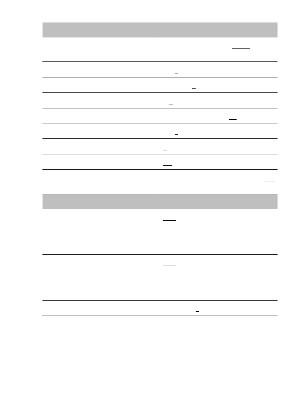
US-ENGLISH – 83
ATP 2 program
Values
ATP program
OFF-Burst-Burst+Scan-Ramp-
Ramp+Scan
Number of sequences
1-2-3-4-5-6-7-8-9-10-11-12-13-14-15
Cycles in first sequence
1-2-3-4-5-6-7-8-9-10-11-12-13-14-15
Cycles added per sequence
0-1-2-3-4-5-6-7-8-9-10-11-12-13-14-15
Coupling interval (%)
50-55-60-65-70-75-80-85-90-95
Ramp decrement (per cycle) (ms)
0-4-8-12-16-20-30-40-50-60
Scan decrement (per sequence) (ms)
0-4-8-12-16-20-30-40-50-60
Time limit (min)
0.5-1-1.5-2-2.5-3-3.5-4
Minimum cycle length (ms)
95-110-125-140-155-170-190-205-220-
235-250-265-280-295-310
Shock program
Values
Shock 1 (J)
OFF-0.5-0.8-1-1.3-1.5-2-2.5-3-3.5-4-5-
6-7-8-9- (± 30 %)
10-12-14-16-18-20-22-24-26-28-30-32-
34-42 (± 15 %)
Shock 2 (J)
OFF-0.5-0.8-1-1.3-1.5-2-2.5-3-3.5-4-5-
6-7-8-9- (± 30 %)
10-12-14-16-18-20-22-24-26-28-30-32-
34-42 (± 15 %)
Number of Max. Shock (42 J)
OFF-1-2-3-4
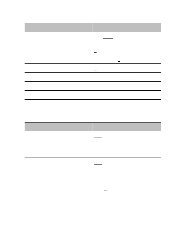
84 – US-ENGLISH
♦ Therapy parameters in fast VT / VF zone
ATP 1 program
Values
ATP program
OFF-Burst-Burst+Scan-Ramp-
Ramp+Scan
Number of sequences
1-2-3-4-5-6-7-8-9-10-11-12-13-14-15
Cycles in first sequence
1-2-3-4-5-6-7-8-9-10-11-12-13-14-15
Cycles added per sequence
0-1-2-3-4-5-6-7-8-9-10-11-12-13-14-15
Coupling interval (%)
50-55-60-65-70-75-80-85-90-95
Ramp decrement (per cycle) (ms)
0-4-8-12-16-20-30-40-50-60
Scan decrement (per sequence) (ms)
0-4-8-12-16-20-30-40-50-60
Time limit
10s-20s-30s-1min-1.5min-2min
Minimum cycle length (ms)
95-110-125-140-155-170-190-205-220-
235-250-265-280-295-310
Shock program
Values
Shock 1 (J)
OFF-0.5-0.8-1-1.3-1.5-2-2.5-3-3.5-4-5-
6-7-8-9- (± 30 %)
10-12-14-16-18-20-22-24-26-28-30-32-
34-42 (± 15 %)
Shock 2 (J)
OFF-0.5-0.8-1-1.3-1.5-2-2.5-3-3.5-4-5-
6-7-8-9- (± 30 %)
10-12-14-16-18-20-22-24-26-28-30-32-
34-42 (± 15 %)
Number of Max. Shock (42 J)
1-2-3-4
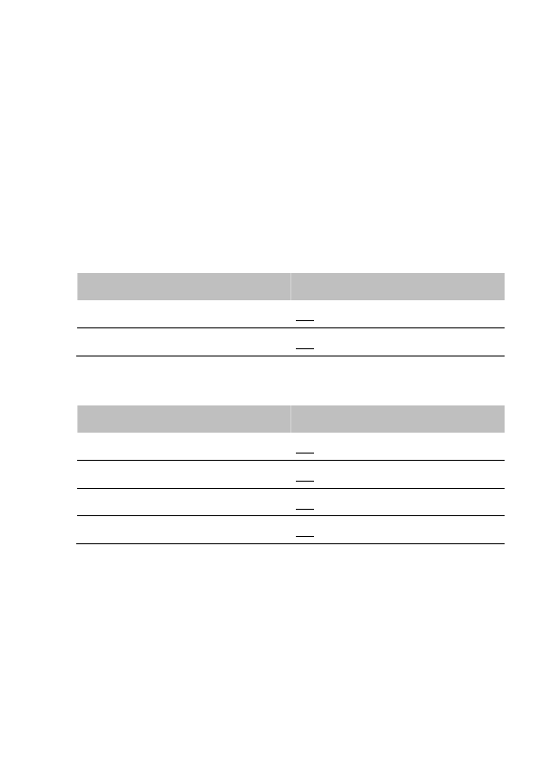
US-ENGLISH – 85
21.4. REMOTE ALERTS AND WARNINGS
The device routinely performs security self-checks and technical
measurements to ensure system integrity. When system integrity is
found to be at risk outside a follow-up, alerts are stored in the device
memory. When system integrity is found to be at risk during a follow-
up, the information is managed as a warning (pop-up message) to
notify immediately the user. For example, the following types of event
can trigger a warning or an alert: technical problem during a shock,
pacing lead impedance or coil impedance measurements out-of-
range, battery depletion, etc. The Remote tab presents an overview
of all the alerts managed by the device.
General parameters
Values
RF communication (1)
ON-OFF
Remote alerts (1)
ON-OFF
(1) RF and Remote alerts are turned on automatically if Shocks are
programmed ON.
System Alerts
Values
Battery depletion – ERI
ON-OFF
Device reset
ON-OFF
Excessive charge time (>25s)
ON-OFF
System integrity
ON-OFF
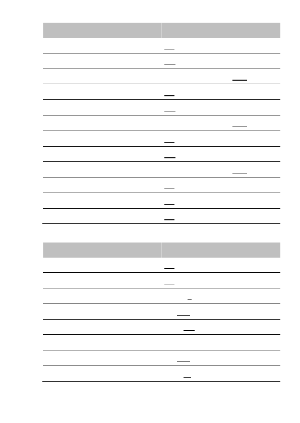
86 – US-ENGLISH
Lead Alerts
Values
Abnormal A lead impedance
ON-OFF
Abnormal A lead low limit (Ohm)
200-250-300-350-400-450-500
Abnormal A lead high limit (Ohm)
1500-1750-2000-2500-3000
Abnormal RV lead impedance
ON-OFF
Abnormal RV lead low limit (Ohm)
200-250-300-350-400-450-500
Abnormal RV lead high limit (Ohm)
1500-1750-2000-2500-3000
Abnormal LV lead impedance
ON-OFF
Abnormal LV lead low limit (Ohm)
200-250-300-350-400-450-500
Abnormal LV lead high limit (Ohm)
1500-1750-2000-2500-3000
Abnormal RV coil impedance
ON-OFF
Abnormal SVC coil impedance
ON-OFF
Abnormal Shock impedance (1)
ON-OFF
(1) Normal impedance range [20 Ohm-200 Ohm]
Clinical status
Values
V oversensing
ON-OFF
High AT/AF burden
ON-OFF
AT/AF limit (on 24h) (h)
0.5-1-3-6-12-24
Fast V Rate during AT/AF
ON-OFF
Fast V Rate limit (min-1)
80-90-100-110-120
Fast V Duration limit (h)
0.5-1-3-6-12-24
Limited % of V pacing in CRT
ON-OFF
Limited % of V pacing (%)
50-70-80-85-90-95

US-ENGLISH – 87
Therapy information
Values
Shock disabled
ON-OFF
Shocks delivered
OFF-All shocks-Inefficient shock-
Inefficient max shock
88 – US-ENGLISH
22. NON PROGRAMMABLE PARAMETERS
Interval
Values
Committed period
95 ms (± 5 ms)
Atrial refractory periods
Values
Post atrial sensing
47 ms (± 16 ms)
Post atrial pacing
109 ms (± 4 ms)
Ventricular refractory periods
Values
Post ventricular sensing
95 ms (± 16 ms)
Post ventricular pacing
220 ms (± 4 ms)
Post atrial pacing (blanking)
16 ms (± 3 ms)
Tachycardia criteria
Values
Window of PR association
63 ms (± 1 ms)
Therapies
Values
Waveform
Constant tilt (50% - 50%)
Stored energy for the Max. shock
42 J (± 15 %)
Pacing amplitude during ATP therapies
7 V (Actual value at 300 ms: 5.3 V)
Anti-PMT protection
Termin

US-ENGLISH – 89
23. LIMITED WARRANTY
The PARADYM RF implantable cardioverter defibrillator is the result
of highly advanced research and all components have been selected
after exhaustive testing.
Sorin CRM S.r.l. (identified as “Sorin CRM” hereafter) guarantees the
product PARADYM RF against any damage caused by component
failure or production defects during a period of four years after the
implantation date, and Sorin CRM commits itself to replace all
PARADYM RF devices according to the terms described in article 1
and described in article 2 of this section.
Sorin CRM makes no claim that the human body will not react unsuitably
to the implantation of the PARADYM RF device, or that failure will never
occur.
Sorin CRM does not guarantee the suitability of PARADYM RF in
defined types of patients: selection of the device is a medical
decision.
Sorin CRM shall not be held liable for any damage indirectly
associated with the PARADYM RF, whether as part of normal or
abnormal operation, nor damage from its explantation or
replacement.
Sorin CRM does not authorise anyone to modify these limited
warranty conditions.

90 – US-ENGLISH
23.1. ARTICLE 1: TERMS OF LIMITED WARRANTY
1. The PARADYM RF implantable cardioverter defibrillator is only
guaranteed for the first implantation.
2. The EURID/IAPM implant form must be sent to Sorin CRM within
30 days after implantation.
3. The PARADYM RF cardioverter defibrillator must be implanted
prior to the use-before date indicated on the packaging.
4. The limited guarantee only applies to suspect devices returned to
the manufacturer, carefully packed and accompanied by an
explantation report duly completed by the hospital or the doctor
and considered defective after analysis by Sorin CRM.
The device must be returned within the 30 days following
explantation to Sorin CRM.
Any device returned and replaced under the terms of this limited
warranty will become the exclusive property of Sorin CRM.
Any rights under the terms of this limited warranty will be forfeited
if the PARADYM RF device has been opened by anyone other
than Sorin CRM.
These rights will also be forfeited if the device has been
damaged by carelessness or accident.
This is the case especially if the device has been exposed to
temperatures above 50°C, to electrical abuse or to mechanical
shock, particularly as a result of being dropped. Consequently,
any expert opinion offered by a third party after the device has
been removed also nullifies the guarantee.
5. The limited warranty will be forfeited if it is proven that the device
has been misused or inadequately implanted, against the
physicians’manual recommendations of PARADYM RF.
6. The limited warranty does not include leads and other
accessories used for the implantation.

US-ENGLISH – 91
7. The replacement terms or conditions described in article 2
include all devices that shall be replaced within the limited
warranty period because of battery depletion, without any link to
a component failure or a production hazard. The device battery
longevity varies with the type and number of delivered therapies.
8. Legal requirements of jurisdictions where the PARADYM RF
device is distributed will supersede any warranty conditions
indicated in this manual that conflict with such laws.

92 – US-ENGLISH
23.2. ARTICLE 2: TERMS OF REPLACEMENT
1. In case of PARADYM RF failure because of a component failure,
a production defect, or a conception error, occurring within two-
year period starting from the implantation date, Sorin CRM is
committed to:
― replacing free of charge the explanted device by a Sorin
CRM device with equivalent features,
― or issuing a replacement credit equal to the purchase
price for the purchase of any other Sorin CRM
replacement device.
2. After a two-year period and up to 4 years after the implantation,
Sorin CRM, because of limited warranty terms, will issue a
replacement credit to the buyer of an amount equivalent to half
of the initial purchase price minus prorata temporis during this
two-years period.
3. In any case the credit issued by the limited warranty terms
cannot exceed the purchase price of a Sorin CRM replacement
device.

US-ENGLISH – 93
24. PATENTS
The PARADYM RF model described in this manual is covered by the
following US patents:
5 167 224, 5 226 415, 5 271 394, 5 312 451, 5 325 856, 5 339 820,
5 350 406, 5 411 533, 5 462 060, 5 513 645, 5 545 181, 5 558 097,
5 564 430, 5 591 218, 5 626 619, 5 645 574, 5 674 265, 5 697 960,
5 702 424, 5 702 426, 5 713 928, 5 741 315, 5 776 164, 5 776 165,
5 818 703, 5 836 980, 5 868 793, 5 891 170, 5 891 184, 5 899 931,
5 931 856, 5 935 153, 5 954 660, 5 978 708, 6 181 968, 6 230 058,
6 236 111, 6 251 703, 6 256 206, 6 307 261, 6 337 996, 6 397 105,
6 408 209, 6 487 451, 6 487 452, 6 505 068, 6 532 238, 6 556 866,
6 604 002, 6 622 039, 6 625 491, 6 711 441, 6 738 665, 6 830 548,
6 889 080, 6 898 845, 6 912 421, 6 937 898, 6 975 905, 7 065 402,
7 072 716, 7 076 297, 7 113 826, 7 142 924, 7 164 946, 7 251 526,
7 366 566, 7 400 921, 7 400 922, 7 953 483.
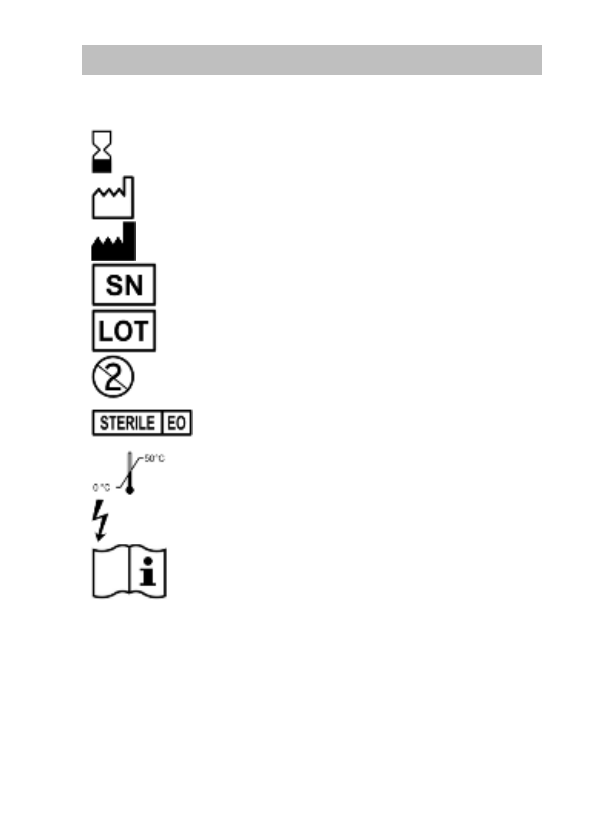
94 – US-ENGLISH
25. EXPLANATION OF SYMBOLS
The symbols on product labelling have the following meaning:
Use by
Date of Manufacturer
Manufacturer
Serial number
Batch number
For single use only.
Sterilised using ethylene oxide
Temperature limitation
High voltage
Consult instruction for use.
FCC ID YSGCRTDSONR9770
IC : 10270A-CRTDSON9770
Last revision date of this implant manual: 2012-05