SPAL USA AIRRX air kit (rx) User Manual users manual
SPAL USA air kit (rx) users manual
UserManual.wiki
>
SPAL USA
>
AIRRX User Manual
users manual
Navigation menu
Upload a User Manual
Namespaces
Wiki Guide
HTML
PDF
Info
Views
User Manual
Discussion / Help
Navigation
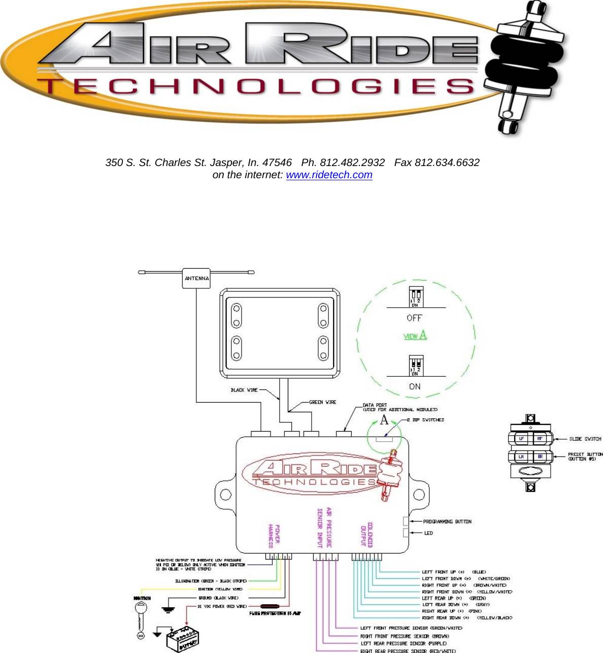
![Connector # 1 – Power harness •Connect green/black stripe to----------------- illumination •Connect yellow to-------------------------------- ignition •Connect black to----------------------------------directly to ground of battery •Connect red to------------------------------------ directly to battery 12v positive Connector # 2 – Sensor harness •Connect green/white wire to------------------ left front pressure sensor •Connect brown wire to------------------------- right front pressure sensor •Connect purple wire to------------------------- left rear pressure sensor •Connect red/white wire to--------------------- right rear pressure sensor Connector # 3 – Solenoid harness NOTE: This harness will have a weatherpak connector on it that will plug in to our existing RidePro solenoids. There will be no further connections necessary. If you have another brand or type of solenoid, please refer to the connection instructions below for proper connection. •Connect blue wire to -------------------------- left front UP solenoid •Connect white/green wire to----------------- left front DOWN solenoid •Connect brown/white wire to---------------- right front UP solenoid •Connect yellow/white wire to----------------right front DOWN solenoid •Connect green wire to------------------------ left rear UP solenoid •Connect gray wire to--------------------------left rear DOWN solenoid •Connect pink wire to---------------------------right rear UP solenoid •Connect yellow/black wire to--------------- right rear DOWN solenoid Installation notes: 1. The computer box should be mounted inside the vehicle to avoid moisture and to be accessible to make programming changes. DO NOT MOUNT THE COMPUTER BOX IN THE ENGINE BAY OR UNDERNEATH THE CAR. 2. Do not plug in the receiver module until all the wiring is complete. 3. The air pressure sending units must be grounded to function properly. This can be accomplished through a metal mounting bracket or by attaching a ground wire to the main body of the sensor. 4. The control panel display unit can be flush mounted or surface mounted in any location inside the vehicle…or it can be left unmounted. It is supplied with 6 ft. leads to the computer box. 12 ft. leads are available from the factory if desired. DO NOT lengthen or shorten these leads…call the factory for a longer harness. 5. The control panel is an LCD display. This display may be unsatisfactory if mounted at an extreme angle to the driver. You may want to power up the system temporarily to insure you are able to see the display properly in your selected mounting location. How to program the air pressure presets: To Program air pressure preset #1: This is the default setting that will be engaged every time the vehicle is started. It can also be engaged via the [optional] keyfob transmitter by placing the slide switch in the “up” position. It is recommended that this air pressure be adjusted to the highway ride height of the vehicle. 1. Place the DIP-switches located on the side of the computer box in the OFF [“up”] position 2.Turn ignition ON 3. Set desired air pressure of the vehicle with main control panel switches 4. Press the “program” button, located on the side of the computer box 6 times, (If the program button is held for 3 seconds on the 7th press of the button, level one will be set.) … the led beside the program button will then flash (4 Times) to indicate programming was successful.](https://usermanual.wiki/SPAL-USA/AIRRX/User-Guide-421326-Page-2.png)
![OPTIONAL: If you have the optional remote control system, set the slide switch on the side of the transmitter to the “UP” position and press the #5 button on the side of the keyfob transmitter to enter the #1 setting into the remote control system. The main control panel display will flash slowly four times to indicate remote control setting #1 was successful. After ALL programming is complete, return the DIP switches to the “ON” position to activate the air pressure presets. To Program air pressure setting #2: This air pressure preset is only accessible from the optional remote control keyfob transmitter. This air pressure setting is typically adjusted to set the vehicle at a lower ride height for parking. 1. Place the DIP-switches located on the side of the computer box in the OFF [“up”] position 2.Turn ignition ON 3. Set desired air pressure of the vehicle with main control panel switches 4. Press the “program” button, located on the side of the computer box 6 times … the led beside the program button will then flash. 5. Set the slide switch on the side of the transmitter to the “DOWN” position and press the #5 button on the side of the keyfob transmitter to enter the #2 setting into the remote control system. The main control panel display will flash quickly four times to indicate remote control setting #2 was successful. After ALL programming is complete, return the DIP-switches to the “ON” position to activate the air pressure presets. NOTE: The vehicle will return to the #1 air pressure preset every time the vehicle is started. If you DO NOT wish to use the air pressure preset feature, simply leave the DIP switches in the “OFF” [UP] position. How to operate the RidePro E system The main control panel display contains the switches for inflating or deflating the individual airsprings. The position of the switches correspond to the position of the airsprings in your vehicle. NOTE: The control panel is functional ONLY when the key is “ON”. It is disabled when the key is “OFF”. The optional remote control system is functional ONLY when the key is “OFF”. Control Panel: Top Left Switch: Controls left front ride height UP or DOWN Indicates Air Pressure of left front air bag Top Right Switch: Controls right front ride height UP or DOWN Indicates Air Pressure of right front air bag Bottom Left Switch: Controls left rear ride height UP or DOWN Indicates Air Pressure of left rear air bag Bottom Right Switch: Controls right rear ride height UP or DOWN Indicates Air Pressure of right rear air bag Optional Remote Control Transmitter: Button 1 (LF): Controls left front ride height UP or DOWN Button 2 (RF): Controls right front ride height UP or DOWN Button 3 (LR): Controls left rear ride height UP or DOWN Button 4 (RR): Controls right rear ride height UP or DOWN Button 5 (side of transmitter): Activates air pressure presets Slide Switch UP: Controls buttons 1-4 ride height UP and controls level #1 setting Slide Switch DOWN: Controls buttons 1-4 ride height DOWN and controls level # 2 setting](https://usermanual.wiki/SPAL-USA/AIRRX/User-Guide-421326-Page-3.png)