SRAM BOXED eTap System, Blip Box User Manual Red eTap Blip BlipBox
SRAM LLC. eTap System, Blip Box Red eTap Blip BlipBox
SRAM >
Contents
- 1. eTap Systems Manual
- 2. Red eTap Blip BlipBox_User Manual
Red eTap Blip BlipBox_User Manual

95-XXXX-XXX-XXX Rev X
© 2015 SRAM, LLC
Blips and BlipBoxTM
Blips/BlipBox
TM
User Manual Manuel d’entretien
Blips/BlipBox
TM
Manual do Utilizador
do Blips/BlipBox
TM
Blips/BlipBox
TM
Bedienungsanleitung Manuale dell'Utente
Blip/BlipBox
TM
Blips/BlipBox
TM
ユーザー ・ マニュアル
Manual de usuario
Blips/BlipBox
TM
Blips/BlipBox
TM
Gebruiksaanwijzing Blips/BlipBox
TM
用户手册
3
2.5 T25 2.5 T25
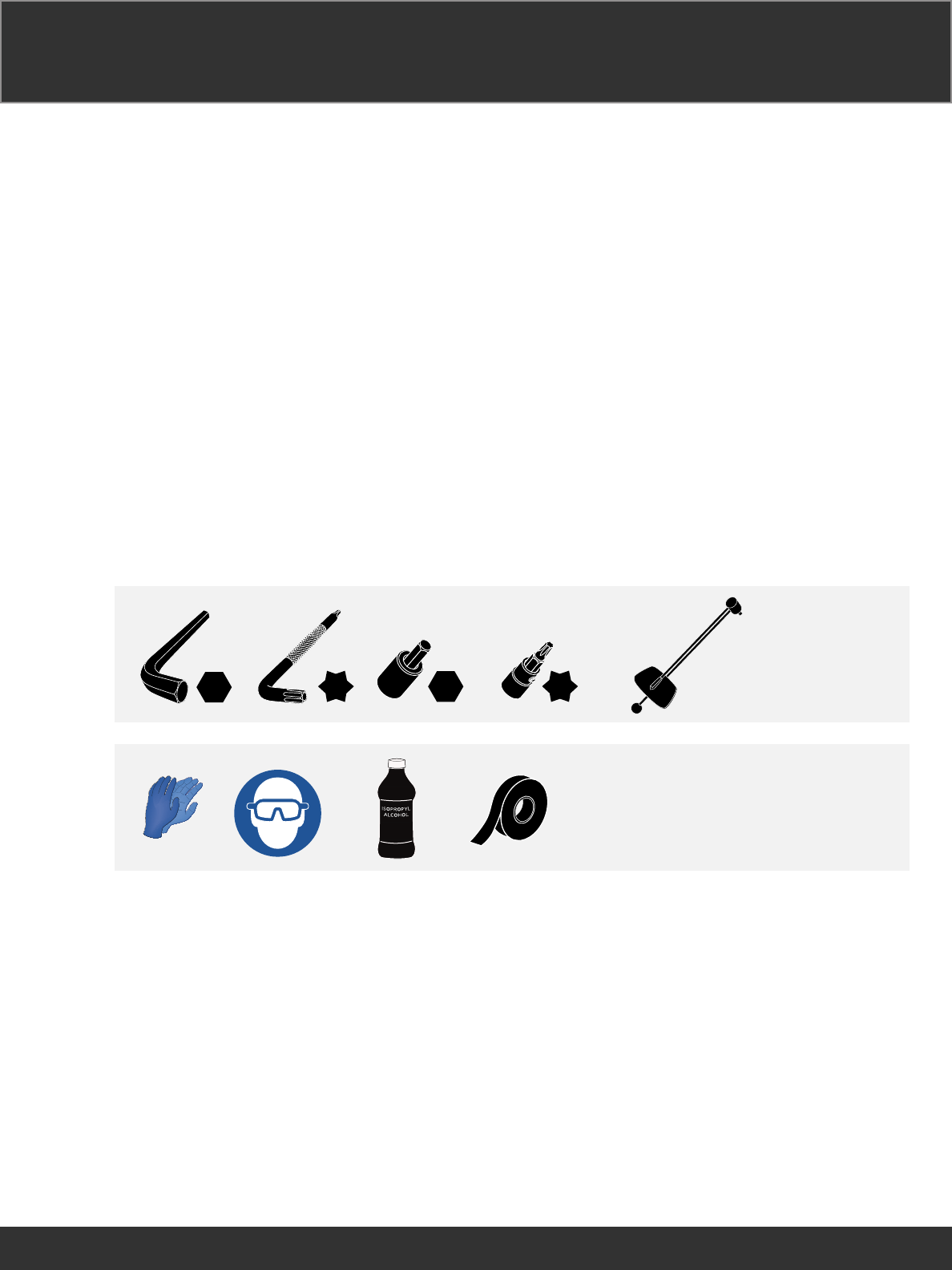
Highly specialized tools and supplies
are required for the installation
of your SRAM components. We
recommend that you have a qualified
bicycle mechanic install your SRAM
components.
Highly specialized tools and supplies
are required for the installation
of your SRAM components. We
recommend that you have a qualified
bicycle mechanic install your SRAM
components.
Highly specialized tools and supplies
are required for the installation
of your SRAM components. We
recommend that you have a qualified
bicycle mechanic install your SRAM
components.
Highly specialized tools and supplies
are required for the installation
of your SRAM components. We
recommend that you have a qualified
bicycle mechanic install your SRAM
components.
Highly specialized tools and supplies
are required for the installation
of your SRAM components. We
recommend that you have a qualified
bicycle mechanic install your SRAM
components.
Highly specialized tools and supplies
are required for the installation
of your SRAM components. We
recommend that you have a qualified
bicycle mechanic install your SRAM
components.
Highly specialized tools and supplies
are required for the installation
of your SRAM components. We
recommend that you have a qualified
bicycle mechanic install your SRAM
components.
Highly specialized tools and supplies
are required for the installation
of your SRAM components. We
recommend that you have a qualified
bicycle mechanic install your SRAM
components.
Highly specialized tools and supplies
are required for the installation
of your SRAM components. We
recommend that you have a qualified
bicycle mechanic install your SRAM
components.
Tools and Supplies Tools and Supplies Tools and Supplies
Tools and Supplies Tools and Supplies Tools and Supplies
Tools and Supplies Tools and Supplies Tools and Supplies

4
SAFETY INSTRUCTIONS
You must read and understand
the safety and warranty document
before proceeding with installation.
Improperly installed components
are extremely dangerous and could
result in severe and/or fatal injuries.
If you have any questions about the
installation of these components,
consult a qualified bicycle mechanic.
This document is also available on
www.sram.com.

5
Product Registration Product Registration Product Registration
Product Registration Product Registration Product Registration
Product Registration Product Registration Product Registration
For software updates and information
related to your products, please
register online at www.sram.com/
registration.
For software updates and information
related to your products, please
register online at www.sram.com/
registration.
For software updates and information
related to your products, please
register online at www.sram.com/
registration.
For software updates and information
related to your products, please
register online at www.sram.com/
registration.
For software updates and information
related to your products, please
register online at www.sram.com/
registration.
For software updates and information
related to your products, please
register online at www.sram.com/
registration.
For software updates and information
related to your products, please
register online at www.sram.com/
registration.
For software updates and information
related to your products, please
register online at www.sram.com/
registration.
For software updates and information
related to your products, please
register online at www.sram.com/
registration.
6
BlipBoxTM BlipBoxTM BlipBoxTM
BlipBoxTM BlipBoxTM BlipBoxTM
BlipBoxTM BlipBoxTM BlipBoxTM
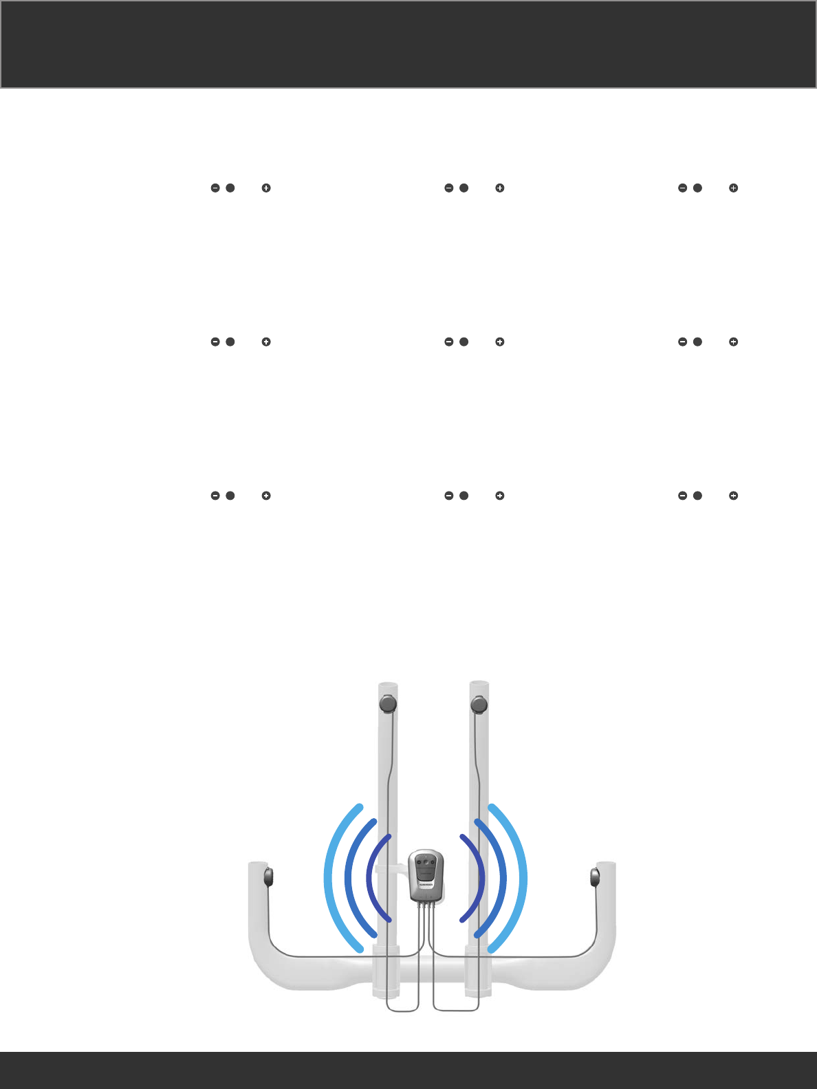
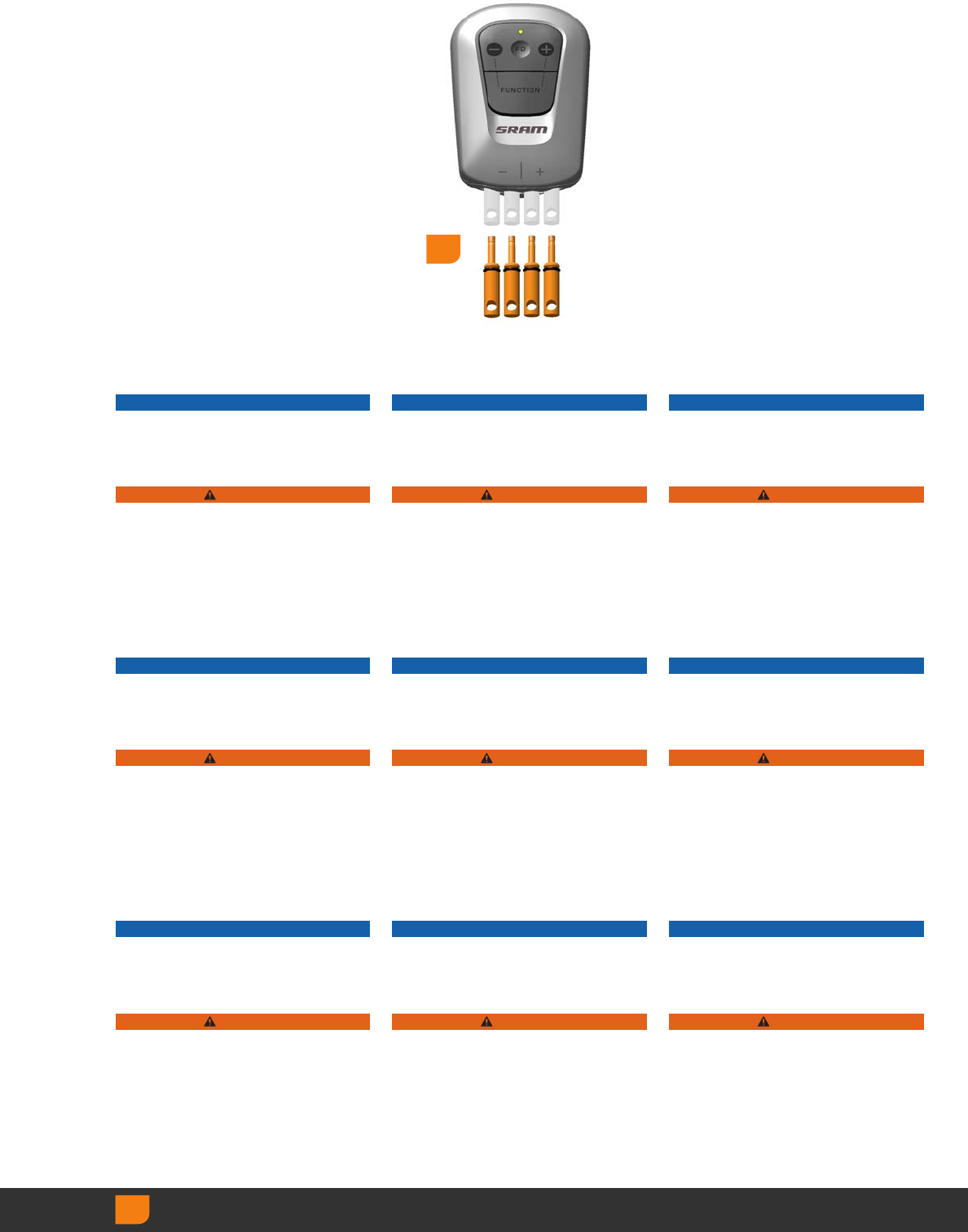
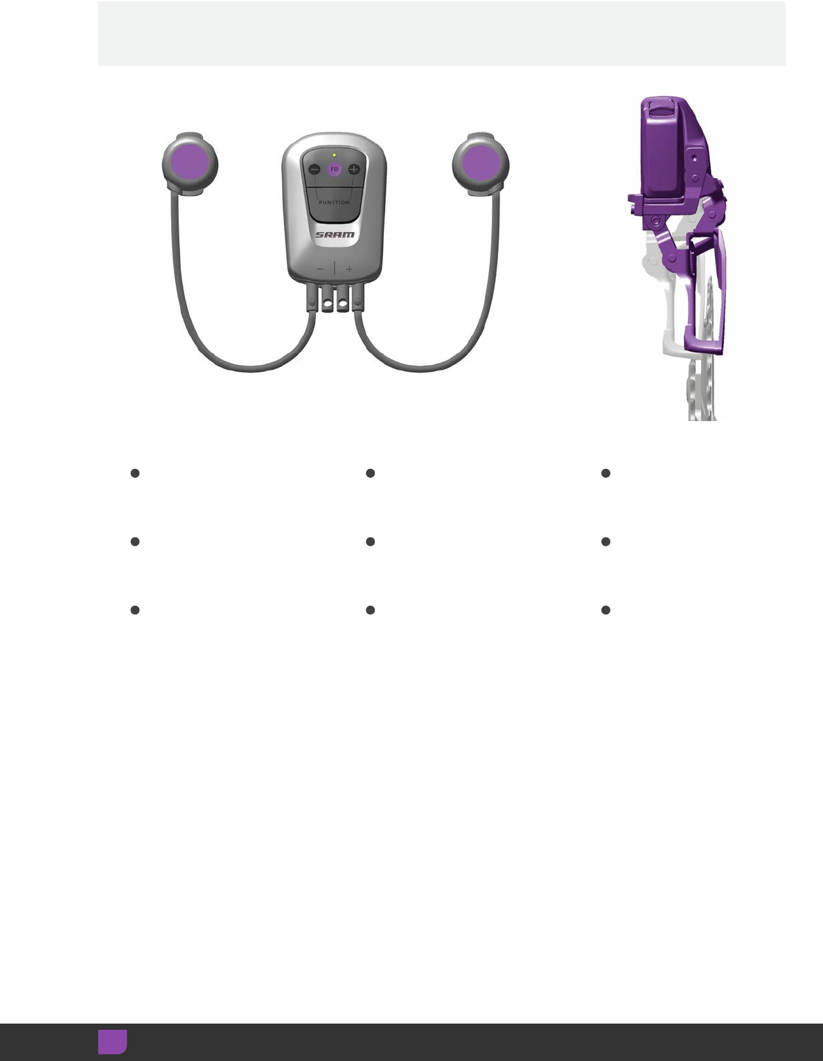
The BlipBox wirelessly pairs to each
derailleur, sends shift signals to the
front and rear derailleurs when the
Blips are pressed, and shifts the
derailleurs when the , FD and
buttons are pressed. The BlipBox is not
required when the Blips are connected
to eTap™ road shifters.
The BlipBox wirelessly pairs to each
derailleur, sends shift signals to the
front and rear derailleurs when the
Blips are pressed, and shifts the
derailleurs when the , FD and
buttons are pressed. The BlipBox is not
required when the Blips are connected
to eTap™ road shifters.
The BlipBox wirelessly pairs to each
derailleur, sends shift signals to the
front and rear derailleurs when the
Blips are pressed, and shifts the
derailleurs when the , FD and
buttons are pressed. The BlipBox is not
required when the Blips are connected
to eTap™ road shifters.
The BlipBox wirelessly pairs to each
derailleur, sends shift signals to the
front and rear derailleurs when the
Blips are pressed, and shifts the
derailleurs when the , FD and
buttons are pressed. The BlipBox is not
required when the Blips are connected
to eTap™ road shifters.
The BlipBox wirelessly pairs to each
derailleur, sends shift signals to the
front and rear derailleurs when the
Blips are pressed, and shifts the
derailleurs when the , FD and
buttons are pressed. The BlipBox is not
required when the Blips are connected
to eTap™ road shifters.
The BlipBox wirelessly pairs to each
derailleur, sends shift signals to the
front and rear derailleurs when the
Blips are pressed, and shifts the
derailleurs when the , FD and
buttons are pressed. The BlipBox is not
required when the Blips are connected
to eTap™ road shifters.
The BlipBox wirelessly pairs to each
derailleur, sends shift signals to the
front and rear derailleurs when the
Blips are pressed, and shifts the
derailleurs when the , FD and
buttons are pressed. The BlipBox is not
required when the Blips are connected
to eTap™ road shifters.
The BlipBox wirelessly pairs to each
derailleur, sends shift signals to the
front and rear derailleurs when the
Blips are pressed, and shifts the
derailleurs when the , FD and
buttons are pressed. The BlipBox is not
required when the Blips are connected
to eTap™ road shifters.
The BlipBox wirelessly pairs to each
derailleur, sends shift signals to the
front and rear derailleurs when the
Blips are pressed, and shifts the
derailleurs when the , FD and
buttons are pressed. The BlipBox is not
required when the Blips are connected
to eTap™ road shifters.
7
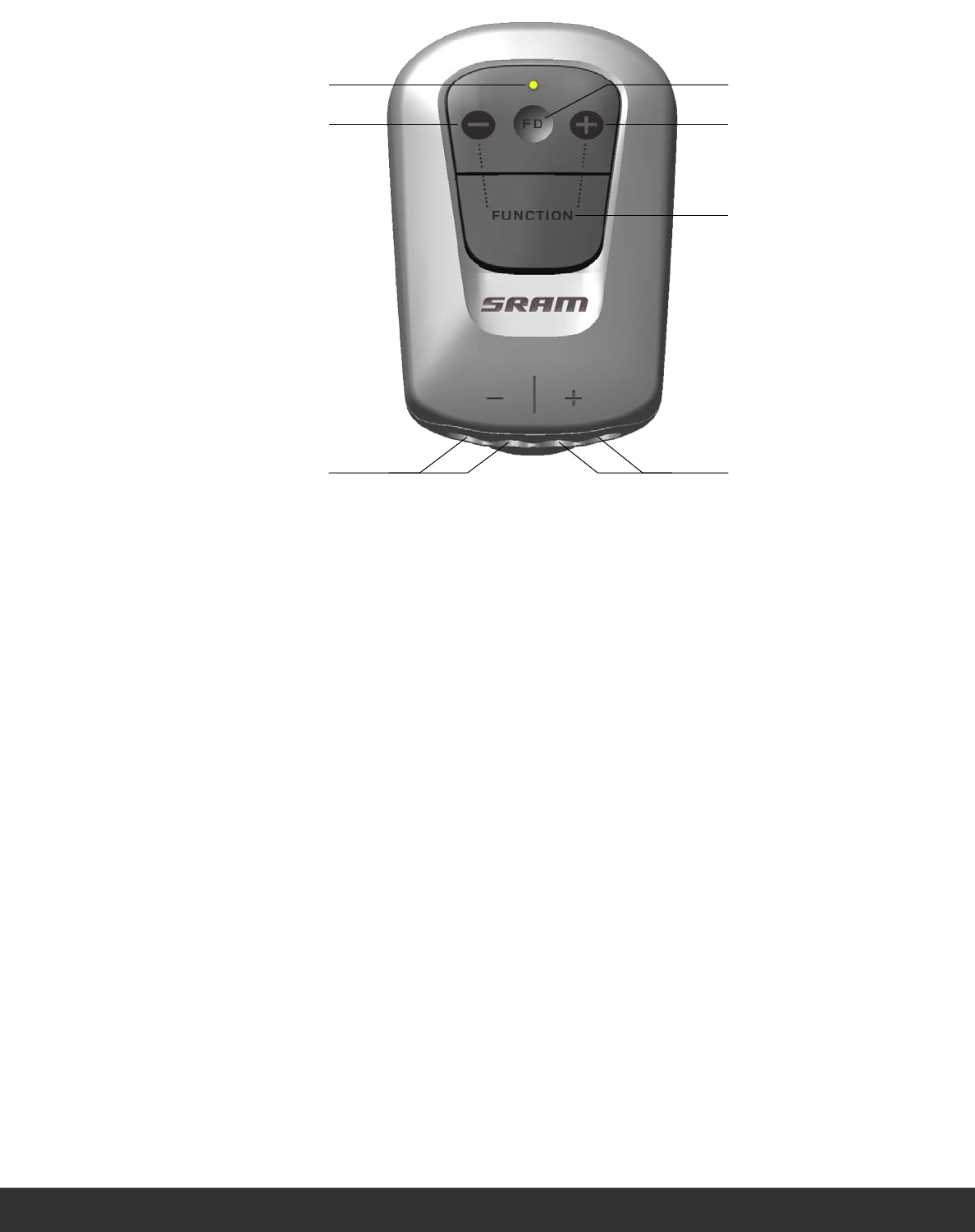
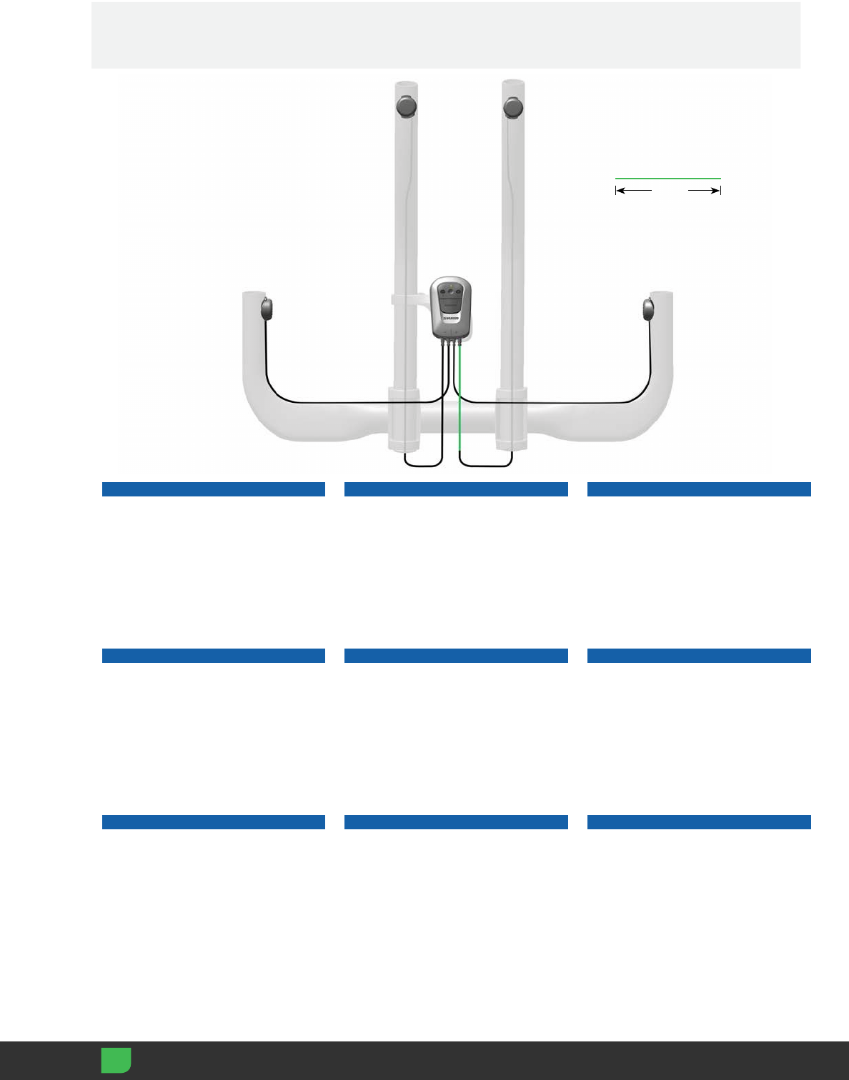
(a) LED
(b) Rear derailleur inboard shift
(c) Rear derailleur outboard shift
(d) Front derailleur shift
(e) Pairs BlipBox to each derailleur
(f) Wire input, left Blips
(g) Wire input, right Blips
(a) LED
(b) Rear derailleur inboard shift
(c) Rear derailleur outboard shift
(d) Front derailleur shift
(e) Pairs BlipBox to each derailleur
(f) Wire input, left Blips
(g) Wire input, right Blips
(a) LED
(b) Rear derailleur inboard shift
(c) Rear derailleur outboard shift
(d) Front derailleur shift
(e) Pairs BlipBox to each derailleur
(f) Wire input, left Blips
(g) Wire input, right Blips
(a) LED
(b) Rear derailleur inboard shift
(c) Rear derailleur outboard shift
(d) Front derailleur shift
(e) Pairs BlipBox to each derailleur
(f) Wire input, left Blips
(g) Wire input, right Blips
(a) LED
(b) Rear derailleur inboard shift
(c) Rear derailleur outboard shift
(d) Front derailleur shift
(e) Pairs BlipBox to each derailleur
(f) Wire input, left Blips
(g) Wire input, right Blips
(a) LED
(b) Rear derailleur inboard shift
(c) Rear derailleur outboard shift
(d) Front derailleur shift
(e) Pairs BlipBox to each derailleur
(f) Wire input, left Blips
(g) Wire input, right Blips
(a) LED
(b) Rear derailleur inboard shift
(c) Rear derailleur outboard shift
(d) Front derailleur shift
(e) Pairs BlipBox to each derailleur
(f) Wire input, left Blips
(g) Wire input, right Blips
(a) LED
(b) Rear derailleur inboard shift
(c) Rear derailleur outboard shift
(d) Front derailleur shift
(e) Pairs BlipBox to each derailleur
(f) Wire input, left Blips
(g) Wire input, right Blips
(a) LED
(b) Rear derailleur inboard shift
(c) Rear derailleur outboard shift
(d) Front derailleur shift
(e) Pairs BlipBox to each derailleur
(f) Wire input, left Blips
(g) Wire input, right Blips
gf
a
b c
d
e
8
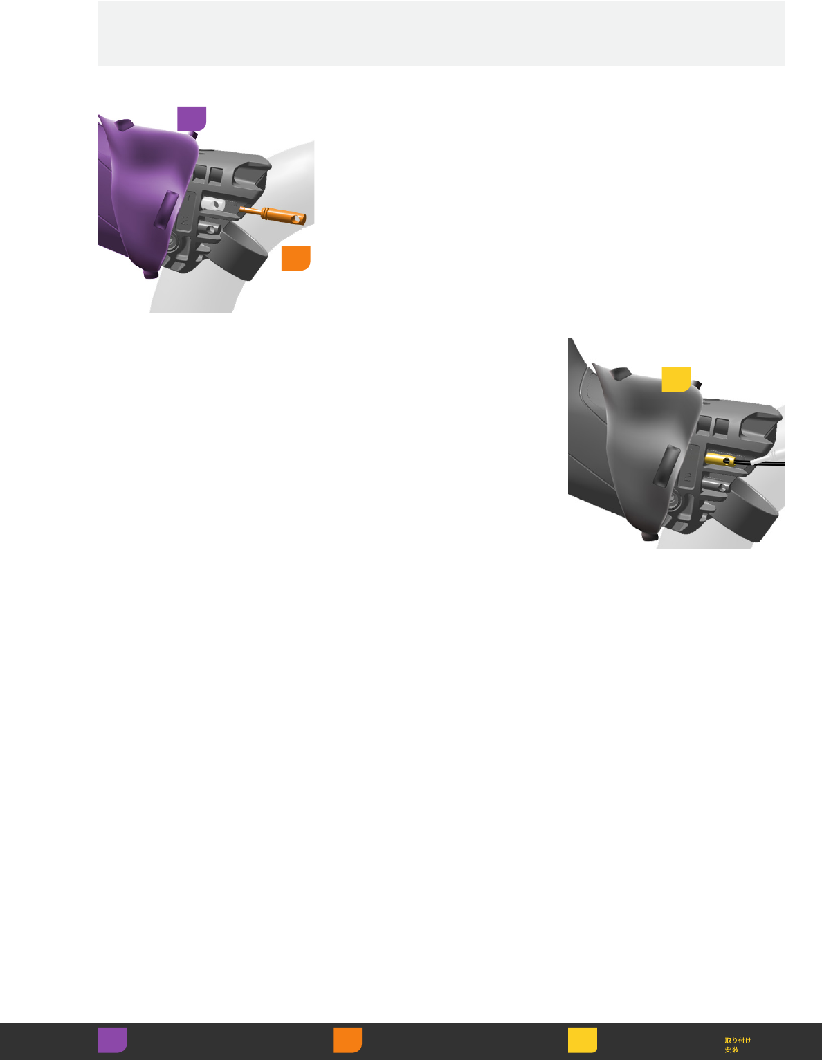
Remove the dummy plugs from
the BlipBox.
NOTICE
Do not discard the dummy plugs.
Reinstall if Blip connector wire
is removed.
WARNING
Do not use or clean the BlipBox or
eTap shifters without connector wires
or dummy plugs installed. Moisture will
damage the BlipBox and eTap shifters.
Remove the dummy plugs from
the BlipBox.
NOTICE
Do not discard the dummy plugs.
Reinstall if Blip connector wire
is removed.
WARNING
Do not use or clean the BlipBox or
eTap shifters without connector wires
or dummy plugs installed. Moisture will
damage the BlipBox and eTap shifters.
Remove the dummy plugs from
the BlipBox.
NOTICE
Do not discard the dummy plugs.
Reinstall if Blip connector wire
is removed.
WARNING
Do not use or clean the BlipBox or
eTap shifters without connector wires
or dummy plugs installed. Moisture will
damage the BlipBox and eTap shifters.
Remove the dummy plugs from
the BlipBox.
NOTICE
Do not discard the dummy plugs.
Reinstall if Blip connector wire
is removed.
WARNING
Do not use or clean the BlipBox or
eTap shifters without connector wires
or dummy plugs installed. Moisture will
damage the BlipBox and eTap shifters.
Remove the dummy plugs from
the BlipBox.
NOTICE
Do not discard the dummy plugs.
Reinstall if Blip connector wire
is removed.
WARNING
Do not use or clean the BlipBox or
eTap shifters without connector wires
or dummy plugs installed. Moisture will
damage the BlipBox and eTap shifters.
Remove the dummy plugs from
the BlipBox.
NOTICE
Do not discard the dummy plugs.
Reinstall if Blip connector wire
is removed.
WARNING
Do not use or clean the BlipBox or
eTap shifters without connector wires
or dummy plugs installed. Moisture will
damage the BlipBox and eTap shifters.
Remove the dummy plugs from
the BlipBox.
NOTICE
Do not discard the dummy plugs.
Reinstall if Blip connector wire
is removed.
WARNING
Do not use or clean the BlipBox or
eTap shifters without connector wires
or dummy plugs installed. Moisture will
damage the BlipBox and eTap shifters.
Remove the dummy plugs from
the BlipBox.
NOTICE
Do not discard the dummy plugs.
Reinstall if Blip connector wire
is removed.
WARNING
Do not use or clean the BlipBox or
eTap shifters without connector wires
or dummy plugs installed. Moisture will
damage the BlipBox and eTap shifters.
Remove the dummy plugs from
the BlipBox.
NOTICE
Do not discard the dummy plugs.
Reinstall if Blip connector wire
is removed.
WARNING
Do not use or clean the BlipBox or
eTap shifters without connector wires
or dummy plugs installed. Moisture will
damage the BlipBox and eTap shifters.
Remove Retirer Retirar
Entfernen Rimuovere 取り外し
Quitar Verwijderen 拆卸
1
9
BlipBox Mounts BlipBox Mounts BlipBox Mounts
BlipBox Mounts BlipBox Mounts BlipBox Mounts
BlipBox Mounts BlipBox Mounts BlipBox Mounts
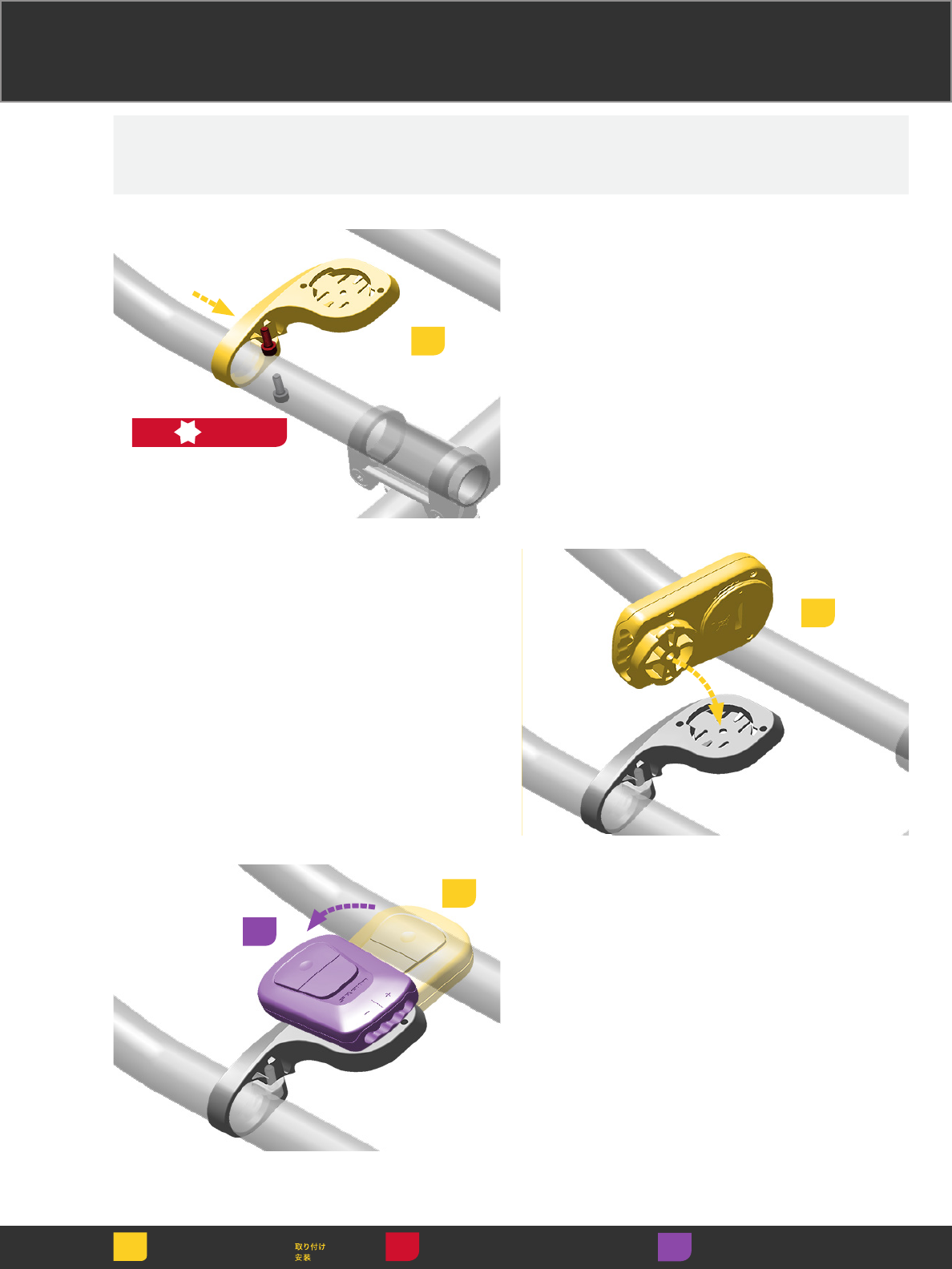
Install the mount
onto the aero bar
extension.
Install the mount
onto the aero bar
extension.
Install the mount
onto the aero bar
extension.
Install the mount
onto the aero bar
extension.
Install the mount
onto the aero bar
extension.
Install the mount
onto the aero bar
extension.
Install the mount
onto the aero bar
extension.
Install the mount
onto the aero bar
extension.
Install the mount
onto the aero bar
extension.
1
2
T25
1 N·m
(8.8 in-lb)
Install the BlipBox
onto the mount.
Install the BlipBox
onto the mount.
Install the BlipBox
onto the mount.
Install the BlipBox
onto the mount.
Install the BlipBox
onto the mount.
Install the BlipBox
onto the mount.
Install the BlipBox
onto the mount.
Install the BlipBox
onto the mount.
Install the BlipBox
onto the mount.
3
Twist the BlipBox
one quarter turn
to lock into place.
Twist the BlipBox
one quarter turn
to lock into place.
Twist the BlipBox
one quarter turn
to lock into place.
Twist the BlipBox
one quarter turn
to lock into place.
Twist the BlipBox
one quarter turn
to lock into place.
Twist the BlipBox
one quarter turn
to lock into place.
Twist the BlipBox
one quarter turn
to lock into place.
Twist the BlipBox
one quarter turn
to lock into place.
Twist the BlipBox
one quarter turn
to lock into place.
4
5
Install
Einbauen
Instalación
Installer
Installare
Monteren
Instalar Adjust Régler Ajustar
Einstellen Regolare 調節
Ajustar Afstellen 调节
Torque Serrage
Momento de torção
Drehmoment Coppia 締め付け
Par de apriete
Aandraaimoment
扭紧
Bar Extension Mount Bar Extension Mount Bar Extension Mount
Bar Extension Mount Bar Extension Mount Bar Extension Mount
Bar Extension Mount Bar Extension Mount Bar Extension Mount
10
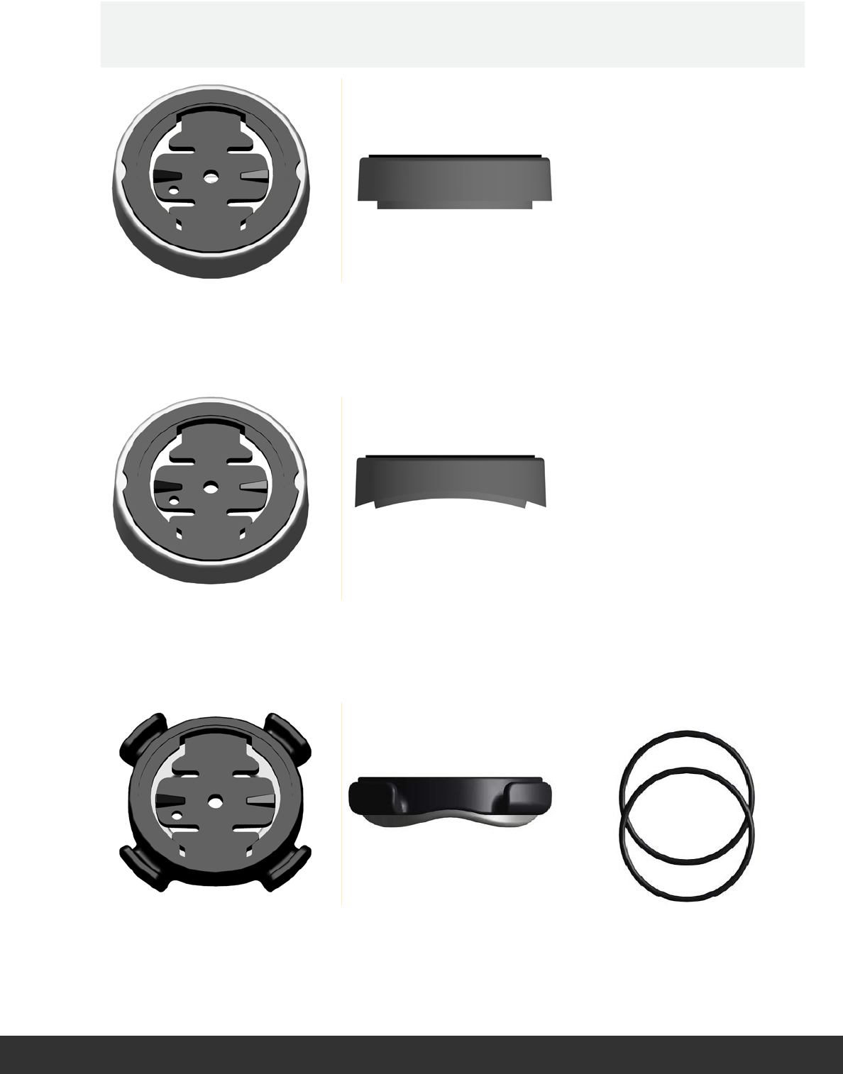
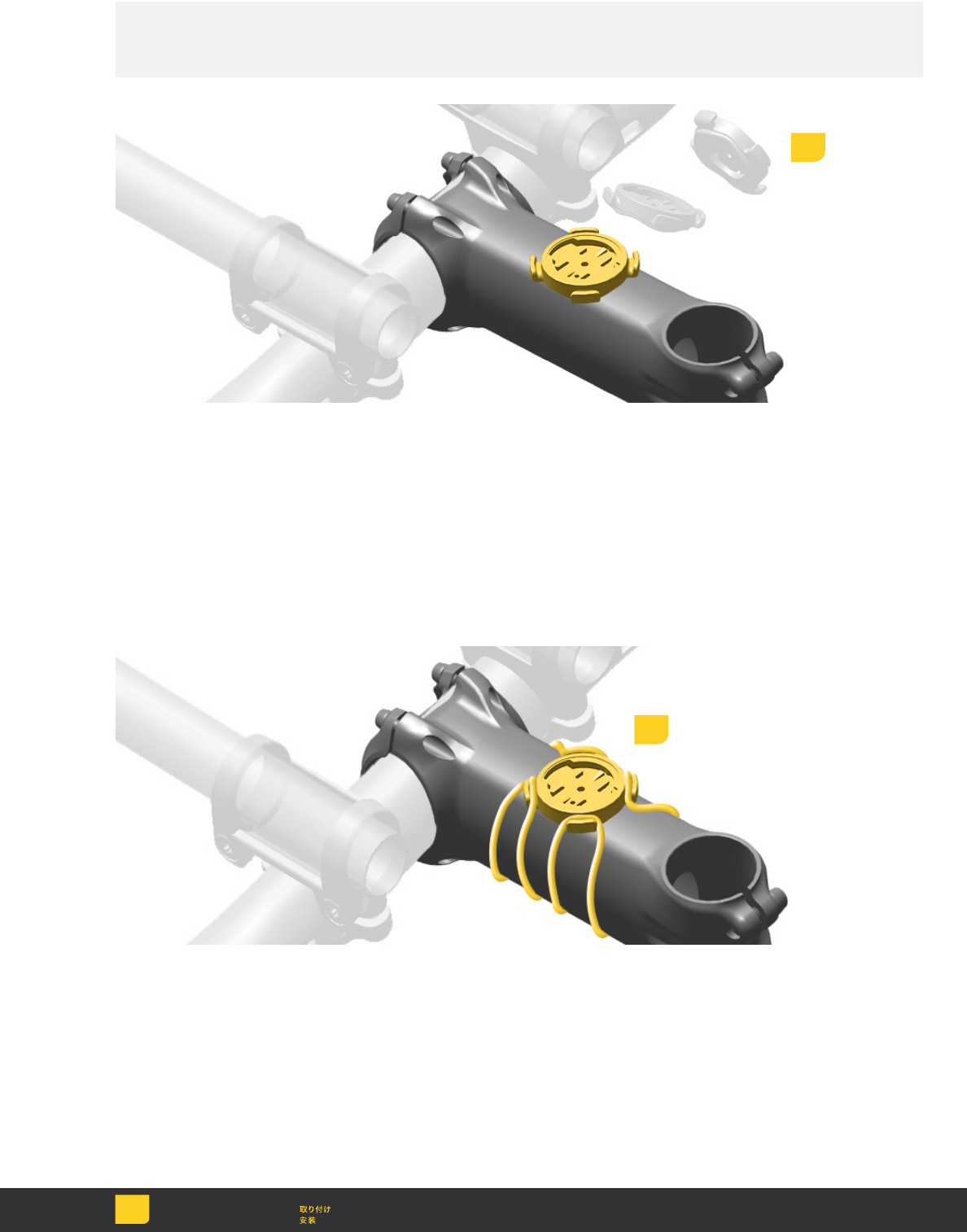
Stem Mounts Stem Mounts Stem Mounts
Stem Mounts Stem Mounts Stem Mounts
Stem Mounts Stem Mounts Stem Mounts
Flat Mount Flat Mount Flat Mount
Flat Mount Flat Mount Flat Mount
Flat Mount Flat Mount Flat Mount
Curved Mount Curved Mount Curved Mount
Curved Mount Curved Mount Curved Mount
Curved Mount Curved Mount Curved Mount
Rubber Band Mount Rubber Band Mount Rubber Band Mount
Rubber Band Mount Rubber Band Mount Rubber Band Mount
Rubber Band Mount Rubber Band Mount Rubber Band Mount
11
Install
Einbauen
Instalación
Installer
Installare
Monteren
Instalar
Adhesive Adhesive Adhesive
Adhesive Adhesive Adhesive
Adhesive Adhesive Adhesive
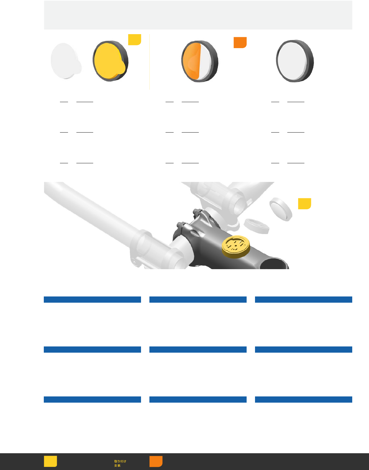
Attach the adhesive tab to the back
of the flat or curved puck mount and
remove the paper backing.
Attach the adhesive tab to the back
of the flat or curved puck mount and
remove the paper backing.
Attach the adhesive tab to the back
of the flat or curved puck mount and
remove the paper backing.
Attach the adhesive tab to the back
of the flat or curved puck mount and
remove the paper backing.
Attach the adhesive tab to the back
of the flat or curved puck mount and
remove the paper backing.
Attach the adhesive tab to the back
of the flat or curved puck mount and
remove the paper backing.
Attach the adhesive tab to the back
of the flat or curved puck mount and
remove the paper backing.
Attach the adhesive tab to the back
of the flat or curved puck mount and
remove the paper backing.
Attach the adhesive tab to the back
of the flat or curved puck mount and
remove the paper backing.
Position the mount in the desired
location and press down to attach.
NOTICE
Clean the stem surface with isopropyl
alcohol before attaching the mount.
Position the mount in the desired
location and press down to attach.
NOTICE
Clean the stem surface with isopropyl
alcohol before attaching the mount.
Position the mount in the desired
location and press down to attach.
NOTICE
Clean the stem surface with isopropyl
alcohol before attaching the mount.
Position the mount in the desired
location and press down to attach.
NOTICE
Clean the stem surface with isopropyl
alcohol before attaching the mount.
Position the mount in the desired
location and press down to attach.
NOTICE
Clean the stem surface with isopropyl
alcohol before attaching the mount.
Position the mount in the desired
location and press down to attach.
NOTICE
Clean the stem surface with isopropyl
alcohol before attaching the mount.
Position the mount in the desired
location and press down to attach.
NOTICE
Clean the stem surface with isopropyl
alcohol before attaching the mount.
Position the mount in the desired
location and press down to attach.
NOTICE
Clean the stem surface with isopropyl
alcohol before attaching the mount.
Position the mount in the desired
location and press down to attach.
NOTICE
Clean the stem surface with isopropyl
alcohol before attaching the mount.
Remove Retirer Retirar
Entfernen Rimuovere 取り外し
Quitar Verwijderen 拆卸
12
3
12
Install
Einbauen
Instalación
Installer
Installare
Monteren
Instalar
Rubber Band Rubber Band Rubber Band
Rubber Band Rubber Band Rubber Band
Rubber Band Rubber Band Rubber Band
Position the mount onto the stem in
the desired location.
Position the mount onto the stem in
the desired location.
Position the mount onto the stem in
the desired location.
Position the mount onto the stem in
the desired location.
Position the mount onto the stem in
the desired location.
Position the mount onto the stem in
the desired location.
Position the mount onto the stem in
the desired location.
Position the mount onto the stem in
the desired location.
Position the mount onto the stem in
the desired location.
Attach the mount to the stem with the
included rubber bands.
Attach the mount to the stem with the
included rubber bands.
Attach the mount to the stem with the
included rubber bands.
Attach the mount to the stem with the
included rubber bands.
Attach the mount to the stem with the
included rubber bands.
Attach the mount to the stem with the
included rubber bands.
Attach the mount to the stem with the
included rubber bands.
Attach the mount to the stem with the
included rubber bands.
Attach the mount to the stem with the
included rubber bands.
1
2
13
Install
Einbauen
Instalación
Installer
Installare
Monteren
Instalar
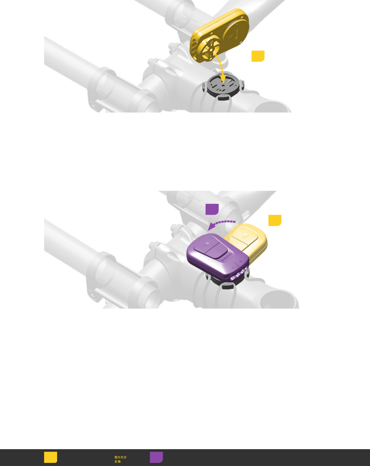
Install the BlipBox onto the mount. Install the BlipBox onto the mount. Install the BlipBox onto the mount.
Install the BlipBox onto the mount. Install the BlipBox onto the mount. Install the BlipBox onto the mount.
Install the BlipBox onto the mount. Install the BlipBox onto the mount. Install the BlipBox onto the mount.
Twist the BlipBox one quarter turn to
lock into place.
Twist the BlipBox one quarter turn to
lock into place.
Twist the BlipBox one quarter turn to
lock into place.
Twist the BlipBox one quarter turn to
lock into place.
Twist the BlipBox one quarter turn to
lock into place.
Twist the BlipBox one quarter turn to
lock into place.
Twist the BlipBox one quarter turn to
lock into place.
Twist the BlipBox one quarter turn to
lock into place.
Twist the BlipBox one quarter turn to
lock into place.
1
2
3
Adjust Régler Ajustar
Einstellen Regolare 調節
Ajustar Afstellen 调节
14
Blips Blips Blips
Blips Blips Blips
Blips Blips Blips
Each Blip satellite shifter actuates a
derailleur shift, inboard or outboard,
when the button is pressed. Each
Blip connects via connector wire to
either the BlipBox or an eTap™ road
shifter which is wirelessly paired to
each derailleur. The BlipBox or eTap™
shifter transmit the shift signal to each
derailleur to execute the gear shift.

15
Installation Installation Installation
Installation Installation Installation
Installation Installation Installation
NOTICE
Measure the length of wire required
and select the appropriate Blip wire
length before installing the Blip.
To avoid damage to wires, avoid
sharp bends.
Secure wires to the handlebar with
electrical tape.
Secure any loose wires together.
Wrap bar tape over the wires.
It is ok to wrap bar tape over Blips.
16
Install
Einbauen
Instalación
Installer
Installare
Monteren
Instalar
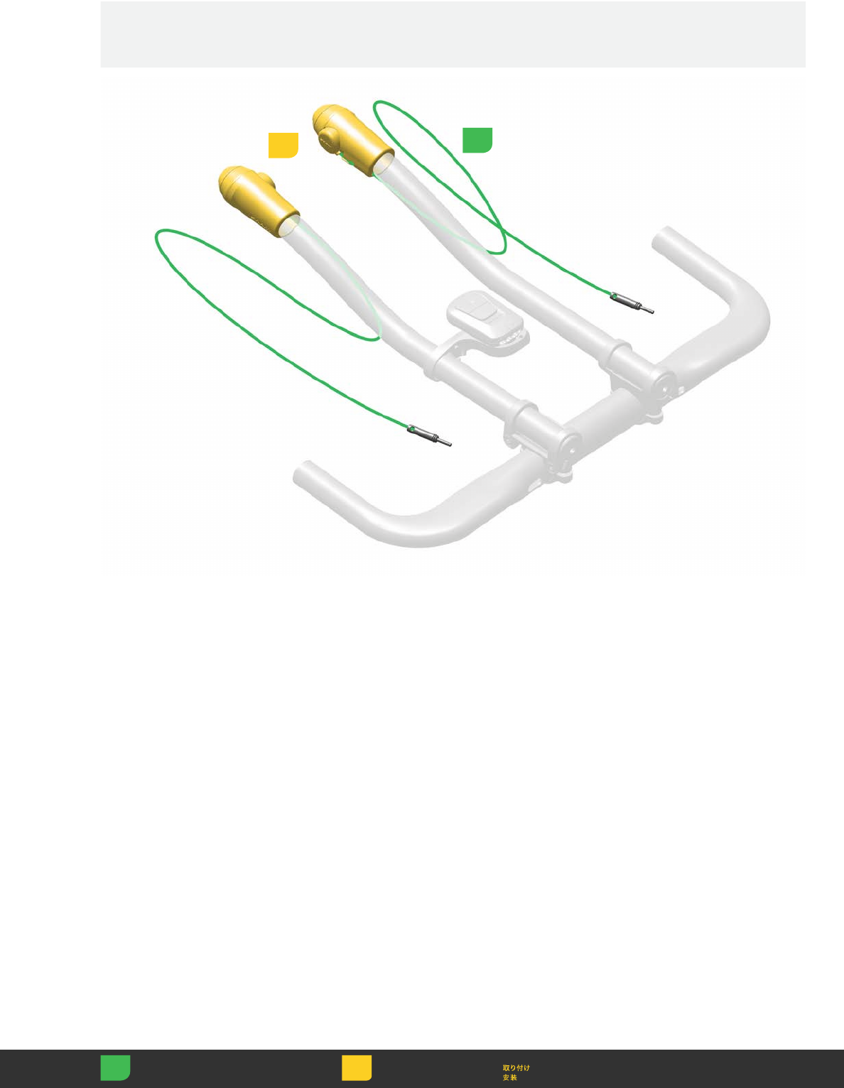
Bar Extension Bar Extension Bar Extension
Bar Extension Bar Extension Bar Extension
Bar Extension Bar Extension Bar Extension
Clean the bar extension with
isopropyl alcohol.
Attach the Blip to the bar with the
adhesive tab in the desired
ergonomic position.
NOTICE
The Blip can be located anywhere on
the bar extension.
Clean the bar extension with
isopropyl alcohol.
Attach the Blip to the bar with the
adhesive tab in the desired
ergonomic position.
NOTICE
The Blip can be located anywhere on
the bar extension.
Clean the bar extension with
isopropyl alcohol.
Attach the Blip to the bar with the
adhesive tab in the desired
ergonomic position.
NOTICE
The Blip can be located anywhere on
the bar extension.
Clean the bar extension with
isopropyl alcohol.
Attach the Blip to the bar with the
adhesive tab in the desired
ergonomic position.
NOTICE
The Blip can be located anywhere on
the bar extension.
Clean the bar extension with
isopropyl alcohol.
Attach the Blip to the bar with the
adhesive tab in the desired
ergonomic position.
NOTICE
The Blip can be located anywhere on
the bar extension.
Clean the bar extension with
isopropyl alcohol.
Attach the Blip to the bar with the
adhesive tab in the desired
ergonomic position.
NOTICE
The Blip can be located anywhere on
the bar extension.
Clean the bar extension with
isopropyl alcohol.
Attach the Blip to the bar with the
adhesive tab in the desired
ergonomic position.
NOTICE
The Blip can be located anywhere on
the bar extension.
Clean the bar extension with
isopropyl alcohol.
Attach the Blip to the bar with the
adhesive tab in the desired
ergonomic position.
NOTICE
The Blip can be located anywhere on
the bar extension.
Clean the bar extension with
isopropyl alcohol.
Attach the Blip to the bar with the
adhesive tab in the desired
ergonomic position.
NOTICE
The Blip can be located anywhere on
the bar extension.
2
Measure Mesurer Medir
Messen Misurare 計測
Medir Meten 测量
1
17
Install
Einbauen
Instalación
Installer
Installare
Monteren
Instalar
Blip Grip Blip Grip Blip Grip
Blip Grip Blip Grip Blip Grip
Blip Grip Blip Grip Blip Grip
Install each BlipGrip onto each
bar extension.
Install each BlipGrip onto each
bar extension.
Install each BlipGrip onto each
bar extension.
Install each BlipGrip onto each
bar extension.
Install each BlipGrip onto each
bar extension.
Install each BlipGrip onto each
bar extension.
Install each BlipGrip onto each
bar extension.
Install each BlipGrip onto each
bar extension.
Install each BlipGrip onto each
bar extension.
2
Measure Mesurer Medir
Messen Misurare 計測
Medir Meten 测量
1
18
Torque Serrage
Momento de torção
Drehmoment Coppia 締め付け
Par de apriete
Aandraaimoment
扭紧
3
2
0.23 N·m
(2.0 in-lb)
2
Rotate and adjust each BlipGrip to the
desired ergonomic position.
Rotate and adjust each BlipGrip to the
desired ergonomic position.
Rotate and adjust each BlipGrip to the
desired ergonomic position.
Rotate and adjust each BlipGrip to the
desired ergonomic position.
Rotate and adjust each BlipGrip to the
desired ergonomic position.
Rotate and adjust each BlipGrip to the
desired ergonomic position.
Rotate and adjust each BlipGrip to the
desired ergonomic position.
Rotate and adjust each BlipGrip to the
desired ergonomic position.
Rotate and adjust each BlipGrip to the
desired ergonomic position.
Tighten each clamp bolt. Tighten each clamp bolt. Tighten each clamp bolt.
Tighten each clamp bolt. Tighten each clamp bolt. Tighten each clamp bolt.
Tighten each clamp bolt. Tighten each clamp bolt. Tighten each clamp bolt.
Adjust Régler Ajustar
Einstellen Regolare 調節
Ajustar Afstellen 调节
19
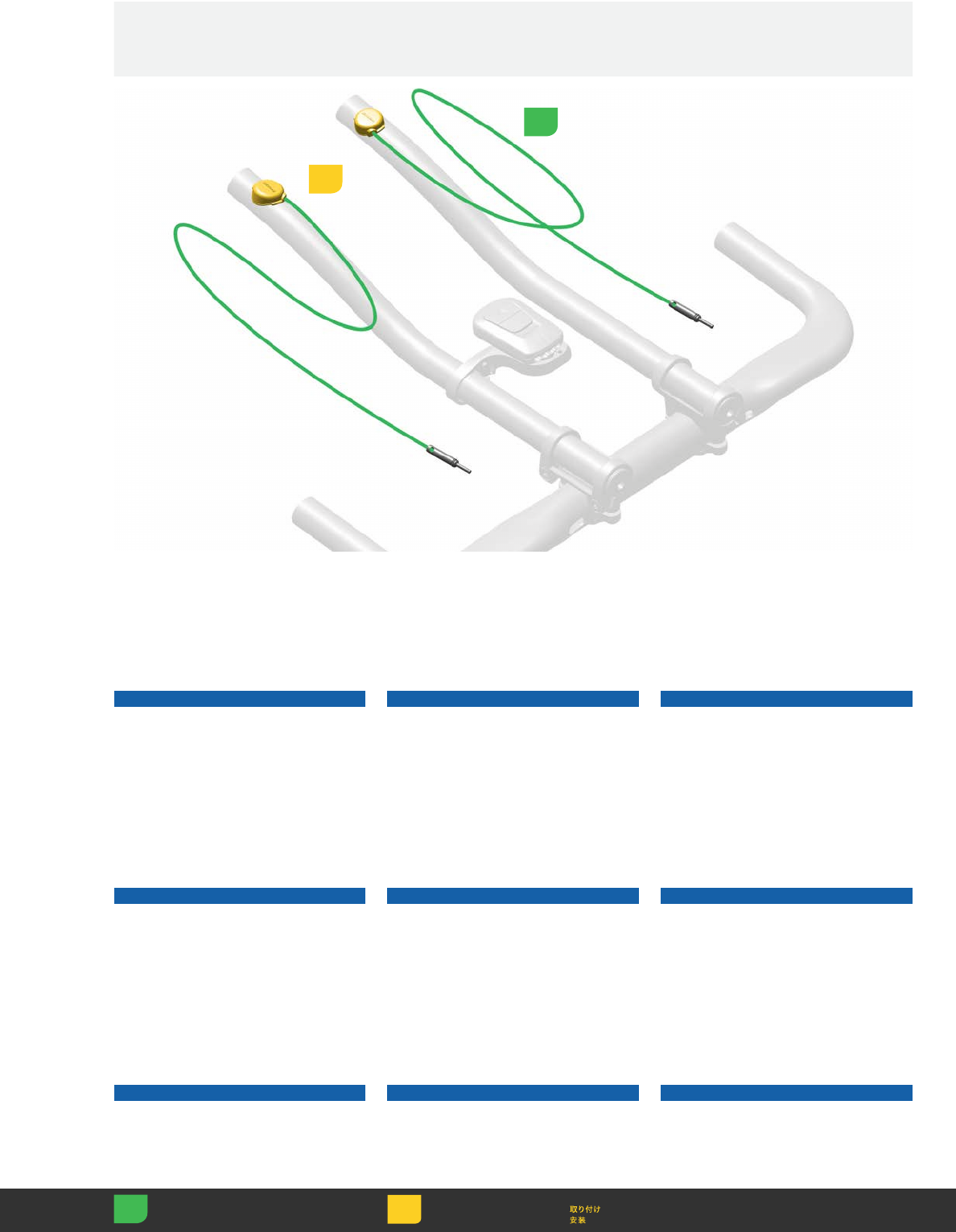
NOTICE
At least one Blip wire must have a
minimum of 100 mm of uninterupted
exposed wire for proper signal
transmission. Routing wires under
bar tape does not hinder signal
transmission and is acceptable. Before
use, test for proper function.
NOTICE
At least one Blip wire must have a
minimum of 100 mm of uninterupted
exposed wire for proper signal
transmission. Routing wires under
bar tape does not hinder signal
transmission and is acceptable. Before
use, test for proper function.
NOTICE
At least one Blip wire must have a
minimum of 100 mm of uninterupted
exposed wire for proper signal
transmission. Routing wires under
bar tape does not hinder signal
transmission and is acceptable. Before
use, test for proper function.
NOTICE
At least one Blip wire must have a
minimum of 100 mm of uninterupted
exposed wire for proper signal
transmission. Routing wires under
bar tape does not hinder signal
transmission and is acceptable. Before
use, test for proper function.
NOTICE
At least one Blip wire must have a
minimum of 100 mm of uninterupted
exposed wire for proper signal
transmission. Routing wires under
bar tape does not hinder signal
transmission and is acceptable. Before
use, test for proper function.
NOTICE
At least one Blip wire must have a
minimum of 100 mm of uninterupted
exposed wire for proper signal
transmission. Routing wires under
bar tape does not hinder signal
transmission and is acceptable. Before
use, test for proper function.
NOTICE
At least one Blip wire must have a
minimum of 100 mm of uninterupted
exposed wire for proper signal
transmission. Routing wires under
bar tape does not hinder signal
transmission and is acceptable. Before
use, test for proper function.
NOTICE
At least one Blip wire must have a
minimum of 100 mm of uninterupted
exposed wire for proper signal
transmission. Routing wires under
bar tape does not hinder signal
transmission and is acceptable. Before
use, test for proper function.
NOTICE
At least one Blip wire must have a
minimum of 100 mm of uninterupted
exposed wire for proper signal
transmission. Routing wires under
bar tape does not hinder signal
transmission and is acceptable. Before
use, test for proper function.
Blip Wire Blip Wire Blip Wire
Blip Wire Blip Wire Blip Wire
Blip Wire Blip Wire Blip Wire
100 mm
Measure Mesurer Medir
Messen Misurare 計測
Medir Meten 测量
20
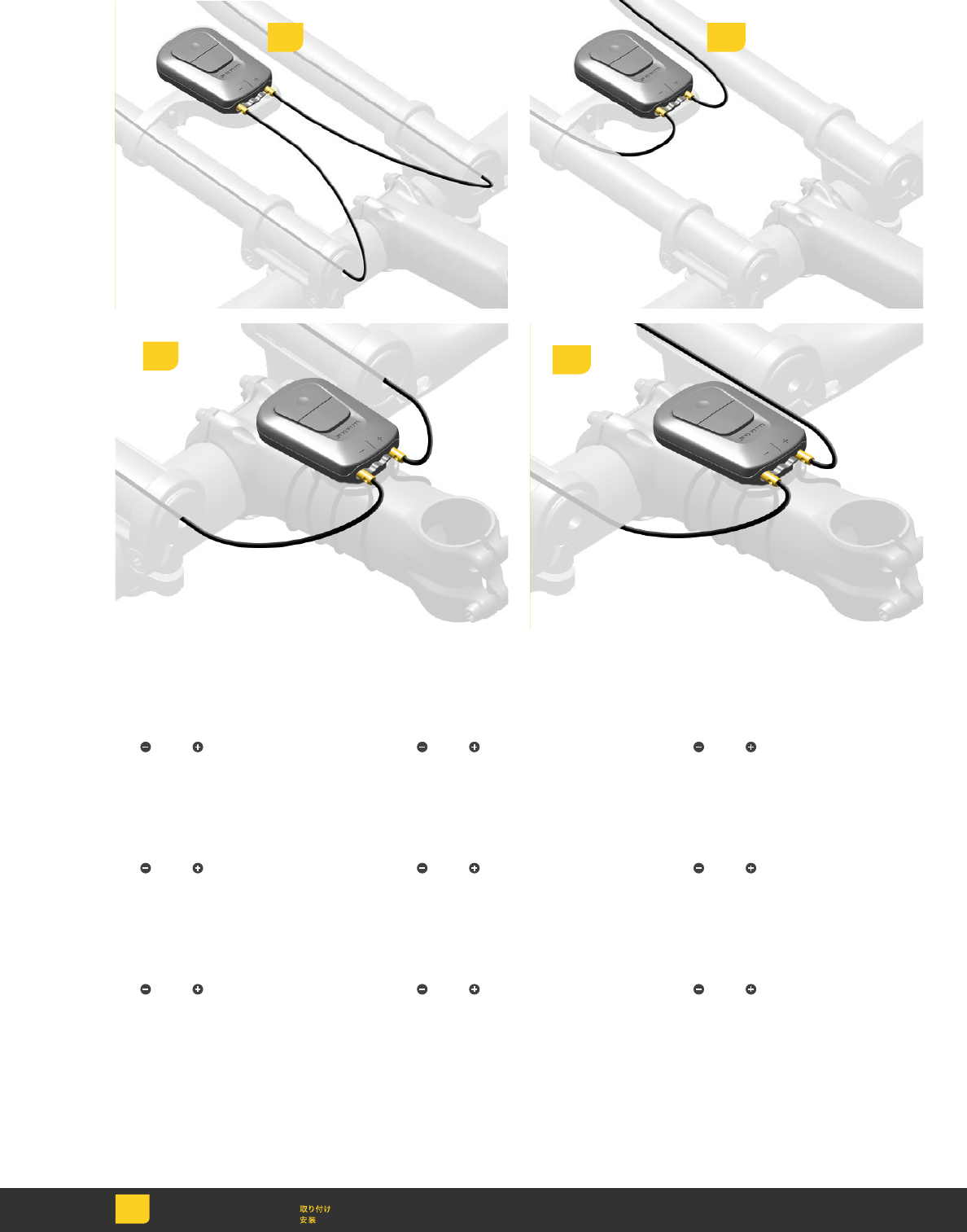
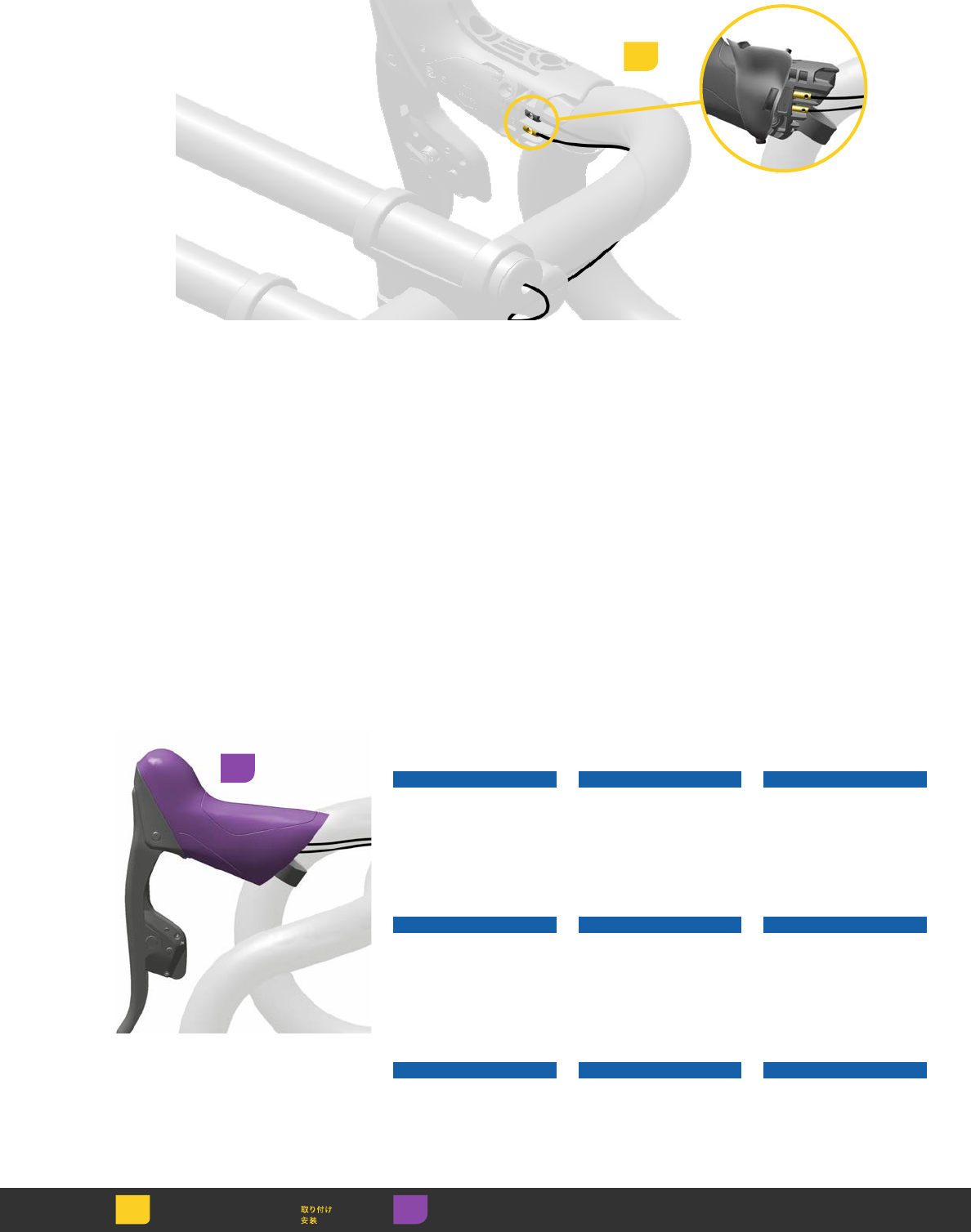
Route each Blip wire from the end of
the bar extension, internally (1a) or
externally (1b), to the BlipBox. Plug
each connector into the BlipBox;
left , right .
Route each Blip wire from the end of
the bar extension, internally (1a) or
externally (1b), to the BlipBox. Plug
each connector into the BlipBox;
left , right .
Route each Blip wire from the end of
the bar extension, internally (1a) or
externally (1b), to the BlipBox. Plug
each connector into the BlipBox;
left , right .
Route each Blip wire from the end of
the bar extension, internally (1a) or
externally (1b), to the BlipBox. Plug
each connector into the BlipBox;
left , right .
Route each Blip wire from the end of
the bar extension, internally (1a) or
externally (1b), to the BlipBox. Plug
each connector into the BlipBox;
left , right .
Route each Blip wire from the end of
the bar extension, internally (1a) or
externally (1b), to the BlipBox. Plug
each connector into the BlipBox;
left , right .
Route each Blip wire from the end of
the bar extension, internally (1a) or
externally (1b), to the BlipBox. Plug
each connector into the BlipBox;
left , right .
Route each Blip wire from the end of
the bar extension, internally (1a) or
externally (1b), to the BlipBox. Plug
each connector into the BlipBox;
left , right .
Route each Blip wire from the end of
the bar extension, internally (1a) or
externally (1b), to the BlipBox. Plug
each connector into the BlipBox;
left , right .
1a 1b
Install
Einbauen
Instalación
Installer
Installare
Monteren
Instalar
1a 1b
21
1
2
Clean the handlebar with isopropyl
alcohol.
Attach the Blip to the handlebar
with the adhesive tab in the desired
ergonomic position.
Clean the handlebar with isopropyl
alcohol.
Attach the Blip to the handlebar
with the adhesive tab in the desired
ergonomic position.
Clean the handlebar with isopropyl
alcohol.
Attach the Blip to the handlebar
with the adhesive tab in the desired
ergonomic position.
Clean the handlebar with isopropyl
alcohol.
Attach the Blip to the handlebar
with the adhesive tab in the desired
ergonomic position.
Clean the handlebar with isopropyl
alcohol.
Attach the Blip to the handlebar
with the adhesive tab in the desired
ergonomic position.
Clean the handlebar with isopropyl
alcohol.
Attach the Blip to the handlebar
with the adhesive tab in the desired
ergonomic position.
Clean the handlebar with isopropyl
alcohol.
Attach the Blip to the handlebar
with the adhesive tab in the desired
ergonomic position.
Clean the handlebar with isopropyl
alcohol.
Attach the Blip to the handlebar
with the adhesive tab in the desired
ergonomic position.
Clean the handlebar with isopropyl
alcohol.
Attach the Blip to the handlebar
with the adhesive tab in the desired
ergonomic position.
Aero Bar Aero Bar Aero Bar
Aero Bar Aero Bar Aero Bar
Aero Bar Aero Bar Aero Bar
Install
Einbauen
Instalación
Installer
Installare
Monteren
Instalar
Measure Mesurer Medir
Messen Misurare 計測
Medir Meten 测量
1
22
1a
1b
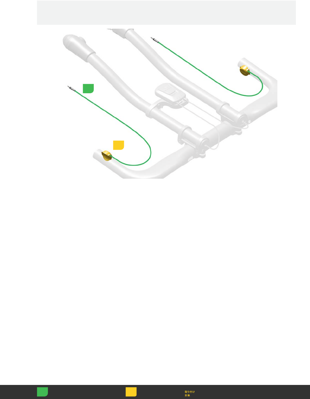
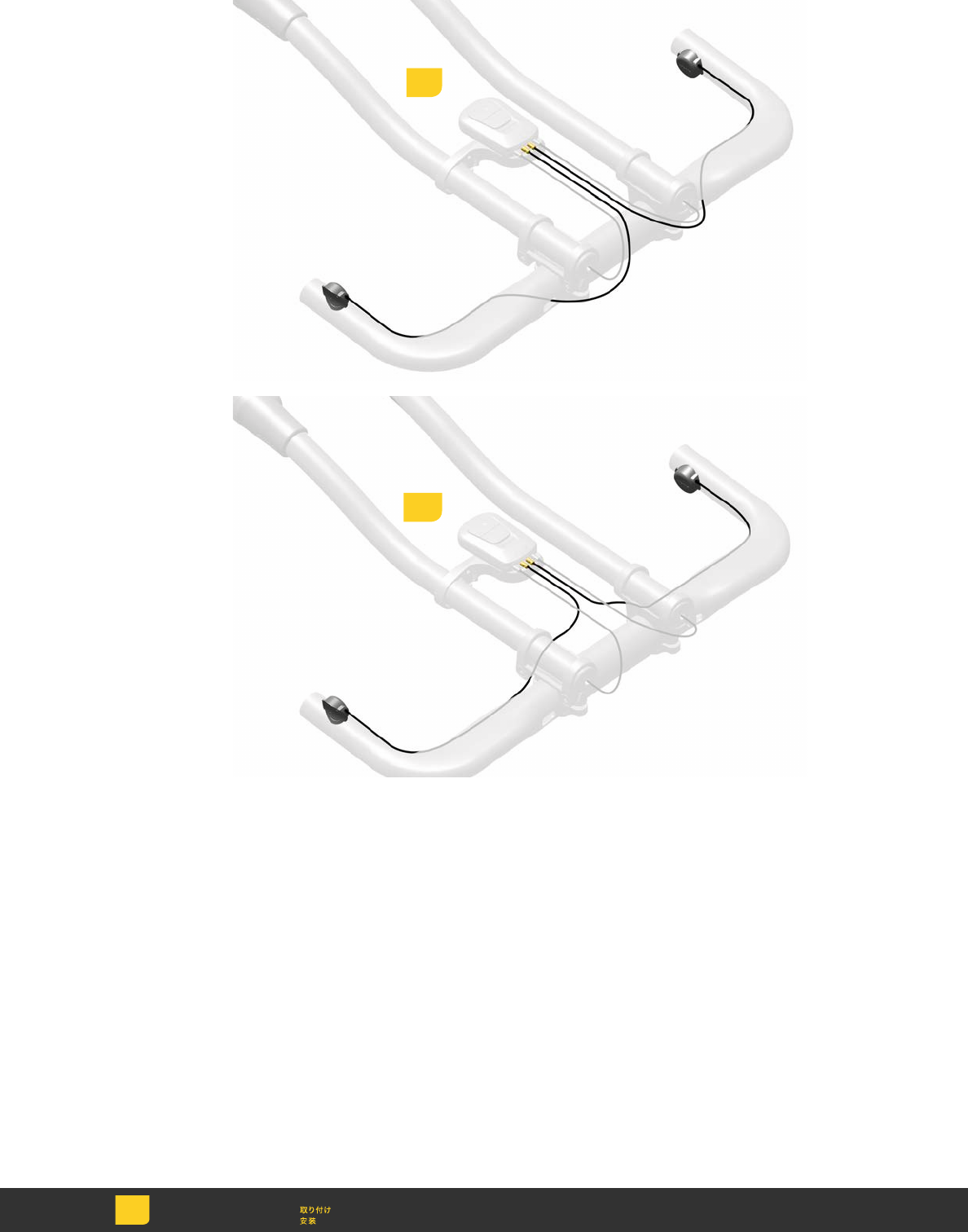
Route each Blip wire, internally (1a) or
externally (1b), on the handlebar and
plug the connector into the BlipBox;
left (-), right (+).
Route each Blip wire, internally (1a) or
externally (1b), on the handlebar and
plug the connector into the BlipBox;
left (-), right (+).
Route each Blip wire, internally (1a) or
externally (1b), on the handlebar and
plug the connector into the BlipBox;
left (-), right (+).
Route each Blip wire, internally (1a) or
externally (1b), on the handlebar and
plug the connector into the BlipBox;
left (-), right (+).
Route each Blip wire, internally (1a) or
externally (1b), on the handlebar and
plug the connector into the BlipBox;
left (-), right (+).
Route each Blip wire, internally (1a) or
externally (1b), on the handlebar and
plug the connector into the BlipBox;
left (-), right (+).
Route each Blip wire, internally (1a) or
externally (1b), on the handlebar and
plug the connector into the BlipBox;
left (-), right (+).
Route each Blip wire, internally (1a) or
externally (1b), on the handlebar and
plug the connector into the BlipBox;
left (-), right (+).
Route each Blip wire, internally (1a) or
externally (1b), on the handlebar and
plug the connector into the BlipBox;
left (-), right (+).
Install
Einbauen
Instalación
Installer
Installare
Monteren
Instalar
23
Drop Bar Drop Bar Drop Bar
Drop Bar Drop Bar Drop Bar
Drop Bar Drop Bar Drop Bar
Install
Einbauen
Instalación
Installer
Installare
Monteren
Instalar
Measure Mesurer Medir
Messen Misurare 計測
Medir Meten 测量
2
Clean the handlebar surface with
isopropyl alcohol.
Attach the Blip to the handlebar
with the adhesive tab in the desired
ergonomic position.
Clean the handlebar surface with
isopropyl alcohol.
Attach the Blip to the handlebar
with the adhesive tab in the desired
ergonomic position.
Clean the handlebar surface with
isopropyl alcohol.
Attach the Blip to the handlebar
with the adhesive tab in the desired
ergonomic position.
Clean the handlebar surface with
isopropyl alcohol.
Attach the Blip to the handlebar
with the adhesive tab in the desired
ergonomic position.
Clean the handlebar surface with
isopropyl alcohol.
Attach the Blip to the handlebar
with the adhesive tab in the desired
ergonomic position.
Clean the handlebar surface with
isopropyl alcohol.
Attach the Blip to the handlebar
with the adhesive tab in the desired
ergonomic position.
Clean the handlebar surface with
isopropyl alcohol.
Attach the Blip to the handlebar
with the adhesive tab in the desired
ergonomic position.
Clean the handlebar surface with
isopropyl alcohol.
Attach the Blip to the handlebar
with the adhesive tab in the desired
ergonomic position.
Clean the handlebar surface with
isopropyl alcohol.
Attach the Blip to the handlebar
with the adhesive tab in the desired
ergonomic position.
1
Option 1 Option 1 Option 1
Option 1 Option 1 Option 1
Option 1 Option 1 Option 1
24
Install
Einbauen
Instalación
Installer
Installare
Monteren
Instalar Torque Serrage
Momento de torção
Drehmoment Coppia 締め付け
Par de apriete
Aandraaimoment
扭紧
Measure Mesurer Medir
Messen Misurare 計測
Medir Meten 测量
2
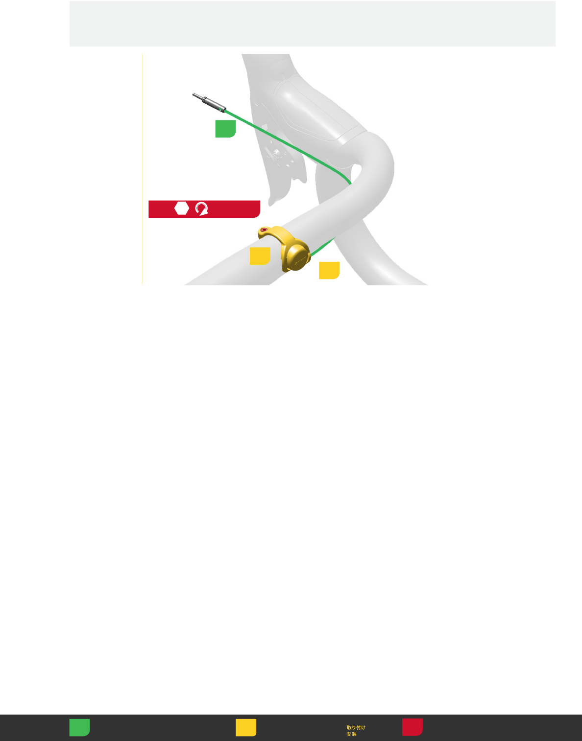
Insert the Blip into the clamp. Attach
the clamp to the handlebar and rotate
to the desired position. Tighten the
clamp bolt.
Insert the Blip into the clamp. Attach
the clamp to the handlebar and rotate
to the desired position. Tighten the
clamp bolt.
Insert the Blip into the clamp. Attach
the clamp to the handlebar and rotate
to the desired position. Tighten the
clamp bolt.
Insert the Blip into the clamp. Attach
the clamp to the handlebar and rotate
to the desired position. Tighten the
clamp bolt.
Insert the Blip into the clamp. Attach
the clamp to the handlebar and rotate
to the desired position. Tighten the
clamp bolt.
Insert the Blip into the clamp. Attach
the clamp to the handlebar and rotate
to the desired position. Tighten the
clamp bolt.
Insert the Blip into the clamp. Attach
the clamp to the handlebar and rotate
to the desired position. Tighten the
clamp bolt.
Insert the Blip into the clamp. Attach
the clamp to the handlebar and rotate
to the desired position. Tighten the
clamp bolt.
Insert the Blip into the clamp. Attach
the clamp to the handlebar and rotate
to the desired position. Tighten the
clamp bolt.
3
4
2.5
0.23 N·m
(2.0 in-lb)
1
Option 2 Option 2 Option 2
Option 2 Option 2 Option 2
Option 2 Option 2 Option 2
25
Install
Einbauen
Instalación
Installer
Installare
Monteren
Instalar
Remove Retirer Retirar
Entfernen Rimuovere 取り外し
Quitar Verwijderen 拆卸
Adjust Régler Ajustar
Einstellen Regolare 調節
Ajustar Afstellen 调节
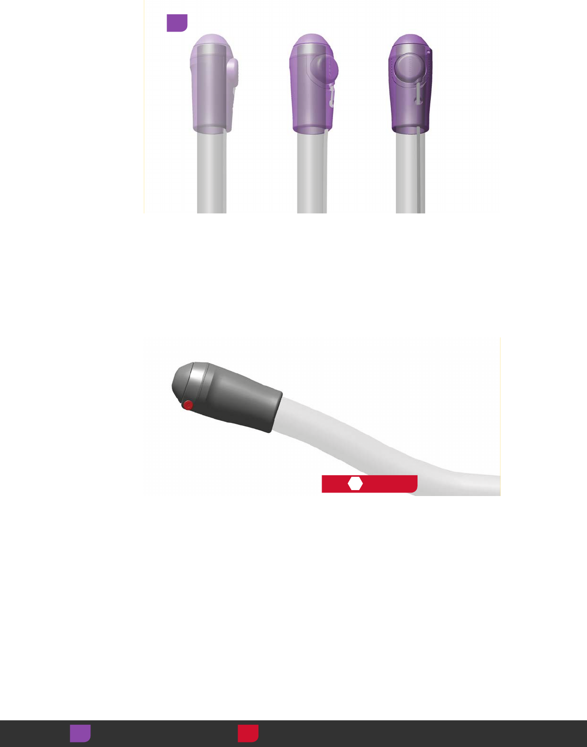
3
Fold the hood cover
back and remove the
dummy plug.
Fold the hood cover
back and remove the
dummy plug.
Fold the hood cover
back and remove the
dummy plug.
Fold the hood cover
back and remove the
dummy plug.
Fold the hood cover
back and remove the
dummy plug.
Fold the hood cover
back and remove the
dummy plug.
Fold the hood cover
back and remove the
dummy plug.
Fold the hood cover
back and remove the
dummy plug.
Fold the hood cover
back and remove the
dummy plug.
1
2
Shifter Shifter Shifter
Shifter Shifter Shifter
Shifter Shifter Shifter
Plug the wire connector
into the shifter.
Plug the wire connector
into the shifter.
Plug the wire connector
into the shifter.
Plug the wire connector
into the shifter.
Plug the wire connector
into the shifter.
Plug the wire connector
into the shifter.
Plug the wire connector
into the shifter.
Plug the wire connector
into the shifter.
Plug the wire connector
into the shifter.
26
Install
Einbauen
Instalación
Installer
Installare
Monteren
Instalar
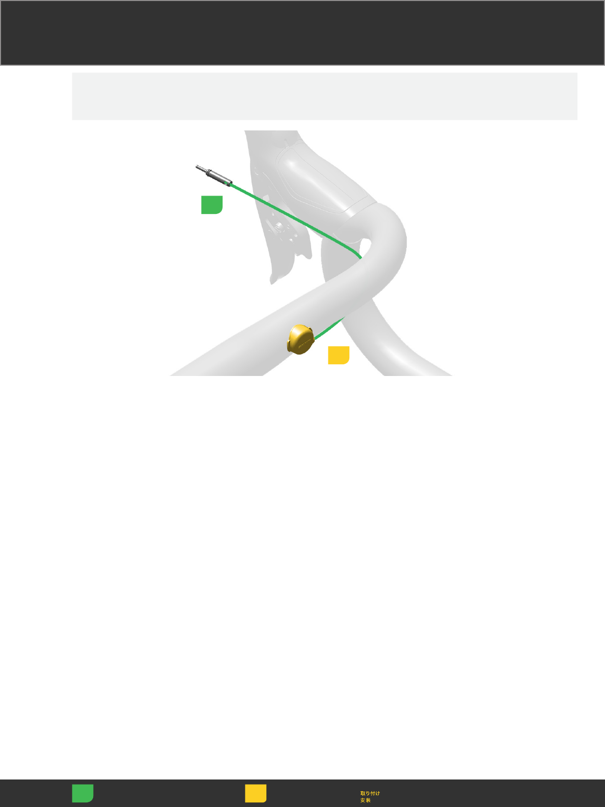
Refer to pages 16-18 for bar extension
Blip installation.
Route the Blip wire from the bar
extension under the drop handlebar
and plug it into the eTap shifter input 2.
Refer to pages 16-18 for bar extension
Blip installation.
Route the Blip wire from the bar
extension under the drop handlebar
and plug it into the shifter input 2.
Refer to pages 16-18 for bar extension
Blip installation.
Route the Blip wire from the bar
extension under the drop handlebar
and plug it into the shifter input 2.
Refer to pages 16-18 for bar extension
Blip installation.
Route the Blip wire from the bar
extension under the drop handlebar
and plug it into the shifter input 2.
Refer to pages 16-18 for bar extension
Blip installation.
Route the Blip wire from the bar
extension under the drop handlebar
and plug it into the shifter input 2.
Refer to pages 16-18 for bar extension
Blip installation.
Route the Blip wire from the bar
extension under the drop handlebar
and plug it into the shifter input 2.
Refer to pages 16-18 for bar extension
Blip installation.
Route the Blip wire from the bar
extension under the drop handlebar
and plug it into the shifter input 2.
Refer to pages 16-18 for bar extension
Blip installation.
Route the Blip wire from the bar
extension under the drop handlebar
and plug it into the shifter input 2.
Refer to pages 16-18 for bar extension
Blip installation.
Route the Blip wire from the bar
extension under the drop handlebar
and plug it into the shifter input 2.
1
Adjust Régler Ajustar
Einstellen Regolare 調節
Ajustar Afstellen 调节
2
Fold the hood back onto
the shifter.
NOTICE
Handlebar tape can be
wrapped over the Blip
button and wire.
Fold the hood back onto
the shifter.
NOTICE
Handlebar tape can be
wrapped over the Blip
button and wire.
Fold the hood back onto
the shifter.
NOTICE
Handlebar tape can be
wrapped over the Blip
button and wire.
Fold the hood back onto
the shifter.
NOTICE
Handlebar tape can be
wrapped over the Blip
button and wire.
Fold the hood back onto
the shifter.
NOTICE
Handlebar tape can be
wrapped over the Blip
button and wire.
Fold the hood back onto
the shifter.
NOTICE
Handlebar tape can be
wrapped over the Blip
button and wire.
Fold the hood back onto
the shifter.
NOTICE
Handlebar tape can be
wrapped over the Blip
button and wire.
Fold the hood back onto
the shifter.
NOTICE
Handlebar tape can be
wrapped over the Blip
button and wire.
Fold the hood back onto
the shifter.
NOTICE
Handlebar tape can be
wrapped over the Blip
button and wire.
27
Pairing Pairing Pairing
Pairing Pairing Pairing
Pairing Pairing Pairing
Adjust Régler Ajustar
Einstellen Regolare 調節
Ajustar Afstellen 调节
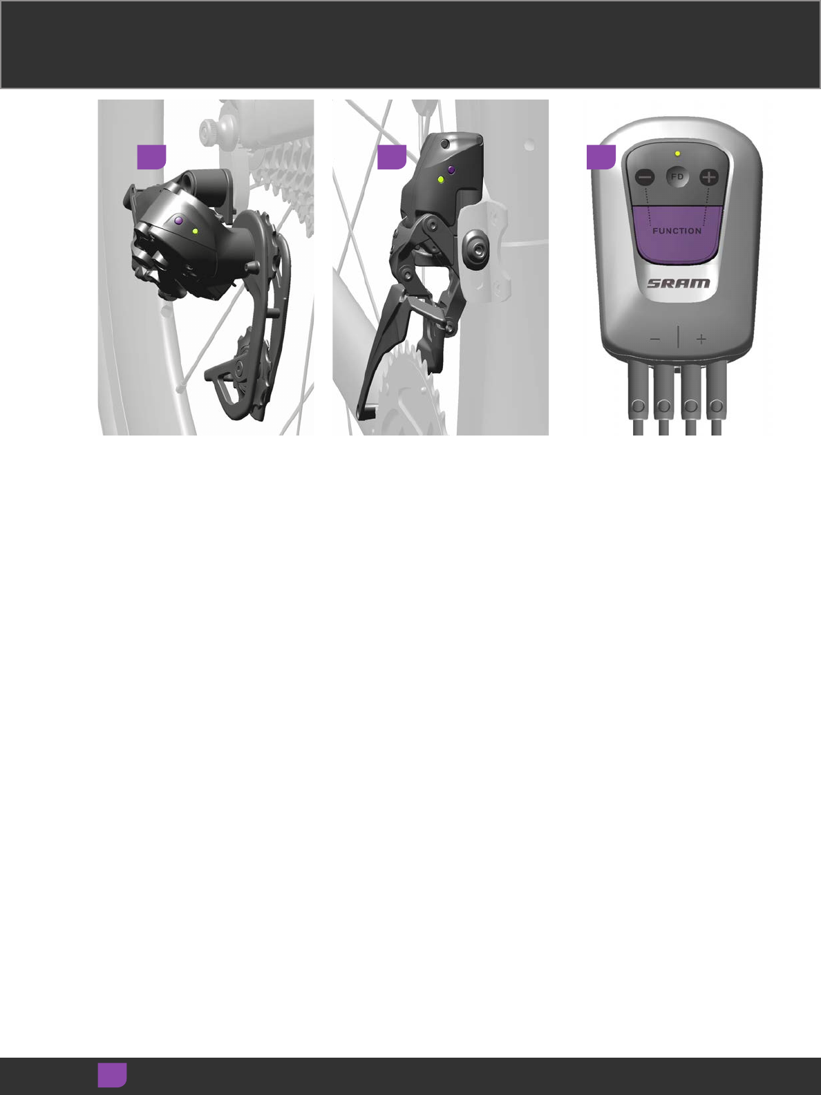
Begin the pairing session at the rear
derailleur. Press and hold the function
button on the rear derailleur until the
green LED blinks slowly, then release.
Begin the pairing session at the rear
derailleur. Press and hold the function
button on the rear derailleur until the
green LED blinks slowly, then release.
Begin the pairing session at the rear
derailleur. Press and hold the function
button on the rear derailleur until the
green LED blinks slowly, then release.
Begin the pairing session at the rear
derailleur. Press and hold the function
button on the rear derailleur until the
green LED blinks slowly, then release.
Begin the pairing session at the rear
derailleur. Press and hold the function
button on the rear derailleur until the
green LED blinks slowly, then release.
Begin the pairing session at the rear
derailleur. Press and hold the function
button on the rear derailleur until the
green LED blinks slowly, then release.
Begin the pairing session at the rear
derailleur. Press and hold the function
button on the rear derailleur until the
green LED blinks slowly, then release.
Begin the pairing session at the rear
derailleur. Press and hold the function
button on the rear derailleur until the
green LED blinks slowly, then release.
Begin the pairing session at the rear
derailleur. Press and hold the function
button on the rear derailleur until the
green LED blinks slowly, then release.
Individually pair the other components
in any order. Press and hold the
function button on each component
until its LED blinks quickly, then
release.
Individually pair the other components
in any order. Press and hold the
function button on each component
until its LED blinks quickly, then
release.
Individually pair the other components
in any order. Press and hold the
function button on each component
until its LED blinks quickly, then
release.
Individually pair the other components
in any order. Press and hold the
function button on each component
until its LED blinks quickly, then
release.
Individually pair the other components
in any order. Press and hold the
function button on each component
until its LED blinks quickly, then
release.
Individually pair the other components
in any order. Press and hold the
function button on each component
until its LED blinks quickly, then
release.
Individually pair the other components
in any order. Press and hold the
function button on each component
until its LED blinks quickly, then
release.
Individually pair the other components
in any order. Press and hold the
function button on each component
until its LED blinks quickly, then
release.
Individually pair the other components
in any order. Press and hold the
function button on each component
until its LED blinks quickly, then
release.
1 2 3
28
Adjust Régler Ajustar
Einstellen Regolare 調節
Ajustar Afstellen 调节
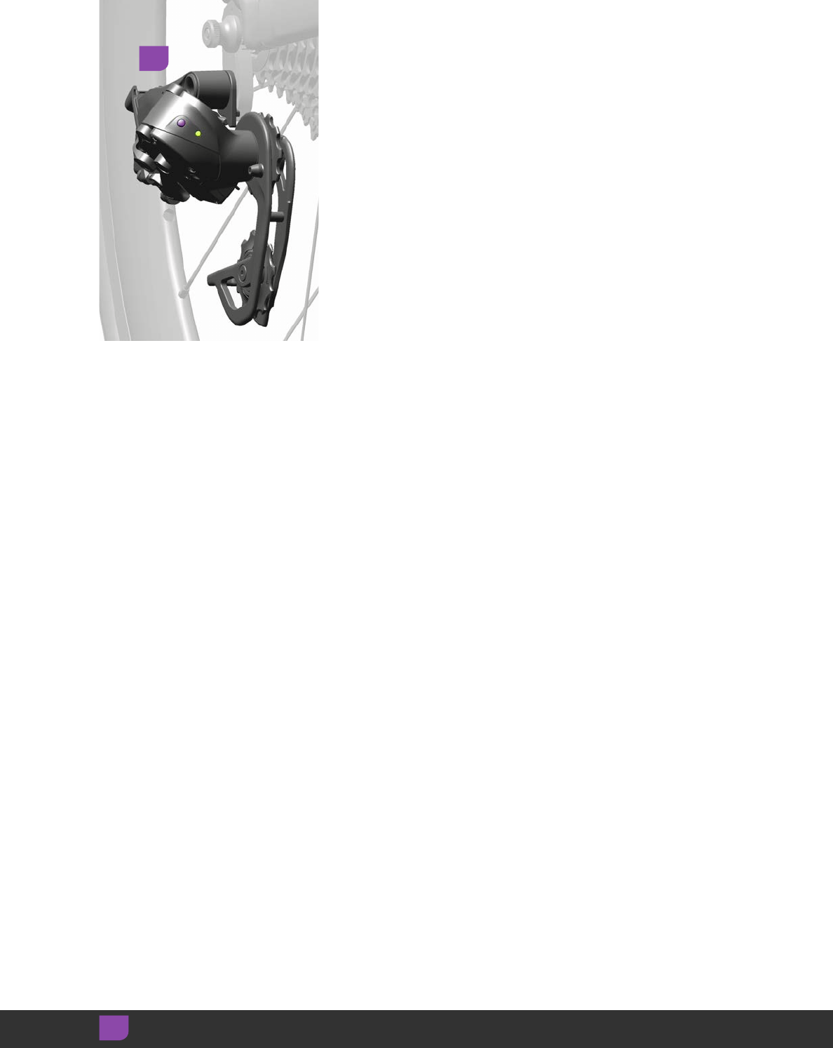
To end the pairing session, press and
release the function button on the rear
derailleur. Verify the system is paired
by shifting the derailleurs in both
directions.
To end the pairing session, press and
release the function button on the rear
derailleur. Verify the system is paired
by shifting the derailleurs in both
directions.
To end the pairing session, press and
release the function button on the rear
derailleur. Verify the system is paired
by shifting the derailleurs in both
directions.
To end the pairing session, press and
release the function button on the rear
derailleur. Verify the system is paired
by shifting the derailleurs in both
directions.
To end the pairing session, press and
release the function button on the rear
derailleur. Verify the system is paired
by shifting the derailleurs in both
directions.
To end the pairing session, press and
release the function button on the rear
derailleur. Verify the system is paired
by shifting the derailleurs in both
directions.
To end the pairing session, press and
release the function button on the rear
derailleur. Verify the system is paired
by shifting the derailleurs in both
directions.
To end the pairing session, press and
release the function button on the rear
derailleur. Verify the system is paired
by shifting the derailleurs in both
directions.
To end the pairing session, press and
release the function button on the rear
derailleur. Verify the system is paired
by shifting the derailleurs in both
directions.
4
29
Shifting Shifting Shifting
Shifting Shifting Shifting
Shifting Shifting Shifting
Rear Derailleur Rear Derailleur Rear Derailleur
Rear Derailleur Rear Derailleur Rear Derailleur
Rear Derailleur Rear Derailleur Rear Derailleur
Adjust Régler Ajustar
Einstellen Regolare 調節
Ajustar Afstellen 调节
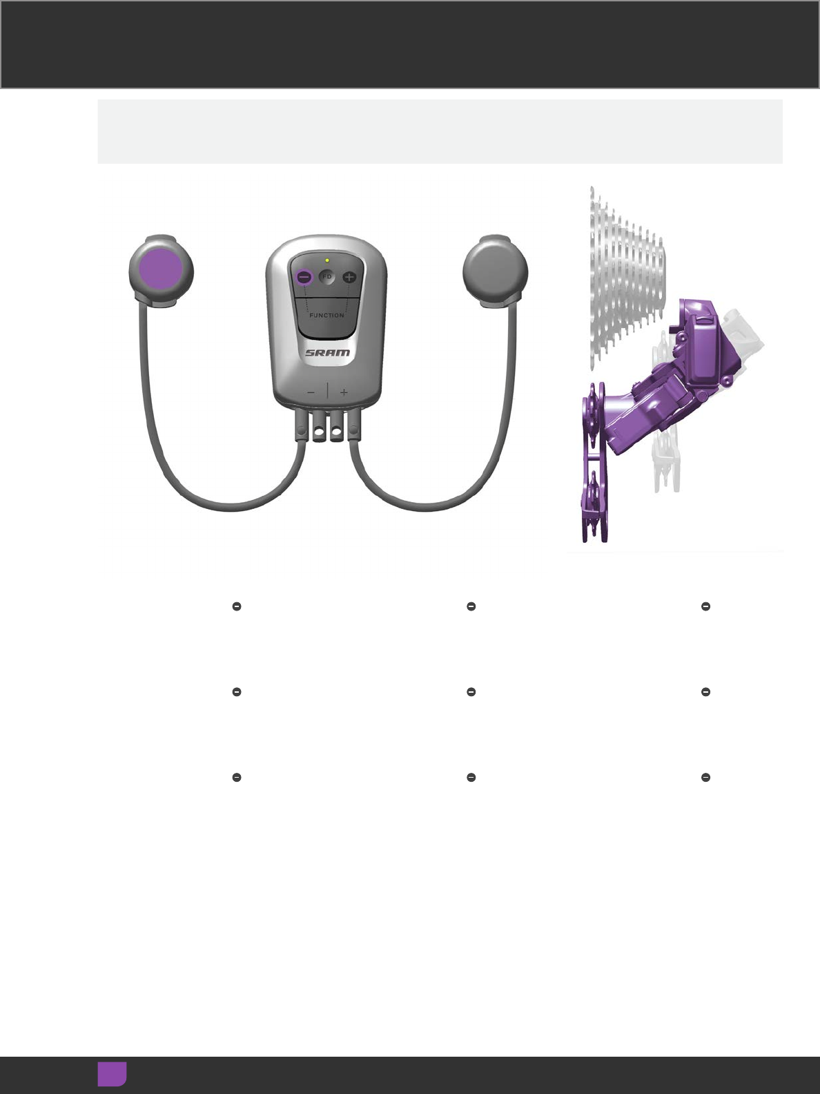
Press the left blip or the on the
BlipBox to move the rear derailleur
inboard. Press and hold for multiple
shifts.
Press the left blip or the on the
BlipBox to move the rear derailleur
inboard. Press and hold for multiple
shifts.
Press the left blip or the on the
BlipBox to move the rear derailleur
inboard. Press and hold for multiple
shifts.
Press the left blip or the on the
BlipBox to move the rear derailleur
inboard. Press and hold for multiple
shifts.
Press the left blip or the on the
BlipBox to move the rear derailleur
inboard. Press and hold for multiple
shifts.
Press the left blip or the on the
BlipBox to move the rear derailleur
inboard. Press and hold for multiple
shifts.
Press the left blip or the on the
BlipBox to move the rear derailleur
inboard. Press and hold for multiple
shifts.
Press the left blip or the on the
BlipBox to move the rear derailleur
inboard. Press and hold for multiple
shifts.
Press the left blip or the on the
BlipBox to move the rear derailleur
inboard. Press and hold for multiple
shifts.
30
Adjust Régler Ajustar
Einstellen Regolare 調節
Ajustar Afstellen 调节
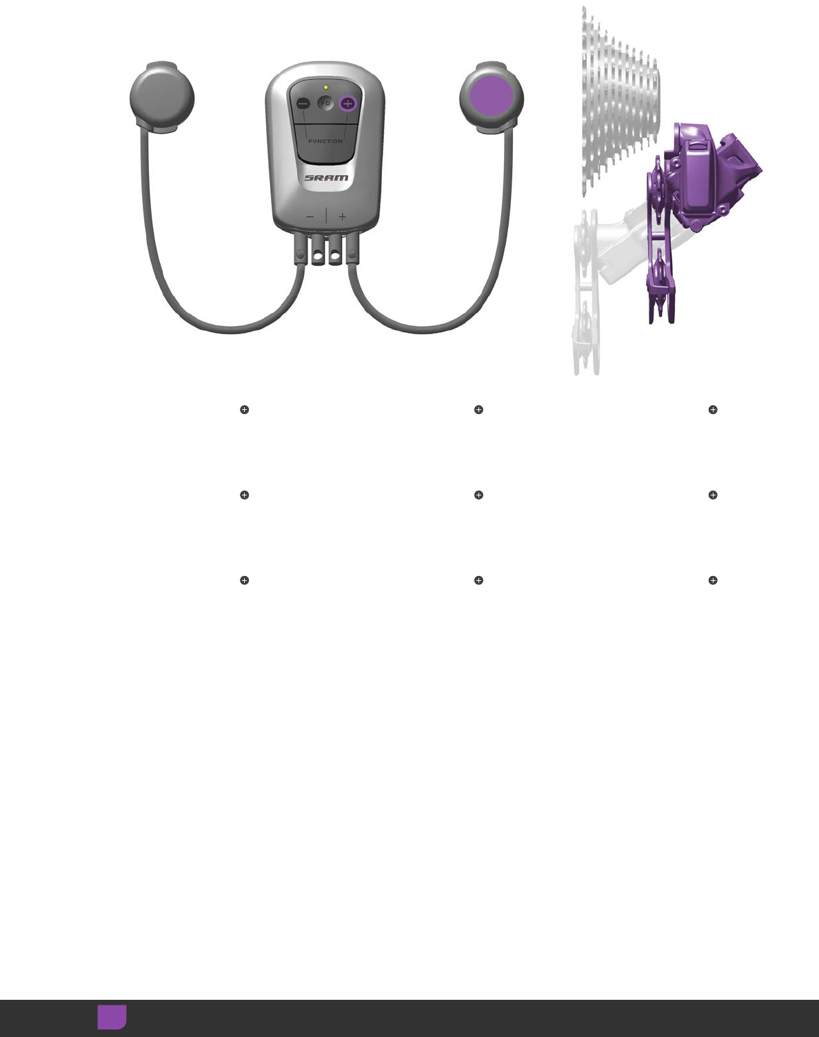
Press the right blip or the on the
BlipBox to move the rear derailleur
outboard. Press and hold for
multiple shifts.
Press the right blip or the on the
BlipBox to move the rear derailleur
outboard. Press and hold for
multiple shifts.
Press the right blip or the on the
BlipBox to move the rear derailleur
outboard. Press and hold for
multiple shifts.
Press the right blip or the on the
BlipBox to move the rear derailleur
outboard. Press and hold for
multiple shifts.
Press the right blip or the on the
BlipBox to move the rear derailleur
outboard. Press and hold for
multiple shifts.
Press the right blip or the on the
BlipBox to move the rear derailleur
outboard. Press and hold for
multiple shifts.
Press the right blip or the on the
BlipBox to move the rear derailleur
outboard. Press and hold for
multiple shifts.
Press the right blip or the on the
BlipBox to move the rear derailleur
outboard. Press and hold for
multiple shifts.
Press the right blip or the on the
BlipBox to move the rear derailleur
outboard. Press and hold for
multiple shifts.
31
Adjust Régler Ajustar
Einstellen Regolare 調節
Ajustar Afstellen 调节
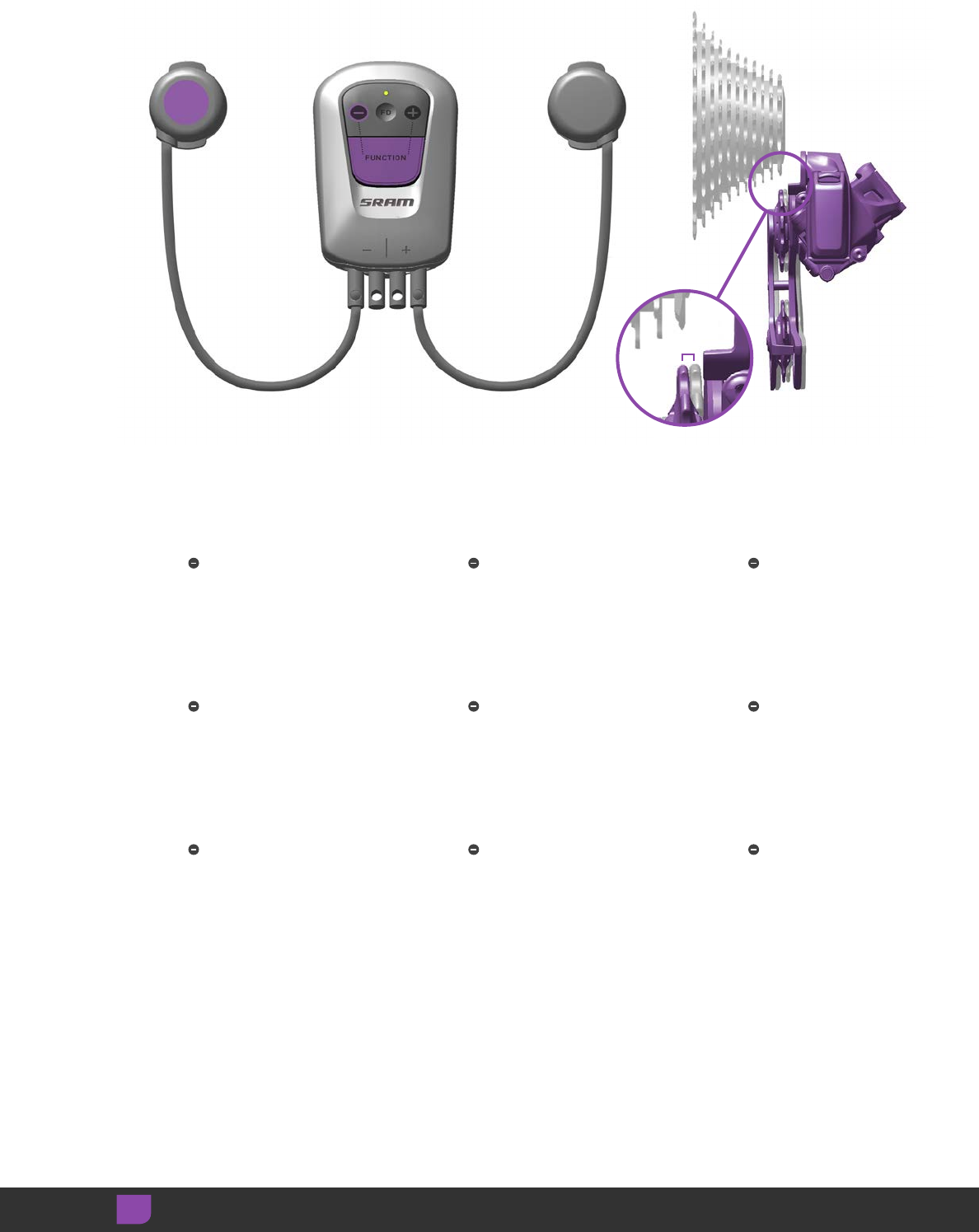
Rear derailleur micro adjustment can
eliminate unwanted chain rub or noise.
To micro adjust inboard, press and hold
the FUNCTION button, then press the
left blip or button. Repeat until the
adjustment is complete.
Rear derailleur micro adjustment can
eliminate unwanted chain rub or noise.
To micro adjust inboard, press and hold
the FUNCTION button, then press the
left blip or button. Repeat until the
adjustment is complete.
Rear derailleur micro adjustment can
eliminate unwanted chain rub or noise.
To micro adjust inboard, press and hold
the FUNCTION button, then press the
left blip or button. Repeat until the
adjustment is complete.
Rear derailleur micro adjustment can
eliminate unwanted chain rub or noise.
To micro adjust inboard, press and hold
the FUNCTION button, then press the
left blip or button. Repeat until the
adjustment is complete.
Rear derailleur micro adjustment can
eliminate unwanted chain rub or noise.
To micro adjust inboard, press and hold
the FUNCTION button, then press the
left blip or button. Repeat until the
adjustment is complete.
Rear derailleur micro adjustment can
eliminate unwanted chain rub or noise.
To micro adjust inboard, press and hold
the FUNCTION button, then press the
left blip or button. Repeat until the
adjustment is complete.
Rear derailleur micro adjustment can
eliminate unwanted chain rub or noise.
To micro adjust inboard, press and hold
the FUNCTION button, then press the
left blip or button. Repeat until the
adjustment is complete.
Rear derailleur micro adjustment can
eliminate unwanted chain rub or noise.
To micro adjust inboard, press and hold
the FUNCTION button, then press the
left blip or button. Repeat until the
adjustment is complete.
Rear derailleur micro adjustment can
eliminate unwanted chain rub or noise.
To micro adjust inboard, press and hold
the FUNCTION button, then press the
left blip or button. Repeat until the
adjustment is complete.
0.25mm
32
Adjust Régler Ajustar
Einstellen Regolare 調節
Ajustar Afstellen 调节
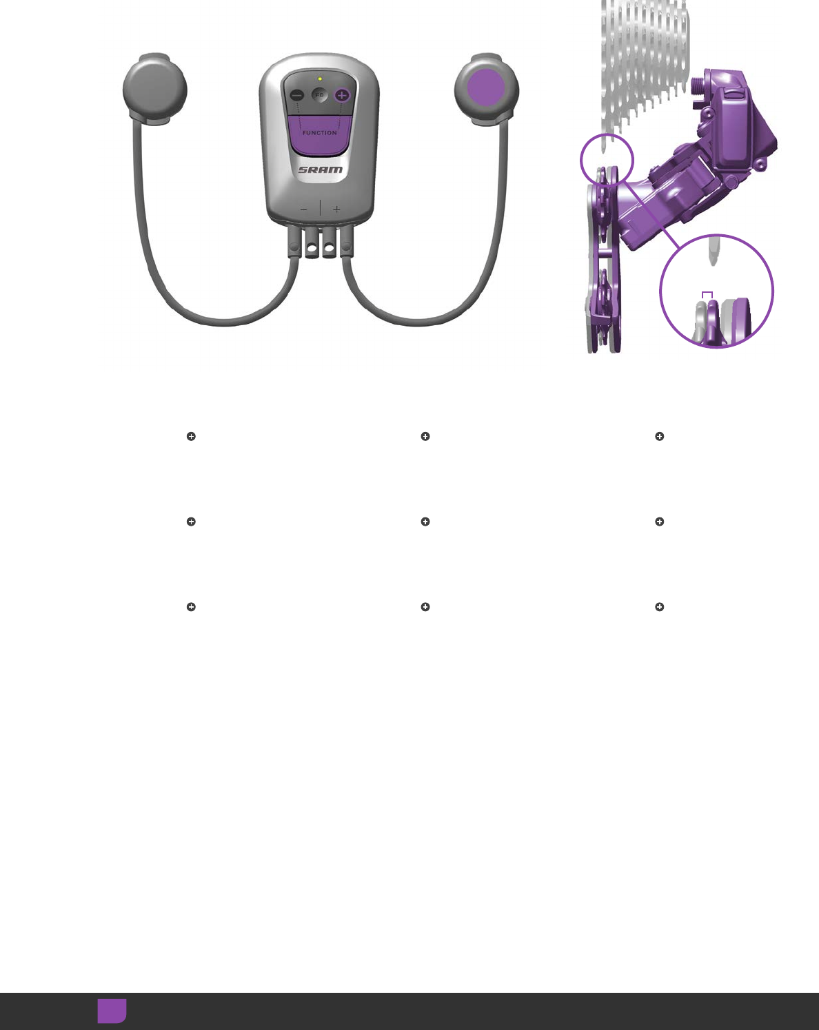
To micro adjust outboard, press and
hold the FUNCTION button, then press
the right blip or button. Repeat until
the adjustment is complete.
To micro adjust outboard, press and
hold the FUNCTION button, then press
the right blip or button. Repeat until
the adjustment is complete.
To micro adjust outboard, press and
hold the FUNCTION button, then press
the right blip or button. Repeat until
the adjustment is complete.
To micro adjust outboard, press and
hold the FUNCTION button, then press
the right blip or button. Repeat until
the adjustment is complete.
To micro adjust outboard, press and
hold the FUNCTION button, then press
the right blip or button. Repeat until
the adjustment is complete.
To micro adjust outboard, press and
hold the FUNCTION button, then press
the right blip or button. Repeat until
the adjustment is complete.
To micro adjust outboard, press and
hold the FUNCTION button, then press
the right blip or button. Repeat until
the adjustment is complete.
To micro adjust outboard, press and
hold the FUNCTION button, then press
the right blip or button. Repeat until
the adjustment is complete.
To micro adjust outboard, press and
hold the FUNCTION button, then press
the right blip or button. Repeat until
the adjustment is complete.
0.25mm
33
Front Derailleur Front Derailleur Front Derailleur
Front Derailleur Front Derailleur Front Derailleur
Front Derailleur Front Derailleur Front Derailleur
Adjust Régler Ajustar
Einstellen Regolare 調節
Ajustar Afstellen 调节
Press both Blips simultaneously, or
press FD on the Blip Box, to move the
front derailleur inboard or outboard.
Press both Blips simultaneously, or
press FD on the Blip Box, to move the
front derailleur inboard or outboard.
Press both Blips simultaneously, or
press FD on the Blip Box, to move the
front derailleur inboard or outboard.
Press both Blips simultaneously, or
press FD on the Blip Box, to move the
front derailleur inboard or outboard.
Press both Blips simultaneously, or
press FD on the Blip Box, to move the
front derailleur inboard or outboard.
Press both Blips simultaneously, or
press FD on the Blip Box, to move the
front derailleur inboard or outboard.
Press both Blips simultaneously, or
press FD on the Blip Box, to move the
front derailleur inboard or outboard.
Press both Blips simultaneously, or
press FD on the Blip Box, to move the
front derailleur inboard or outboard.
Press both Blips simultaneously, or
press FD on the Blip Box, to move the
front derailleur inboard or outboard.
34
Battery Battery Battery
Battery Battery Battery
Battery Battery Battery
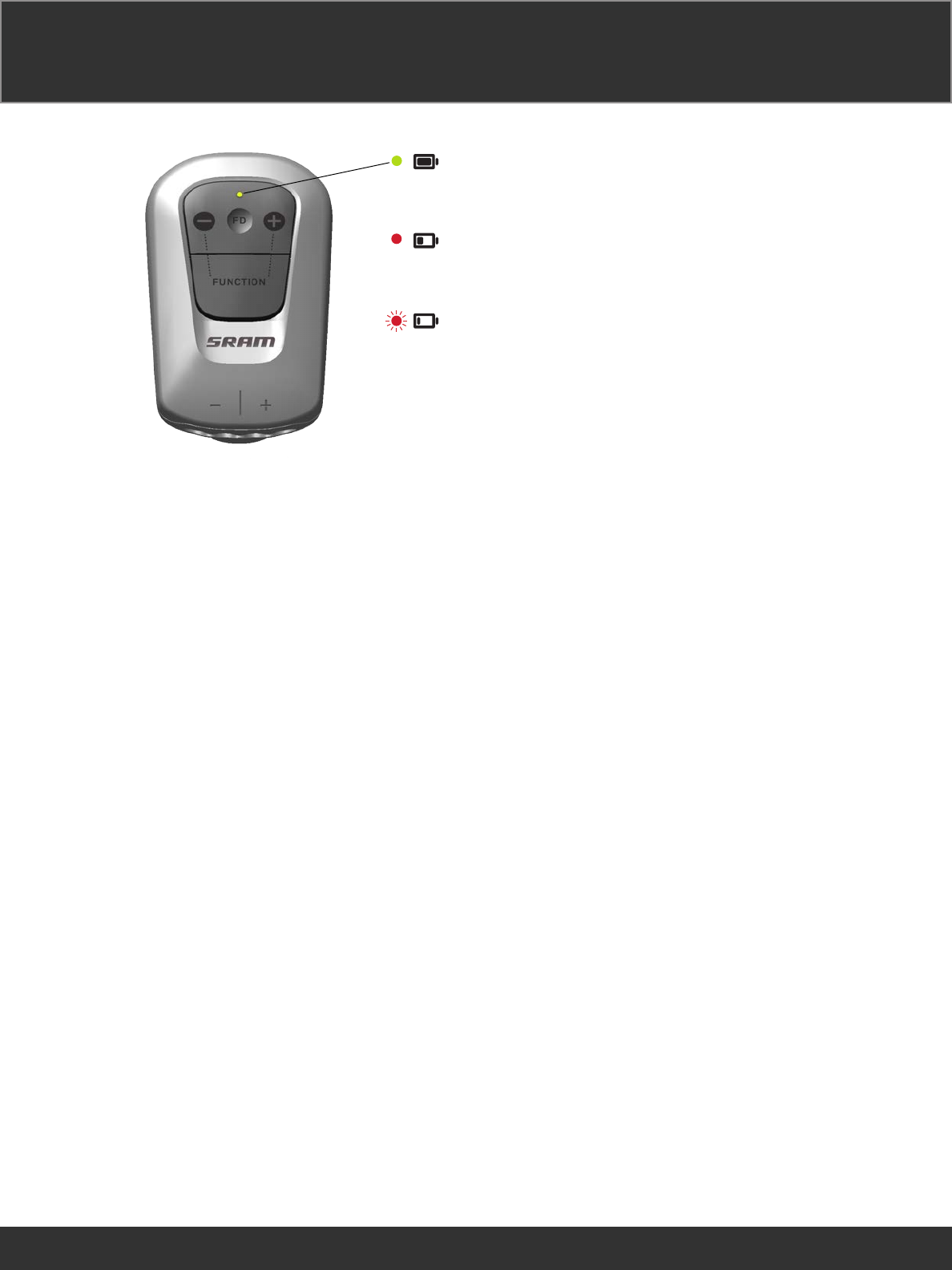
12-3 months
12-3 Monate
12-3 meses
24 à 6 mois
12-3 mesi
12-3 maanden
12-3 meses
12~3 か月
12-3 月
3-1 months
3-1 Monate
3-1 mes
6 à 1 mois
3-1 mesi
3-1 maanden
3-1 meses
3~1 か月
3-1 月
< 1 month
< 1 Monat
< 1 mes
< 1 mois
< 1 mese
< 1 maand
< 1 mês
< 1 か月
< 1 月
The LED lights up when a shift is
performed. The color of the LED
indicates the ride time remaining.
Les LED s’allument à chaque fois que
vous passez une vitesse. La couleur de
la LED indique la durée d’autonomie
restante.
O LED acende quando se mete uma
mudança. A cor do LED indica o tempo
de ciclismo que lhe resta.
Die LED leuchtet auf, wenn ein
Schaltvorgang durchgeführt wird. Die
Farbe der LED gibt die verbleibende
Fahrzeit an.
Il LED si illumina durante un cambio.
Il colore del LED indica il tempo di
guida rimanente.
シフトを行うとLEDが点灯します。
LEDの色は、残りの乗車可能時間を示
しています。
El LED se enciende cada vez que se
realiza un cambio de marcha. El color
del LED indica el tiempo de marcha
restante.
De LED brandt wanneer wordt
geschakeld. De kleur van de LED geeft
de resterende fietstijd aan.
变 速 时,LED 会 亮 起。LED 的 颜 色 表 示
剩余的骑行时间。
35
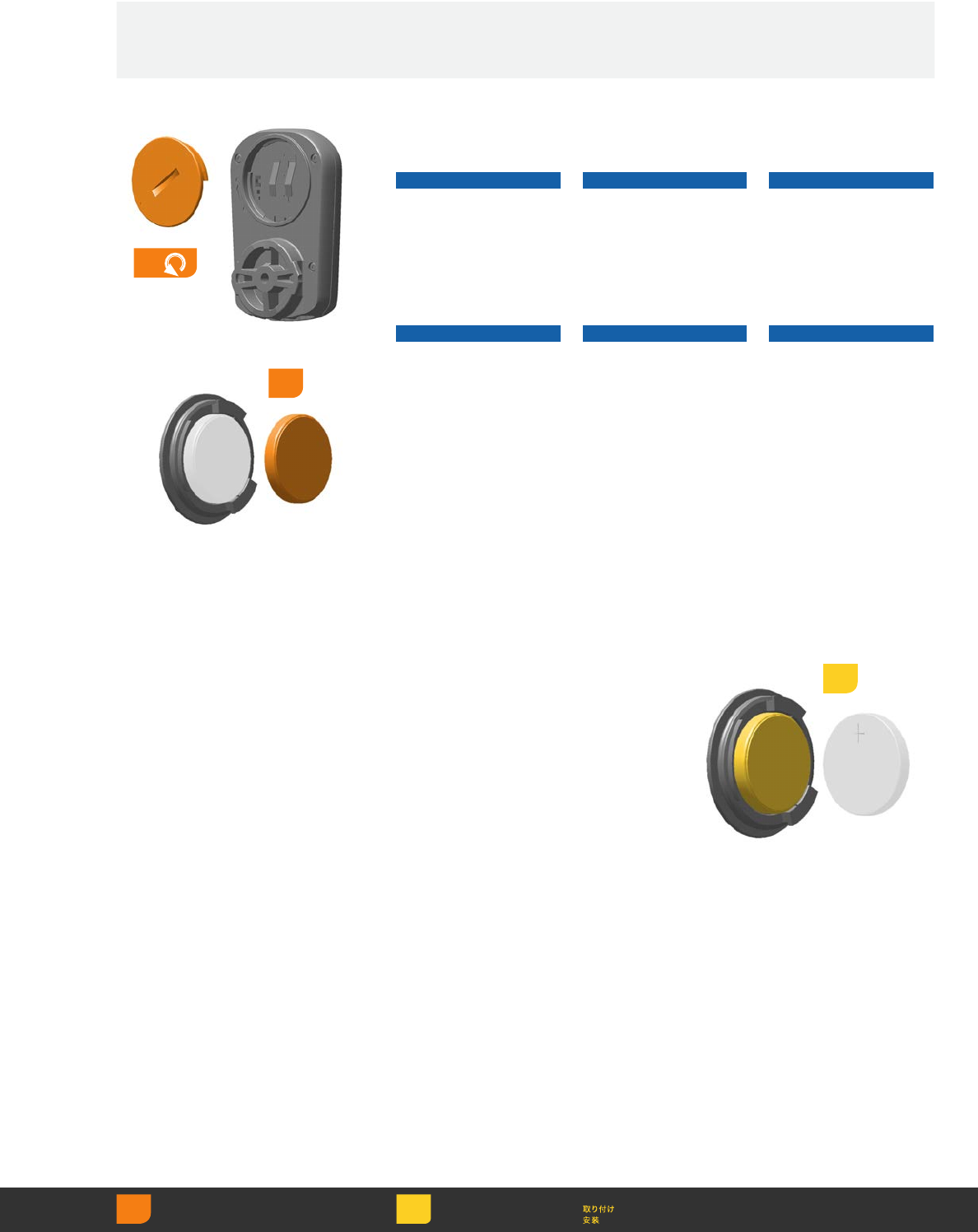
Insert a new CR2032
coin cell battery into the
battery cap, terminal
side out.
Insert a new CR2032
coin cell battery into the
battery cap, terminal
side out.
Insert a new CR2032
coin cell battery into the
battery cap, terminal
side out.
Insert a new CR2032
coin cell battery into the
battery cap, terminal
side out.
Insert a new CR2032
coin cell battery into the
battery cap, terminal
side out.
Insert a new CR2032
coin cell battery into the
battery cap, terminal
side out.
Insert a new CR2032
coin cell battery into the
battery cap, terminal
side out.
Insert a new CR2032
coin cell battery into the
battery cap, terminal
side out.
Insert a new CR2032
coin cell battery into the
battery cap, terminal
side out.
3
1
Use a coin to remove the
battery cap. Remove the
old battery.
NOTICE
Do not remove the
battery cap o-ring seal.
Use a coin to remove the
battery cap. Remove the
old battery.
NOTICE
Do not remove the
battery cap o-ring seal.
Use a coin to remove the
battery cap. Remove the
old battery.
NOTICE
Do not remove the
battery cap o-ring seal.
Use a coin to remove the
battery cap. Remove the
old battery.
NOTICE
Do not remove the
battery cap o-ring seal.
Use a coin to remove the
battery cap. Remove the
old battery.
NOTICE
Do not remove the
battery cap o-ring seal.
Use a coin to remove the
battery cap. Remove the
old battery.
NOTICE
Do not remove the
battery cap o-ring seal.
Replacement Replacement Replacement
Replacement Replacement Replacement
Replacement Replacement Replacement
2
Remove Retirer Retirar
Entfernen Rimuovere 取り外し
Quitar Verwijderen 拆卸
Install
Einbauen
Instalación
Installer
Installare
Monteren
Instalar
36
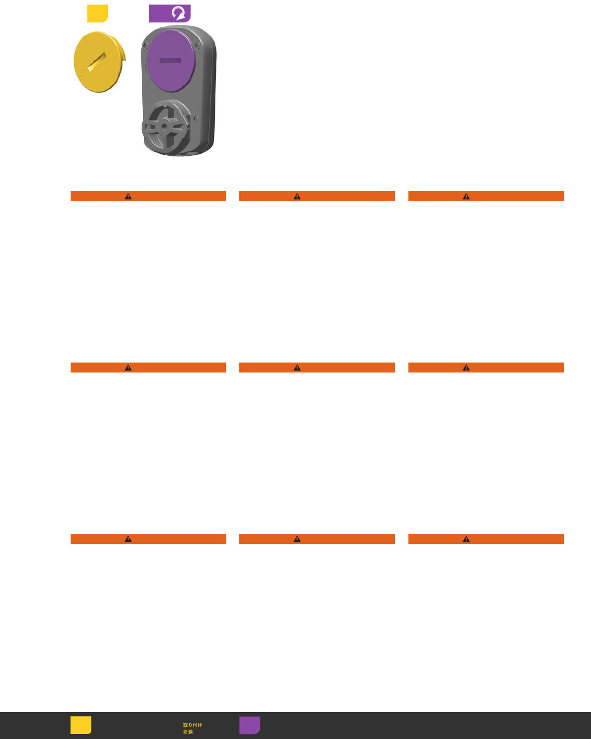
WARNING
Do not use sharp objects to
remove batteries.
Keep battery out of reach of children.
Do not put the battery in your mouth.
If ingested, seek medical
attention immediately.
Do not disassemble, damage, or
puncture the battery.
Consult the battery manufacturer for
safe handling instructions.
WARNING
Do not use sharp objects to
remove batteries.
Keep battery out of reach of children.
Do not put the battery in your mouth.
If ingested, seek medical
attention immediately.
Do not disassemble, damage, or
puncture the battery.
Consult the battery manufacturer for
safe handling instructions.
WARNING
Do not use sharp objects to
remove batteries.
Keep battery out of reach of children.
Do not put the battery in your mouth.
If ingested, seek medical
attention immediately.
Do not disassemble, damage, or
puncture the battery.
Consult the battery manufacturer for
safe handling instructions.
WARNING
Do not use sharp objects to
remove batteries.
Keep battery out of reach of children.
Do not put the battery in your mouth.
If ingested, seek medical
attention immediately.
Do not disassemble, damage, or
puncture the battery.
Consult the battery manufacturer for
safe handling instructions.
WARNING
Do not use sharp objects to
remove batteries.
Keep battery out of reach of children.
Do not put the battery in your mouth.
If ingested, seek medical
attention immediately.
Do not disassemble, damage, or
puncture the battery.
Consult the battery manufacturer for
safe handling instructions.
WARNING
Do not use sharp objects to
remove batteries.
Keep battery out of reach of children.
Do not put the battery in your mouth.
If ingested, seek medical
attention immediately.
Do not disassemble, damage, or
puncture the battery.
Consult the battery manufacturer for
safe handling instructions.
WARNING
Do not use sharp objects to
remove batteries.
Keep battery out of reach of children.
Do not put the battery in your mouth.
If ingested, seek medical
attention immediately.
Do not disassemble, damage, or
puncture the battery.
Consult the battery manufacturer for
safe handling instructions.
WARNING
Do not use sharp objects to
remove batteries.
Keep battery out of reach of children.
Do not put the battery in your mouth.
If ingested, seek medical
attention immediately.
Do not disassemble, damage, or
puncture the battery.
Consult the battery manufacturer for
safe handling instructions.
WARNING
Do not use sharp objects to
remove batteries.
Keep battery out of reach of children.
Do not put the battery in your mouth.
If ingested, seek medical
attention immediately.
Do not disassemble, damage, or
puncture the battery.
Consult the battery manufacturer for
safe handling instructions.
Reinstall the battery cap.
Use a coin and turn the
cap clockwise to lock it
into place.
Reinstall the battery cap.
Use a coin and turn the
cap clockwise to lock it
into place.
Reinstall the battery cap.
Use a coin and turn the
cap clockwise to lock it
into place.
Reinstall the battery cap.
Use a coin and turn the
cap clockwise to lock it
into place.
Reinstall the battery cap.
Use a coin and turn the
cap clockwise to lock it
into place.
Reinstall the battery cap.
Use a coin and turn the
cap clockwise to lock it
into place.
Reinstall the battery cap.
Use a coin and turn the
cap clockwise to lock it
into place.
Reinstall the battery cap.
Use a coin and turn the
cap clockwise to lock it
into place.
Reinstall the battery cap.
Use a coin and turn the
cap clockwise to lock it
into place.
45
Install
Einbauen
Instalación
Installer
Installare
Monteren
Instalar Adjust Régler Ajustar
Einstellen Regolare 調節
Ajustar Afstellen 调节

37
Maintenance Maintenance Maintenance
Maintenance Maintenance Maintenance
Maintenance Maintenance Maintenance
Periodic cleaning is recommended.
Use a damp cloth to wipe the
components until clean.
Periodically inspect each Blip
connector wire for damage. Replace
the Blip if the wire is damaged.
Periodic cleaning is recommended.
Use a damp cloth to wipe the
components until clean.
Periodically inspect each Blip
connector wire for damage. Replace
the Blip if the wire is damaged.
Periodic cleaning is recommended.
Use a damp cloth to wipe the
components until clean.
Periodically inspect each Blip
connector wire for damage. Replace
the Blip if the wire is damaged.
Periodic cleaning is recommended.
Use a damp cloth to wipe the
components until clean.
Periodically inspect each Blip
connector wire for damage. Replace
the Blip if the wire is damaged.
Periodic cleaning is recommended.
Use a damp cloth to wipe the
components until clean.
Periodically inspect each Blip
connector wire for damage. Replace
the Blip if the wire is damaged.
Periodic cleaning is recommended.
Use a damp cloth to wipe the
components until clean.
Periodically inspect each Blip
connector wire for damage. Replace
the Blip if the wire is damaged.
Periodic cleaning is recommended.
Use a damp cloth to wipe the
components until clean.
Periodically inspect each Blip
connector wire for damage. Replace
the Blip if the wire is damaged.
Periodic cleaning is recommended.
Use a damp cloth to wipe the
components until clean.
Periodically inspect each Blip
connector wire for damage. Replace
the Blip if the wire is damaged.
Periodic cleaning is recommended.
Use a damp cloth to wipe the
components until clean.
Periodically inspect each Blip
connector wire for damage. Replace
the Blip if the wire is damaged.

38
WARNING
Do not use or clean the BlipBox or
eTap™ shifters without connector wires
or dummy plugs installed. Moisture will
damage the electronics.
Avoid using or storing the device in
excessive heat or cold.
Avoid chemical cleaners and solvents
that can damage plastic components.
Do not submerge the BlipBox in liquid
of any kind.
Do not clean the BlipBox with a
power washer.

39
For consumers in the United States
and Canada, SRAM has partnered
with the Rechargeable Battery
Recycling Corporation. Please call
1-800-8-BATTERY or visit
www.rbrc.org for additional
information.
Replace the battery with an authentic
SRAM replacement battery only.
Used batteries must be recycled in
accordance with local and federal
government regulations.
WARNING
Do not place batteries in a fire.
For consumers in the United States
and Canada, SRAM has partnered
with the Rechargeable Battery
Recycling Corporation. Please call
1-800-8-BATTERY or visit
www.rbrc.org for additional
information.
Replace the battery with an authentic
SRAM replacement battery only.
Used batteries must be recycled in
accordance with local and federal
government regulations.
WARNING
Do not throw batteries in a fire.
For consumers in the United States
and Canada, SRAM has partnered
with the Rechargeable Battery
Recycling Corporation. Please call
1-800-8-BATTERY or visit
www.rbrc.org for additional
information.
Replace the battery with an authentic
SRAM replacement battery only.
Used batteries must be recycled in
accordance with local and federal
government regulations.
WARNING
Do not place batteries in a fire.
For consumers in the United States
and Canada, SRAM has partnered
with the Rechargeable Battery
Recycling Corporation. Please call
1-800-8-BATTERY or visit
www.rbrc.org for additional
information.
Replace the battery with an authentic
SRAM replacement battery only.
Used batteries must be recycled in
accordance with local and federal
government regulations.
WARNING
Do not place batteries in a fire.
Recycling Recycling Recycling
Recycling Recycling Recycling
Recycling Recycling Recycling

40
Compliance Compliance Compliance
Compliance Compliance Compliance
Compliance Compliance Compliance
SRAM LLC certifies that this product and its packaging are in compliance with:
R&TTE Directive, the Radio and Telecommunication Terminal Equipment Directive 1999/5/EC
WEEE Directive, the Waste Electrical and Electronic Equipment Directive 2012/19/EU
RoHS Directive, the restriction of the use of certain hazardous substances in electrical and electronic equipment 2002/95/
EC
REACh Directive, the Regulation on Registration, Evaluation, Authorization and Restriction of Chemical Directive 1907/2006/
EC
Batteries and Accumulators and Waste Batteries and Accumulators Directive 2006/66/EU
This device complies with Part 15 of the FCC Rules. Operation is subject to the following two conditions: (1) this device may
not cause harmful interference, and (2) this device must accept any interference received, including interference that may
cause undesired operation.
Note: This equipment has been tested and found to comply with the limits for a Class B digital device, pursuant to part 15
of the FCC Rules. These limits are designed to provide reasonable protection against harmful interference in a residential
installation. This equipment generates, uses and can radiate radio frequency energy and, if not installed and used in
accordance with the instructions, may cause harmful interference to radio communications. However, there is no guarantee
that interference will not occur in a particular installation. If this equipment does cause harmful interference to radio or
television reception, which can be determined by turning the equipment off and on, the user is encouraged to try to correct
the interference by one or more of the following measures:
• Reorient or relocate the receiving antenna.
• Increase the separation between the equipment and receiver.
• Connect the equipment into an outlet on a circuit different from that to which the receiver is connected.
• Consult the dealer or an experienced radio/TV technician for help.
This device complies with Industry Canada’s license-exempt RSS standard(s). Operation is subject to the following
two conditions: (1) this device may not cause interference, and (2) this device must accept any interference, including
interference that may cause undesired operation of the device.
The term “IC:” before the radio certification number only signifies that Industry Canada technical specifications were met.
Canadian Department of Communications Compliance Statement:
Firmware Update Dongle - DOC: CAN ICES-3(B)/NMB-3(B) C
Le présent appareil est conforme aux CNR d'Industrie Canada applicables aux appareils radio exempts de licence.
L'exploitation est autorisée aux deux conditions suivantes : (1) l'appareil ne doit pas produire de brouillage, et (2) l'utilisateur
de l'appareil doit accepter tout brouillage radioélectrique subi, même si le brouillage est susceptible d'en compromettre le
fonctionnement.
Warning: Any changes or modifications not expressively approved by SRAM could void the user's authority to operate this
equipment.
This product is ANT+ certified and complies with the bicycle power ANT+ Device Profile. For a complete listing of ANT+
Certified Products and their specific interoperability, please visit www.thisisant.com.
SRAM LLC WORLD HEADQUARTERS
1000 W. Fulton Market, 4th Floor
Chicago, Illinois 60607
USA
Left Shifter
Model#:00001
FCC ID: C9O-LSBED
IC: 10161A-LSBED
Right Shifter
Model#:00101
FCC ID: C9O-RSBED
IC: 10161A-RSBED
BlipBox
Model#:00201
FCC ID: C9O-BOXED
IC: 10161A-BOXED
Firmware Update Dongle
Model#:12701
FCC ID: C9O-LINKED
IC: 10161A-LINKED
Front Derailleur
Model#:12801
FCC ID: C9O-FDED
IC: 10161A-FDED
Rear Derailleur
Model#:12901
FCC ID: C9O-RDED
IC: 10161A-RDED

41
Specifications Specifications Specifications
Specifications Specifications Specifications
Specifications Specifications Specifications
Rechargeable Lithium-ion Polymer Battery Model: 25401
Cell Type 300mAh/3.7V
Pack Configuration 2S1P
Nominal Voltage 7.4 DC
EOD Voltage 6.0V DC
Nominal Capacity 300mAh
Minimum Capacity 290mAh
(at 0.2C discharge rate 3.0v cut off after standard charge)
Average Working Voltage 7.4V at 0.2C rate
Fast Charge Constant current 1.0C
Constant Voltage 8.4V
Operating Temperature Range
Standard Charge 32° to 114°F / 0° to 45°C
Discharge -4° to 140°F / -20° to 60°C
Weight of Battery Approx 6.5 g
Cell Dimension
Length Max.30.0mm
Width Max. 19.0mm
Thickness Max. Thickness: Max. 6.0mm
Storage at 50% SOC and specified temp, recoverable capacities in % vs. time.
-20° to 25°C (12 months, 85% ) 25° to 45°C (3 months, 80% )
60° to 70°C (1 hour, 85% )) 70° to 85°C (1 hour, 80% )
Battery Charger Model: 25301
The charger is designed to meet EMI safety standards for use in information technology equipment.
Rated Input Voltage 5V DC
Maximum Rated Output Voltage 8.4V
Operating Temperature Range 32°F to 104°F / 0°C to 40°C
Non-operating Temperature Range 50° to 140°F / 10°C to 60°
Relative Humidity for Operating and Non-operating 10% to 80%
Replacable Lithium Coin Cell Battery CR2032
Consult the battery manufacturer's instructions for technical information.

42
“We will revolutionize the relationship that our users have with SRAM products,
cultivating a bond between the rider and bicycle. Our technical communication
will be delivered in innovative and exciting ways, with deliberation and accuracy
that inspires loyalty and trust across the globe.”
-SRAM TechCom Vision Statement
ASIAN HEADQUARTERS
SRAM Taiwan
No. 1598-8 Chung Shan Road
Shen Kang Hsiang, Taichung City
Taiwan R.O.C.
WORLD HEADQUARTERS
SRAM LLC
1000 W. Fulton Market, 4th Floor
Chicago, Illinois 60607
USA
EUROPEAN HEADQUARTERS
SRAM Europe
Paasbosweg 14-16
3862ZS Nijkerk
The Netherlands
www.sram.com