SRM Service Center PM7 PowerMeter 7 User Manual SRM PC7 SHORTMANUAL 20100209 BW GERMAN

SRM Service Center, Inc. PowerMeter 7 SRM PC7 SHORTMANUAL 20100209 BW GERMAN

user manual

Training Systemwww.SRM.dePowerMeter 7PowerControl 7Short Manual
SRM Training SystemWireless PowerMeter 7Wireless PowerControl 7Quick Start GuideVersion: Nov 16, 2010A complete manual is available at http://www.srm.de
..Buttons and Views . . . . . . . . . . . . . . . . . . . . . . . . . . . . . . .5Installation of the SRM Training SystemCadence Magnet  . . . . . . . . . . . . . . . . . . . . . . . . . . . . . 7PowerMeter and Sensor Alignment  . . . . . . . . . . . . . . . 8Speed Transmitter and Handlebar Clip  . . . . . . . . . . . . 9Wake up from Sleep Mode . . . . . . . . . . . . . . . . . . . . . . . 10Real-Time Training Data Menu . . . . . . . . . . . . . . . . . . . . 11Average Training Data Menu  . . . . . . . . . . . . . . . . . . . 12Maximum Training Data Menu  . . . . . . . . . . . . . . . . . . 13Time/Date Menu  . . . . . . . . . . . . . . . . . . . . . . . . . . . . . 14Sensor Pairing  . . . . . . . . . . . . . . . . . . . . . . . . . . . . . . . . 15Setting the Zero Offset / Altitude  . . . . . . . . . . . . . . . . . . .19Clear PC Display/ Battery Status / Total Training Menu  .20Setup Menu  . . . . . . . . . . . . . . . . . . . . . . . . . . . . . . . . . . .21SRM Software  . . . . . . . . . . . . . . . . . . . . . . . . . . . . . . . . .23FCC Compliance Declaration  . . . . . . . . . . . . . . . . . . . . .25
..short key press:-go to training zones-”+” in setup modelong key press:-enter pairing modeNote:Long key press is over 3 seconds, very long key press over 10 secondsshort key press:-start/end interval-”-” in setup modein pairing mode:-search sensorslong key press:-enter setup modeshort key press:-awake from sleep-change screen/itemlong key press:-back to main screenvery long key press:-enter sleep mode- Page  5-
...1. Remove your old cranks.2. Remove the allen bolt for thecable guide, leaving thecables in place. Some guidesare riveted or glued, or arenot present. Consult a technican or get your systeminstalled if you are uncertain.3. Loosen the cables so you canslide the cadence magnetunder the guide. Make surethe magnet faces the lid onthe back of the PowerMeter4. Align the magnet and cableguide to reinstall the bolt. Donot fully tighten. You will needto adjust it when testing thePowerControl (see page 8).- Page  7-
- Page  8-....1. Install your new PowerMeter and cranks according to the original manufacturer instructions. If a bottom bracketcame with your new PowerMeter you must install that.2. Adjust the cadence magnet so it is 3-5mm from thelid on the back of the PowerMeter.3. Tighten the cable guide bolt to fix the cadence magnet.4. The PowerMeter is ready to pair.
- Page  9-...1. Install front wheel skeweror fork mounted pod.2. Install the provided magnet onyour spokes so it passes within3-5mm of the speedtransmitter.3. Speed sensor is ready to pair.1. SRM provides handlebar clipsto mount PowerControls tovarious handlebars.2.  Mount the handlebar clip tothe right of the stem so theballs point forward and thescrew point upwards (aluminium model downwards).3.  Secure the handlebar clip withthe bolt. Do not overtight.
..In Sleep Mode the PowerControlshows the version of the firmwareinstalled.In this example the firmwareversion is June 21, 2010. Press  once to awake the PowerControl from Sleep Mode.Starting with generation 7, the PowerControl has an integrated motion sensor that activates the unit when motion is detected. ThePowerControl switches off into Sleep Mode automatically after threeminutes (can be changed through the computer software). The integrated motion sensor switches the unit on as long as it is notswitched off manually (see below). The PowerControl will not enterSleep Mode while it is receiving data from any of the sensors. Press  longer than 10 seconds to manually enter Sleep Modeand deactivate the integrated motion sensor. This is useful duringtransport. Press  once to awake the PowerControl fromSleep Mode and reactivate the integrated motion sensor.- Page  10 -
The real time training menushows real time data as theathlete trains. • Top Line: Training Time, Distance [miles or km], AscendingAltitude [feet or m], Pedaling Time or all four alternating.These can be changed using the provided SRM Software. • Middle Line: Power [Watt; kW >1000], Heartrate [bpm]. • Bottom Line: Training Zone or Intervall if started, Speed [km/h or miles/h], Cadence [rpm] . If no signal from a sensor is picked up, the display shows “-“ for thissensor instead of a number (i.e. “-“ under speed if the speed sensoris not working). Press  to change from real time to average training datamenu.- Page  11 -
The average training data menushows average data over thecurrent training file.• Top Line: Training Time, Distance, Actual Altitude, Pedaling Timeor all four alternating.• Middle Line: Power, Heartrate. • Bottom Line: Speed, Cadence. Press  to change from average to maximum training datamenu.- Page  12 -
The maximum training data menushows the maximum valuesrecorded during a trainingsession.• Top Line: Total mechanical energy expenditure in kilojoules [kJ](Estimating an efficiency of 25% riding the bike and a 4:1 ratioof kilojoules to kilocalories [Cal] this is approximately equivalentto the total energy burned by the athlete in kilocalories = Cal)
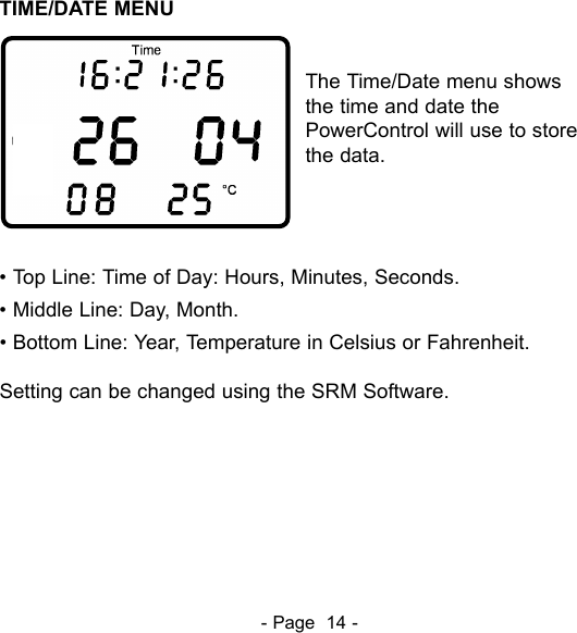
. • Middle Line: Maximum Power, Maximum Heartrate. • Bottom Line: Maximum Speed, Maximum Cadence. Press  to change from Maximum Training Data Menu toTime/Date Menu.- Page  13 -
The Time/Date menu shows the time and date thePowerControl will use to store the data.• Top Line: Time of Day: Hours, Minutes, Seconds. • Middle Line: Day, Month. • Bottom Line: Year, Temperature in Celsius or Fahrenheit.Setting can be changed using the SRM Software.- Page  14 -
- Page  15 -The PowerControl needs to be paired with the PowerMeter, SpeedSensor and Heartrate strap. The PowerControl will not receive datauntil it is paired. Pairing the sensors with the PowerControl is only possible if the sensors are switched on.1. Switch on the PowerMeter by pedaling the crank forwards a fewtimes (it will switch on when the magnet passes by). 2. Switch on the speed sensor by spinning the wheel. 3. Switch on heartrate sensor by putting the belt on your chest.Please moisten the electrodes to improve contact. 4. Switch on the PowerControl by pressing the  button. Hold for about 3 seconds to enter Sensor Pairing Mode. Press to start searching for the PowerMeter.The antenna symbol blinking on theright of the display shows that thesearching process has started. Thesearch bar in the middle of the dis-play shows the progress of thesearch. If no signal is picked up,make sure if the PowerMeter isswitched on (turn the crank) and the cadence magnet is 3-5mmaway from the PowerMeter lid. When the PowerMeter is found, thePowerControl will show ”Found” on the top line, alternating with theserial number. Press  then to confirm the PowerMeter.
Press  to select the next device (heartrate sensor).The PowerControl is initially set to"Suunto" heartrate sensors. Ifnecessary, press  to select"ANT+ Sport“ compatible sensors("PLUS" in the display) and press to start searching for it.The antenna symbol blinking onthe right of the display shows thatthe searching process has star-ted.The search bar in the middleof the display shows the progressof the search.If no signal is picked up, check if the sensor pads are well placedaround your chest and moistened. When the heartrate belt is found,the PowerControl will show ”Found” on the top line, alternating withthe serial number. Press  then to confirm this sensor. If theserial number of a sensor is known, this can be entered in the SRMsoftware in the setup menu under "special/hardware".Press  to select the next device (speed sensor). - Page 16 -
Turn the wheel with the magnet.The PowerControl is initially set to"Suunto" sensors. If necessary,press  to select "ANT+Sport" compatible sensors("PLUS" in the display) and press to start searching for it.The antenna symbol blinking onthe right of the display shows thatthe searching process has star-ted.The search bar in the middleof the display shows the progressof the search.If no signal is picked up, check if the pod is switched on and thewheel magnet is 3-5mm away from the pod. When the sensor isfound, the PowerControl will show ”Found” on the top line, alterna-ting with the serial number. Press  then to confirm this sensor.If the serial number of a sensor is known, this can be entered in theSRM software in the setup menu under "special/hardware". Press  switch to the pairing of a combined cadence / speedsensor (Garmin GSC10/Trek Duotrap).- Page 17 -
Turn the wheel or the crank withthe magnet. The PowerControl isinitially to speed only measurement("duo S").  If necessary, press to select combined speedand cadence ("duo SC") andpress  to start searching for it.The PowerMeter is disabled inthis case. The antenna symbolblinking on the right of the displayshows that the searching processhas started.The search bar in themiddle of the display shows theprogress of the search.If no signal is picked up, check if the pod is switched on and thewheel magnet is 3-5mm away from the pod. When the sensor isfound, the PowerControl will show ”Found” on the top line, alterna-ting with the serial number. Press  then to confirm this sensor.If the serial number of a sensor is known, this can be entered in theSRM software in the setup menu under "special/hardware".Press  for 3 seconds to return to the main menu.- Page 18 -
It is important to use the SRM Training System with a correct zerooffset, if not the measured powermay be wrong. The zero offset canbe set manually or automatically(by default). Turn the crank forwardto switch on the PowerMeter. Makesure there is no force on the crank.Press  and  at the sametime to enter the zero offset mode.The screen shows the real-time zero offset value on the middle line.The bottom line shows the previously stored zero offset. After the topnumber stabilizes, press  to store the new zero offset. If it remainszero, the PowerControl is not receiving any signal from the Power-Meter. Make sure the PowerMeter is turned on and paired correctly.  .Pressing .once more showsthe altitude menu where the abso-lute altitude can be set using (+) and  (-). Pressing again returns to the main screen.You can select metric or Englishunits using the SRM Software forboth Altitude and Speed.- Page  19 -
.To clear the PowerControl display and start a new training pressand simultaneouslyThe stored data of previous rides willnot be lost and can still be downloaded with the SRM Software..The PowerControl can be chargedusing the supplied charger or anyUSB port. The battery has nomemory effect and can be char gedregularly. Press .and simultaneously to check batterystatus. It is full with a voltage over4.00V and empty under 3.60V..Press .again to see thetotal amount of training:• Total distance (e.g. 998 km)• Total training hours (e.g. 38 h)• Total energy expenditure(e.g. 22,8906 Megajoule).will bring you back to main menu.  - Page  20 -
Hold for about 3 seconds to enter the Setup mode. The firstscreen shows the setup menu to change the time and date.The blinking digit can be changed(seconds, minutes, hours, day,month, year). Press  toincrease or  to decreasethe shown digit. Press  toproceed to the next digit untilyear. After the last digit (year) the next screen shows the manual setupmenu for the slope which is a unique value for each PowerMeter.“Aut” tells the PowerControl topick up the slope automaticallyfrom the PowerMeter.Press .or  during thisscreen to manually enter a slopebetween 15.0 and 50.0 Hz/Nm. To set the slope to ”Aut” go to 15.0 and hit or go to 50.0 andhit once.- Page  21 -
The third screen shows the setupmenu for the wheel circumferencein millimeters [mm]. Press  toincrease or  to decrease thevalue of the flashing digit. Pressto select each of the next3 digits, then proceed to the nextscreen. The fourth screen showsthe setup menu for data storageinterval. The storage interval canbe set between 0.5 and 5.0 sec.By increasing or decreasing.the storage interval, theavailable  memory shown on thebottom line changes from 65 to655 hours.The fifth screen sets the variableto be used for training zones:heart rate [bpm] or power [watts].The sixth to tenth screens definethe limits for each training zone.Hold for more than threeseconds to return to the mainmenu. - Page  22 -
- Page  23 -To download your training files and setup the PowerControl usingyour computer, use the supplied CD or download the SRM Softwareat www.srm.de and install it at Windows 2000, XP, Vista andWindows 7 computer. The SRM software installer will offer thefollowing choices:1. Standard setupWill install the SRM Softwarewith drivers for PC VI and 7.2. Software only (for Updates)Will install only the SRMSoftware without drivers.3. Software and all driversWill install the SRM Softwarewith drivers for PC IV, V andPC VI, 7.If needed, the software and drivers are also available separately onthe supplied CD or at www.srm.de.
Plug in the PowerControl with the Mini USB cable. Once the PC7 isattached and recognized, the drop-down box with PC7 will grey out.Enter your name or initials, interval of storage (seconds). Make surethe ”automatic” box is checked, so the PowerControl will pick uppreprogrammed slope from the PowerMeter automatically. Tomanually enter the slope, uncheck the ”automatic” box. Entercircumference of tire (2095mm is the default). To make your speedand distance accurate, do a roll-out and enter this number inmillimeters. Clicking the ”Special” button, will allow you to customizeyour top line display, turn on or off Training Zones and change unitsfrom metric to English.To setup your PowerControl press the SetupButton.- Page  24 -To download your training pressthe download button.
- Page  25 -Regulatory Compliance FCC ID: WCS-PM7 IC: 7761A-PM7Regulatory Compliance FCC ID: WCS-PC7 IC: 7761A-PC7This device complies with part 15 of the FCC Rules, IndustryCanada RSS-210, and ICES-003. Operation is subjectto the following two conditions:1. this device may not cause harmful interference, and2. this device must accept any interference received, includinginterference that may cause undesired operation.This equipment has been tested and found to comply with the limitsfor a Class B digital device, pursuant to part 15 of the FCC rules.These limits are designed to provide reasonable protection againstharmful interference in a residential installation. This equipmentgenerates, uses, and can radiate radio frequency energy and maycause harmful interference to radio communications if not installedand used  in accordance with the instructions.However, there is no guarantee that interference will not occur in aparticular installation. If this equipment does cause harmfulinterference to radio or television reception, which can be determined by turning the equipment off and on, the user is
encouraged to try to correct the interference by one of the followingmeasures:• Reorient or relocate the receiving antenna.• Increase the separation between the equipmentand the receiver• Connect the equipment into an outlet that is on a different circuit from unit.• Consult the dealer or an experienced radio/TV technician for help.This product does not contain any user-serviceable parts. Repairsshould only be made by an authorized SRM service center.Unauthorized repairs or modifications could result in permanentdamage to the equipment, and void your warranty and yourauthority to operate this device under Part 15 regulations.- Page  26 -
'!$$%"##)' (,Rudolf Schulten Str. 6            52428 Jülich / Germany            Tel: +49 2461 69123 0         Fax: +49 2461 69123 17#)+%"##(*#)("720 West Monument StreetColorado Springs, CO 80904 / U.S.A.   Tel: +1 719 266 4127Fax: +1 719 266 4284* &% Via della Rimembranza, 72655100 Lucca / ItalyTel: +39 0583 332036Fax: +39 0583 331684http://www.srm.de

Navigation menu