SRM Service Center PM7 PowerMeter 7 User Manual SRM PC7 SHORTMANUAL 20100209 BW GERMAN
SRM Service Center, Inc. PowerMeter 7 SRM PC7 SHORTMANUAL 20100209 BW GERMAN
user manual

Training System
www.SRM.de
PowerMeter 7
PowerControl 7
Short Manual

SRM Training System
Wireless PowerMeter 7
Wireless PowerControl 7
Quick Start Guide
Version: Nov 16, 2010
A complete manual is available at http://www.srm.de

..
Buttons and Views . . . . . . . . . . . . . . . . . . . . . . . . . . . . . . .5
Installation of the SRM Training System
Cadence Magnet . . . . . . . . . . . . . . . . . . . . . . . . . . . . . 7
PowerMeter and Sensor Alignment . . . . . . . . . . . . . . . 8
Speed Transmitter and Handlebar Clip . . . . . . . . . . . . 9
Wake up from Sleep Mode . . . . . . . . . . . . . . . . . . . . . . . 10
Real-Time Training Data Menu . . . . . . . . . . . . . . . . . . . . 11
Average Training Data Menu . . . . . . . . . . . . . . . . . . . 12
Maximum Training Data Menu . . . . . . . . . . . . . . . . . . 13
Time/Date Menu . . . . . . . . . . . . . . . . . . . . . . . . . . . . . 14
Sensor Pairing . . . . . . . . . . . . . . . . . . . . . . . . . . . . . . . . 15
Setting the Zero Offset / Altitude . . . . . . . . . . . . . . . . . . .19
Clear PC Display/ Battery Status / Total Training Menu .20
Setup Menu . . . . . . . . . . . . . . . . . . . . . . . . . . . . . . . . . . .21
SRM Software . . . . . . . . . . . . . . . . . . . . . . . . . . . . . . . . .23
FCC Compliance Declaration . . . . . . . . . . . . . . . . . . . . .25
..
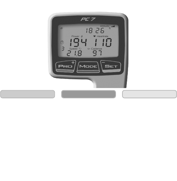
short key press:
-go to training zones
-”+” in setup mode
long key press:
-enter pairing mode
Note:
Long key press is over 3 seconds, very long key press over 10 seconds
short key press:
-start/end interval
-”-” in setup mode
in pairing mode:
-search sensors
long key press:
-enter setup mode
short key press:
-awake from sleep
-change screen/item
long key press:
-back to main screen
very long key press:
-enter sleep mode
- Page 5-
...
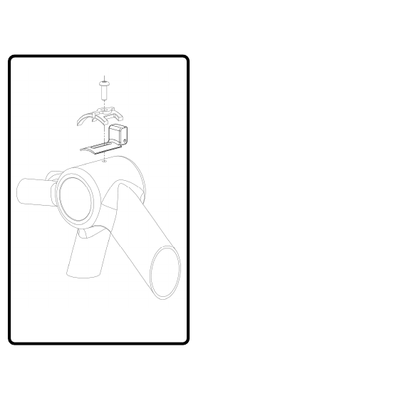
1. Remove your old cranks.
2. Remove the allen bolt for the
cable guide, leaving the
cables in place. Some guides
are riveted or glued, or are
not present. Consult a
technican or get your system
installed if you are uncertain.
3. Loosen the cables so you can
slide the cadence magnet
under the guide. Make sure
the magnet faces the lid on
the back of the PowerMeter
4. Align the magnet and cable
guide to reinstall the bolt. Do
not fully tighten. You will need
to adjust it when testing the
PowerControl (see page 8).
- Page 7-
- Page 8-
...
.
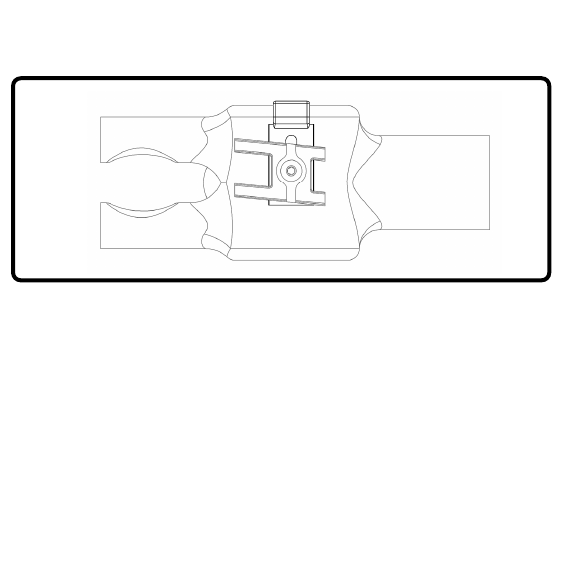
1. Install your new PowerMeter and cranks according to the
original manufacturer instructions. If a bottom bracket
came with your new PowerMeter you must install that.
2. Adjust the cadence magnet so it is 3-5mm from the
lid on the back of the PowerMeter.
3. Tighten the cable guide bolt to fix the cadence magnet.
4. The PowerMeter is ready to pair.
- Page 9-
...
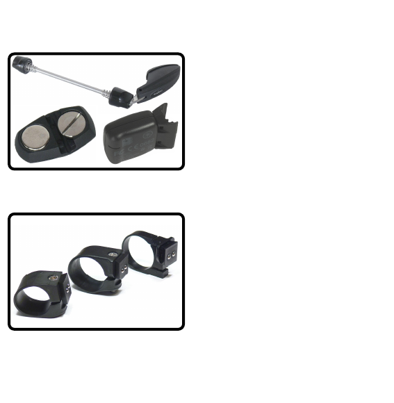
1. Install front wheel skewer
or fork mounted pod.
2. Install the provided magnet on
your spokes so it passes within
3-5mm of the speed
transmitter.
3. Speed sensor is ready to pair.
1. SRM provides handlebar clips
to mount PowerControls to
various handlebars.
2. Mount the handlebar clip to
the right of the stem so the
balls point forward and the
screw point upwards
(aluminium model downwards).
3. Secure the handlebar clip with
the bolt. Do not overtight.
..
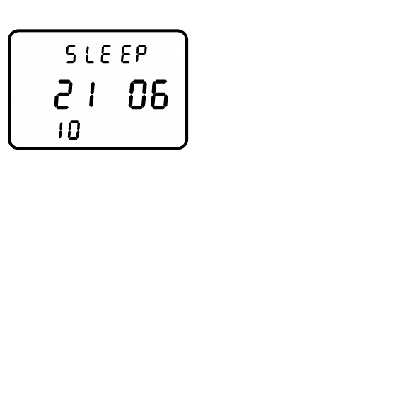
In Sleep Mode the PowerControl
shows the version of the firmware
installed.
In this example the firmware
version is June 21, 2010.
Press once to awake the PowerControl from Sleep Mode.
Starting with generation 7, the PowerControl has an integrated
motion sensor that activates the unit when motion is detected. The
PowerControl switches off into Sleep Mode automatically after three
minutes (can be changed through the computer software). The
integrated motion sensor switches the unit on as long as it is not
switched off manually (see below). The PowerControl will not enter
Sleep Mode while it is receiving data from any of the sensors.
Press longer than 10 seconds to manually enter Sleep Mode
and deactivate the integrated motion sensor. This is useful during
transport. Press once to awake the PowerControl from
Sleep Mode and reactivate the integrated motion sensor.
- Page 10 -
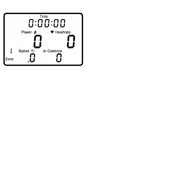
The real time training menu
shows real time data as the
athlete trains.
• Top Line: Training Time, Distance [miles or km], Ascending
Altitude [feet or m], Pedaling Time or all four alternating.
These can be changed using the provided SRM Software.
• Middle Line: Power [Watt; kW >1000], Heartrate [bpm].
• Bottom Line: Training Zone or Intervall if started,
Speed [km/h or miles/h], Cadence [rpm] .
If no signal from a sensor is picked up, the display shows “-“ for this
sensor instead of a number (i.e. “-“ under speed if the speed sensor
is not working).
Press to change from real time to average training data
menu.
- Page 11 -
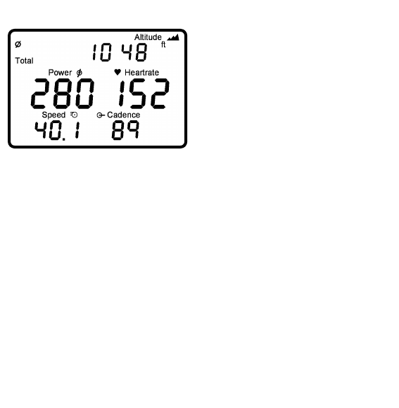
The average training data menu
shows average data over the
current training file.
• Top Line: Training Time, Distance, Actual Altitude, Pedaling Time
or all four alternating.
• Middle Line: Power, Heartrate.
• Bottom Line: Speed, Cadence.
Press to change from average to maximum training data
menu.
- Page 12 -
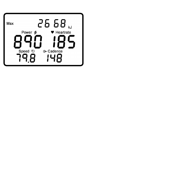
The maximum training data menu
shows the maximum values
recorded during a training
session.
• Top Line: Total mechanical energy expenditure in kilojoules [kJ]
(Estimating an efficiency of 25% riding the bike and a 4:1 ratio
of kilojoules to kilocalories [Cal] this is approximately equivalent
to the total energy burned by the athlete in kilocalories = Cal).
• Middle Line: Maximum Power, Maximum Heartrate.
• Bottom Line: Maximum Speed, Maximum Cadence.
Press to change from Maximum Training Data Menu to
Time/Date Menu.
- Page 13 -
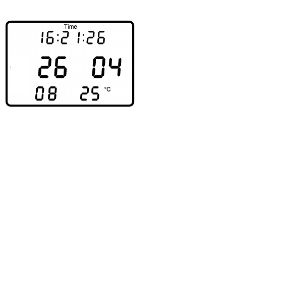
The Time/Date menu shows
the time and date the
PowerControl will use to store
the data.
• Top Line: Time of Day: Hours, Minutes, Seconds.
• Middle Line: Day, Month.
• Bottom Line: Year, Temperature in Celsius or Fahrenheit.
Setting can be changed using the SRM Software.
- Page 14 -
- Page 15 -
The PowerControl needs to be paired with the PowerMeter, Speed
Sensor and Heartrate strap. The PowerControl will not receive data
until it is paired. Pairing the sensors with the PowerControl is only
possible if the sensors are switched on.
1. Switch on the PowerMeter by pedaling the crank forwards a few
times (it will switch on when the magnet passes by).
2. Switch on the speed sensor by spinning the wheel.
3. Switch on heartrate sensor by putting the belt on your chest.
Please moisten the electrodes to improve contact.
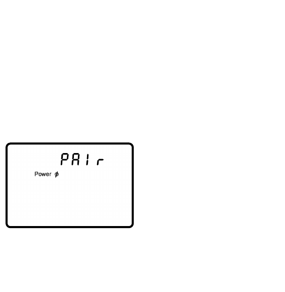
4. Switch on the PowerControl by pressing the button.
Hold for about 3 seconds to enter Sensor Pairing Mode. Press
to start searching for the PowerMeter.
The antenna symbol blinking on the
right of the display shows that the
searching process has started. The
search bar in the middle of the dis-
play shows the progress of the
search. If no signal is picked up,
make sure if the PowerMeter is
switched on (turn the crank) and the cadence magnet is 3-5mm
away from the PowerMeter lid. When the PowerMeter is found, the
PowerControl will show ”Found” on the top line, alternating with the
serial number. Press then to confirm the PowerMeter.
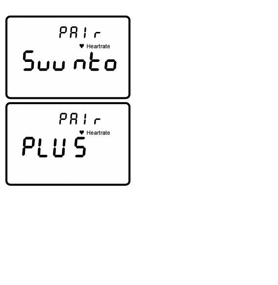
Press to select the next device (heartrate sensor).
The PowerControl is initially set to
"Suunto" heartrate sensors. If
necessary, press to select
"ANT+ Sport“ compatible sensors
("PLUS" in the display) and press
to start searching for it.
The antenna symbol blinking on
the right of the display shows that
the searching process has star-
ted.The search bar in the middle
of the display shows the progress
of the search.
If no signal is picked up, check if the sensor pads are well placed
around your chest and moistened. When the heartrate belt is found,
the PowerControl will show ”Found” on the top line, alternating with
the serial number. Press then to confirm this sensor. If the
serial number of a sensor is known, this can be entered in the SRM
software in the setup menu under "special/hardware".
Press to select the next device (speed sensor).
- Page 16 -
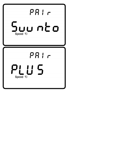
Turn the wheel with the magnet.
The PowerControl is initially set to
"Suunto" sensors. If necessary,
press to select "ANT+
Sport" compatible sensors
("PLUS" in the display) and press
to start searching for it.
The antenna symbol blinking on
the right of the display shows that
the searching process has star-
ted.The search bar in the middle
of the display shows the progress
of the search.
If no signal is picked up, check if the pod is switched on and the
wheel magnet is 3-5mm away from the pod. When the sensor is
found, the PowerControl will show ”Found” on the top line, alterna-
ting with the serial number. Press then to confirm this sensor.
If the serial number of a sensor is known, this can be entered in the
SRM software in the setup menu under "special/hardware".
Press switch to the pairing of a combined cadence / speed
sensor (Garmin GSC10/Trek Duotrap).
- Page 17 -
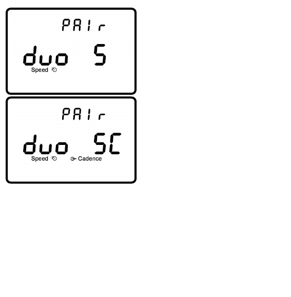
Turn the wheel or the crank with
the magnet. The PowerControl is
initially to speed only measurement
("duo S"). If necessary, press
to select combined speed
and cadence ("duo SC") and
press to start searching for it.
The PowerMeter is disabled in
this case. The antenna symbol
blinking on the right of the display
shows that the searching process
has started.The search bar in the
middle of the display shows the
progress of the search.
If no signal is picked up, check if the pod is switched on and the
wheel magnet is 3-5mm away from the pod. When the sensor is
found, the PowerControl will show ”Found” on the top line, alterna-
ting with the serial number. Press then to confirm this sensor.
If the serial number of a sensor is known, this can be entered in the
SRM software in the setup menu under "special/hardware".
Press for 3 seconds to return to the main menu.
- Page 18 -
It is important to use the SRM Training System with a correct zero
offset, if not the measured power
may be wrong. The zero offset can
be set manually or automatically
(by default). Turn the crank forward
to switch on the PowerMeter. Make
sure there is no force on the crank.
Press and at the same
time to enter the zero offset mode.
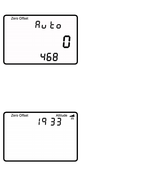
The screen shows the real-time zero offset value on the middle line.
The bottom line shows the previously stored zero offset. After the top
number stabilizes, press to store the new zero offset. If it remains
zero, the PowerControl is not receiving any signal from the Power-
Meter. Make sure the PowerMeter is turned on and paired correctly.
.
Pressing .once more shows
the altitude menu where the abso-
lute altitude can be set using
(+) and (-). Pressing
again returns to the main screen.
You can select metric or English
units using the SRM Software for
both Altitude and Speed.
- Page 19 -
.
To clear the PowerControl display and start a new training press
and simultaneouslyThe stored data of previous rides will
not be lost and can still be downloaded with the SRM Software.
.
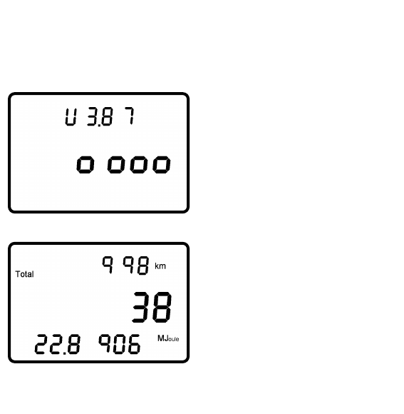
The PowerControl can be charged
using the supplied charger or any
USB port. The battery has no
memory effect and can be char ged
regularly. Press .and
simultaneously to check battery
status. It is full with a voltage over
4.00V and empty under 3.60V.
.
Press .again to see the
total amount of training:
• Total distance (e.g. 998 km)
• Total training hours (e.g. 38 h)
• Total energy expenditure
(e.g. 22,8906 Megajoule)
.will bring you back to main menu.
- Page 20 -
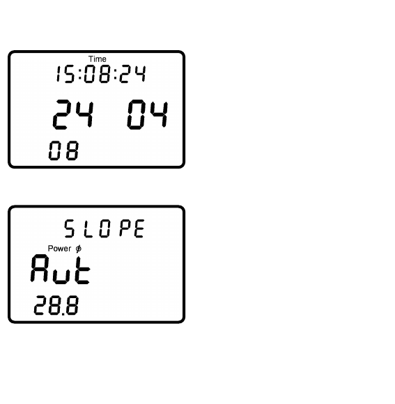
Hold for about 3 seconds to enter the Setup mode. The first
screen shows the setup menu to change the time and date.
The blinking digit can be changed
(seconds, minutes, hours, day,
month, year). Press to
increase or to decrease
the shown digit. Press to
proceed to the next digit until
year.
After the last digit (year) the next screen shows the manual setup
menu for the slope which is a unique value for each PowerMeter.
“Aut” tells the PowerControl to
pick up the slope automatically
from the PowerMeter.
Press .or during this
screen to manually enter a slope
between 15.0 and 50.0 Hz/Nm.
To set the slope to ”Aut” go to 15.0 and hit or go to 50.0 and
hit once.
- Page 21 -
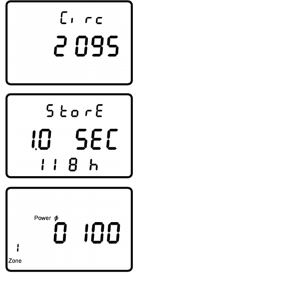
The third screen shows the setup
menu for the wheel circumference
in millimeters [mm]. Press to
increase or to decrease the
value of the flashing digit. Press
to select each of the next
3 digits, then proceed to the next
screen. The fourth screen shows
the setup menu for data storage
interval. The storage interval can
be set between 0.5 and 5.0 sec.
By increasing or decreasing
.the storage interval, the
available memory shown on the
bottom line changes from 65 to
655 hours.
The fifth screen sets the variable
to be used for training zones:
heart rate [bpm] or power [watts].
The sixth to tenth screens define
the limits for each training zone.
Hold for more than three
seconds to return to the main
menu.
- Page 22 -
- Page 23 -
To download your training files and setup the PowerControl using
your computer, use the supplied CD or download the SRM Software
at www.srm.de and install it at Windows 2000, XP, Vista and
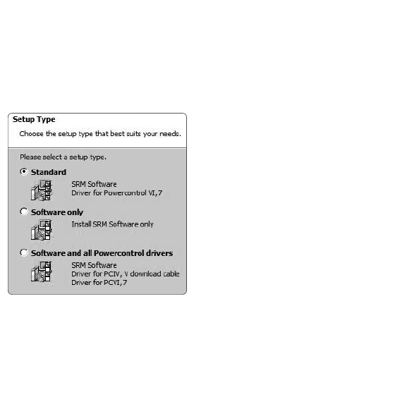
Windows 7 computer. The SRM software installer will offer the
following choices:
1. Standard setup
Will install the SRM Software
with drivers for PC VI and 7.
2. Software only (for Updates)
Will install only the SRM
Software without drivers.
3. Software and all drivers
Will install the SRM Software
with drivers for PC IV, V and
PC VI, 7.
If needed, the software and drivers are also available separately on
the supplied CD or at www.srm.de.
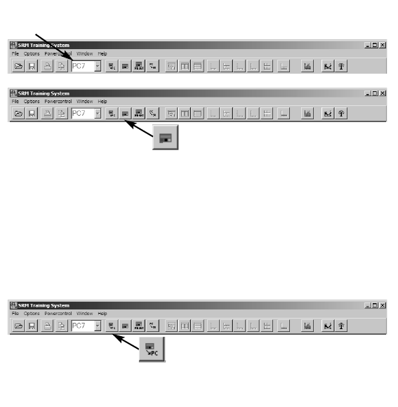
Plug in the PowerControl with the Mini USB cable. Once the PC7 is
attached and recognized, the drop-down box with PC7 will grey out.
Enter your name or initials, interval of storage (seconds). Make sure
the ”automatic” box is checked, so the PowerControl will pick up
preprogrammed slope from the PowerMeter automatically. To
manually enter the slope, uncheck the ”automatic” box. Enter
circumference of tire (2095mm is the default). To make your speed
and distance accurate, do a roll-out and enter this number in
millimeters. Clicking the ”Special” button, will allow you to customize
your top line display, turn on or off Training Zones and change units
from metric to English.
To setup your PowerControl press the Setup
Button.
- Page 24 -
To download your training press
the download button.

- Page 25 -
Regulatory Compliance FCC ID: WCS-PM7 IC: 7761A-PM7
Regulatory Compliance FCC ID: WCS-PC7 IC: 7761A-PC7
This device complies with part 15 of the FCC Rules, Industry
Canada RSS-210, and ICES-003. Operation is subject
to the following two conditions:
1. this device may not cause harmful interference, and
2. this device must accept any interference received, including
interference that may cause undesired operation.
This equipment has been tested and found to comply with the limits
for a Class B digital device, pursuant to part 15 of the FCC rules.
These limits are designed to provide reasonable protection against
harmful interference in a residential installation. This equipment
generates, uses, and can radiate radio frequency energy and may
cause harmful interference to radio communications if not installed
and used in accordance with the instructions.
However, there is no guarantee that interference will not occur in a
particular installation. If this equipment does cause harmful
interference to radio or television reception, which can be
determined by turning the equipment off and on, the user is

encouraged to try to correct the interference by one of the following
measures:
• Reorient or relocate the receiving antenna.
• Increase the separation between the equipment
and the receiver
• Connect the equipment into an outlet that is on a
different circuit from unit.
• Consult the dealer or an experienced radio/TV technician
for help.
This product does not contain any user-serviceable parts. Repairs
should only be made by an authorized SRM service center.
Unauthorized repairs or modifications could result in permanent
damage to the equipment, and void your warranty and your
authority to operate this device under Part 15 regulations.
- Page 26 -

'!$$%"##)' (,
Rudolf Schulten Str. 6
52428 Jülich / Germany
Tel: +49 2461 69123 0
Fax: +49 2461 69123 17
#)+%"##(*#)("
720 West Monument Street
Colorado Springs, CO 80904 / U.S.A.
Tel: +1 719 266 4127
Fax: +1 719 266 4284
* &%
Via della Rimembranza, 726
55100 Lucca / Italy
Tel: +39 0583 332036
Fax: +39 0583 331684
http://www.srm.de