SRT Marine Systems plc 4230002 AIS Coast Station User Manual Coast Station manual
Software Radio Technology plc AIS Coast Station Coast Station manual
User manual

CS100 AIS Coast Station Transceiver
Installation and operation manual
201-0413:7
SRT Marine System Solutions Ltd.
www.srt-marinesystems.com
support@srt-marinesystems.com

Page 1
1 Glossary...............................................................................................3
2 Notices.................................................................................................4
2.1 Safety warnings ................................................................................................................................. 4
2.2 General notices.................................................................................................................................. 4
2.3 Regulatory information....................................................................................................................... 5
3 Introduction.........................................................................................7
3.1 About AIS........................................................................................................................................... 7
3.2 Typical Coast Station system installation .......................................................................................... 8
3.3 Coast Station modes of operation ..................................................................................................... 9
3.4 Internal data logging .......................................................................................................................... 9
4 Connections and status indicators.................................................10
5 Installation and configuration..........................................................11
5.1 What’s in the box ............................................................................................................................. 11
5.2 Preparing for installation .................................................................................................................. 12
5.3 Network configuration ...................................................................................................................... 13
5.4 Resetting the Coast Station............................................................................................................. 15
6 Coast Station data communication protocol .................................16
6.1 Setting the Coast Station name ....................................................................................................... 16
6.2 Heartbeat output .............................................................................................................................. 17
6.3 Coast Station control sentences ...................................................................................................... 17
7 Configuration using proAtoN ..........................................................20
7.1 proAtoN Installation ......................................................................................................................... 20
7.2 Connection of the Coast Station to a PC ......................................................................................... 20
7.3 Application layout............................................................................................................................. 21
7.4 Transceiver configuration ................................................................................................................ 22
7.5 Transceiver diagnostics ................................................................................................................... 29
7.6 Other features.................................................................................................................................. 30
8 Technical specification ....................................................................31
8.1 Applicable equipment standards...................................................................................................... 31
8.2 AIS Transceiver specification .......................................................................................................... 31
8.3 Drawings and dimensions................................................................................................................ 33
9 Warranty ............................................................................................34
Table of contents

Page 2
Figure 1 The AIS network ........................................................................................................................... 7
Figure 2 Coast Station installation for connection to a remote viewer/database via Ethernet.................... 8
Figure 3 Coast Station installation for connection to a local viewer/database via Ethernet........................ 8
Figure 4 Coast Station installation for connection to a local viewer/database via USB .............................. 9
Figure 5 Coast Station connections.......................................................................................................... 10
Figure 6 What’s in the box - typical configuration ..................................................................................... 11
Figure 7 Coast Station network configuration home screen ..................................................................... 13
Figure 8 Configuration of Coast Station name in AIS receiver mode ....................................................... 17
Figure 9 proAtoN application layout.......................................................................................................... 21
Figure 10 proAtoN tab synchronisation icons ............................................................................................. 22
Figure 11 proAtoN message schedule tab layout....................................................................................... 24
Figure 12 Example FATDMA schedule....................................................................................................... 25
Figure 13 Example RATDMA schedule ...................................................................................................... 27
Figure 14 Virtual AtoN configuration tab layout .......................................................................................... 28
Figure 15 Transceiver dimensions.............................................................................................................. 33
List of figures

Glossary
Page 3
1 Glossary
AIS Automatic Identification System
AtoN Aid to Navigation
BIIT Built In Integrity Test
FATDMA Fixed Access Time Division Multiple Access
GLONASS Global Navigation Satellite System (term specific to the satellite navigation
system operated by the Russian Federation)
GNSS Global Navigation Satellite System (general term used to refer to any satellite
navigation system)
GPS Global Positioning System
IALA International Association of Lighthouse Authorities
IEC International Electrotechnical commission
ITU International Telecommunication Union
MID (in the context of
MMSI) Maritime Identification Digits
MMSI Maritime Mobile Service Identity
NMEA National Marine Electronics Association
RACON A radar transponder used to mark navigational hazards.
RATMDA Random Access Time Division Multiple Access
RS232 Serial data communications standard - see TIA-232-F
RS422 Serial data communications standard - see TIA-422-B
SART Search And Rescue Transponder
SOLAS Safety of Life at Sea
SDI-12 Serial Data Interface at 1200 Baud
USB Universal Serial Bus
UTC Coordinated Universal Time
VDL VHF Data Link
VHF Very High Frequency
VSWR Voltage Standing Wave Ratio

Notices
Page 4
2Notices
When reading this manual please pay particular attention to warnings marked with the
warning triangle symbol shown on the left. These are important messages for safety,
installation and usage of the transceiver.
2.1 Safety warnings
2.2 General notices
2.2.1 Position source
All marine Automatic Identification System (AIS) transceivers utilise a satellite based location system such as
the Global Positioning Satellite (GPS) network. The general term for satellite based location systems is Global
Navigation Satellite System or GPS. This manual refers to either GNSS or GPS depending on context.
2.2.2 Product category
This product is categorised as 'protected' in accordance with the definitions provided in IEC 60945.
2.2.3 Disposal of the product and packaging
Please dispose of this product in accordance with the European WEEE Directive or with the applicable local
regulations for disposal of electrical equipment. Every effort has been made to ensure the packaging for the
product is recyclable. Please dispose of the packaging in an environmentally friendly manner.
2.2.4 Accuracy of this manual
This manual is intended as a guide to the installation, setup and use of this product. Every effort has been made
to ensure the accuracy of this manual, however due to continuous product development this manual may not
be accurate in all respects, therefore no guarantee is offered. If you are in any doubt about any aspect of this
product, please contact your supplier.
The part number and revision number of this manual are shown on the front cover.
!
This equipment must be installed in accordance with the instructions provided in this
manual. Failure to do so will seriously affect its performance and reliability. It is strongly
recommended that a trained technician installs and configures this product.
This equipment is intended as an aid to navigation and is not a replacement for proper
navigational judgement. Information provided by the equipment must not be relied upon as
accurate. User decisions based upon information provided by the equipment are done so
entirely at the users own risk.
!
!
The accuracy of a GPS position fix is variable and affected by factors such as the antenna
positioning, how many satellites are used to determine a position and for how long satellite
information has been received.
!

Notices
Page 5
2.3 Regulatory information
2.3.1 Declaration of conformity - R&TTE
We, SRT Marine System Solutions Ltd, of Wireless House, Westfield Industrial Estate, Midsomer Norton, Bath,
BA3 4BS declare under our own responsibility that the product CS100 AIS Coast Station to which this
declaration refers conforms to the relevant sections of the following standards and / or other normative
documents.
For Article 3.1 (a) [Health & Safety]:
EN60950-1:2006/A2:2013, relevant sections not addressed by IEC60945:2002-08
IEC 60945:2002-08
For Article 3.1 (b) [EMC]:
IEC 60945:2002-08
For Article 3.2 [Spectrum usage]:
IEC62320-2:2008
IEC61108-1:2003-07
For Article 3.3 [Special requirements]:
IEC62320-2:2008
We, SRT Marine Solutions Ltd, declare that all essential radio test suites have been carried out and the above
named product is in conformity with all essential requirements of Directive 1999/5/EC.
The conformity assessment procedure referred to in Article 10 and detailed in Annex [III] and [IV] of Directive
1999/5/EC has been followed with the involvement of the following Notified Body.
TÜV SÜD BABT. Octagon House, Concorde Way, Segensworth North, Fareham, Hampshire PO15 5RL
England. Identification mark: 0168.
The technical documentation relevant to the above equipment will be held at:
SRT Marine Solutions Ltd, Wireless House, Westfield Industrial Estate, Midsomer Norton, Bath, BA3 4BS,
England.
Tel:+44 1761 409500
www.srt-marinesystems.com
Name: Neil Peniket, Chief Operating Officer
Date: 1st October 2014
2.3.2 CE Marking
The product carries the CE mark, notified body number and alert symbol as required by the R&TTE directive.
The product is intended for sale in the following member states:
Great Britain, France, Spain, Sweden, Austria, Netherlands, Portugal, Denmark, Norway, Belgium, Italy,
Finland, Ireland, Luxembourg, Germany, Czech Republic, Bulgaria, Cyprus, Estonia, Greece, Hungary,
Iceland, Latvia, Lithuania, Malta, Romania, Slovak Republic, Slovenia, Switzerland/Liechtenstein, Poland.
Restrictions of use: Some EU member states may require a licence to operate this equipment.

Notices
Page 6
2.3.3 FCC and Industry Canada notices
A. FCC Part 15.19(a) statement:
This device complies with part 15 of the FCC Rules. Operation is subject to the following two conditions: (1)
This device may not cause harmful interference, and (2) this device must accept any interference received,
including interference that may cause undesired operation.
A. Part 15 Clause 15.105 [ EMC Class A/B statement ]:
Note: This equipment has been tested and found to comply with the limits for a Class B digital device, pursuant
to part 15 of the FCC Rules. These limits are designed to provide reasonable protection against harmful
interference in a residential installation. This equipment generates, uses and can radiate radio frequency
energy and, if not installed and used in accordance with the instructions, may cause harmful interference to
radio communications. However, there is no guarantee that interference will not occur in a particular
installation. If this equipment does cause harmful interference to radio or television reception, which can be
determined by turning the equipment off and on, the user is encouraged to try to correct the interference by
one or more of the following measures:
- Reorient or relocate the receiving antenna.
- Increase the separation between the equipment and receiver.
- Connect the equipment into an outlet on a circuit different from that to which the receiver is connected.
- Consult the dealer or an experienced radio/TV technician for help.
B. Part 15 Clause 15.21 [ Do not modify warning ]
Changes or modifications not expressly approved by the party responsible for compliance could void the user's
authority to operate the equipment.
C. RSS-Gen license-exempt notice:
This device complies with Industry Canada licence-exempt RSS standard(s). Operation is subject to the
following two conditions: (1) this device may not cause interference, and (2) this device must accept any
interference, including interference that may cause undesired operation of the device.
Le présent appareil est conforme aux CNR d'Industrie Canada applicables aux appareils radio exempts de
licence. L'exploitation est autorisée aux deux conditions suivantes : (1) l'appareil ne doit pas produire de
brouillage, et (2) l'utilisateur de l'appareil doit accepter tout brouillage radioélectrique subi, même si le
brouillage est susceptible d'en compromettre le fonctionnement.
D. RSS-Gen antenna notice:
Under Industry Canada regulations, this radio transmitter may only operate using an antenna of a type and
maximum (or lesser) gain approved for the transmitter by Industry Canada. To reduce potential radio
interference to other users, the antenna type and its gain should be so chosen that the equivalent isotropically
radiated power (e.i.r.p.) is not more than that necessary for successful communication.
Conformément à la réglementation d'Industrie Canada, le présent émetteur radio peut fonctionner avec une
antenne d'un type et d'un gain maximal (ou inférieur) approuvé pour l'émetteur par Industrie Canada. Dans le
but de réduire les risques de brouillage radioélectrique à l'intention des autres utilisateurs, il faut choisir le type
d'antenne et son gain de sorte que la puissance isotrope rayonnée équivalente (p.i.r.e.) ne dépasse pas
l'intensité nécessaire à l'établissement d'une communication satisfaisante.
E. FCC & IC RF Exposure related information
RF Exposure Guidance: This equipment complies with FCC and Industry Canada radiation exposure limits set
forth for an uncontrolled environment. This equipment should be installed and operated with minimum distance
20cm between the radiator and your body. This transmitter must not be co-located or operating in conjunction
with any other antenna or transmitter not described under this FCC ID and IC certification number, except in
accordance with FCC and Industry Canada multi-transmitter product procedures.
Guide d'Exposition RF : ce matériel est conforme aux normes FCC et Industrie Canada relatives aux limites
maximales d'exposition aux radiations en milieu non-contrôlé. Cet équipement doit être installé et opéré à une
distance de plus de 20cm entre la source de radiation et le corps de l'utilisateur. Cet émetteur ne peut être situé
à proximité de ou opérer conjointement avec tout autre émetteur ou toute antenne non-classifiés sous le
numéro de certification FCC ID et IC, sauf s'ils respectent la procédure FCC et Industrie Canada concernant
tout produit multi-émetteurs.
Introduction
Page 7
3Introduction
3.1 About AIS
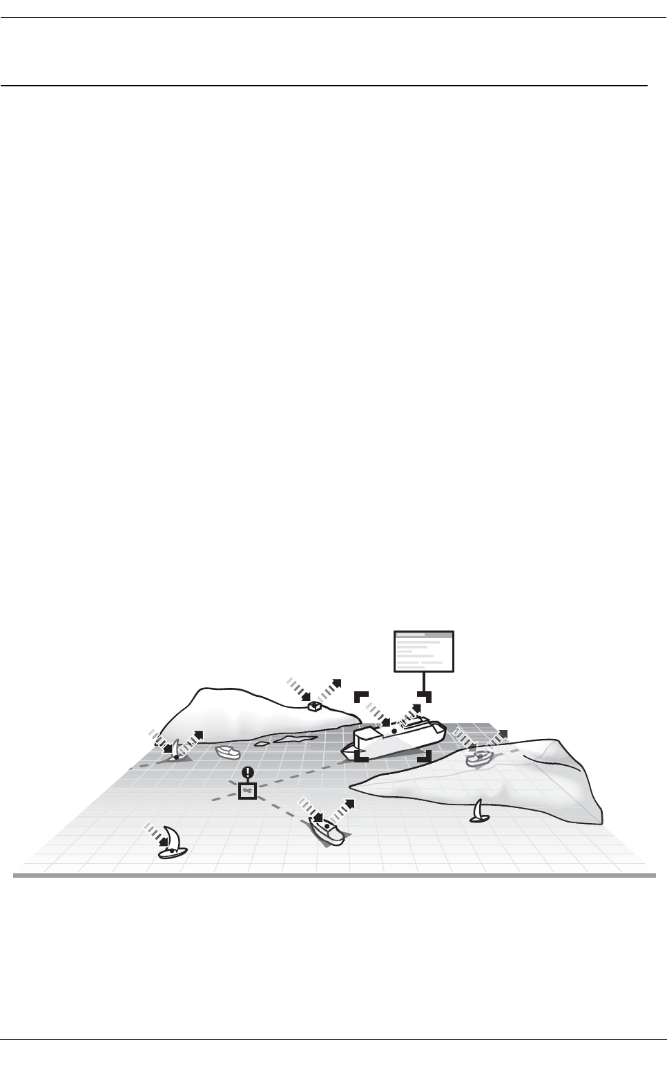
The marine Automatic Identification System (AIS) is a location and vessel information reporting system. It
allows vessels equipped with AIS to automatically and dynamically share and regularly update their position,
speed, course and other information such as vessel identity with similarly equipped vessels. Position is derived
from GPS and communication between vessels is by Very High Frequency (VHF) digital transmissions.
There are a number of types of AIS device as follows:
●Class A transceivers. These are designed to be fitted to commercial vessels such as cargo ships
and large passenger vessels. Class A transceivers transmit at a higher VHF signal power than Class
B transceivers and therefore can be received by more distant vessels, they also transmit more
frequently. Class A transceivers are mandatory on all vessels over 300 gross tonnes on international
voyages and certain types of passenger vessels under the SOLAS mandate.
●Inland AIS stations. Similar to Class A transceivers with additional features for use on Inland
waterways.
●Class B transceivers. Similar to Class A transceivers in many ways, but are normally lower cost due
to the less stringent performance requirements. Class B transceivers transmit at a lower power and at
a lower reporting rate than Class A transceivers.
●AIS base stations. AIS base stations are used by Vessel Traffic Systems to monitor and control the
transmissions of AIS transceivers.
●Aids to Navigation (AtoN) transceivers. AtoNs are transceivers mounted on buoys or other
hazards to shipping which transmit details of their location to the surrounding vessels.
●AIS Coast Station transceivers. Coast Station transceivers are a type of AIS AtoN designed to be
installed on land and used primarily as receiving stations for monitoring AIS traffic. Coast Stations
share many of the features of AIS AtoNs.
●AIS receivers. AIS receivers receive transmissions from Class A transceivers, Class B transceivers,
AtoNs and AIS base stations but do not transmit any information about the vessel on which they are
installed.
This product is an AIS Coast Station transceiver.
Figure 1 The AIS network
Introduction
Page 8
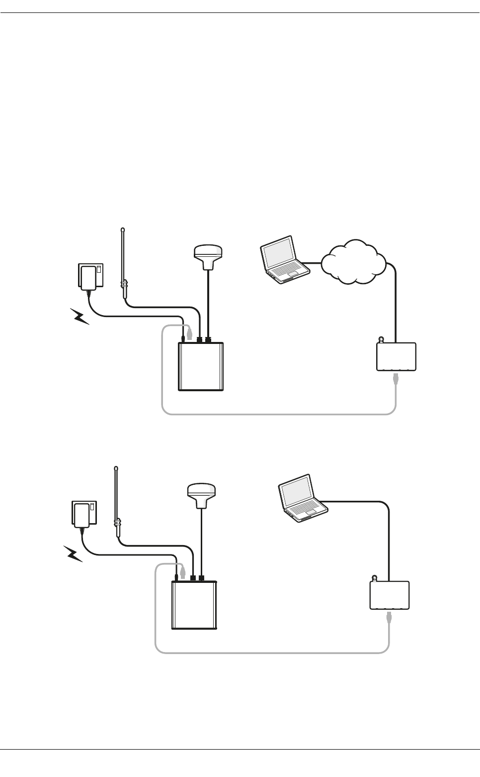
3.2 Typical Coast Station system installation
A typical application for the Coast Station is relaying AIS messages received at the coast to viewing and
database applications via the Internet. The Coast Station is connected to a VHF antenna for AIS reception
and provided with an Ethernet connection to an Internet access point.
The Coast Station is configured to stream the received AIS data to a pre-configured network destination
specified with an IP address and port number. The Coast Station can support both TCP and UDP operation,
and can operate either as a server or a client. Typically the Coast Station is configured as a TCP client
configured to push data to the public IP address of a central database server.
Alternatively the Coast Station can be connected directly to a PC via USB. Note that the tag block feature
described in section 6 is not supported over the USB connection. Figure 2, Figure 3 and Figure 4 show possible
connection schemes.
Figure 2 Coast Station installation for connection to a remote viewer/database via Ethernet
Figure 3 Coast Station installation for connection to a local viewer/database via Ethernet
Viewer / database
applications
WWW
Mains
power
VHF antenna
GPS antenna
AIS Coast
Station
Network
router
Ethernet cable
VHF antenna
GPS antenna
AIS Coast
Station
Network
router
Ethernet cable
PC
Mains
power
Introduction
Page 9
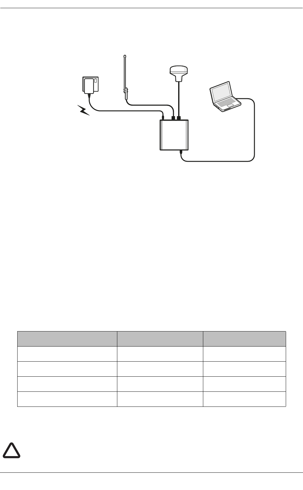
Figure 4 Coast Station installation for connection to a local viewer/database via USB
3.3 Coast Station modes of operation
The Coast Station can operate as either an AIS receiver or an AIS AtoN. The Coast Station will operate as an
AIS receiver by default and will receive and process all received AIS messages. When the Coast Station is
configured as an AIS AtoN it can not only receive AIS messages, but also transmit AIS AtoN messages. Please
refer to section 7 for further details of how to configure the Coast Station as an AIS AtoN.
3.4 Internal data logging
The Coast Station includes internal data logging capability for received AIS messages with up to 32GB
capacity. Internal data logging will continue if network connectivity to the Coast Station is lost. Logged data can
be uploaded from the Coast Station on request when network connectivity is restored. See section 6 for details
of commands used to query and upload logged data. Note that upload of logged data requires that the Coast
Station is configured for TCP connection (as described in section 5.3).
Utilisation of the internal storage capacity will depend on the level of AIS traffic in the area where the Coast
Station is deployed. A rough estimate of the log capacity can be determined from the number of AIS messages
received per minute:
For reference a single receiver station in Singapore harbour generates approximately 8MB of data per hour or
192MB per day, giving an expected log capacity of approximately 166 days.
AIS messages received/minute approximate daily log size approximate log capacity
100 messages/minute ≈11MB/day ≈2900 days
1000 messages/minute ≈11MB/day ≈285 days
2000 messages/minute ≈11MB/day ≈142 days
4000 messages/minute ≈11MB/day ≈71 days
USB cable
VHF antenna
GPS antenna
AIS Coast
Station
Mains
power
PC
The data log operates on a 'rolling' basis. Once internal data log storage is full the oldest
logged data will be erased to allow storage of new data.
!
Connections and status indicators
Page 10
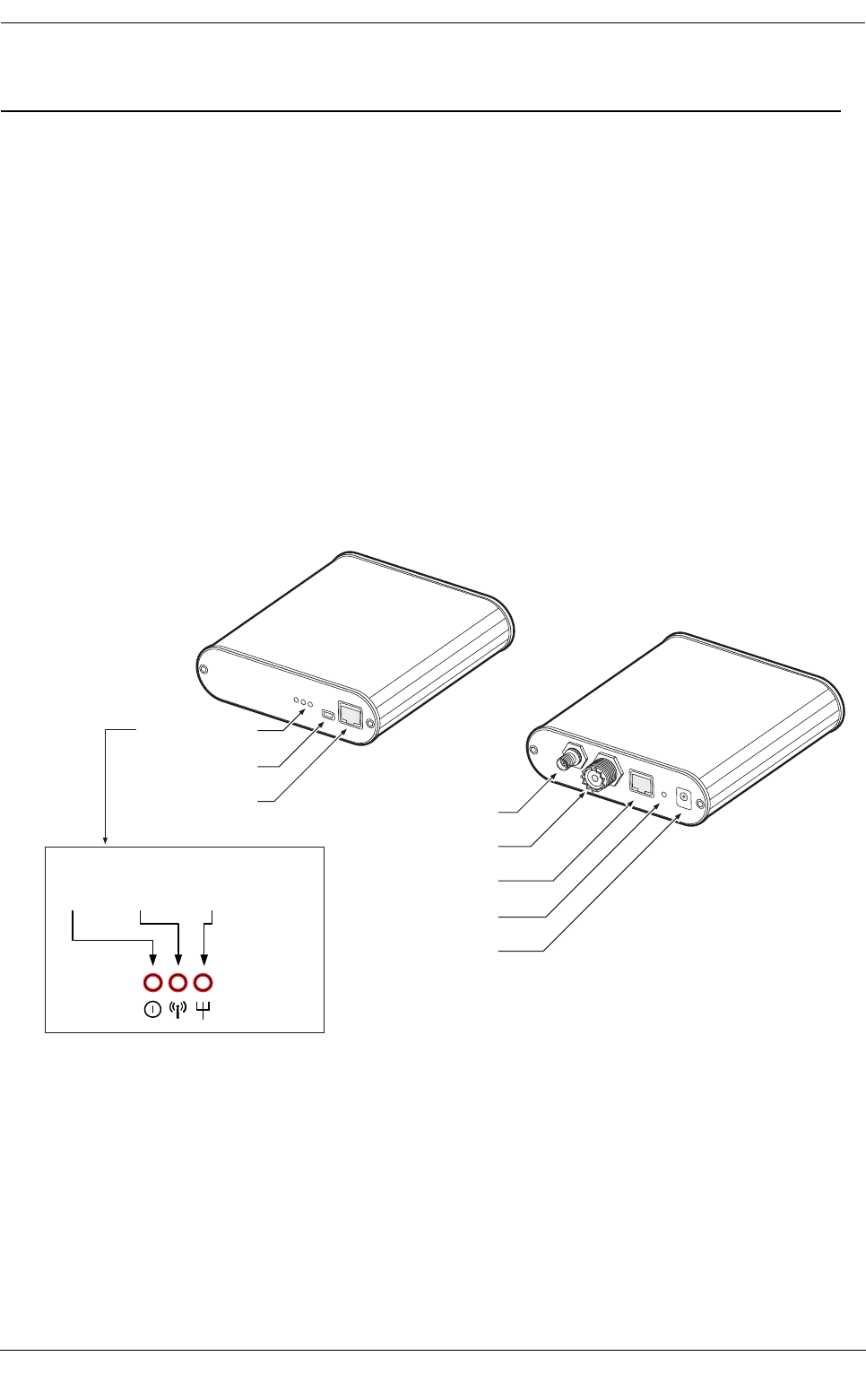
4 Connections and status indicators
The Coast Station has a number of connections and status indicators as follows and shown in Figure 5 and
Figure 5:
●VHF antenna connector for connection to a VHF antenna (not supplied). AIS messages are received
and transmitted via the VHF antenna
●GPS antenna connector for connection to the supplied GPS antenna. The Coast Station requires a
GPS position fix in order to transmit any AIS messages and to provide a time reference for data
logging.
●Ethernet connector for connection to a Local Area Network (LAN) using the supplied Ethernet cable.
●Power connector for connection to a mains power source using the supplied mains adaptor.
●Reset button used to manually reset the Coast Station to its default settings if required.
●USB connector for direct connection to a PC for configuration of the transceiver using proAtoN or
direct monitoring of AIS traffic.
●Ethernet configuration port for direct connection to a PC for configuration of network settings.
Status indicators showing the status and activity of the Coast Station including power status, AIS reception and
network activity.
Figure 5 Coast Station connections
Status indicators
USB port
Ethernet port
(for conguration) GPS antenna connector
VHF antenna connector
Ethernet port (internet)
Reset button
Power connector
Power
AIS
reception
Network
activity
Installation and configuration
Page 11
5 Installation and configuration
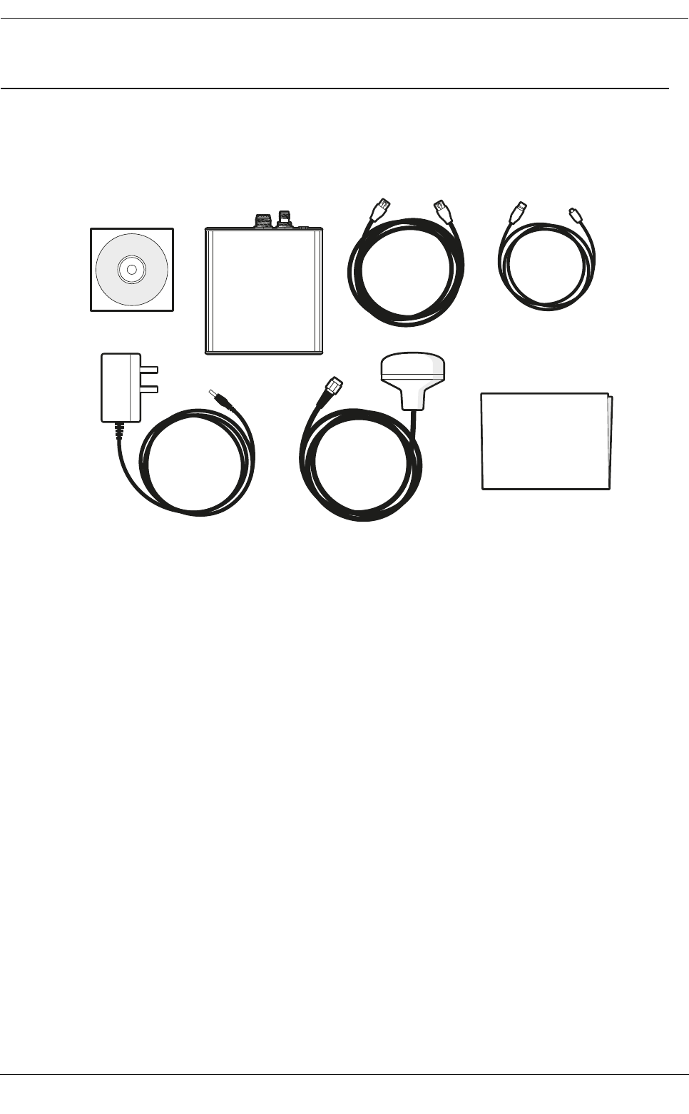
5.1 What’s in the box
Figure 6 shows the items included with the Coast Station transceiver. The following section gives a brief
overview of each item. Please ensure all items are present and if any are missing please contact your supplier.
Figure 6 What’s in the box - typical configuration
●The Coast Station transceiver.
●An Ethernet cable for connection to an Internet access point (router) and for network configuration.
●A mains power supply with interchangeable plug heads for international use.
●A CD containing product documentation and configuration software.
●A GPS Antenna with 10m cable.
●A USB cable for connection to a PC for AIS configuration using proAtoN.
●A quick-start guide providing simple instructions of how to complete basic product set-up.
Product CD
AIS Coast
Station
GPS
antenna
Ethernet
cable
Mains
adaptor
Quick-Start
Guide
USB conguration cable

Installation and configuration
Page 12
5.2 Preparing for installation
No special tools or equipment are required for installation.
5.2.1 Coast Station location
The Coast Station is designed for installation in a protected environment, i.e. indoors or inside a fully
weather-proof enclosure. The Coast Station must not be installed in a location where it may be exposed to rain
or spray.
5.2.2 VHF antenna and cable
The VHF antenna should have the following specification:
●Centre frequency 159MHz
●VSWR < 2.0
●Impedance 50 Ohms
●Power handling 12.5 Watts
●Gain 3dBi or 6dBi
It is recommended that high quality RG213 or RG214 co-axial cable is used to connect the VHF antenna to the
transceiver. The antenna cable should be as short as possible and no more than 30 metres (100 feet) in length.
When selecting the installation location for the VHF antenna:
●Install the antenna as high as possible.
●Keep the antenna away from any large vertical metallic structures.
Install the antenna with at least 1 metre horizontal separation from any other VHF antenna mounted at the
same level.
5.2.3 GPS antenna and cable
The supplied GPS antenna should be used and located externally with a clear view of the sky. Installation of
the GPS antenna is required to enable the data logging feature of the Coast Station.
5.2.4 Power supply
The Coast Station should be connected to a mains supply using the supplied mains adaptor with the
appropriate international plug type attached.
The performance and reliability of the VHF antenna is essential to correct operation of the
transceiver. Ensure that a high quality antenna suitable for use in the appropriate
environmental conditions is selected. Ensure all co-axial connections are well made and
watertight.
!
The VHF antenna should be installed according to the manufacturer's instructions.
!
The VHF antenna must be installed with at least 1 metre horizontal separation from any other
VHF antenna mounted at the same level.
!
If at any time during installation or use of the Coast Station there is a requirement to perform
a ‘power reset’ it is important that both the power supply adaptor and the USB connector are
removed from the Coast Station as the USB connection can provide power to some parts of
the Coast Station. When re-applying power the power adaptor should be connected first
followed by the USB connector if required.
!
Installation and configuration
Page 13
5.3 Network configuration
The Coast Station must be configured with various network settings so that received AIS data can be correctly
routed to the required destination. The Coast Station is configured through a web browser in a similar way to
routers and other network devices.
Configuration can be carried out either before or after installation, however it is recommended the Coast Station
is configured and tested before deployment in a remote location to ensure the network settings are correct.
During network configuration the PC used to configure the Coast Station must be disconnected from other
networks. The PC used to configure the Coast Station should be set to automatically assign IP addresses.
5.3.1 Configuration connections
●Connect the supplied mains power adapter to the Coast station and switch on the power. The power
indicator will illuminate.
●Connect the supplied Ethernet cable between the front panel Ethernet connector (marked 'CONFIG')
and a PC or laptop. Other network connections to the PC or laptop must be disabled at this point.
5.3.2 Accessing the Coast Station configuration interface
●Open a web browser on the PC or laptop and enter the default IP address (192.168.16.254) for the
Coast Station in the address bar.
●When prompted for a username and password enter “admin” for both. The configuration username
and password can be changed during configuration if required using the options in the ‘Management
menu’.
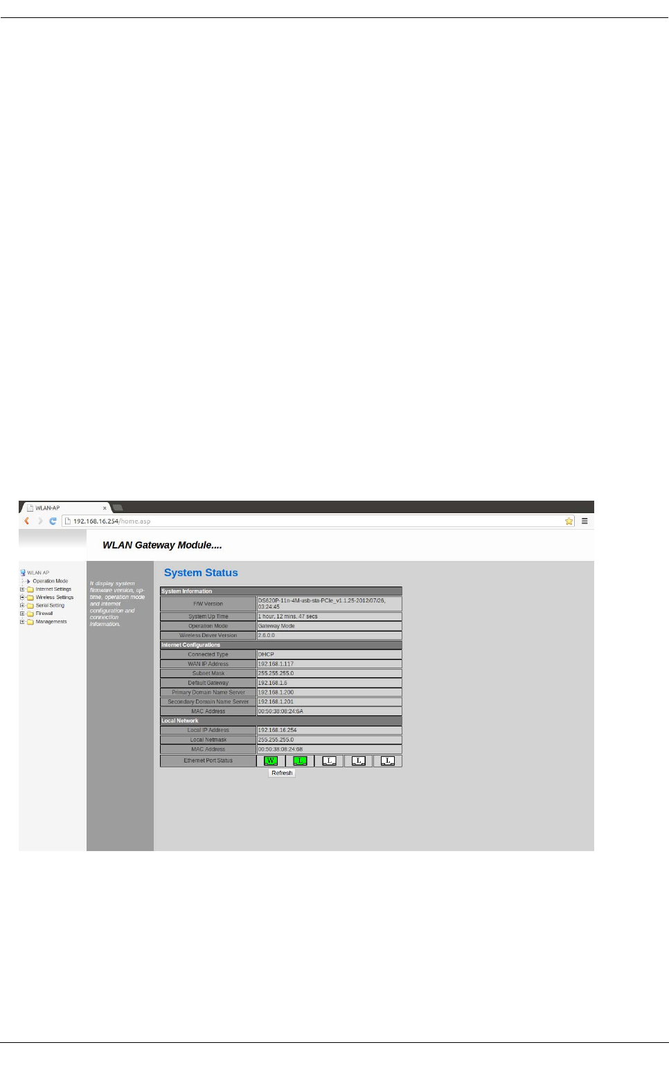
●Access to the configuration interface is now available in the web browser. The initial menu and status
screen will be as shown in Figure 7.
Figure 7 Coast Station network configuration home screen
5.3.3 Configuring the operating mode
The following steps will configure the Coast Station to forward all received AIS data to a remote server. The
server must have a static IP address and the port number for AIS data delivery must be known.
After configuration the Coast Station will automatically attempt to connect to this IP address. If the connection
is lost due to network issues the Coast Station will attempt automatic reconnection.
The basic operating mode of the Coast Station network interface must first be configured:

Installation and configuration
Page 14
●From the menu bar at the left of the configuration screen select the ‘Operation Mode’ menu.
●Select the ‘Gateway’ option
●Click the ‘Save’ button at the bottom of the screen
●Wait whilst the configuration is applied.
●It may be necessary to refresh the web page after the configuration countdown has completed.
5.3.4 Configuring internet settings
The Coast Station must be configured for Internet (WAN) connection; specifically it must be configured to
obtain an IP address:
●Either automatically via DHCP, or
●Manually by assigning a static IP address
Note: This does not affect the internal IP address of the Coast Station used for accessing the configuration
menu via the ‘CONFIG’ Ethernet connector on the front panel.
The configuration steps are as follows:
●From the menu bar at the left of the configuration screen select the ‘Internet settings’ menu.
●Select the ‘WAN’ option
●For most installations the ‘DHCP (Auto config)’ option should already be selected and no changes are
required.
●If the Coast Station is to be configured with a static IP address select this option from the drop down at
the top of the screen and complete the required address fields.
5.3.5 Configuring serial port settings
The Coast station must be configured to forward AIS data using the correct protocol and server address
settings. The configuration values will depend on the configuration of the remote server the Coast Station is
sending data to.
●From the menu bar at the left of the configuration screen select the ‘Serial Setting’ menu.
●Select the ‘Serial port #1’ option.
●Configure the ‘Main connection configuration’ settings as follows:
○Select either a UDP or TCP connection, as appropriate to the remote connection configuration. A
TCP connection is reccomended as this provides a bi-directional connection which can be used
for remote configuration and control of the Coast Station. Select the operating mode as either
server or client. Typically Client mode should be selected. In this mode the Coast Station will
attempt to connect to a remote server (i.e., it is initiating the connection). Server mode is only
appropriate when the Coast Station is accessible with a public IP address and suitable NAT
configuration at the Internet access point.
○Enter the IP address for the remote server. This should be a public IP address accessible on the
Internet.
○Enter the server port number the Coast Station should connect to. The port number is usually
defined by the server application that will be receiving data from the Coast Station.The ‘Reconnect
interval’ should be left at the default 10 seconds.
○The ‘Connection’ option should be set to ‘System Bootup’
○The serial port baud rate should be changed to 115200 baud, other settings are correct as default,
8 data bits, no parity, 1 stop bit and no flow control.
●Click the ‘Save’ button at the very bottom of the screen.

Installation and configuration
Page 15
5.3.6 Testing the configuration
Configuration of the Coast Station is now complete. To test the configuration, connect the Ethernet port on the
rear of the Coast Station (marked ‘ETHERNET’) to an access point or Router with access to the public
internet. The Coast Station will acquire an IP address via DHCP and commence streaming received AIS data
to the configured server address.
The Coast Station must be able to receive AIS targets to test the connection, so connection of a VHF antenna
and presence of AIS targets is also required. If the configuration is correct the AIS activity LED on the Coast
Station will flash to indicate target reception, and the Ethernet activity LED will flash to indicate network
activity. You should now confirm that AIS data is being received at the remote server.
5.4 Resetting the Coast Station
An incorrect or incomplete configuration may result in the Coast Station configuration web page being
unavailable. The Coast Station network interface can be reset to factory configuration using the recessed reset
button on the rear panel (see Figure 5).
To reset the Coast Station apply power, then press and hold the reset button for at least 10 seconds. After
reset the Coast Station configuration interface will be available as described in section 5.3.

Coast Station data communication protocol
Page 16
6 Coast Station data communication protocol
The Coast Station generates NMEA0183 sentences with a standard format TAG block for transport over a
TCP/IP connection. The tag block includes three parameters as defined in the table below. Further information
on NMEA0183 TAG blocks can be found in the latest NMEA0813 standard document.
An example sentence including TAG block is provided below:
\s:COAST STATION 1,c:1409580181,t:LIVE*60\!AIVDM,1,1,,B,13:PSCgP00wle`bMEsOf4?wp2D00,0*3E
This shows a live data sentence from the Coast Station 'Coast Station 1' received at UNIX time 1409580181
(Mon, 01 September 2014 14:03:01 GMT).
\s:COAST STATION 1,c:1409581305,t:LOGGED*7B\!AIVDM,1,1,,A,3;VjmcOP4hOle`2MEs7hKwwp00T1,0*31
The second examples shows upload of logged data from Mon, 01 September 2014 14:21:45 GMT.
6.1 Setting the Coast Station name
The Coast Station can operate as an AIS receiver or as a AIS AtoN. When the Coast Station is operated as an
AIS AtoN the name is set during configuration as defined in section 7.4. However, when the Coast Station is
used as an AIS receiver it is not possible to set the Coast Station name via the ‘Real AtoN’ tab in proAtoN as
this will only be successful if an MMSI is also programmed into the Coast Station and MMSIs are not required
for receive only AIS devices.
Note that it is not essential to set the Coast Station name. Omitting to set the Coast Station name will mean the
‘source identification’ field in the tag block will be empty. All other functionality is unaffected.
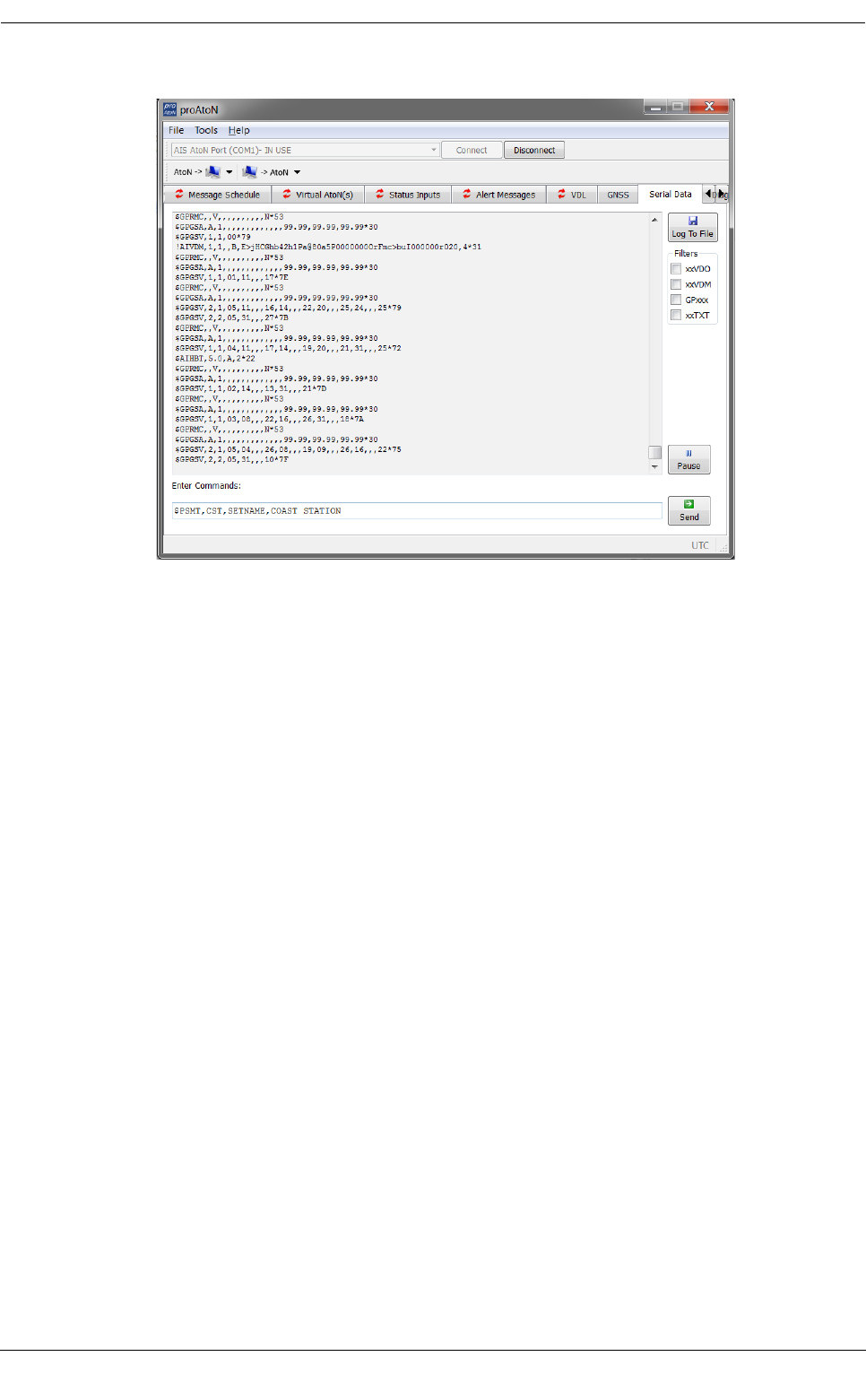
To configure the Coast Station name in AIS receiver mode:
1. Install and launch proAtoN as described in section 7.1.
2. Connect the Coast Station to a PC as described in 7.2.
3. Connect proAtoN to the Coast Station as described in 7.3.
4. Go to the serial tab in proAtoN and enter the command $PSMT,CST,SETNAME, <name> as shown
below where the name chosen is ‘COAST STATION’, then click ‘Send’.
TAG block parameter Contents
s (Source identification) The name of the Coast Station, taken from the first 15 characters of
the Coast Station name (see section 6.1)
c (UNIX time)
The Unix time stamp (seconds since 1/1/1970) for reception of the
proceeding AIS message.
For Live data this is the current time, for logged data this is the time
the logged data was captured.
t (Text string)
Text describing the proceeding data as either live or logged. The text
is either 'LIVE' or 'LOGGED'.
When uploaded logged data from the Coast Station this parameter
is used to differentiate live and logged data in the output data
stream.
Coast Station data communication protocol
Page 17
Figure 8 Configuration of Coast Station name in AIS receiver mode
6.2 Heartbeat output
The Coast Station outputs a regular heartbeat sentence. This sentence allows the status of connectivity to the
Coast Station to be monitored. The heartbeat sentence takes the format:
\s:COAST STATION 1,c:1409649473,t:LIVE*6E\$AIHBT,5.0,A,3*23
Where:
$AIHBT,configured_repeat_interval,equipment_status,sequential_sentence_identifier*23
The configured repeat interval is 5.0 seconds. The equipment status will always return 'A' indicating normal
operation.
6.3 Coast Station control sentences
The following proprietary NMEA sentences are used to control the internal data logging process. Commands
may be sent via the network connection from a remote server application. It is also possible to configure the
AIS AtoN element of the Coast Station using NMEA0183 sentences defined for AIS AtoN configuration. Please
contact SRT Marine System Solutions technical support (support@srt-marinesystems.com) for further
information and advice on remote network configuration of the Coast Station AtoN parameters.
6.3.1 Query the internal data log
$PSMT,CST,QUERY*14
Query the Coast Station for the duration covered by the internal data log. The Coast Station returns the date
and time stamps for the oldest and most recent data in the internal log. An example response is:
\s:COAST STATION 1,c:1409583076,t:LIVE*6A\$PSMT,CST,01-09-2014 14:51:15,01-09-2014 14:20:42,ACK*13
This indicates the internal data log runs from 14:20:42 on 1st September 2014 to 14:51:15 on the same day.
All times are UTC. The 'ACK' at the end of the response indicates that logged data is available. A 'NACK' is
returned in this field if no logged data is available.

Coast Station data communication protocol
Page 18
6.3.2 Query the remaining storage capacity
$PSMT,CST,FSSPACE*0F
Query the Coast Station for the remaining internal data log storage space. The available space is returned as
follows:
$PSMT,CST,FSSPACE,freespace,ACK*4B
Where freespace is the available space in KB. For example the following response would indicate 31154528KB
(or 29.711GB) capacity remaining.
\s:COAST STATION 1,c:1409583294,t:LIVE*64\$PSMT,CST,FSSPACE,31154528,ACK*4B
6.3.3 Upload data
To upload data from the Coast Station internal data log the start and end time for the log must be provided. The
command sentence format is as follows:
$PSMT,CST,UPLOAD,startdate,starttime,stopdate,stoptime*hh
For example:
$PSMT,CST,UPLOAD,010914,142500,010914,143500*5C
This example requests data upload from 14:25:00 to 14:35:00 on the 1st September 2014.
This command requests upload of all data between the start time and date and the stop time and date. It is
recommended that the time window for upload is minimised to reduce upload duration.
The checksum (*hh) must be calculated according to the final command contents before the command is sent
to the Coast Station. Tools to calculate checksums for NMEA sentences can be found on-line or alternatively
please contact SRT Marine System Solutions for assistance.
If the requested data is available the Coast Station will responds with an acknowledgement sentence. An 'ACK'
in the last field of the response indicates the requested data is available and upload will commence.
\s:COAST STATION 1,c:1409583744,t:LIVE*6C\$PSMT,CST,UPLOAD,010914,142500,010914,143500,ACK*39
If the requested data is not available the Coast Station will respond with a negative acknowledgement (NACK)
sentence:
\s:COAST STATION 1,c:1409584932,t:LIVE*64\$PSMT,CST,UPLOAD,010913,142500,010913,143500,NACK*77
6.3.4 Stop data upload
$PSMT,CST,STOPUPLOAD*45
Upload of requested data will continue until all data between the start and stop time stamps is uploaded. This
command may be sent at any time to stop the upload. The acknowledgement response is of the format:
\s:COAST STATION 1,c:1409649374,t:LIVE*6E\$PSMT,CST,STOPUPLOAD,ACK*20
6.3.5 Stop data logging process
$PSMT,CST,STOPLOGGING*05
This command will stop the data logging process. Note that data logging will be automatically restarted if power
to the Coast Station is cycled. This command should be used prior to clearing the internal data log using the
clear command below. The acknowledgement response is of the format:
\s:COAST STATION 1,c:1409649423,t:LIVE*6B\$PSMT,CST,STOPLOGGING,ACK*60
6.3.6 Clear internal data log
$PSMT,CST,CLEARLOGS*10

Coast Station data communication protocol
Page 19
This command will clear (erase) all logged data. This is irreversible. Data logging should be stopped using the
stop command documented above prior to clearing the log. Once the log has been cleared logging may be
restarted either by power cycling the Coast Station, or using the start logging command provided below. The
acknowledgement response is of the format:
\s:COAST STATION 1,c:1409653081,t:LIVE*6C\$PSMT,CST,CLEARLOGS,ACK*75
6.3.7 Start data logging process
$PSMT,CST,STARTLOGGING*5D
This command re-starts the internal data logging process. Note that data logging will be automatically restarted
if power to the Coast Station is cycled. The acknowledgement response is of the format:
\s:COAST STATION 1,c:1409649461,t:LIVE*6D\$PSMT,CST,STARTLOGGING,ACK*38

Configuration using proAtoN
Page 20
7 Configuration using proAtoN
The proAtoN PC application is supplied on the CD packaged with the transceiver. The application provides
features for configuration of the transceiver and confirming correct operation before deployment.
The main features of the application are:
●Configuration of essential transceiver parameters such as MMSI, name and dimensions
●Configuration of reporting schedules
●Configuration of virtual and/or synthetic AtoN reporting schedules
●Configuration of other messaging features
●GPS diagnostics
●System diagnostics and alarm display
7.1 proAtoN Installation
proAtoN should be installed from the CD supplied with the transceiver. The steps to complete the installation
are as follows:
1. Insert the CD into your PC
2. Navigate to the proAtoN folder on the CD
3. Double click the ‘setup.exe’ item to start the installation process
4. Follow on screen instructions to complete the installation
Following successful installation the application can be launched from the proAtoN folder in the Windows start
menu. USB device drivers for the transceiver are installed automatically during installation of proAtoN.
7.2 Connection of the Coast Station to a PC
The Coast Station should be connected to a PC via its USB connector using the supplied USB cable.
If the Coast Station is intended only as a receiving station there is no requirement to complete
any of the configuration described in this section. The majority of configuration options
described in this section relate to the use of the Coast Station as a shore based AIS AtoN
Transceiver in conjunction with networked receive capability.
!
Configuration using proAtoN
Page 21
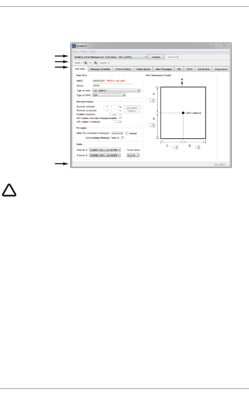
7.3 Application layout
The basic layout of the proAtoN application is provided in Figure 9.
Figure 9 proAtoN application layout
COM Port selection
When connected via USB the COM port associated with the transceiver will be listed in the selection drop down.
To connect to the transceiver select the ‘AIS AtoN Port’ option from the drop down and click the ‘Connect’
button.
Read / Write configuration
Clicking the left hand button will transfer current configuration information from the transceiver to proAtoN.
Clicking the right hand button will configure the transceiver with the information currently displayed in proAtoN.
It is possible to select transfer of configuration information relating only to the currently selected tab, or to all
tabs by clicking the drop down arrow to the right of each button. The default operation for each button is to read
or write data relating to the selected tab only. It is highly recommended that prior to deploying the AtoN the
“Send all Configuration” option is used on the write button.
Configuration tabs
The configuration and status of the transceiver is displayed through a number of tabs.
●Real AtoN tab: Configuration of AtoN MMSI, name, type, dimensions, position and radio parameters.
●Message schedule tab: Configuration of FATDMA or RATDMA message schedules.
●Virtual AtoN tab: Configuration of virtual and/or synthetic AtoN transmissions.
●Status input tab: Not relevant for Coast Station.
●Alert messages tab: Not relevant for Coast Station.
●VDL: Not relevant for Coast Station.
●GNSS: Displays signal strength and status information for the transceiver GPS receiver.
●Serial data: Displays raw IEC61162 (NMEA0183) data output from the transceiver and provides a
means of sending control commands to the Coast Station.
COM Port selection
Read / Write conguration
Conguration tabs
Status bar
Note that the Status Inputs, Alert Messages and VDL tabs are not relevant to the Coast Station
product and should not be configured.
!

Configuration using proAtoN
Page 22
●Diagnostics: Displays software version information, alarms and other key status information.
When connected to a transceiver a synchronisation status icon is displayed alongside the title of each tab. This
icon indicates the current synchronisation status of the information displayed in that tab with the internal
configuration of the transceiver. The synchronisation status icons are shown in Figure 10.
Figure 10 proAtoN tab synchronisation icons
Synchronisation is achieved by either writing the configuration displayed in proAtoN to the transceiver (click the
write configuration button), or reading the current configuration from the transceiver for display in proAtoN (click
the read configuration button).
Status bar
The status bar displays the current connection status of the application (bottom left) and the current GPS time
(if available, bottom right).
7.4 Transceiver configuration
The following sections describe the configuration options available and their effect on the behavior of the
transceiver. Configuration of an AIS AtoN transceiver requires knowledge of the local AIS environment and
may require interaction with shore infrastructure. Familiarity with the current IALA guidelines on the use of AIS
Aids to Navigation (IALA A-126) is assumed.
7.4.1 Configuration of ‘Real’ AtoN parameters
The following parameters associated with the ‘real’ AIS AtoN transceiver should be configured via the ‘Real
AtoN’ tab:
●MMSI
The MMSI number associated with the ‘real’ AtoN. Typically the MMSI number for a ‘real’ AtoN station
follows the format 99MID1XXX where MID is the appropriate national MID and XXX is a number
unique to this station.
●Name
The name of the AtoN station as broadcast to other AIS users. Up to 34 characters are available for
the name.
●Type of AtoN
Select from a list of possible types of AtoN. The types are as defined by IALA in IALA A-126.
●Type of EPFS
Select the type of EPFS (Electronic Position Fixing System) used by the transceiver. Note this
selection does not affect the hardware configuration, only the contents of the ‘Type of EPFS’ field in
transmitted AtoN position reports. The transceiver is equipped with a GPS module by default.
Alternatively for a fixed or shore based transceiver a surveyed position type can be selected. Note
that when the surveyed position is selected the surveyed position is broadcast to other AIS users and
GPS position information is ignored.
●Nominal position
Green - Tab synchronised
Red - Tab not synchronised
Blue - Synchronisation in progress
Tab edited (sync required)

Configuration using proAtoN
Page 23
Enter the nominal or charted position of the AtoN. This is the position transmitted to other AIS users
for a fixed AtoN when the ‘Surveyed’ EPFS type is selected. For all other configurations this position
is used to perform ‘off position’ calculations only; the actual GPS position is broadcast to other users.
○The application can average the current GPS position over 5 minutes and use this value for the
nominal position. Click the ‘Get GPS position’ button to the right of the latitude and longitude fields
to begin this process. N.B. The GPS location should only be captured at the installation
location.
○The position accuracy can only be entered when the type of EPFS is set to ‘Surveyed’. The
accuracy should be set in accordance with the accuracy of the surveyed position.
●Off position alternate message enable
The current GPS position is compared to the nominal position according to the algorithm defined in
IALA A-126 Annex A, Example 1. The off position threshold distance is specified in metres. If the
transceiver determines that it is ‘off position’ then the alternate reporting schedule for message #21
(index 2) is enabled. For example, the alternate reporting schedule could be configured to decrease
the reporting interval if the AtoN has drifted off position. The off position flag in message #21 is set
when off position regardless of this setting.
The transceiver off position algorithm is always operational and compares the current GPS position to
the nominal position of the transceiver.
●MMSI for addressed messages
This is the destination MMSI used for all addressed message types generated by the transceiver. This
is usually the MMSI of a shore station collecting status information from the transceiver. It is also
possible to enable the acknowledgement of received binary messages (via message #7 or #13).
●Dimensions
The dimensions of the AtoN should be entered to the nearest metre. Guidance on the appropriate
configuration of dimensions for various types of AtoN can be found in IALA A-126.
●Radio channels
Selection of alternative radio channels for AIS transmission and reception is possible, however in
most cases the default channels (AIS1 and AIS2) should be used.
●Transmitter power level
The transmitter power level for the transceiver can be selected as 1W, 2W, 5W or 12.5W. The default
value of 12.5W is appropriate for most scenarios.
Configuration using proAtoN
Page 24
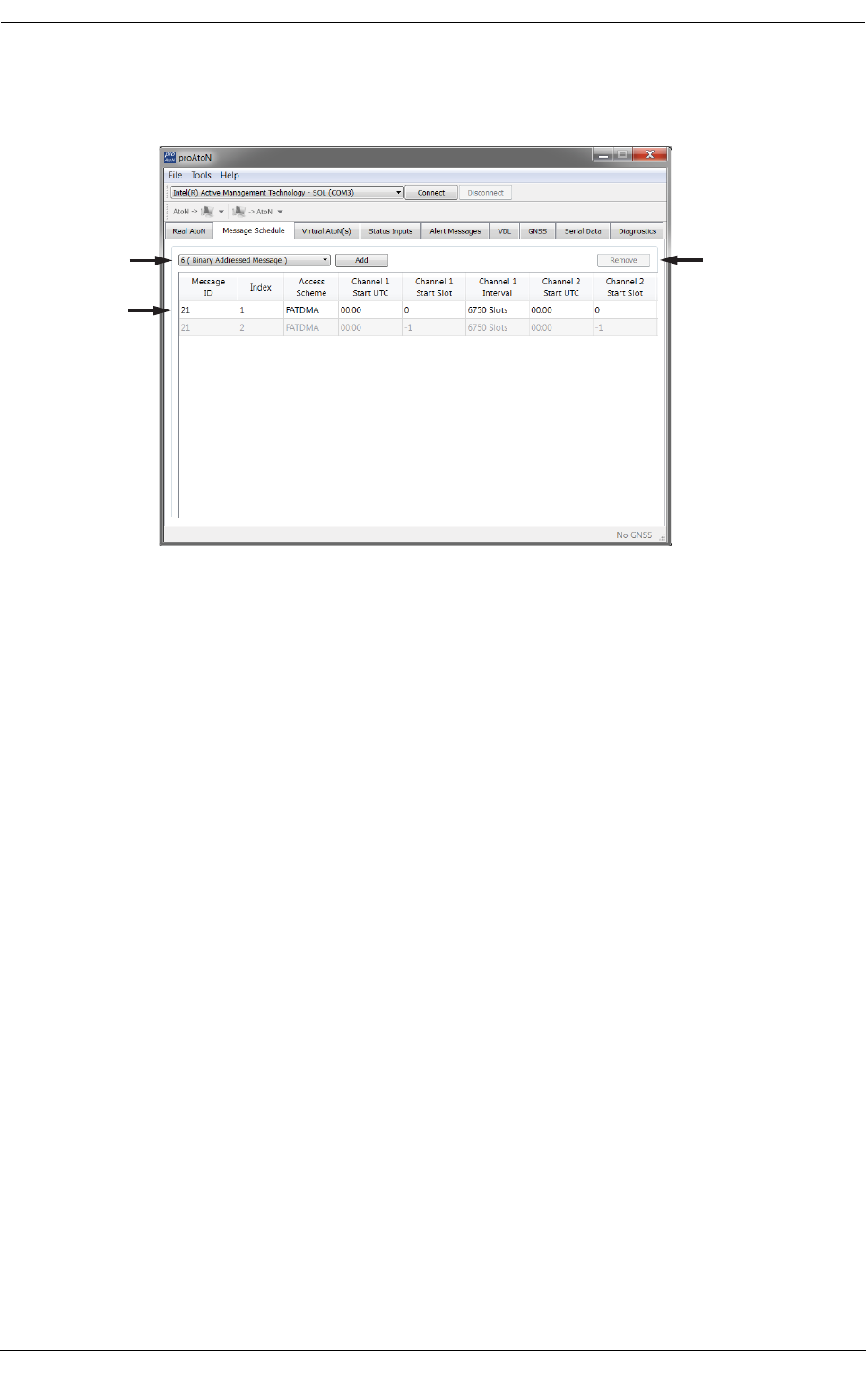
7.4.2 Message schedule configuration
The layout of the message schedule tab is described in Figure 11.
Figure 11 proAtoN message schedule tab layout
Default messages
An AIS AtoN position report is made using AIS message #21. This message occupies two AIS slots. The
default configuration shown in proAtoN includes two message #21 schedule configurations. The first
configuration, index 1, is the primary position reporting schedule for the transceiver. The second, index 2, is
the alternate position reporting schedule selected when the ‘off position’ monitor is enabled and the AtoN is
determined to be off position (see section 7.4.1). If the alternate ‘off position’ schedule is not required it can be
deactivated by selecting the associated row in the message schedule table and clicking the ‘Deactivate’ button.
When deactivated the alternate schedule will be greyed out.
Access scheme selection
The access scheme for each message must be selected as either FATDMA or RATDMA (see section 3.2). The
selection is made by selecting the required row in the schedule table, then clicking on the current access
scheme in that row. A drop down menu will then appear in that location allowing selection of the required
access scheme.
●FATDMA
Configuration of an FATDMA schedule continues in section 7.4.3.
●RATDMA
Configuration of an RATMDA schedule continues in section 7.4.4.
7.4.3 FATDMA Schedule configuration
Using the FATDMA (Fixed Access TDMA) access scheme the actual slot for each transmission made by the
transceiver is specified. There are 2250 slots per minute (or frame) on each AIS channel. The scheduled slots
must be reserved for the transceiver by an AIS base station operating in the same area using AIS message
#20. Further information on FATDMA reservations and slot allocation schemes can be found in IALA A-124,
Appendix 14.
The parameters required for an FATDMA schedule are as follows.
Add new message
schedules
Current messages
and schedules
Deactivate or remove
selected schedule
Configuration using proAtoN
Page 25
Channel 1 start UTC
This is the hour and minute for transmission on channel 1. This specifies the AIS frame (minute) within a day
in which the start slot for channel 1 resides.
Channel 1 start slot
This is the slot number for the first transmission on channel 1. The slot number can range from -1 (transmission
disabled on this channel) to 2249. Note that each message #21 transmission occupies two slots and associated
base station slot reservations must therefore reserve two slots.
Channel 1 interval
This is the interval in slots between transmissions on channel 1. The interval can range from 0 to 3240000 slots,
which equates to an interval of one day. Typically the interval is set to 13500 slots (6 minutes) on each channel
which results in an overall interval of 3 minutes.
Channel 2 start UTC
This is the hour and minute for transmission on channel 2. This specifies the AIS frame (minute) within a day
in which the start slot for channel 2 resides. Typically the channel 2 start time is offset by 3 minutes from the
start time used for channel 1. With a 6 minute reporting interval on each channel this results in a transmission
every 3 minutes on alternating channels.
Channel 2 start slot
This is the slot number for the first transmission on channel 2. The slot number can range from -1 (transmission
disabled on this channel) to 2249. Note that each message #21 transmission occupies two slots and associated
base station slot reservations must therefore reserve two slots.
Channel 2 interval
This is the interval in slots between transmissions on channel 2. The interval can range from 0 to 3240000 slots,
which equates to an interval of one day. Typically the interval is set to 13500 slots (6 minutes) on each channel
which results in an overall interval of 3 minutes.
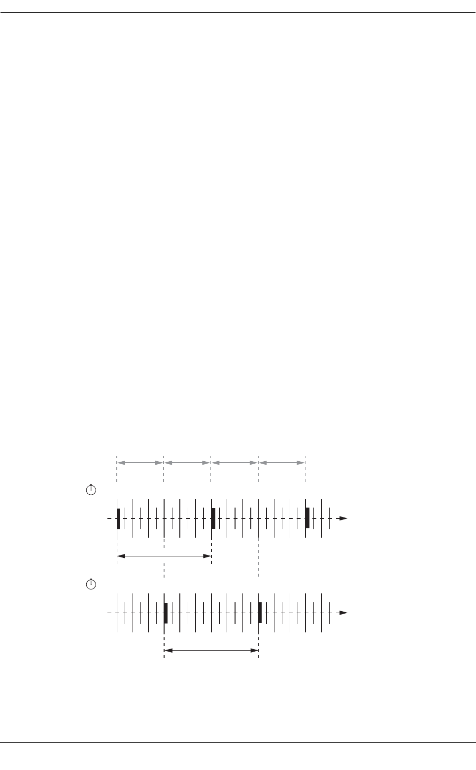
Example FATDMA schedule
A typical transmission schedule requires that the AIS AtoN transceiver transmit AIS message #21 every three
minutes on alternating channels. The transmission schedule is presented diagrammatically in Figure 12.
Figure 12 Example FATDMA schedule
Channel 1
00:01
00:02
00:03
00:04
00:05
00:06
00:07
00:08
00:09
00:10
00:11
00:12
00:00
hh:mm
Channel 1 interval
13500 slots (6 minutes)
Channel 2
00:01
00:02
00:03
00:04
00:05
00:06
00:07
00:08
00:09
00:10
00:11
00:12
00:00
hh:mm
Channel 2 interval
13500 slots (6 minutes)
Overall interval
6750 slots
(3 minutes)

Configuration using proAtoN
Page 26
This schedule can be configured using the following values:
●Channel 1 start UTC = 00:00 (the first frame of every hour)
●Channel 1 start slot = 0 (the first slot in the frame, so slots 0 and 1 are used by the message #21
transmission)
●Channel 1 interval = 13500 slots (this equates to a 6 minute interval as there are 2250 slots per
minute)
●Channel 2 start UTC = 00:03 (the third frame of every hour)
●Channel 2 start slot = 0 (the first slot in the frame, so slots 0 and 1 are used by the message #21
transmission)
●Channel 2 interval = 13500 slots (this equates to a 6 minute interval as there are 2250 slots per
minute)
The transceiver is now configured to report message #21 on channel 1 every 6th minute, and on channel 2
every 6th minute, but offset by three minutes from channel 1. This results in a transmission of message #21
every three minutes on alternating channels. The actual start slot selected for each channel will depend on the
FATDMA allocations in the area of operation.
7.4.4 RATDMA Schedule configuration
Using the RATDMA (Random Access TDMA) access scheme the time for each transmission made by the
transceiver is specified. The transceiver will determine the actual slots used for transmission based on internal
knowledge of the AIS environment gained from the AIS receivers.
The parameters required for an RATDMA schedule are as follows.
Channel 1 start UTC
This is the hour and minute of the frame in which transmission will occur on channel 1. The slot used within this
frame will be determined by the transceiver.
Channel 1 interval
This is the interval in minutes between transmissions on channel 1. A typical value is 6 minutes.
Channel 2 start UTC
This is the hour and minute of the frame in which transmission will occur on channel 2. The slot used within this
frame will be determined by the transceiver.
Channel 2 interval
This is the interval in minutes between transmissions on channel 1. A typical value is 6 minutes.
Configuration using proAtoN
Page 27
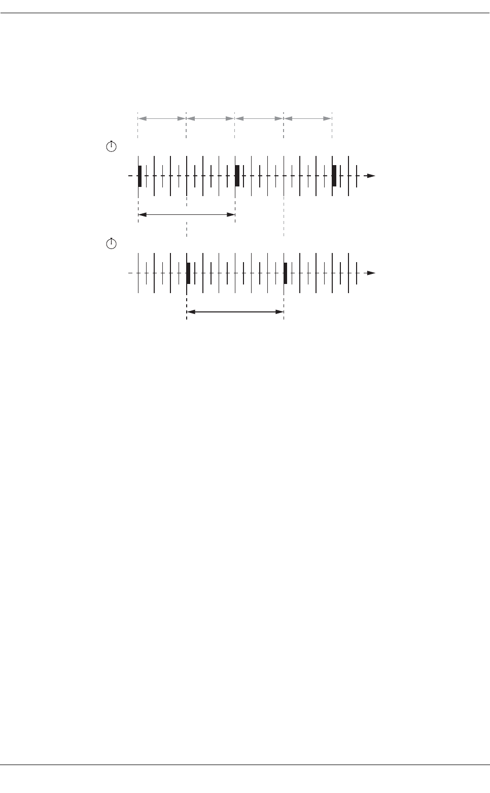
Example RATDMA schedule
A typical transmission schedule requires that the AIS AtoN transceiver transmit AIS message #21 every three
minutes on alternating channels. The transmission schedule is presented diagrammatically in Figure 13.
Figure 13 Example RATDMA schedule
This schedule can be configured using the following values:
●Channel 1 start UTC = 00:00 (the first minute of every hour)
●Channel 1 interval = 6 minutes
●Channel 2 start UTC = 00:03 (the third minute of every hour)
●Channel 2 interval = 6 minutes
The transceiver is now configured to report message #21 on channel 1 every 6th minute, and on channel 2
every 6th minute, but offset by three minutes from channel 1. This results in a transmission of message #21
every three minutes on alternating channels. The exact timings of the transmissions within the selected minute
will vary as the transceiver selects available slots using RATDMA.
Channel 1
00:01
00:02
00:03
00:04
00:05
00:06
00:07
00:08
00:09
00:10
00:11
00:12
00:00
hh:mm
Channel 1 interval
6 minutes
Channel 2
00:01
00:02
00:03
00:04
00:05
00:06
00:07
00:08
00:09
00:10
00:11
00:12
00:00
hh:mm
Channel 2 interval
6 minutes
Overall interval
(3 minutes)
Configuration using proAtoN
Page 28
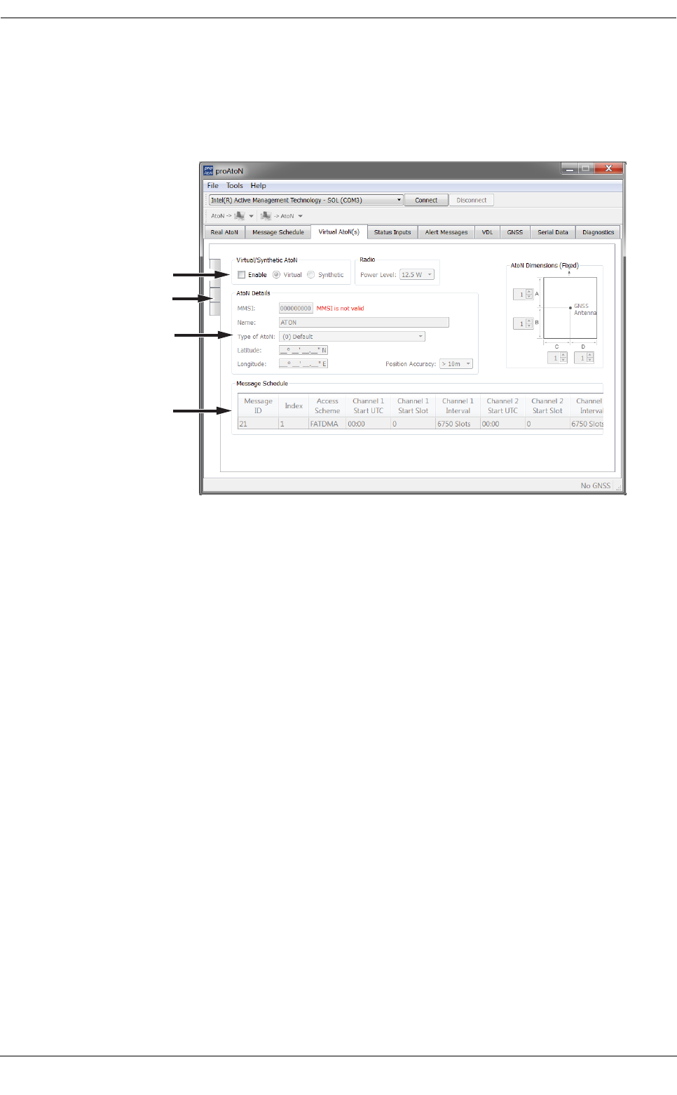
7.4.5 Virtual AtoN configuration
The transceiver can be configured to transmit position reports for up to five virtual or synthetic Aids to
Navigation. This configuration is carried out using the Virtual AtoN(s) tab in proAtoN. Within this tab there are
sub-tabs relating to each of the five virtual or synthetic AtoNs. The sub-tabs are visible at the left hand edge of
the window. The layout of the virtual AtoN configuration tab is provided in Figure 14.
Figure 14 Virtual AtoN configuration tab layout
The following parameters are required to configure a virtual or synthetic AtoN. Note that the ‘real’ AtoN must
be properly configured in order to make use of the virtual AtoN feature.
Virtual / Synthetic AtoN
Each virtual AtoN required must be separately enabled by checking the ‘Enable’ checkbox. The type of virtual
AtoN can then be selected.
●Virtual AtoN
A virtual AtoN is transmission of message #21 for an Aid to Navigation that does not physically exist.
A virtual AtoN may be used to mark a temporary hazard to navigation, e.g., a wreck. For further
information on the use of virtual AtoNs please refer to IALA A-126, IALA O-143 and IALA guideline
1081.
●Synthetic AtoN
A synthetic AtoN is transmission of message #21 from an AIS station located remotely from the
physical Aid to Navigation. An example of use is to provide an AIS AtoN target for a buoy or mark that
is not capable of supporting AIS AtoN hardware.
Virtual / Synthetic AtoN Details
The basic configuration of a virtual or synthetic AtoN is comparable to that required for a ‘real’ AIS AtoN. Note
that the MMSI number format is different:
●A virtual AtoN MMSI has the format 99MID6XXX, where MID is the appropriate national MID and XXX
is a number unique to this station.
●A synthetic AtoN MMSI has the same format as a real AtoN MMSI, e.g., 99MID1XXX, where MID is
the appropriate national MID and XXX is a number unique to this station.
The position of the virtual or synthetic AtoN must be configured appropriately to the position of the aid. Note
that a virtual AtoN has no dimensions whereas the dimensions of a synthetic AtoN should be configured.
Enable virtual AtoN
and select type
Virtual AtoN subtabs
Virtual AtoN details
Virtual AtoN schedule

Configuration using proAtoN
Page 29
Virtual AtoN schedule
The transmission schedule for a virtual or synthetic AtoN must be configured in the same way as that for the
‘real’ AtoN. The TDMA access scheme, start times and intervals must be configured in the virtual AtoN tab
following the guidance in section 7.4.3 or 7.4.4 as appropriate. When an FATDMA schedule is used it is
important to ensure the slot allocations used for the virtual and real AtoNs are different in every case. Also note
that two consecutive slots are used for each virtual AtoN report.
7.5 Transceiver diagnostics
The proAtoN application provides a number of features to assist with installation of an AIS AtoN and diagnosis
of fault conditions. These features are available through the GPS, Serial Data and Diagnostics tabs in proAtoN.
7.5.1 GPS tab
The GPS tab shows the status of the GPS receiver built into the transceiver. This provides an indication of the
quality of the GPS satellite signals being received along with the current position of the transceiver.
At least four satellites with a carrier to noise ratio in excess of 40 dBHz are required for an acceptable position
fix. Relocating the transceiver or connecting an external GPS antenna can help improve the signal quality and
resulting position accuracy.
The internal GPS receiver supports SBAS (Satellite Based Augmentation Service) to enable improved
accuracy and integrity of GPS position fixes. The availability of SBAS depends on the installation location of
the transceiver (the WAAS SBAS service covers most of the US and the EGNOS service covers Europe).
7.5.2 Serial data tab
The serial data page shows all data output from the transceiver in NMEA0183 / IEC61162-1 format. It is also
possible to send NMEA0183 / IEC61162-1 commands to transceiver if required for technical support or custom
configuration. A facility to record the data to a file is provided by clicking the ‘Log to File’ button.
Certain sentence types can be filtered out of the output window by checking the relevant sentence type in the
‘Filters’ section of this tab.
7.5.3 Diagnostics tab
The Diagnostics tab provides system version and status information. This information may be required when
requesting technical support for the product.
AtoN Details
●The connected AtoN Type is displayed as Type 1 or Type 3
●The application and bootloader software versions for the connected AtoN are displayed
●The serial number of the connected AtoN is displayed
Power status
●The VHF antenna VSWR (Voltage Standing Wave Ratio) as measured at the last AIS transmission is
displayed. This value is for indication only. A value better than 3:1 is expected for a good antenna
system. The alarm limit for antenna VSWR is set to 5:1. A perfect antenna would give a VSWR of 1:1.
●The system supply voltage is displayed in volts. The system supply voltage is generated internally
and a fault with the system supply indicates an internal fault.

Configuration using proAtoN
Page 30
Active alarms
The transceiver incorporates BIIT (Built In Integrity Test) routines which continuously monitor key operating
parameters. Should an integrity test fail the failure will be indicated in the active alarms area.
7.6 Other features
The proAtoN application provides the following additional features to support transceiver installation and
upgrade.
7.6.1 Offline configuration
A complete AtoN configuration including all schedule parameters, virtual AtoN configuration and other settings
can be saved to a file. This feature allows a configuration file to be created without access to the transceiver
hardware. The file can be loaded at a later time and synchronised with the transceiver hardware.
This feature is available using the ‘Save File’ and ‘Load File’ items available on the File menu. The configuration
is saved as a .pad file using a format proprietary to the proAtoN application.
When the proAtoN application is launched a new blank configuration file is created. You will be prompted to
save this file if changes are made without saving the file prior to closing the application, or if a ‘New file’ is
created from the File menu.
Alarm text Description / Resolution
Tx Malfunction A transmitter malfunction has been detected - please
contact your supplier.
Antenna VSWR exceeds limits The VHF antenna VSWR is above the permitted limit.
Check the VHF antenna, cable and connections are
sound. The VSWR measured at the last transmission
is displayed on the proAtoN diagnostics tab.
Rx Channel 1 malfunction A receiver malfunction has been detected - please
contact your supplier.
Rx Channel 2 malfunction A receiver malfunction has been detected - please
contact your supplier.
EPFS failure No position is available from the internal GPS receiver
- please contact your supplier.
DGPS input failed No data is available from the external source of
differential GPS correction data. Please check
connections, baud rate and equipment configuration.
Supply voltage The transceiver power supply voltage is outside of the
permitted range. The measured supply voltage is
displayed on the proAtoN diagnostics tab.
Low forward power The transmitter forward power is below a preset limit -
please contact your supplier.
Synchronisation lost Timing information is not available from the internal
GPS receiver - please contact your supplier.

Technical specification
Page 31
8 Technical specification
8.1 Applicable equipment standards
8.2 AIS Transceiver specification
8.2.1 Physical
8.2.2 Environmental
IEC62320-2
Edition 1.0, 2008
Maritime navigation and radiocommunication equipment and systems –
Automatic identification system (AIS) – Part 2: AIS AtoN Stations – Operational
and performance requirements, methods of testing and required test results
ITU-R M.1371-4
April 2010
Technical characteristics for an automatic identification system using time-division
multiple access in the VHF maritime mobile band
IEC61162-1
Edition 4.0, 2010
Maritime navigation and radiocommunication equipment and systems – Digital
interfaces – Part 1: Single talker and multiple listeners
IEC61162-2
Edition 1.0, 1998
Maritime navigation and radiocommunication equipment and systems –
Digital interfaces – Part 2: Single talker and multiple listeners, high-speed
transmission
IEC61108-1
Edition 1.0, 2002
Global Navigation Satellite Systems (GPS) –Part 1: Global positioning system
(GPS) - Receiver equipment - Performance standards, methods of testing and
required test results
IEC60945
2002
Maritime navigation and radiocommunication equipment and systems –
General requirements – Methods of testing and required test results
Transceiver
dimensions
130mm (width) x 140mm (depth) x 35mm (height) excluding connectors
Transceiver weight 0.5kg excluding cables and accessories
Operating
temperature range
-15°C to +55°C
Water ingress
rating (enclosure)
IPx2
Water ingress
rating (power and
data connectors)
IPx2
Water ingress
rating (RF
connectors)
IPx2

Technical specification
Page 32
8.2.3 Electrical
8.2.4 GPS
8.2.5 TDMA transmitter
8.2.6 TDMA receivers
8.2.7 Connector types
Nominal supply
voltage
90-264VAC 50-60Hz
Power consumption 4W
GPS type Global Positioning System (GPS)
Receiver channels 50
Time to first fix (cold
start)
<36 seconds
Frequency L1 band, 1575.42MHz
Accuracy 2.5m CEP / 5.0m SEP without differential correction
2.0m CEP / 3.0m SEP with SBAS or RTCM DGPS correction
Antenna
requirement
Active external antenna (3.3V bias) with gain >20dB
Frequency range 156.025MHz to 162.025MHz
Channel bandwidth 25kHz
Output power Configurable 1W, 2W, 5W or 12.5W
Data transmission
rate
9600 bits/s
Modulation mode 25kHz GMSK
Number of receivers 2
Frequency range 156.025MHz to 162.025MHz
Channel bandwidth 25kHz
Sensitivity <-107dBm for 20% PER
Modulation mode 25kHz GMSK
Adjacent channel
sensitivity
70dB
Spurious response
rejection
70dB
Power 9.5mm DC jack
VHF antenna SO239 socket
GPS antenna Female TNC
USB Mini-B connector
Ethernet (local) RJ45
Ethernet (network) RJ45
Technical specification
Page 33
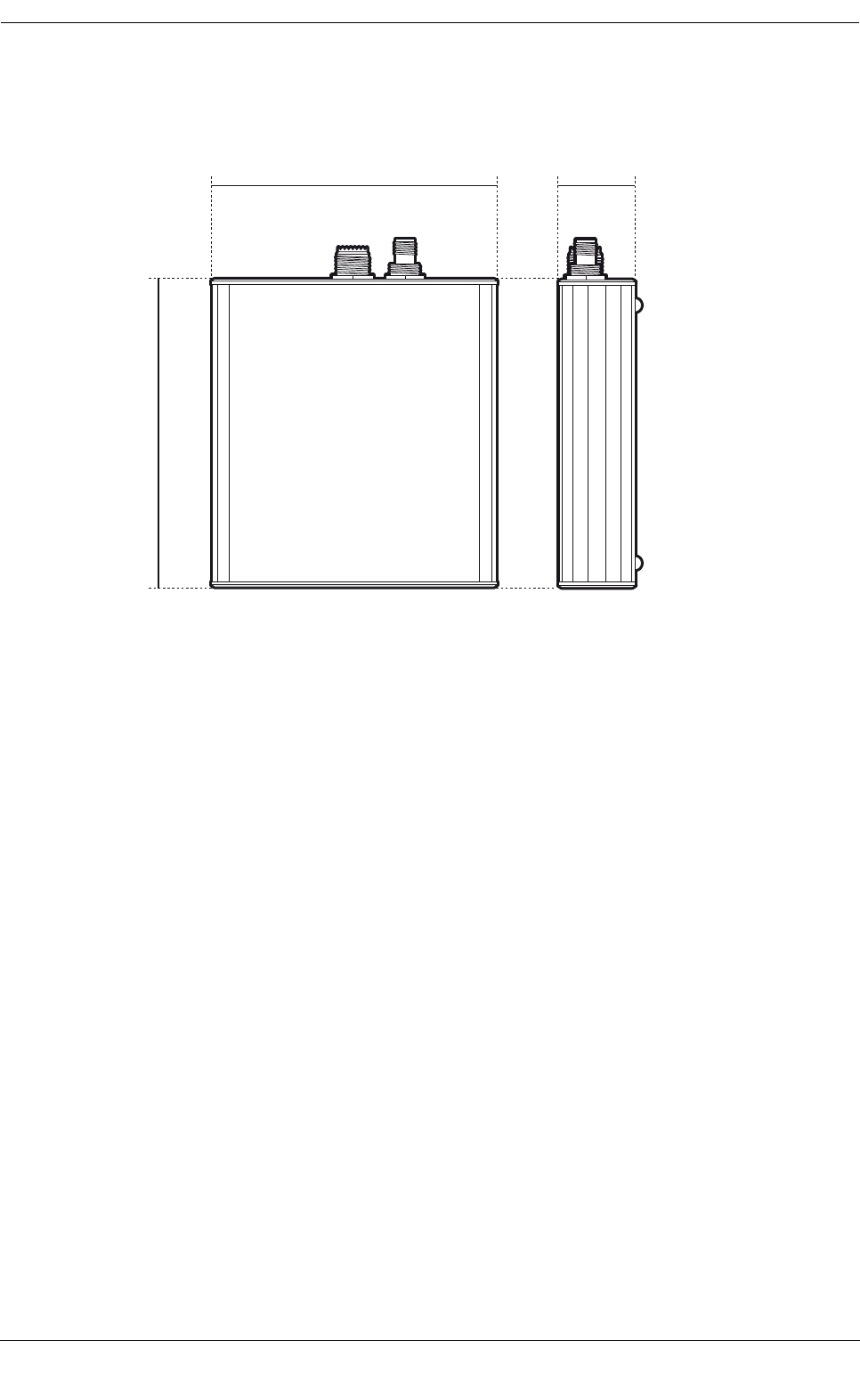
8.3 Drawings and dimensions
Figure 15 Transceiver dimensions
140 mm140 mm
130 mm 35 mm130 mm 35 mm

Warranty
Page 34
9 Warranty
SRT Marine System Solutions Ltd. is pleased to support your product (“Product”) with a limited Warranty (the
“Warranty”) as specifically described in this document. This Warranty does not affect your statutory consumer
rights.
The period of your Warranty is one calendar year commencing from the date of your purchase of the brand
new product from an authorised vendor (“Warranty Period”). In order to make a valid claim on your Warranty
you will require proof of purchase.
What your Warranty covers
SRT Marine System Solutions Ltd. warrants that, subject to correct storage, installation and use as instructed
in the Installation Manual, your Product will be substantially free from manufacturing and design defects for the
Warranty Period. In the unlikely event of a problem with your Product then you will need to follow the Warranty
claim process during which SRT Marine System Solutions Ltd. will determine the validity of your claim and the
action which needs to be taken. SRT Marine System Solutions Ltd.’s decision on all Warranty claims is final
and is limited in all respects to the repair or replacement of the product at SRT Marine System Solutions Ltd.’s
sole discretion.
What this Warranty does not cover
The Warranty does not cover the effects of normal wear and tear. The Warranty is immediately invalidated in
the event that the Product has been opened and or tampered with in any way or not stored, installed or used
as described in the Installation Manual, or subsequently issued directions from SRT Marine System Solutions
Ltd. This Warranty does not cover the data that is received by the Product as it is subject to external factors
out of SRT Marine System Solutions Ltd.’s control. This Warranty does not cover the product when, following
testing by SRT Marine System Solutions Ltd., it has been deemed to be damaged by any third party device.
How to make a Warranty claim
In the unlikely event of a problem you should first consult your Installation Manual to ensure that you have
followed all the instructions correctly. If you still wish to make a Warranty claim you will need to return the
Product to the SRT Marine System Solutions Ltd. vendor from where it was purchased who will process a claim
with SRT Marine System Solutions Ltd. on your behalf. If for whatever reason this is not possible then you
should contact SRT Marine System Solutions Ltd. directly by e-mail at enquiries@srt-marinesystems.com, or
via our web site, www.srt-marinesystems.com providing the date of purchase, vendor purchased from, exact
product model number, the product serial number and a detailed description of the problem. In all cases
SRT Marine System Solutions Ltd.’s decision on the validity of any Warranty claim and the remedy is final.
Limitation of liability
SRT Marine System Solutions Ltd.’s entire liability and responsibility is limited by the Warranty described
herein. The Warranty is non-transferable and therefore is only valid for the original purchaser of the new
product from an authorised SRT Marine System Solutions Ltd. vendor. Any additional Warranty offered by
vendors is entirely at their own risk unless specifically sanctioned by SRT Marine System Solutions Ltd. in the
form of a written commitment. SRT Marine System Solutions Ltd. is not liable for any direct, indirect,
consequential and or vicarious liabilities which may arise through your use of the Product, including but not
limited to any consequences resulting from the inability to use the Product and or misinterpretation and or
quality of the information generated by the Product. The entire extent of the liability from SRT Marine System
Solutions Ltd. to you in respect of the Product in all situations and respects shall be limited to the net amount
you paid for the Product from the original vendor.