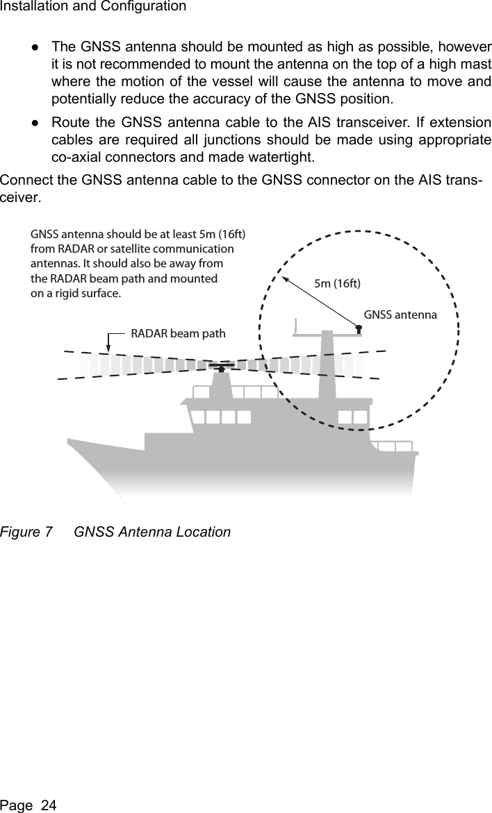
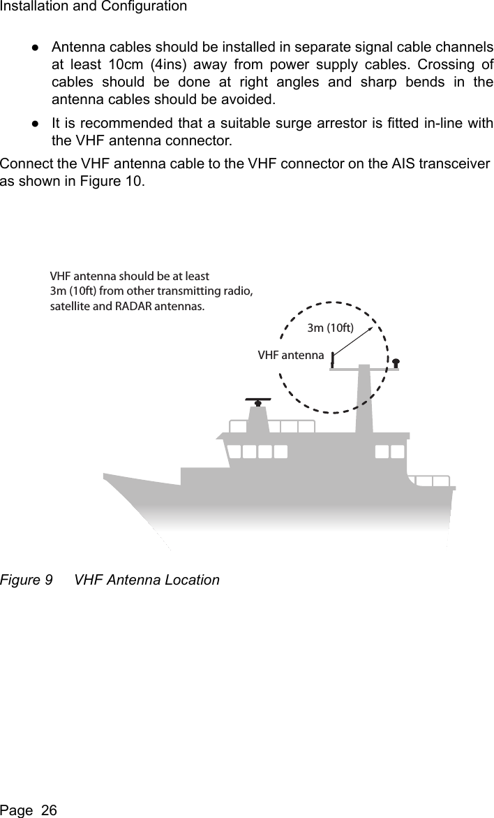
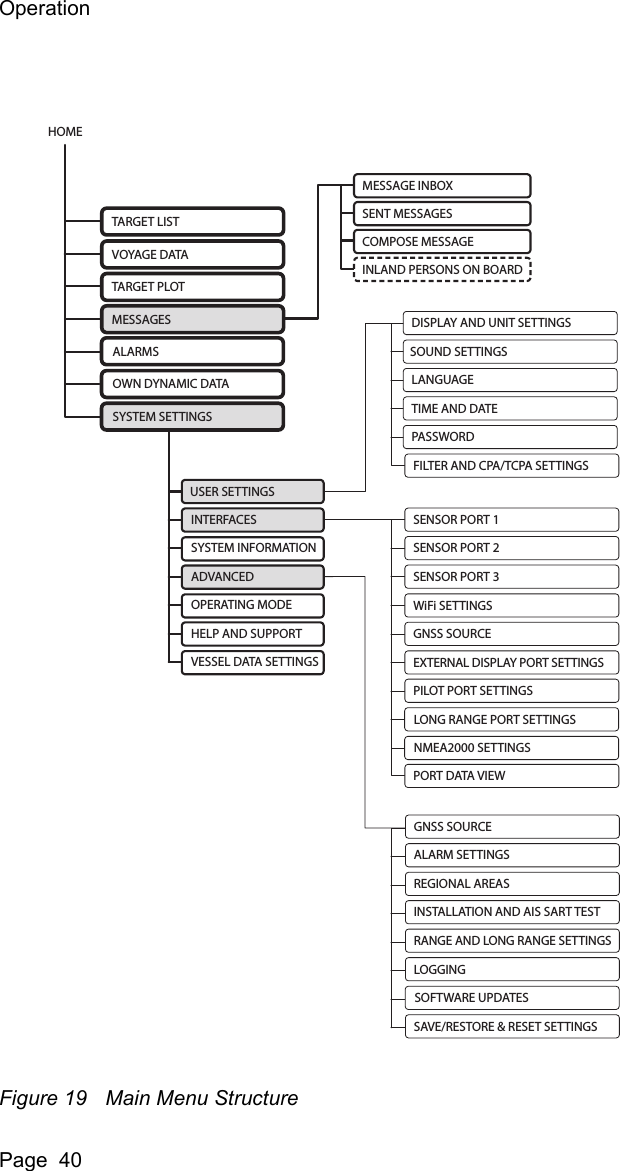
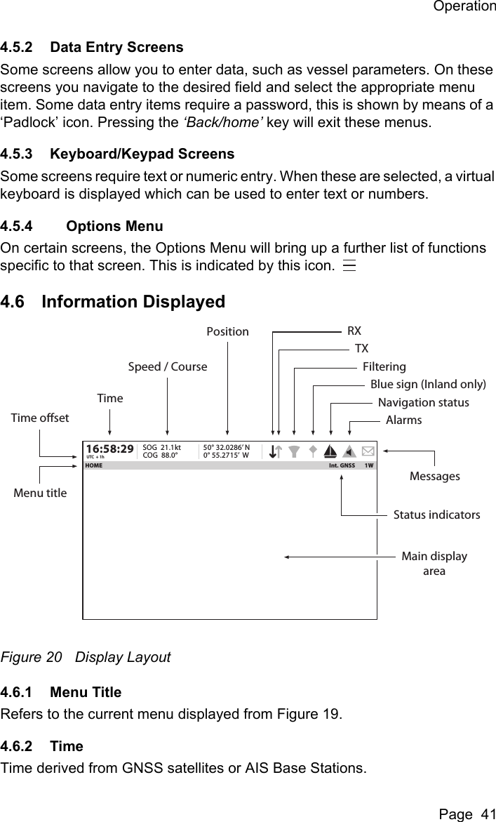
SRT Marine Systems plc 425-0002 Marine Class A AIS Transceiver with WLAN User Manual Apollo EN
Software Radio Technology plc Marine Class A AIS Transceiver with WLAN Apollo EN
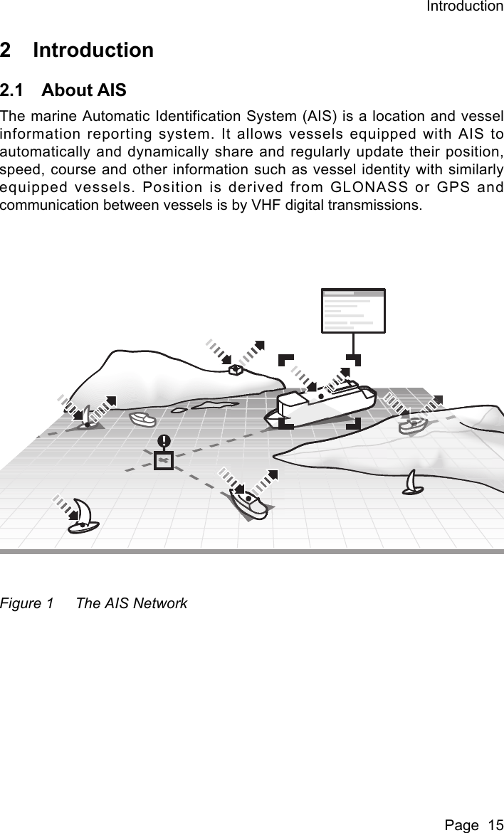
UserManual.wiki
>
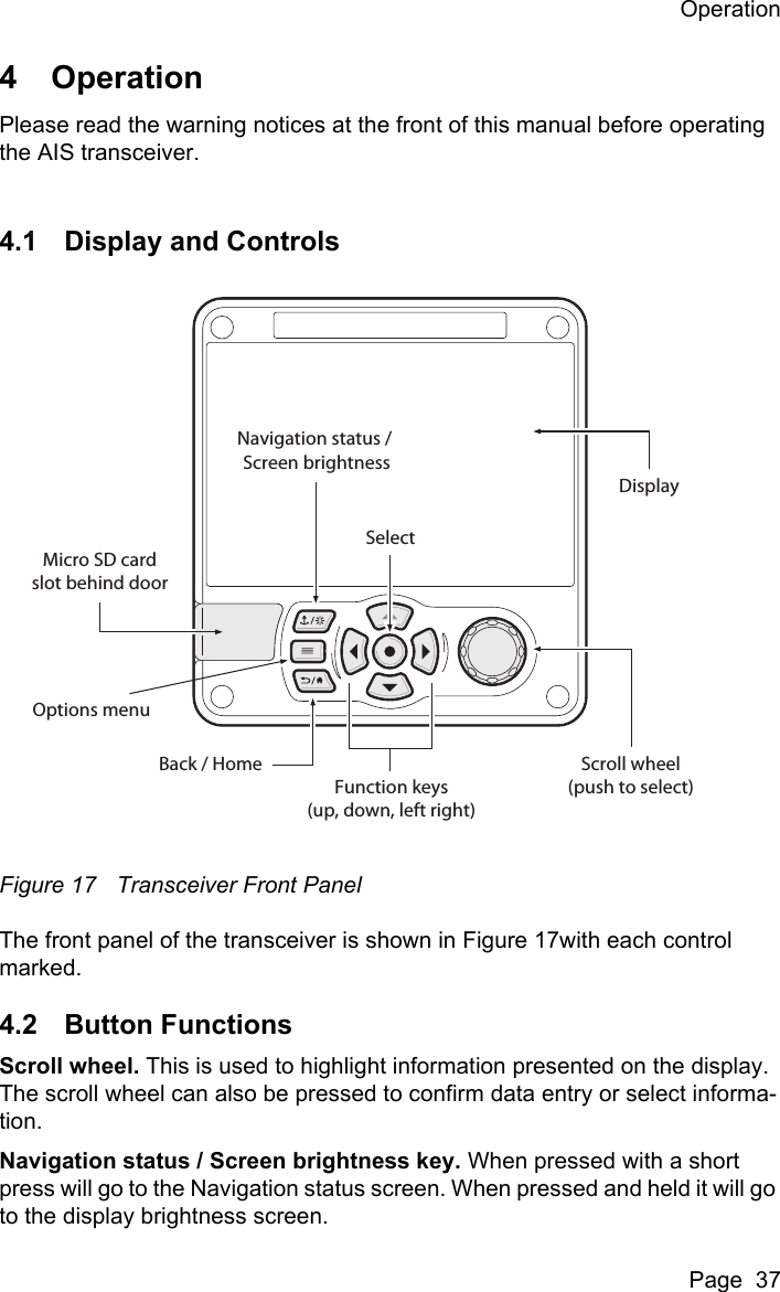
SRT Marine Systems plc
>
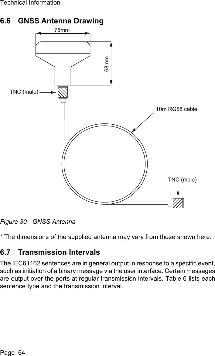
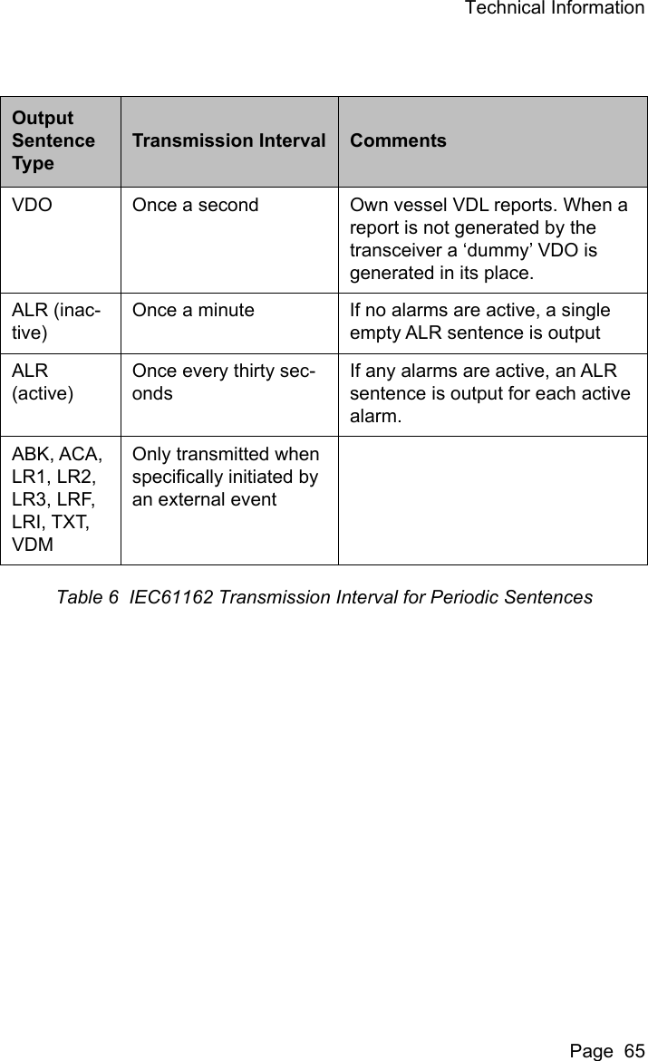
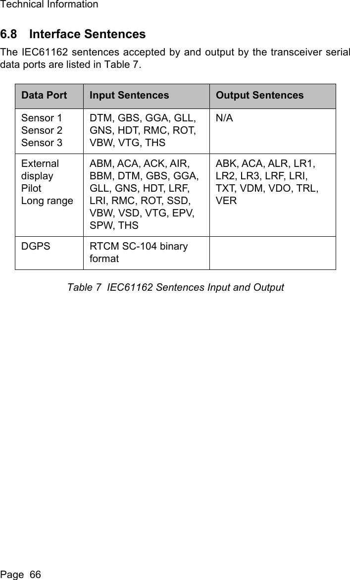
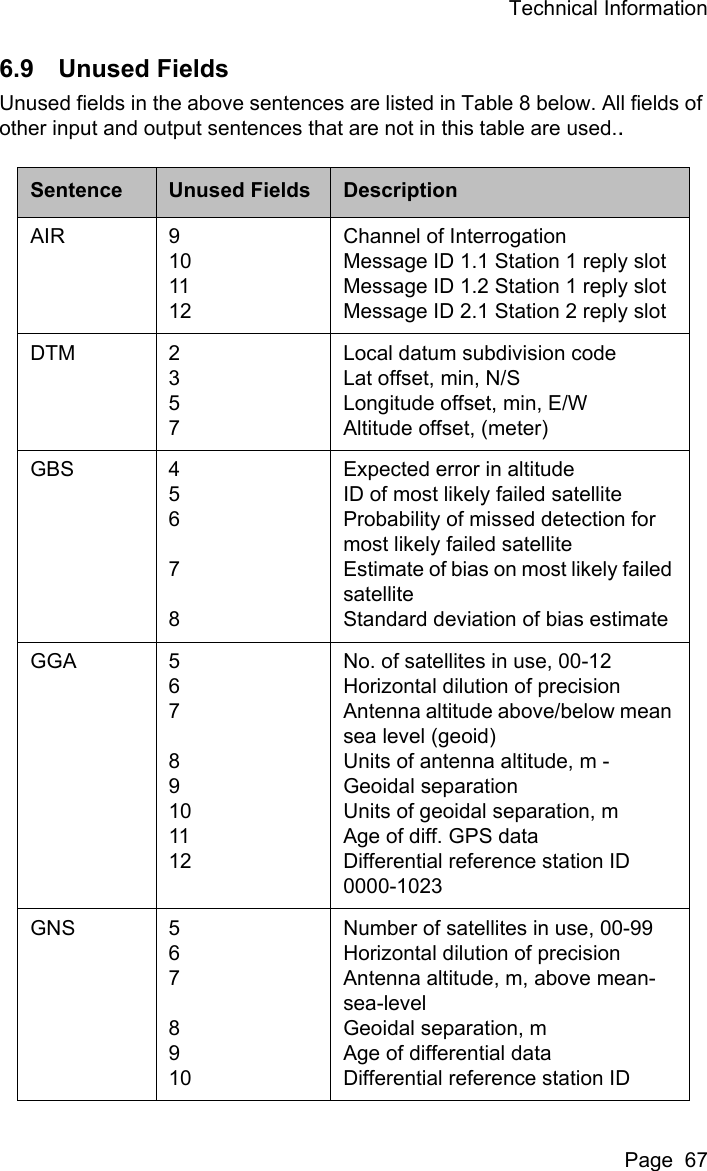
425 0002 User Manual
User Manual
Navigation menu
Upload a User Manual
Namespaces
Wiki Guide
HTML
PDF
Info
Views
User Manual
Discussion / Help
Navigation