SRT Marine Systems plc 425-0002 Marine Class A AIS Transceiver with WLAN User Manual Apollo EN
Software Radio Technology plc Marine Class A AIS Transceiver with WLAN Apollo EN
User Manual
AIS Class A / Inland Transceiver
Installation and Operation Manual
Thank you for purchasing this AIS Class A transceiver / Inland AIS.
This product has been engineered to offer you the highest level of perfor-
mance and durability and we hope that it will provide many years of reliable
service. We constantly strive to achieve the highest possible quality standards,
should you encounter any problems with this product, please contact your
dealer who will be pleased to offer any assistance you require.
List of abbreviations
Page 1
List of abbreviations
AIS Automatic Identification System
AIS SART AIS Search and Rescue Transmitter
AP Access Point (Relating to WiFi behaviour)
AtoN AIS Aid to Navigation
CD Compact Disc
CE European Declaration of Conformity
COG Coarse Over Ground
COM Common (electrical)
CPA Closest Point of Approach
CS Carrier Sense
DC Direct Current
Dec Decimal
DGPS Differential GPS
DGNSS Differential GNSS
DHCP Dynamic Host Configuration Protocol
DSC Digital Selective Calling
DTM Datum
ECDIS Electronic Chart Display and Information System
ENI Unique European Vessel Identification Number
EPFS Electronic Position Fixing System
ERI Electronic Reporting International
ETA Estimated Time of Arrival
EXT External
FCC Federal Communications Committee
GLONASS Globalnaya Navigazionnaya Sputnikovaya Sistema
GND Electrical Ground
GNSS Global Navigation Satellite System
List of abbreviations
Page 2
GPS Global Positioning System
Hex Hexadecimal
IEC International Electrotechnical Commission
IMO International Maritime Organisation
INT Internal
IPx6 Ingress Protection (to powerful water jets)
ISO International Standards Organisation
Kt Knots
LAT Latitude
LCD Liquid Crystal Display
LON Longitude
LR Long Range
MKD Minimum Keyboard and Display
MMSI Maritime Mobile Service Identity
NC Normally Closed (electrical)
NAV Navigation
NM Nautical Miles
NMEA National Marine Electronics Association
PGN Parameter Group Number
PI Presentation Interface
R&TTE Radio equipment and Telecommunications Terminal
Equipment
RADAR Radio Detection and Ranging
RAIM Receiver Autonomous Integrity Monitoring
ROT Rate of Turn
RX Receive
SD Secure Digital
SOG Speed Over Ground
List of abbreviations
Page 3
SOLAS Safety of Life at Sea
SRM Safety Related Message
TCP Transmission Control Protocol
TCPA Time to Closest Point of Approach
TNC Threaded Neill–Concelman (a type of connector)
TPI Threads per Inch
TX Transmit
UDP User Datagram Protocol
UHF Ultra High Frequency
UTC Universal Time Co-ordinated
VDO AIS own-ship broadcast data
VDM All VDL AIS messages received
VHF Very High Frequency
VSWR Voltage Standing Wave Ratio
WEEE Waste Electrical & Electronic Equipment
WiFi Wireless networking technology
List of abbreviations
Page 4
Table of contents
Page 5
Table of contents
1 Notices ............................................................ 11
1.1 Safety Warnings............................................................................. 11
1.2 General Notices ............................................................................. 12
1.3 Regulatory Statements .................................................................. 13
2 Introduction .................................................... 15
2.1 About AIS....................................................................................... 15
3 Installation and Configuration ...................... 17
3.1 What’s in the Box? ......................................................................... 17
3.2 Preparing for Installation ................................................................ 17
3.3 Installation Procedures .................................................................. 18
3.4 Connecting the Equipment............................................................. 27
3.5 Grounding the Transceiver ............................................................ 34
3.6 Connection to an NMEA2000 network (optional)........................... 34
3.7 Turning the Transceiver On ........................................................... 35
4 Operation ........................................................ 37
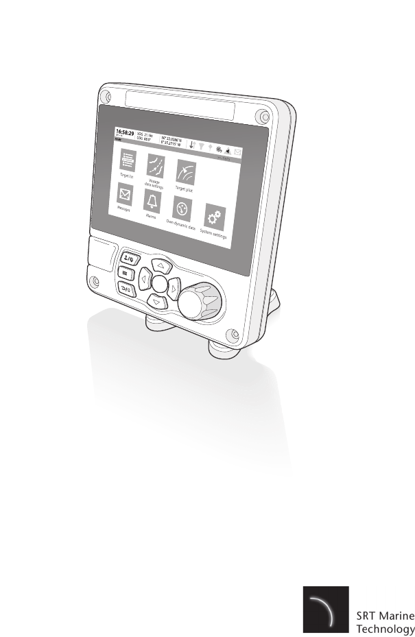
4.1 Display and Controls...................................................................... 37
4.2 Button Functions ............................................................................ 37
4.3 Adjusting Display Brightness ......................................................... 38
4.4 Changing Navigation Status .......................................................... 38
4.5 Menu Navigation ............................................................................ 39
4.6 Information Displayed .................................................................... 41
4.7 Configuring Vessel Information...................................................... 46
4.8 Configuring Voyage Information .................................................... 48
4.9 Passwords and Security ................................................................ 49
4.10 Confirming Correct Operation ........................................................ 49
4.11 Communication Test ...................................................................... 50
4.12 Displaying AIS Targets .................................................................. 51
4.13 Micro SD card data input ............................................................... 53
4.14 WiFi Feature .................................................................................. 55
5 Inland mode.................................................... 57
Table of contents
Page 6
5.1 Mode SOLAS / Inland AIS.............................................................. 57
6 Technical Information.................................... 61
6.1 Interface Circuits ............................................................................ 61
6.2 Output Drive Capability of Bi-directional Ports ............................... 62
6.3 DGNSS Port................................................................................... 62
6.4 Input Data Sentence Formats ........................................................ 63
6.5 AIS Transceiver Overall Dimensions ............................................. 63
6.6 GNSS Antenna Drawing ................................................................ 64
6.7 Transmission Intervals ................................................................... 64
6.8 Interface Sentences ....................................................................... 66
6.9 Unused Fields ................................................................................ 67
6.10 Proprietary Sentences.................................................................... 68
6.11 Priority of Sensor Ports .................................................................. 68
6.12 Compatibility Mode......................................................................... 70
6.13 Message 24 Content ...................................................................... 70
6.14 NMEA 2000 PGN List .................................................................... 71
6.15 Troubleshooting ............................................................................. 73
7 Junction Box Accessory ............................... 75
7.1 What’s in the Box ........................................................................... 75
7.2 Installation ...................................................................................... 75
7.3 Connecting External Equipment..................................................... 76
7.4 Technical Information..................................................................... 77
8 Technical Specification ................................. 79
8.1 Applicable Equipment Standards ................................................... 79
8.2 Product Category ........................................................................... 80
8.3 Physical.......................................................................................... 80
8.4 Environmental ................................................................................ 80
8.5 Electrical......................................................................................... 80
8.6 Display and User Interface............................................................. 81
8.7 Internal GNSS ................................................................................ 81
8.8 TDMA Transmitter.......................................................................... 82
8.9 TDMA receiver ............................................................................... 82
Table of contents
Page 7
8.10 DSC Receiver ................................................................................ 82
8.11 RF Connections ............................................................................. 83
8.12 Data interface................................................................................. 83
8.13 Power and Data Connector Information......................................... 84
8.14 Open Source Licences................................................................... 84
8.15 Product Versions............................................................................ 84
9 Installation Record......................................... 85
9.1 Vessel Details ................................................................................ 85
Table of contents
Page 8
List of figures and tables
Page 9
List of figures and tables
Figure 1 The AIS Network.................................................................. 15
Figure 2 What’s in the Box?............................................................... 17
Figure 3 Typical AIS Transceiver Connection.................................... 19
Figure 4 Mounting the Transceiver .................................................... 21
Figure 5 Desk Mounting the AIS Transceiver .................................... 22
Figure 6 Panel Mounting the AIS Transceiver ................................... 23
Figure 7 GNSS Antenna Location...................................................... 24
Figure 8 GNSS Antenna Connection ................................................. 25
Figure 9 VHF Antenna Location......................................................... 26
Figure 10 VHF Antenna Connection .................................................... 27
Figure 11 Serial Input Port Connection................................................ 28
Figure 12 14 way Connector Cable Wiring Connections ..................... 28
Table 1 14 way Connector Serial Data Ports.................................... 29
Figure 13 Serial Bi-directional Port Connection ................................... 30
Figure 14 18 way Connector Cable Wiring Connections ..................... 31
Table 2 18 way Connector Serial Data Ports.................................... 31
Table 3 Alarm Relay Connections .................................................... 32
Figure 15 Power Connection ............................................................... 33
Table 4 Power Supply Connections.................................................. 33
Figure 16 Grounding the Transceiver .................................................. 34
Figure 17 Transceiver Front Panel ...................................................... 37
Figure 18 Home Page Menu Screen ................................................... 39
Figure 19 Main Menu Structure ........................................................... 40
Figure 20 Display Layout ..................................................................... 41
Table 5 Alarms List ........................................................................... 44
Figure 21 Vessel Dimension Measurement ......................................... 47
Figure 22 Enter Password Screen ....................................................... 49
Figure 23 Target List Screen ............................................................... 51
Figure 24 AIS target symbols displayed .............................................. 52
Figure 25 Micro SD card Socket .......................................................... 54
Figure 26 Blue Sign Interface Connection Options.............................. 59
Figure 27 Input Port Schematic ........................................................... 61
Figure 28 Data Output Port Schematic ................................................ 62
Figure 29 Transceiver Dimensions ...................................................... 63
Figure 30 GNSS Antenna .................................................................... 64
Table 6 IEC61162 Transmission Interval for Periodic Sentences .... 65
Table 7 IEC61162 Sentences Input and Output ............................... 66
Table 8 Unused Fields...................................................................... 68
Table 9 Port Priority Order................................................................ 69
List of figures and tables
Page 10
Table 10 PGN Lists............................................................................. 72
Table 11 Troubleshooting ...................................................................74
Figure 31 Junction Box - What’s in the Box ......................................... 75
Figure 32 Connecting the External Equipment ....................................76
Figure 33 GNSS Antenna Position....................................................... 86

Notices
Page 11
1Notices
When reading this manual please pay particular attention to
warnings marked with the warning triangle symbol shown on the
left. These are important messages for safety, installation and
usage of the transceiver.
1.1 Safety Warnings
This equipment must be installed in accordance with the instructions
provided in this manual. Failure to do so will seriously affect its perfor-
mance and reliability. It is strongly recommended that a trained tech-
nician installs and configures this product.
This product must be connected to protective earth via the earth
connection point. It is essential that the earth connection point
is used in all installations, regardless of what other equipment is
connected. The earth connection point must be bonded to pro-
tective earth using as short a connection as possible.
This equipment is intended as an aid to navigation and is not a re-
placement for proper navigational judgement. Information provided by
the equipment must not be relied upon as accurate. User decisions
based upon information provided by the equipment are done so en-
tirely at the users own risk.
Do not install this equipment in a flammable atmosphere such as in
an engine room or near to fuel tanks.
It is recommended that this product is not installed in direct sunlight or
under a windshield where it can be subjected to excessive solar heat-
ing.
Do not attempt to service this equipment as doing so may cause fire,
electric shock or malfunction and will invalidate the warranty. If any
malfunctions are detected contact your supplier or service agent.
!
!
!
!
!
!
!

Notices
Page 12
NOT ALL SHIPS CARRY AIS. The Officer of the Watch should al-
ways be aware that other ships and, in particular, leisure craft, fishing
vessels and warships may not be fitted with AIS. Any AIS equipment
fitted on other ships as a mandatory carriage requirement may also
be off based on the Master’s professional judgement.
1.2 General Notices
1.2.1 Position Source
All marine AIS transceivers utilise a satellite based location system such as
the GLONASS or GPS satellite networks.
The accuracy of a GNSS position fix is variable and affected by fac-
tors such as the antenna positioning, how many satellites are used to
determine a position and for how long satellite information has been
received.
1.2.2 Compass Safe Distance
The compass safe distance of this transceiver is 0.5m or greater for a 0.3° de-
viation.
1.2.3 Product Category
This product is categorized as ‘protected’ in accordance with the definitions
provided in IEC 60945.
1.2.4 Disposal of Transceiver and Packaging
Please dispose of this AIS transceiver in accordance with the European
WEEE Directive or with the applicable local regulations for disposal of electri-
cal equipment. Please dispose of the packaging in an environmentally friendly
manner.
1.2.5 Accuracy of this Manual
This manual is intended as a guide to the installation, setup and use of this
product. If you are in any doubt about any aspect of this product, please con-
tact your dealer.
!
!

Notices
Page 13
1.3 Regulatory Statements
1.3.1 Declaration of Conformity - R&TTE
The manufacturer of this product declares that this product is in compliance
with the essential requirements and other provisions of the R&TTE directive.
The declaration of conformity is provided as a PDF file on the product CD sup-
plied with the product. The product carries the CE mark, notified body number
and alert symbol as required by the R&TTE directive. The product is intended
for sale in the following member states: Great Britain, France, Spain, Sweden,
Austria, Netherlands, Portugal, Denmark, Norway, Belgium, Italy, Finland, Ire-
land, Luxembourg, Germany and Czech Republic.
1.3.2 FCC Notice
This equipment has been tested and found to comply with the limits
for a class A digital device, pursuant to part 15 of the FCC Rules.
These limits are designed to provide reasonable protection against
harmful interference in a residential installation. This equipment gen-
erates, uses and can radiate radio frequency energy and, if not in-
stalled and used in accordance with the instructions, may cause
harmful interference to radio communications.
This device complies with part 15 of the FCC Rules. Operation is sub-
ject to the following two conditions:
(1)This device may not cause harmful interference, and
(2) this device must accept any interference received, including inter-
ference that may cause undesired operation.
Changes or modifications not expressly approved by the party re-
sponsible for compliance could void the user's authority to operate the
equipment.
!

Notices
Page 14
1.3.3 Industry Canada Notice
This device complies with Industry Canada licence-exempt RSS stan-
dard(s). Operation is subject to the following two conditions:
1.This device may not cause interference, and
2.This device must accept any interference, including interference
that may cause undesired operation of the device.
This Class A digital apparatus complies with Canadian ICES-003.
Le présent appareil est conforme aux CNR d'Industrie Canada appli-
cables aux appareils radio exempts de licence. L'exploitation est au-
torisée aux deux conditions suivantes:
1. L'appareil ne doit pas produire de brouillage, et
2. L'utilisateur de l'appareil doit accepter tout brouillage radioélec-
trique subi, même si le brouillage est susceptible d'en compromettre
le Fonctionnement.
Cet appareil numérique de la classe A est conforme à la norme NMB-
003 du Canada.
!
Introduction
Page 15
2 Introduction
2.1 About AIS
The marine Automatic Identification System (AIS) is a location and vessel
information reporting system. It allows vessels equipped with AIS to
automatically and dynamically share and regularly update their position,
speed, course and other information such as vessel identity with similarly
equipped vessels. Position is derived from GLONASS or GPS and
communication between vessels is by VHF digital transmissions.
Figure 1 The AIS Network
Introduction
Page 16

Installation and Configuration
Page 17
3 Installation and Configuration
3.1 What’s in the Box?
Please ensure all items are present and if any of the items are missing please
contact your dealer.
Figure 2 What’s in the Box?
3.2 Preparing for Installation
In addition to the items provided with the transceiver the following items will be
required to complete the installation:
3.2.1 VHF Antenna
Connection of a suitable VHF antenna will be required for the AIS transceiver
to operate. The antenna cable should be terminated with a PL-259 (or UHF)
connector. A surge arrestor should be fitted in line with VHF antenna connec-
tor. See section 3.3.3 for more information.
Mounting bracket
Power cable 14 way data cable 18 way data cable GNSS antenna and cable
Product CD
Product
manual
AIS transceiver
Fixings
Warranty card
Product Mounting
Template
Quick Start
Guide
Quick Operation
Guide
Installation and Configuration
Page 18
Please take note of the warnings listed at the start of this manual regarding the
installation and use of antennas.
3.2.2 Antenna Cables
The supplied GNSS antenna is provided with 10 metres (32.8ft) of cable. If this
is not sufficient to reach between the desired GNSS antenna location and the
AIS transceiver you will require an extension cable. Please contact your dealer
for details.
3.2.3 GNSS Antenna Mount
A mounting bracket is required for the supplied GNSS antenna.
3.2.4 Data Interface Cables
Suitable screened, multi core cable will be required to connect the ships sen-
sor (DGPS, Gyro etc.) data ports to the AIS transceiver.
3.3 Installation Procedures
Before beginning installation of your AIS transceiver, please ensure that you
read all of the instructions in this manual.
Installation and Configuration
Page 19
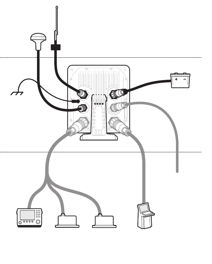
The following sections explain the installation process step by step for each of
the main system elements. A typical system and connection diagram is pro-
vided in Figure 3
Figure 3 Typical AIS Transceiver Connection
NMEA2000
Above decks
Below decks
Optional connections
Chassis/GND
GNSS antenna
VHF antenna
12/24V DC Supply
Displays
(ECDIS, RADAR)
Surge arrestor
Ship’s sensor data (DGPS, GYRO, Heading)
Installation and Configuration
Page 20
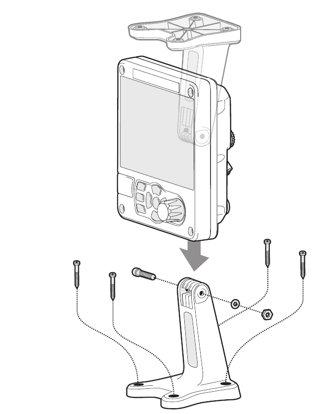
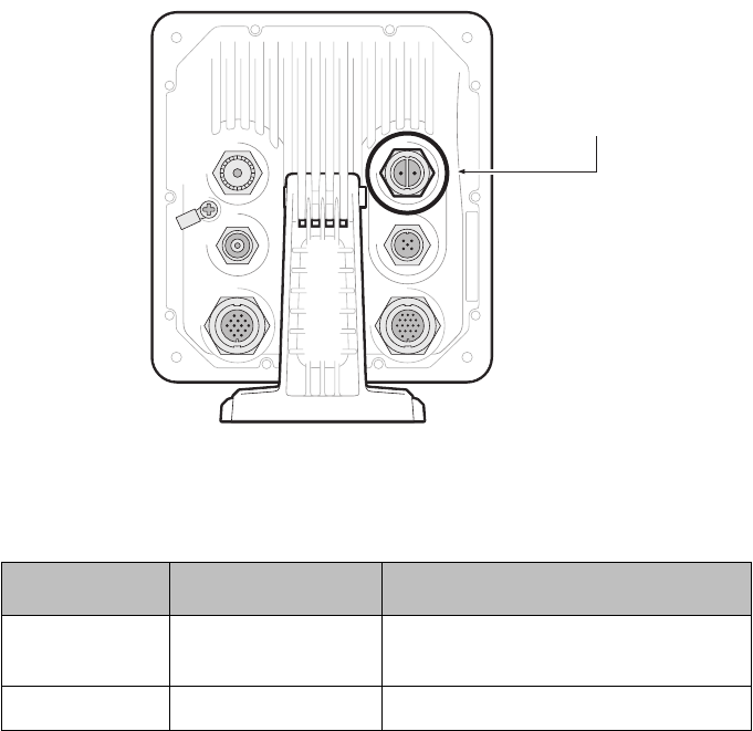
3.3.1 Step 1 - Installing the AIS Transceiver
Please note the following guidelines when selecting a location for your AIS
transceiver:
●The AIS transceiver must be fitted in a location where it is at least
0.5m (1ft 8ins) from a compass or any magnetic device.
●There should be adequate space around the AIS transceiver for
routing of cables. See Figure 29 for details of the AIS transceiver
dimensions.
●The ambient temperature around the AIS transceiver should be
maintained between -15°C and +55°C (5°F to 131°F). Ensure
adequate ventilation is present when panel mounting the transceiver.
●It is recommended that the AIS transceiver be installed in a 'below
decks' environment protected from the weather.
●The transceiver is supplied with four self tapping screws for
attachment of the AIS transceiver to a suitable surface using the
supplied bracket. Please refer to Figure 5 for guidance.
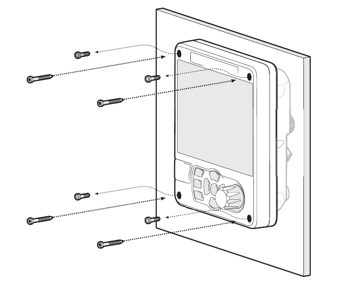
●The transceiver can be panel mounted using the four self tapping
screws provided. Please refer to Figure 6 for guidance. Access
behind the panel is required when using this mounting option.
●The AIS transceiver should be mounted in a location where the
display is visible to the user at the position from which the vessel is
normally operated.
A pilot plug connection option is included in the 18 way connector located on
the rear panel of the AIS transceiver. To provide the pilot plug an optional ac-
cessory can be purchased.
Installation and Configuration
Page 21
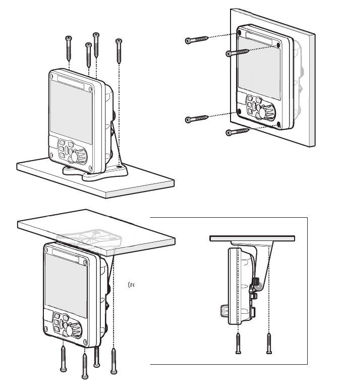
Figure 4 Mounting the Transceiver
Refer to Figure 29 for dimensions. A drilling and cutting template is provided
with the transceiver.
To panel mount the unit it is necessary to remove the 4 off socket cap screws
recessed in front of the unit. See Figure 6.
Desk mounted
Panel mounted
Overhead mounted
(reverse mounting bracket)
Installation and Configuration
Page 22
Figure 5 Desk Mounting the AIS Transceiver
Installation and Configuration
Page 23
Figure 6 Panel Mounting the AIS Transceiver
3.3.2 Installing the GNSS Antenna
For mounting the GNSS antenna supplied with your AIS transceiver you will
require a one inch 14 TPI pole mount. Contact your dealer to source a mount
suitable for the installation location.
Please note the following guidelines when selecting a location for the GNSS
antenna:
●The GNSS antenna mount should be secured to a rigid surface.
●The GNSS antenna should be located where it has a clear,
unobstructed view of the sky overhead.
Installation and Configuration
Page 24
●The GNSS antenna should be mounted as high as possible, however
it is not recommended to mount the antenna on the top of a high mast
where the motion of the vessel will cause the antenna to move and
potentially reduce the accuracy of the GNSS position.
●Route the GNSS antenna cable to the AIS transceiver. If extension
cables are required all junctions should be made using appropriate
co-axial connectors and made watertight.
Connect the GNSS antenna cable to the GNSS connector on the AIS trans-
ceiver.
Figure 7 GNSS Antenna Location
GNSS antenna should be at least 5m (16ft)
from RADAR or satellite communication
antennas. It should also be away from
the RADAR beam path and mounted
on a rigid surface.
RADAR beam path
GNSS antenna
5m (16ft)
Installation and Configuration
Page 25
Figure 8 GNSS Antenna Connection
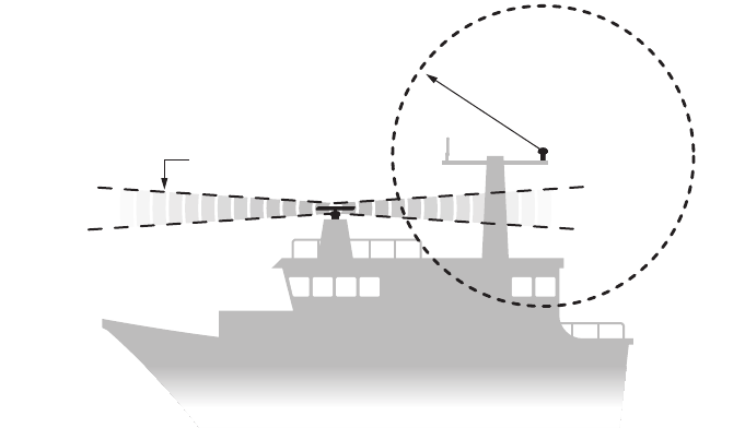
3.3.3 Installing the VHF Antenna
Please note the following guidelines when selecting and locating the AIS VHF
antenna:
●The VHF antenna should be located as high as possible and
positioned as far from other antennas as possible.
●The VHF antenna should have omnidirectional vertical polarization.
●Where possible the VHF antenna should be installed at least 3m
(10ft) away from other transmitting radio, satellite and RADAR
antennas.
●Ideally the AIS VHF antenna should be mounted directly above or
below the ship’s primary VHF radiotelephone antenna, with no
horizontal separation and with a minimum of 2m vertical separation.
Refer to Figure 9 for further guidance.
●The VHF antenna cable should be kept as short as possible to
minimize signal loss. High quality, low loss coaxial cable appropriate
to the installation location should be used.
●The VHF antenna cable should be terminated in a PL-259 co-axial
connector for connection to the AIS transceiver.
●Any outdoor installed connectors in the antenna cables should be
waterproof by design.
GNSS antenna
connection
Installation and Configuration
Page 26
●Antenna cables should be installed in separate signal cable channels
at least 10cm (4ins) away from power supply cables. Crossing of
cables should be done at right angles and sharp bends in the
antenna cables should be avoided.
●It is recommended that a suitable surge arrestor is fitted in-line with
the VHF antenna connector.
Connect the VHF antenna cable to the VHF connector on the AIS transceiver
as shown in Figure 10.
Figure 9 VHF Antenna Location
VHF antenna should be at least
3m (10ft) from other transmitting radio,
satellite and RADAR antennas.
3m (10ft)
VHF antenna
Installation and Configuration
Page 27
Figure 10 VHF Antenna Connection
3.4 Connecting the Equipment
3.4.1 Data Connections
The transceiver is supplied with a 2m (6.5 ft) 18 way data cable and a 2m (6.5
ft) 14 way data cable for connection of the transceiver to external sensors and
equipment.
3.4.2 Sensor Configuration
The transceiver has six NMEA0183 (IEC61162-1/2) data ports for connection
of ship’s sensors and display equipment as described in Table 1 and Table 2.
There are three input only ports for ship’s sensor data and three bidirectional
high speed ports for connection of display equipment such as Radar or elec-
tronic chart displays.
VHF antenna
connection
Installation and Configuration
Page 28
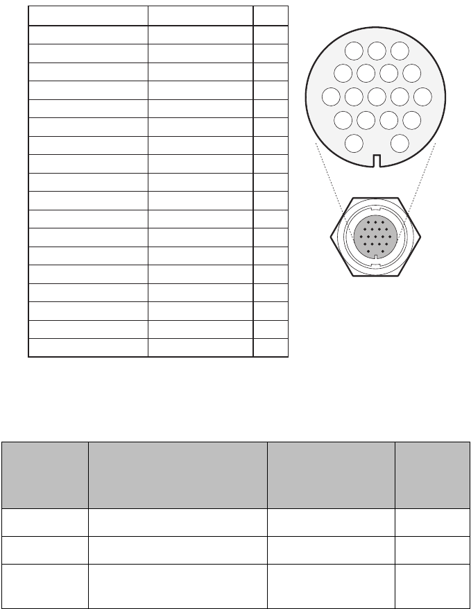
3.4.3 Data Input Ports (14 way connector)
Figure 11 Serial Input Port Connection
Figure 12 14 way Connector Cable Wiring Connections
14 way interface
connection
PIN
1
3
6
7
2
5
8
9
12
11
14
13
10
4
WIRE COLOUR
BLACK
BROWN
BLUE
RED
ORANGE
PURPLE
GREEN
WHITE
WHITE/BLACK
GREY
YELLOW
RED/BLACK
PINK
DRAIN WIRE
SIGNAL
BLUE SIGN N
BLUE SIGN P
SILENT N
SILENT P
SENSOR 1 RX A
SENSOR 1 RX B
SENSOR 1 COM
SENSOR 2 RX A
SENSOR 2 RX B
SENSOR 2 COM
SENSOR 3 RX A
SENSOR 3 RX B
SENSOR 3 COM
CHASSIS
9876
12 11 10
54 3
21
14 13

Installation and Configuration
Page 29
Table 1 14 way Connector Serial Data Ports
Note: Any unused ports should be terminated by a 120 Ohm resistor across
RX A and RX B signals.
3.4.4 Silent mode switch
To activate the Silent mode switch, apply a voltage of between 2V and 30V to
the SILENT P (Pin 7) and SILENT N (Pin 6) terminals of the 14 way connector.
Data port Function Type
Default
Baud
rate
1 Sensor 1 input
(DGNSS - COG/SOG/
LAT/LON)
Receive only 4800
2 Sensor 2 input
(Rate of Turn)
Receive only 4800
3 Sensor 3 input
(Gyro heading)
Receive only 4800
Installation and Configuration
Page 30
3.4.5 Data Bi-directional Ports (18 way connector)
Figure 13 Serial Bi-directional Port Connection
18 way interface
connection
Installation and Configuration
Page 31
Figure 14 18 way Connector Cable Wiring Connections
Table 2 18 way Connector Serial Data Ports
Note: Any unused ports should be terminated by a 120 Ohm resistor across
RX A and RX B signals.
Data port Function Type
Default
Baud
rate
4 External display / ECDIS Bi-directional 38400
5 Pilot port Bi-directional 38400
6 Long range/DGPS/Ext
Display
Bidirectional 38400
PINWIRE COLOURSIGNAL
LR DGPS TX A
LR DGPS TX B
LR DGPS RX A
LR DGPS RX B
LR DGPS COM
PILOT TX A
PILOT TX B
PILOT RX A
PILOT RX B
PILOT COM
ALARM NC
ALARM COM
EXT DISPLAY TX A
EXT DISPLAY TX B
EXT DISPLAY RX A
EXT DISPLAY RX B
EXT DISPLAY COM
CHASSIS
ORANGE
BROWN
PURPLE
BLUE
BLACK
RED
RED/WHITE
PINK
YELLOW
GREEN
GREY
WHITE
ORANGE/WHITE
BLACK/WHITE
BROWN/WHITE
YELLOW/WHITE
GREEN/WHITE
DRAIN WIRE
3
4
7
8
1
2
5
6
10
11
16
12
13
17
14
18
15
9
11 10 9 78
15 14 1213
65 34
18 16
21
17

Installation and Configuration
Page 32
All sensor ports can be configured via the Interface settings menu which can
be found under the ‘System settings’-> ‘Interfaces’ menu option.
The Interface settings menu also includes the ability to disable the requirement
for external GNSS sensors to provide a DTM (Datum) sentence.
3.4.6 Alarm Connections
The transceiver also provides connections to the alarm relay contacts. The
alarm relay connections are described in Table 3.
Table 3 Alarm Relay Connections
Alarm connection Function Contact rating
COM Alarm relay common
connection 2A at 220VDC or 60W
maximum
NC Alarm relay normally
closed connection
If an external GNSS device which does not provide a DTM
sentence is connected to the transceiver and the trans-
ceiver is configured to require DTM sentences, the exter-
nal GNSS data will not be accepted by the transceiver. If
no DTM sentence is required the WGS84 datum will be
used as a coordinate origin and the external GNSS de-
vice must be configured to output position using this da-
tum.
!
Installation and Configuration
Page 33
3.4.7 Power Connection
Power is connected to the transceiver via the supplied 2 way power cable as
shown in Figure 15.
Figure 15 Power Connection
Table 4 Power Supply Connections
*Connection to an emergency power source is an IMO requirement for SOLAS
vessels.
The power supply current ratings and recommended fusing or circuit breaker
currents are as follows:
●A 12VDC supply should be able to provide a peak current of 6.0A
and be fused at 10.0A.
Wire colour Function Connect to
Red Power supply + 12V or 24V DC power supply from
ships emergency power source*
Black Power supply - Power supply ground
Power connection
Installation and Configuration
Page 34
●A 24VDC supply should be able to provide a peak current of 4.0A
and should be fused at 6.3A.
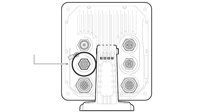
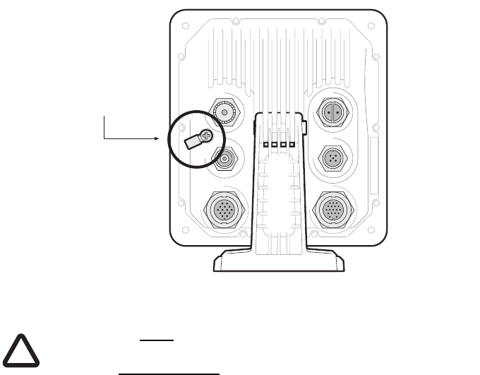
3.5 Grounding the Transceiver
An M4 grounding screw and ring crimp are provided in the fixing kit to allow
connection to the grounding point on the rear of the transceiver chassis as in-
dicated in Figure 16.
Figure 16 Grounding the Transceiver
This product must be connected to protective earth via the earth
connection point. It is essential that the earth connection point
is used in all installations, regardless of what other equipment is
connected. The earth connection point must be bonded to pro-
tective earth using as short a connection as possible.
3.6 Connection to an NMEA2000 network (optional)
The AIS transceiver can be connected to an NMEA2000 network by a suitable
NMEA2000 network cable available from your local dealer. If your vessel has
an NMEA2000 network please refer to the relevant documentation for you
NMEA2000 equipment. Once connected, and with your chart plotter also con-
nected you will be able to receive AIS targets on your chart plotter.
Ground screw
and ring tag
!
Installation and Configuration
Page 35
3.7 Turning the Transceiver On
The transceiver does not have an on/off switch and will operate immediately
that power is applied to the unit.
Installation and Configuration
Page 36
Operation
Page 37
4 Operation
Please read the warning notices at the front of this manual before operating
the AIS transceiver.
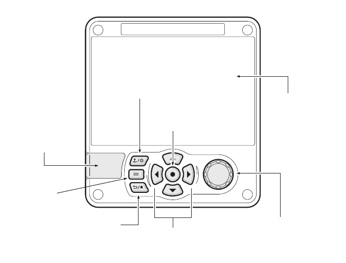
4.1 Display and Controls
Figure 17 Transceiver Front Panel
The front panel of the transceiver is shown in Figure 17with each control
marked.
4.2 Button Functions
Scroll wheel. This is used to highlight information presented on the display.
The scroll wheel can also be pressed to confirm data entry or select informa-
tion.
Navigation status / Screen brightness key. When pressed with a short
press will go to the Navigation status screen. When pressed and held it will go
to the display brightness screen.
Scroll wheel
(push to select)
Function keys
(up, down, left right)
Back / Home
Micro SD card
slot behind door
Navigation status /
Screen brightness
Select
Options menu
Display
Operation
Page 38
Options menu key. Provides access to additional features and relevant
shortcuts on certain screens.
Back / Home key. When pressed with a short press cancels the current oper-
ation and moves to the previous menu or if pressed and held will return to the
home screen.
Select key. When pressed selects the current option highlighted on the
screen.
Up, down, left and right function keys. Provide an alternative means of
navigating around the screen.
Speaker. The speaker is located behind the ‘Scroll’ wheel and can provide an
audible sound when a key is pressed, a message is received, or an alarm is
activated. Sounds can be enabled or disabled via the Sounds Settings menu.
Micro SD card. The micro SD card socket (behind the door) is provided to al-
low uploading of new software to the transceiver.
Display. The display shows essential AIS operating information and allows for
configuration of the transceiver via the menus.
4.3 Adjusting Display Brightness
Press and hold the ‘Navigation/Screen brightness’ key. The screen will
change to the Display and unit settings menu screen.
4.4 Changing Navigation Status
Press the ‘Navigation/Screen brightness’ key. The screen will change to the
Navigation menu screen. Move to the desired navigation status icon to select
it.
Operation
Page 39
4.5 Menu Navigation
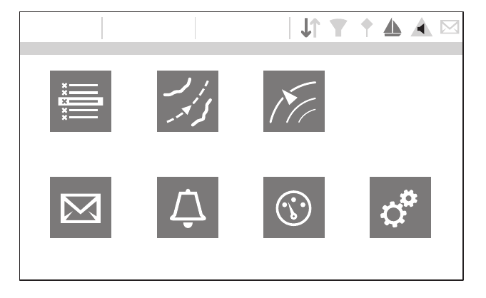
Figure 18 Home Page Menu Screen
4.5.1 Main / Sub Menus
Menus are displayed as a set of icons which can be navigated between using
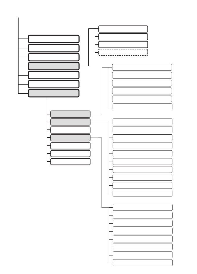
the controls. Selection of an icon will then display the information beneath in
accordance with Figure 19. Pressing the Back/home’ key will exit the menu.
HOME
16:58:29 SOG 21.1kt
UTC + 1h COG 88.0°
50° 32.0286’ N
0° 55.2715’ W
Target list Voyage
data settings Target plot
Messages Alarms Own dynamic data System settings
INT. GNSS
Operation
Page 40
Figure 19 Main Menu Structure
MESSAGE INBOX
SENT MESSAGES
COMPOSE MESSAGE
INLAND PERSONS ON BOARD
USER SETTINGS
INTERFACES
SYSTEM INFORMATION
ADVANCED
OPERATING MODE
HELP AND SUPPORT
VESSEL DATA SETTINGS
GNSS SOURCE
ALARM SETTINGS
REGIONAL AREAS
INSTALLATION AND AIS SART TEST
RANGE AND LONG RANGE SETTINGS
LOGGING
SOFTWARE UPDATES
SAVE/RESTORE & RESET SETTINGS
DISPLAY AND UNIT SETTINGS
SOUND SETTINGS
LANGUAGE
TIME AND DATE
PASSWORD
FILTER AND CPA/TCPA SETTINGS
WiFi SETTINGS
GNSS SOURCE
EXTERNAL DISPLAY PORT SETTINGS
PILOT PORT SETTINGS
LONG RANGE PORT SETTINGS
NMEA2000 SETTINGS
TARGET LIST
VOYAGE DATA
TARGET PLOT
MESSAGES
ALARMS
OWN DYNAMIC DATA
SYSTEM SETTINGS
PORT DATA VIEW
SENSOR PORT 1
SENSOR PORT 2
SENSOR PORT 3
HOME
Operation
Page 41
4.5.2 Data Entry Screens
Some screens allow you to enter data, such as vessel parameters. On these
screens you navigate to the desired field and select the appropriate menu
item. Some data entry items require a password, this is shown by means of a
‘Padlock’ icon. Pressing the ‘Back/home’ key will exit these menus.
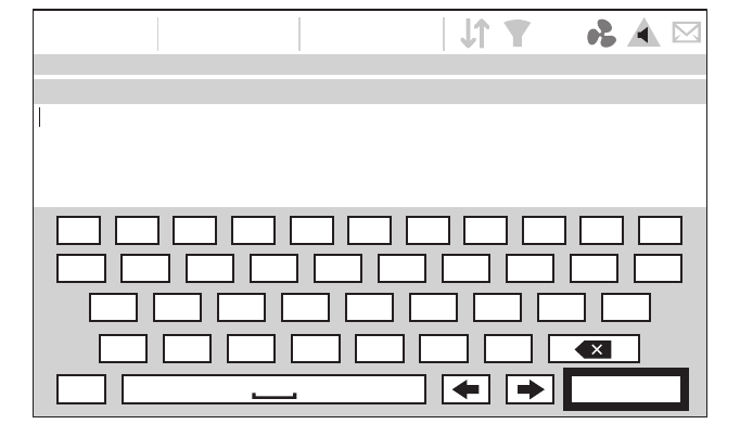
4.5.3 Keyboard/Keypad Screens
Some screens require text or numeric entry. When these are selected, a virtual
keyboard is displayed which can be used to enter text or numbers.
4.5.4 Options Menu
On certain screens, the Options Menu will bring up a further list of functions
specific to that screen. This is indicated by this icon.
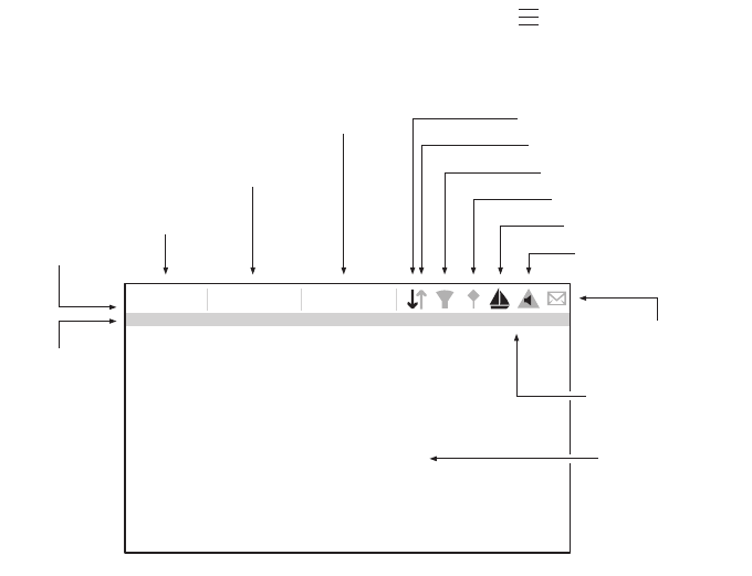
4.6 Information Displayed
Figure 20 Display Layout
4.6.1 Menu Title
Refers to the current menu displayed from Figure 19.
4.6.2 Time
Time derived from GNSS satellites or AIS Base Stations.
1WHOME Int. GNSS
16:58:29
SOG 21.1kt
UTC + 1h COG 88.0°
50° 32.0286’ N
0° 55.2715’ W
Speed / Course
Time
Time oset
Menu title
Main display
area
Status indicators
Messages
RX
TX
Filtering
Blue sign (Inland only)
Navigation status
Alarms
Position
Operation
Page 42
4.6.3 Time Offset
Offset from UTC, set on the ‘Time and date’ menu.
4.6.4 Speed/Course
Vessel speed and course as taken from GNSS satellite data.
4.6.5 Position
Vessel position taken from GNSS source.
4.6.6 Icons
RX - Illuminates to show receiving an AIS message.
TX - Illuminates to show transmission of an AIS message.
Filtering - Illuminated to show that target filter settings apply.
Blue sign - Inland only. Display of Blue Sign status.
Navigation status - Vessel navigation status.
Alarms - Displays an icon to show the presence of acknowledged or
unacknowledged AIS alarms.
Messages - Displays an envelope icon with a number to show the pres-
ence of AIS messages received See menu ‘Messages’.
Status indicators - Displays “INLAND” if in inland mode. Displays type of
GNSS being used and displays “1W” if the vessel power has changed to
1W.
4.6.7 Alarms
The transceiver performs self checking functions continuously. If a self check
fails a display will appear on the screen notifying the operator of this. This will
be accompanied by a sound. The alarm can be acknowledged via an on-
screen message. The list of currently active AIS Alarms can be displayed by
accessing the ‘Alarms’ menu. If any alarm condition persists, contact your
dealer or installer.

Operation
Page 43
Possible alarm conditions are listed Table 5:
Alarm Description
TX Malfunction This alarm will occur if the MMSI has not
been configured.
This alarm can also occur if the radio hard-
ware has failed to select the correct fre-
quency, that the output power is too low or a
transmitter shutdown has occurred.
In this situation, ALR 001 is output over the
PI.
The alarm will be cleared if the transmitter
recovers normal operation.
RX Channel x Malfunction This alarm occurs should the receiver hard-
ware malfunction. The receiver is identified
by the value of x (as shown below).
The following alarms will be generated over
the PI in this condition:
ALR 003 - Rx Channel 1
ALR 004 - Rx Channel 2
ALR 005 - DSC (Channel 70)
If the receiver returns to normal operation this
alarm will be cleared.
Antenna VSWR exceeds
limit
This alarm occurs if there is a problem with
your antenna or antenna connection.
External EPFS lost This alarm occurs if the position from the
external Electronic Position Fixing System
(i.e. GNSS) is invalid or lost.
No valid COG information This alarm occurs if the transceiver has no
valid Course Over Ground information from
any connected sensor.
No valid SOG information This alarm occurs if the transceiver has no
valid Speed Over Ground information from
any connected sensor.
Heading lost or invalid This alarm occurs if the transceiver has no
valid heading information from any con-
nected sensor, or if the heading is undefined.

Operation
Page 44
Table 5: Alarms List
No valid ROT information This alarm occurs if the transceiver has no
Rate Of Turn information from connected
sensors or via internal calculation.
No sensor position in use This alarm occurs if the transceiver has no
valid position information from any connected
sensor.
UTC Sync Invalid This alarm indicates that the transmitter is no
longer directly synchronized with the GNSS
receiver. This may be because the GNSS
receiver cannot receive sufficient satellites.
Nav Status Incorrect NavStatus incorrect
This alarm will occur if the navigation status
is in conflict with the current speed of the ves-
sel. For example the alarm will activate if the
Navigation status is set to moored, but the
vessel speed is greater than 3 knots. Correct
the navigation status to clear this alarm.
Active AIS SART An active AIS SART (AIS Search and Res-
cue Transmitter) message has been
received. The SART will be displayed as the
top item in the target list. Select this item to
see the location of the SART.
Internal / External GNSS
mismatch
This alarm occurs if the difference in position
reported by the internal and external GNSS
receivers is too large. Check the vessel
dimensions and GNSS antenna locations
have been entered correctly.
Heading sensor offset This alarm occurs if the difference between
the course over ground and heading data is
greater than 45° for more than 5 minutes.
This alarm only occurs if the vessel speed
over ground is greater than 5 knots.
Alarm Description

Operation
Page 45
4.6.8 Messages
AIS text messages and Safety Related Messages (SRMs) can be received
from other AIS equipped vessels and also sent to specific vessels (addressed
messages) or sent to all vessels in range (broadcast messages).
Reception of an AIS text message is indicated by the presence of the message
icon at the top of the screen. This icon is shown whenever there are unread
AIS text messages. Messages can be reviewed and replied to via the In-box.
The transceiver can store up to a maximum of 20 messages in the In-box and
20 messages in the Sent folder. If the number of messages exceeds 20 then
the oldest message will be overwritten.
When a Safety Related Message is received the user will be notified immedi-
ately with a pop-up showing the message. Standard text messages are not
displayed on receipt, however the message icon will be displayed at the top of
the screen.
AIS messages can be viewed, created and transmitted from the ‘Messages’
menu.
The available options are:
Compose - takes you to the message composition screen
In-box - takes you to the received message list view
Sent - shows a list of recently sent messages.
To compose a new message, select the type of message from the drop down
menu and the destination. This can be by directly entering the MMSI, or by se-
lecting from a list of visible targets.
The message text is entered using the on screen keyboard. Messages are lim-
ited to 80 characters in length.
Class B transceivers are permitted to receive broadcast SRMs
and broadcast text messages, however this function is not man-
datory. Class B transceivers are not able to receive addressed
SRM or text messages. There is therefore no guarantee that text
messages or SRMs sent to a Class B transceiver will be received.
4.6.9 Long Range Messages
If the transceiver is connected to a long range communication system via the
long range communications port then long range interrogations may be re-
ceived. These are requests for information from a distant base station beyond
normal AIS operation range.
The transceiver can be configured to automatically respond to Long Range
(LR) interrogations, or you can opt to respond to any interrogation manually.
!
Operation
Page 46
Automatic response is the default setting, but this can be changed on the ‘Ra-
dio and Long Range Settings’ menu.
When a Long range interrogation is received you will be alerted by an on-
screen pop-up message.
In automatic response mode simply review and acknowledge the notification
screen using ‘Acknowledge’. In manual response mode you should review the
request and select either the ‘Respond’ or ‘Decline’ option as appropriate.
4.6.10 Help and Support Screen
This screen is available from the ‘System Settings’ menu and provides contact
information for the product manufacturer.
It also provides relevant information from the User Manual.
4.6.11 User Settings Screen
From this screen, it is possible to set the display brightness, set the display to
a day or night colour scheme, set the operating units to metric or nautical, and
configure the sounds emitted by the device. It is also possible from this screen
to set the UTC time offset, change the password, change the filter settings and
display the menus in a number of non-English languages.
4.7 Configuring Vessel Information
4.7.1 Pre-configuration Checks
To proceed with configuration the steps in Section 3 should already have been
completed.
4.7.2 Configuring Vessel Identification Information
The transceiver must be configured with information about the vessel on which
it is installed prior to operation. The following information is required to be en-
tered in the ‘Vessel data settings’ menu:
●MMSI - Vessel MMSI number, this can usually be found on the ships
VHF radio license and should be the same MMSI as used for the
VHF / DSC radio.
●Ship Name (limited to 20 characters)
●Call sign - Vessel radio call sign (limited to 7 characters)
●IMO - Vessel’s IMO identification number (if applicable)
●Ship type - Selected from the menu provided.
●Dimensions of the location of the GNSS antenna connected directly
to the AIS transceiver (Internal GNSS)
Operation
Page 47
●Dimensions of the location of an optional GNSS antenna connected
to the AIS transceiver via an NMEA interface.
4.7.3 Configuring the Internal GNSS Receiver
The internal GNSS receiver can be configured to operate in one of three
modes:
●GLONASS and GPS – in this mode the position fix is derived from
both the GLONASS and GPS network in parallel. This mode is the
default setting and gives the best performance.
●GPS – in this mode only GPS satellites are used for the position fix.
●GLONASS – in this mode only GLONASS satellites are used for the
position fix.
The operating mode can be selected from the ‘GNSS source’ option in the ‘Ad-
vanced’ settings menu.
The antenna dimensions should be entered in metres according to the dia-
gram provided in Figure 21.
Figure 21 Vessel Dimension Measurement
Ref A
Antenna
Ref A + Ref B = Length in metres Ref C + Ref D = Beam in metres
Ref B
Stern Bow
Ref C
Ref D
Operation
Page 48
4.8 Configuring Voyage Information
4.8.1 Configure Voyage Related Data
The transceiver must be configured with information about its voyage prior to
operation. To enter the vessel identification information select the ‘Voyage
Data settings’ option.
The following information is required:
●Navigation Status - Navigational status selected from the icons on
the screen.
●Destination - Ships next destination port (limited to 20 characters).
●ETA - Estimated time / date of arrival at destination (using UTC time).
●Draught - Maximum present static draught to the nearest 1/10th of a
metre.
●Persons on Board - Number of crew on board (optional).
Operation
Page 49
4.9 Passwords and Security
Certain important information stored within the transceiver cannot be changed
without knowledge of the password. When trying to edit any of this protected
information you will be prompted to enter the password.
The password entry screen is shown in Figure 22. Highlight the required char-
acter, then press ‘Select’ to enter that character. When all characters of the
password have been entered, select ‘OK’.
Figure 22 Enter Password Screen
Following configuration of the transceiver the password should be changed
from its default value of ‘0000’ (four zeros) to another alpha numeric code.
Password change is carried out by selecting ‘User Settings’ -> ‘Password’.
The password should be recorded on the installation record found in Section 9.
4.10 Confirming Correct Operation
Following entry of the vessel and voyage information the transceiver will com-
mence normal operation. Correct operation should be verified as follows:
1. Select the ‘Own dynamic data’ option from the main menu.
16:58:29 SOG 21.1kt
UTC + 1h COG 88.0°
50° 32.0286’ N
0° 55.2715’ W
PASSWORD SETTINGS
Enter the current password:
1234567890 .
QWE R T Y U I O
A
ZXCVBNM
!? OK
P
SDFGHJ KL
Operation
Page 50
2. Check that the displayed position, course, speed and heading are cor-
rect by comparing to the display associated to the connected position
source and other data sources.
3. Check that the ‘TX’ icon flashes periodically.
4. If the vessel is in an area where other AIS equipped vessels are pres-
ent press the ‘Back / Home’ key and select ‘Target list’ to check that
data from other AIS equipped vessels is displayed.
5. Go to the ‘System settings / System Information’ screen and select
‘Hardware status’, check that the supply voltage and antenna VSWR
are correct.
The transceiver is now operational and should remain powered unless autho-
rised by the local maritime authority. The installation record at the rear of this
manual should be completed and left on board the vessel.
4.11 Communication Test
It is possible to conduct an AIS communication test with another AIS equipped
vessel. This test sends an AIS message to another vessel and checks for a
response. The transceiver will display a list of vessels from which one can be
selected for a communication test.
This feature can be selected from the ‘Advanced Settings’-> ’Installation and
AIS SART Test’ menu.
From this screen you can also switch on or off the display of test messages
from AIS Search and Rescue Transceivers. If ‘Display AIS SART Test Mes-
sages’ is set to On, messages from AIS SARTs in Test mode will be displayed.
Operation
Page 51
4.12 Displaying AIS Targets
4.12.1 Target List
The Target List Screen is the primary screen for displaying AIS targets re-
ceived. This is the first screen displayed when the unit is switched on, but can
also be accessed from the Target List option on the main menu.
Figure 23 Target List Screen
By default the target list is sorted by range but can be sorted on any column
by using the left and right ‘Function’ keys to select a column and pressing the
'Select' key to sort either in ascending or descending order. Navigation up and
down the list is via the up and down arrow keys or scroll wheel. Selecting a
highlighted target using the Select key will bring up more details of that target.
The Options menu on this screen provides additional actions which can be
performed on the target list.
Different symbols are shown for an AIS target depending on the type of target
and its status, these are shown in Figure 24. These symbols are common to
the Target list and Target plot displays.
NAME/MMSI Range Bearing CPA TCPA Type Age
TARGET LIST
16:58:29 SOG 21.1kt
UTC + 1h COG 88.0°
50° 32.0286’ N
0° 55.2715’ W
DUBLIN FISHER 1m 50s
B
B
BS
PROXIMITY CRAFT 1m 47s
ATLANTIC PRIDE 0m 1s
212222222 0m 36s
EMSLAKE 0m 45s
PIER 4 0m 6s
444110175
3.15NM
15.5NM
6.9NM
6.7NM
-
5.2NM
35.8NM
3.15NM
15.5NM
6.9NM
6.7NM
-
5.2NM
35.8NM
-
-
-
-
-
5h 38m
-
120.80
22.60
37.20
313.40
-
86.60
167.300m 5s
Visible: 12 Filtered out: 0
INT. GNSS
Operation
Page 52
Figure 24 AIS target symbols displayed
4.12.2 Target Filtering
From the Target List options menu, if 'Show Filter Settings' is selected, a
screen is displayed indicating which filter parameters can be set to reduce the
amount of data displayed on screen. This screen can also be accessed
through ‘System Settings’-> ‘User Settings’.
Filters can be toggled on and off on the target list by pressing the
‘Options menu’ key and selecting ‘Toggle filters off’. The bottom line
of the target list shows how many targets are visible or filtered out. If
a filter is set, the filter icon is displayed at the top of the screen.
The Filters icon does not represent CPA/TCPA alarm settings.
4.12.3 CPA/TCPA Settings
The transceiver can be configured to filter out approaching vessels which fall
within certain limits. The Closest Point of Approach (CPA) defines a boundary
around the own vessel upon which, if breached, will trigger the filter. Time to
Closest Point of Approach (TCPA) can only be set if CPA is set, and will trigger
the filter if the time to the CPA limit is breached.
These parameters are set on the ‘Filtering and CPA/TCPA Settings’ menu.
The target list shows targets which trigger the TCPA/CPA filter red.
These CPA/TCPA figures are calculated solely on AIS data and should not be
used for anti-collision purposes.
Note: Setting the CPA/TCPA filter will not activate the Filters Icon.
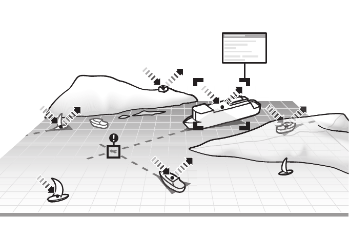
4.12.4 Target Plot
The Target Plot screen shows the location of other AIS equipped vessels and
shore stations relative to your own vessel. The target plot screen provides a
basic overview of AIS targets and should not be regarded as a substitute for
AIS Class A
O Position AtoN
Base station
AIS SART
AIS SAR Aircraft
O Position AtoN
B
BS
AIS Class B
AIS AtoN
Operation
Page 53
display of AIS information on a dedicated electronic chart display system (EC-
DIS).
The plot range can be adjusted by rotating the scroll wheel which cycles
through the ranges 0.2NM up to 100NM. The range relates to the radius of the
outer range ring shown on the screen.
Individual targets can be selected by using the arrow keys. When selected a
square outline will appear around the target and the vessel details will be
shown on the left hand side of the screen.
By pressing the options menu key, additional display features can be selected.
If the Own Vessel Details option is selected the left hand side of the screen will
change to show own vessel dynamic data.
If the MOB Details Display option is selected, the target plot will change to
show only AIS-MOB, AIS-SART, and AIS-EPIRB devices. The left hand side
of the screen will show the range and relative bearing to whichever target is
currently highlighted using the arrow keys.
4.13 Micro SD card data input
On the front of the transceiver under the door on the lower left hand side is a
socket for a Micro SD memory card. See Figure 25. This can be used to up-
grade the unit firmware or to log port data. Note the orientation of the Micro SD
card, which is critical to ensure the product is not damaged.

Operation
Page 54
Figure 25 Micro SD card Socket
4.13.1 Upgrading the Unit Firmware
If a Micro SD card that contains valid upgrade firmware is inserted into the card
socket, the unit will recognize the new firmware and will display a message
asking you if you want to install it. The system will guide you to the appropriate
menu screen, where the firmware update can be applied.
4.13.2 Logging Ports to the Micro SD card
If a Micro SD card is inserted into the card socket, the AIS transceiver can be
configured to output specific data to the card. This is accessed from the indi-
vidual port menu (from the ‘System settings’ -> ‘Interfaces’ menu.) If the ‘Log
port to SD Card’ option is set to ‘On’, data will be output from that port to the
Micro SD card, if one is inserted into the card socket. Only one port can be
logged to the Micro SD card at a time.
4.13.3 Saving/Loading Settings
From the ‘Save/Restore & reset settings’ menu, all system settings and trans-
ceiver configuration data can be saved to the Micro SD card, if one is inserted
Operation
Page 55
into the card socket. Settings previously saved can be restored, thus restoring
the transceiver to a previous configuration. ‘Reset settings’ will restore the unit
to its factory defaults and is protected by the unit password.
4.14 WiFi Feature
The AIS transceiver provides features to operate with vessel WiFi networks,
or to create its own network. Access the WiFi menu through ‘Interfaces’ -> ‘Wi-
Fi settings’.
4.14.1 Client Mode
If client mode is selected, the transceiver will search for available WiFi net-
works to connect to. If one is selected a password may be required, and upon
connection the details of the connection will be shown in the bottom right cor-
ner of the screen. Once a WiFi connection is made, the transceiver will output
a range of NMEA sentences over the selected WiFi port.
4.14.2 Access Point Mode
If the transceiver is configured as a WiFi access point (AP) it will create its own
WiFi network, allowing other WiFi enabled devices to connect to it. Once con-
nections are made, a range of NMEA sentences will be transmitted from the
transceiver to any connected devices.
4.14.3 Advanced WiFi Features
Within the ‘WiFi’ screen, certain parameters can be changed such as Channel
Number, Protocol, Port, Encryption, etc. These are recommended for ad-
vanced users only.
WiFi is switched off by selecting ‘Disable’ in the ‘Select Operating mode’ box.
Operation
Page 56

Inland mode
Page 57
5 Inland mode
5.1 Mode SOLAS / Inland AIS
The transceiver supports both standard ‘high seas’ operation and ‘Inland AIS’
operation. Inland AIS is an extension of AIS intended for use on board vessels
navigating Inland waterways.
5.1.1 Switching between ‘Class A’ and ‘Inland AIS’ Modes
To switch between operating modes select the ‘System settings' -> ‘Operating
mode’ option. Set the ‘Operating mode’ setting to ‘Inland AIS’ or ‘Class A /SO-
LAS’ before saving the setting. When the transceiver is configured to operate
in Inland AIS mode the word ‘INLAND’ is shown permanently in the Menu title
bar.
5.1.2 Entering Inland vessel identification settings
Additional vessel identification information is required for Inland operation
along with some changes to the standard AIS configuration. The following ad-
ditional information must be entered into the AIS transceiver:
●A quality setting for the speed, course and heading data sources
connected to the AIS is required. The quality setting can be ‘high’ or
‘low’ for each data source. The low setting should be used unless a
type approved sensor (e.g. a gyro providing heading information) is
connected to the AIS transceiver.
The additional identification information can be entered via the ‘Vessel data
settings’ menu.
The following standard AIS vessel identification information must be updated
for Inland AIS:
●The vessels ENI - this is an 8 digit number allocated to the vessel.
●The ship type as an ERI selected from the menu provided.
●The length and beam of the ship to the nearest 10cm (greater
accuracy than standard AIS configuration).
These updates are all made using the process described in section 4.7.2
!
The information entered and transmitted in Inland mode is
not the same as that transmitted in SOLAS mode. After
switching modes, please check your voyage and vessel
data settings to ensure the configuration is correct.

Inland mode
Page 58
5.1.3 Entering Inland Vessel Voyage Settings
Additional voyage related information is required for Inland operation along
with some changes to the standard AIS configuration. The following additional
information must be entered into the AIS transceiver:
●The vessel’s load status (Loaded, Unloaded, or Unknown).
●The number of blue cones or blue flag status for the cargo.
●The static draught of the vessel to the nearest centimetre.
●The number of crew, passengers and other shipboard personnel.
The additional identification information can be entered via the ‘Voyage data
settings’ menu.
The voyage destination should be entered using UN terminal location codes
and ERI terminal codes where possible when in Inland Mode
5.1.4 Inland Alarm Masking
Inland AIS installations do not typically include connection of external GNSS,
Heading or Rate of Turn sensors to the transceiver. The system alarms asso-
ciated with these sensors can be disabled in Inland mode through the ‘Alarm
Settings’ screen.
5.1.5 Blue Sign Switch
When operating in Inland mode it is possible to connect a ‘blue sign’ switch to
the AIS transceiver.
The transceiver provides an isolated input for Blue Sign switch connection. It
comprises two connections BLUE_SIGN_P and BLUE_SIGN_N. When en-
abled for Inland Waterways operation and the BLUE_SIGN_P terminal has a
positive voltage with respect to BLUE_SIGN_N the Blue Sign status will be
present on the display and transmitted accordingly in AIS position reports. See
Figure 26.
Suitable options for connection to the Blue Sign interface are shown in Figure
26.
Settings for the blue sign switch are available by selecting the ‘System set-
tings’ option followed by the 'Operating mode’ sub menu.
Select the ‘Blue sign switch’ option to set up the blue sign switch.
!
Neither Blue Sign terminal should be connected to any
other point on the AIS transceiver side of any isolation
barrier present in the vessel wiring.
Inland mode
Page 59
Figure 26 Blue Sign Interface Connection Options
GND
0 / 12V
12V
GND
GND
0 / 5V
5V
GND
BLUE_SIGN_P
BLUE_SIGN_N
BLUE_SIGN_P
BLUE_SIGN_N
CONTACT 2
CONTACT 1
BLUE_SIGN_P
BLUE_SIGN_N
OUTPUT -
OUTPUT +
Remote
Equipment
KƉƟŽŶƐ
BLUE_SIGN
BLUE_SIGN_P
BLUE_SIGN_N
GND
GND
3k9
FIELD GND
FIELD POWER
32
Vdc max.
BLUE_SIGN_P
BLUE_SIGN_N
FIELD POWER
32
Vdc max.
FIELD GND
AIS
dƌĂŶƐĐĞŝǀĞƌ
Inland mode
Page 60
Technical Information
Page 61
6 Technical Information
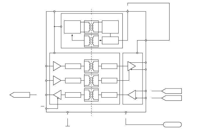
6.1 Interface Circuits
6.1.1 Sensor Data Input Port
The sensor data input port schematic is shown in Figure 27.
Figure 27 Input Port Schematic
A logical low input is defined as: A-B < -0.2V.
A logical high input is defined as: A-B > +0.2V.
6.1.2 Bi-directional Data Ports
The input circuitry of the bi-directional data ports is identical to the input circuit-
ry for the sensor data input ports described in the preceding section. The out-
put circuitry consists of a differential line driver IC (Analog Devices
ADM2587E) and is shown in Figure 28.
Oscillator Rectier
Regulator
Decode
Digital isolation Transceiver
VISOIN
Encode
DecodeEncode
Decode
ADM2587E
RX_A
TxD
Vcc
DE
Y
Z
A
B
RxD
RE
RX
To UART
Data input port
Isolation Barrier
RX_B
RX_COM
Encode
VISOOUT
DC to DC Converter
GND1GND2
Technical Information
Page 62
Figure 28 Data Output Port Schematic
6.2 Output Drive Capability of Bi-directional Ports
Bi-directional ports can supply an output current of up to 30mA. The output
voltages are 0 (low) and 3.3V (high). Effective load resistance should be in
excess of 100 Ohms.
6.3 DGNSS Port
The DGNSS correction port is intended for connection to a Beacon Receiver.
The port has the same physical characteristics as the bi-directional data ports
as described in the preceding sections. If connection of a beacon receiver is
not required this port can be re-configured as an additional bi-directional port
to IEC61162-2.
Oscillator Rectier
Regulator
Decode
Digital isolation Transceiver
VISOIN
Encode
DecodeEncode
Decode
ADM2587E
RX_A
TxD
Vcc
DE
Y
Z
A
B
RxD
RE
RX
TX
From UART Data output port
Isolation Barrier
RX_B
TX_A
TX_B
RX_COM
Encode
VISOOUT
DC to DC Converter
GND1GND2
Each bi-directional data port is isolated from the other bi-
directional data ports and from the transceiver’s internal
power supply.
!

Technical Information
Page 63
6.4 Input Data Sentence Formats
All data input is via IEC61162 / NMEA 0183 sentences. For details of the sen-
tences and their checksums please refer to IEC61162-1.
6.5 AIS Transceiver Overall Dimensions
Figure 29 Transceiver Dimensions
165 mm111 mm
196 mm
143 mm
152 mm
130 mm
79 mm
49 mm
Technical Information
Page 64
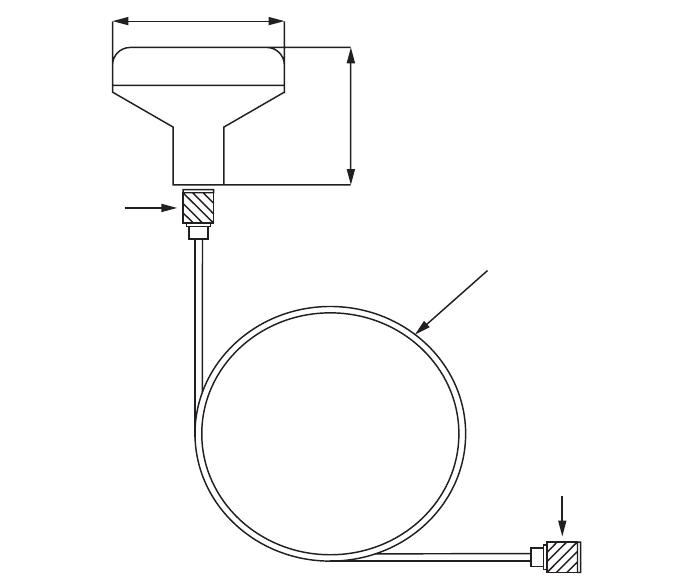
6.6 GNSS Antenna Drawing
Figure 30 GNSS Antenna
* The dimensions of the supplied antenna may vary from those shown here.
6.7 Transmission Intervals
The IEC61162 sentences are in general output in response to a specific event,
such as initiation of a binary message via the user interface. Certain messages
are output over the ports at regular transmission intervals. Table 6 lists each
sentence type and the transmission interval.
68mm
75mm
TNC (male)
TNC (male)
10m RG58 cable

Technical Information
Page 65
Table 6 IEC61162 Transmission Interval for Periodic Sentences
Output
Sentence
Type
Transmission Interval Comments
VDO Once a second Own vessel VDL reports. When a
report is not generated by the
transceiver a ‘dummy’ VDO is
generated in its place.
ALR (inac-
tive)
Once a minute If no alarms are active, a single
empty ALR sentence is output
ALR
(active)
Once every thirty sec-
onds
If any alarms are active, an ALR
sentence is output for each active
alarm.
ABK, ACA,
LR1, LR2,
LR3, LRF,
LRI, TXT,
VDM
Only transmitted when
specifically initiated by
an external event

Technical Information
Page 66
6.8 Interface Sentences
The IEC61162 sentences accepted by and output by the transceiver serial
data ports are listed in Table 7.
Table 7 IEC61162 Sentences Input and Output
Data Port Input Sentences Output Sentences
Sensor 1
Sensor 2
Sensor 3
DTM, GBS, GGA, GLL,
GNS, HDT, RMC, ROT,
VBW, VTG, THS
N/A
External
display
Pilot
Long range
ABM, ACA, ACK, AIR,
BBM, DTM, GBS, GGA,
GLL, GNS, HDT, LRF,
LRI, RMC, ROT, SSD,
VBW, VSD, VTG, EPV,
SPW, THS
ABK, ACA, ALR, LR1,
LR2, LR3, LRF, LRI,
TXT, VDM, VDO, TRL,
VER
DGPS RTCM SC-104 binary
format

Technical Information
Page 67
6.9 Unused Fields
Unused fields in the above sentences are listed in Table 8 below. All fields of
other input and output sentences that are not in this table are used..
Sentence Unused Fields Description
AIR 9
10
11
12
Channel of Interrogation
Message ID 1.1 Station 1 reply slot
Message ID 1.2 Station 1 reply slot
Message ID 2.1 Station 2 reply slot
DTM 2
3
5
7
Local datum subdivision code
Lat offset, min, N/S
Longitude offset, min, E/W
Altitude offset, (meter)
GBS 4
5
6
7
8
Expected error in altitude
ID of most likely failed satellite
Probability of missed detection for
most likely failed satellite
Estimate of bias on most likely failed
satellite
Standard deviation of bias estimate
GGA 5
6
7
8
9
10
11
12
No. of satellites in use, 00-12
Horizontal dilution of precision
Antenna altitude above/below mean
sea level (geoid)
Units of antenna altitude, m -
Geoidal separation
Units of geoidal separation, m
Age of diff. GPS data
Differential reference station ID
0000-1023
GNS 5
6
7
8
9
10
Number of satellites in use, 00-99
Horizontal dilution of precision
Antenna altitude, m, above mean-
sea-level
Geoidal separation, m
Age of differential data
Differential reference station ID

Technical Information
Page 68
Table 8 Unused Fields
6.10 Proprietary Sentences
The transceiver outputs no proprietary sentences in normal operation.
6.11 Priority of Sensor Ports
The transceiver automatically assigns a priority scheme to connected
sensors. Data from the highest priority sensor will always be used. Sensor
input priority is for:
●Position
●COG+SOG
●Heading
●Rate-of-Turn
The sensor input ports have a priority order as shown in Table 9
RMC 7
8
Date: dd/mm/yy
Magnetic variation, degrees, E/W
VBW 1
2
3
7
8
9
10
Longitudinal water speed, knots
Transverse water speed, knots
Status: water speed
Stern transverse water speed, knots
Status: stern water speed
Stern transverse ground speed
Status: stern ground speed
VTG 2 Course over ground, degrees mag-
netic
Port Priority (1 = highest)
Sensor 1 1
Sensor 2 2
Sensor 3 3
Sentence Unused Fields Description

Technical Information
Page 69
Table 9 Port Priority Order
6.11.1 Position Priority Scheme
Position information is taken from the highest priority source reporting DTM
with WGS84 or datum override and RMC. If no RMC sentences are available,
position shall be taken from the highest priority source reporting DTM with
WGS84 or datum override and any one of:
• GGA
•GNS
•GLL
The following sentences are only processed only if they are from the currently
selected position source:
•RMC
• GGA
•GNS
•GLL
•GBS
•GRS
•GSA
•GSV
•GFA
When no position has been received on the selected port for 30 seconds, the
port is deselected as a position source, and a new source selected as de-
scribed above.
6.11.2 Course and Speed Priority Scheme
COG and SOG are taken from the highest priority source reporting any one of:
• RMC (with DTM=WGS84 or datum override)
•VTG
•VBW
VTG and VBW are only processed if they are from the currently selected COG
& SOG source. When no COG+SOG has been received on the selected port
External Display 4
Pilot 5
Long Range 6
Port Priority (1 = highest)
Technical Information
Page 70
for 30 seconds, the port shall be deselected as a COG+SOG source, and a
new source selected as described above.
6.11.3 Heading Priority Scheme
Heading shall be taken from the highest priority sensor reporting any one of:
•HDT
•THS
HDT and THS are only processed if they are from the currently selected Head-
ing source. When no heading has been received on the selected port for 30
seconds, the port shall be deselected as a heading source, and a new source
selected as described above
6.11.4 Rate of Turn Priority Scheme
Rate-of-Turn shall be taken from the highest priority sensor reporting ROT.
ROT shall only be processed if they are from the currently selected Rate-of-
Turn source. When no Rate-of-Turn has been received on the selected port
for 30 seconds, the port shall be deselected as a Rate-of-Turn source, and a
new source selected as described above.
6.12 Compatibility Mode
Some devices require the use of Compatibility Mode for correct operation.
When operating in the standard mode the fix quality flag indicates the type of
GNSS position that is being reported. In compatibility mode, the fix quality re-
ported will either be No GNSS or GNSS.
On the ‘Interfaces’ screen, under the configuration menu for each sensor port
there is an On/Off toggle which can be set if Compatibility Mode is required for
that port.
6.13 Message 24 Content
The Unit Serial Number transmitted in AIS Message 24B, in response to a
Message 15 request, is encoded as follows (note that these characters repre-
sent individual bits in the data):
wwww wwyy yxxx xxxx xxxx
w = week (0 - 63)
y = years since 2014 (0 - 7)
x = incrementing number (0 - 2047)

Technical Information
Page 71
6.14 NMEA 2000 PGN List
The PGN’s listed in Table 10 are supported by the transceiver. There are no
unused fields.
PGN
(Dec.)
PGN
(Hex)
Title in NMEA Data-
base Usage NMEA 0183
059392 0E800 ISO Acknowledgment out
059904 0EA00 ISO Request in, out
060928 0EE00 ISO Address Claim in, out
065240 0FED8 ISO Commanded
Address
in, out
126208 1ED00 Group Function in, out
126992 1F010 System Time out
126993 1F011 Heartbeat out
126996 1F014 Product Information in, out
127520 1F112 Vessel Heading in
127251 1F113 Rate of Turn in
129025 1F801 GNSS Position (Rapid
Update)
out RMC
129026 1F802 GNSS Direction Data in, out RMC
129029 1F805 GNSS Position Data in, out
129038 1F80E AIS Class A Position
Report
out VDO, VDM
129039 1F80F AIS Class B Position
Report
out VDO, VDM
129040 1F810 AIS Class B Extended
Position Report
out
129041 1F811 AIS AtoN Report out VDO, VDM
129545 1FA09 GNSS RAIM in

Technical Information
Page 72
Table 10 PGN Lists
129793 1FB01 AIS UTC and Date
Report
out VDO, VDM
129794 1FB02 AIS Class A Static and
Voyage Related Data
out VDO, VDM
129795 1FB03 AIS Addressed Binary
Message
out
129796 1FB04 AIS Acknowledge out
129797 1FB05 AIS Binary Broadcast
Message
out
129798 1FB06 AIS SAR Aircraft Posi-
tion Report
out VDO, VDM
129801 1FB09 AIS Addressed SRM out
129802 1FB0A AIS Safety Broadcast
Binary Message
out VDO, VDM
129809 1FB11 AIS Class B CS Static
Data Report Part A
out VDO, VDM
129810 1FB12 AIS Class B CS Static
Data Report Part B
out VDO, VDM
PGN
(Dec.)
PGN
(Hex)
Title in NMEA Data-
base Usage NMEA 0183

Technical Information
Page 73
6.15 Troubleshooting
Issues Possible cause and remedy
No data is being
received by a connected
chart plotter
• Check that the power supply is connected
correctly.
• Check that the power supply is a 12V or
24V supply.
• Check that the connections to the chart
plotter are correct.
The screen is not illumi-
nated
• Check that the power supply is connected
correctly.
• Check that the power supply is a 12V or
24V supply.
The RED ‘Alarm’ icon is
illuminated
• The unit may not have a valid MMSI.
Check that the AIS transceiver is correctly
configured with a valid MSSI.
• The VHF antenna may be faulty. Please
check the connection to the VHF antenna
and that the VHF antenna is not damaged.
The alarm icon may illuminate briefly if the
power supply is interrupted or the VHF
antenna characteristics are briefly affected.
• No GPS position fix can be obtained.
Please check the transceiver is located
where the internal GPS antenna has a
clear sky view or that an external GPS
antenna is properly connected and
installed. Review the GPS signal strength
graph in ‘System settings / GNSS Source’.
• The power supply is outside the allowable
range. Check that the power supply is
within the range 9.6V to 31.2V
• If none of the above correct the error condi-
tion please contact your dealer for advice.
• Check for error and alarm messages in the
‘Alarms’ menu.

Technical Information
Page 74
Table 11 Troubleshooting
If the guidance given in the table above does not rectify the problem you are
experiencing, please contact your dealer for further assistance.
My MMSI is being
received by other ves-
sels but my vessel name
is not shown on their
chart plotter or PC.
• Some older AIS devices and chart plotters
do not process the specific class B mes-
sage which provides the vessel name
(message 24). This is not a fault of your
AIS transceiver. software upgrades are
available for may older chart plotters which
will correct this issue. The other vessel
should update its AIS unit and/or chart plot-
ting software to receive AIS message 24.
Junction Box Accessory
Page 75
7 Junction Box Accessory
7.1 What’s in the Box
The items below are included in the junction box purchase. If any of these
items are missing, please contact your dealer.
Figure 31 Junction Box - What’s in the Box
7.2 Installation
The junction box should be mounted within 2m of the AIS transceiver, to en-
sure that the cable can be run without compromising its performance.
1. Connect the two extension cables between the transceiver and the
junction box.
2. Remove the lid of the junction box using a 3mm Allen Key. Route your
accessory cables through the waterproof cable glands and find the
appropriate terminal blocks to fix them to.
3. Use the connector diagrams shown in Figure 12 and Figure 14 as your
guide.
4. Secure the earth/screen/shield of the accessory cables to the metallic
strips of the junction box or to the appropriate connection on the termi-
nal block.
5. By default, the 120 Ohm jumper connectors should all be fitted to termi-
nate any unused ports. If a port requires no termination, then that port’s
jumper can be removed.
6. Secure the accessory cables within the junction box with cable ties.
7. Refit the lid securely to ensure waterproofing.
Quick Start
Guide
18 way
extension cable
14 way
extension cable
Junction
Box
Self-Tapping Screws
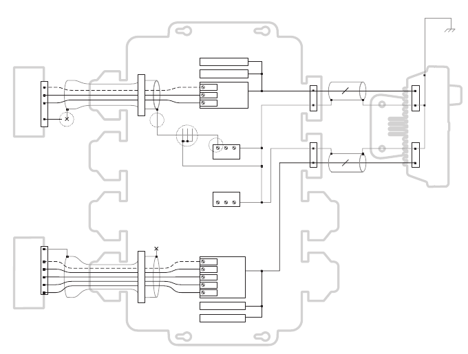
Junction Box Accessory
Page 76
7.3 Connecting External Equipment
Figure 32 shows an example of how external equipment could be connected
through the junction box accessory.
Figure 32 Connecting the External Equipment
When connecting external equipment the following procedures should be ob-
served.
• The common line should be connected to the sensor port if one is avail-
able.
• The shield in the cable used to connect the external equipment should be
connected at one end only, Refer to the manufacturers documentation
regarding cable construction.
• The chassis connection can be made with EITHER a drain wire OR
directly to the cable shield using exposed wire links on the junction box
printed circuit board, depending on the cable construction.
COM
Rx A
Rx B
COM
Rx A
Rx B
Tx A
Tx B
COM
Shield
Tx A
Tx B
Rx A
Rx B
COM
Shield
Tx A
Tx B
Chassis
Chassis
Sensor
(eg. external GNSS)
Junction box
AIS transceiver
Chart plotter
Sensor port 3
Sensor port 2
Sensor port 1
(Orange, Purple,
Green wires)
External
display port
Pilot port
LR/DGPS port
Earth stud
connection
13
17

Junction Box Accessory
Page 77
7.4 Technical Information
7.4.1 Physical
7.4.2 Environmental
7.4.3 Data Connector Information
Junction Box
Dimensions
235mm x 69mm x 233mm (WxHxD)
Junction Box
Weight
0.65kg
Operating Temperature
Range -15°C to +55°C
Maximum Operating
Humidity 90% at +40°C, non-condensing
Water Ingress Rating IPx6
18 way data
connector
Chogori
23018525-04-RC
Mating Half Chogori
23018221-01
14 way data
connector
Chogori
23014525-05-RC
Mating Half Chogori
23014221-01
Junction Box Accessory
Page 78

Technical Specification
Page 79
8 Technical Specification
8.1 Applicable Equipment Standards
IEC61993-2
Ed. 2.0
2012-10
Class A shipborne equipment of the universal auto-
matic identification system (AIS) – Operational and
performance requirements, methods of test and
required test results
IEC60945
4th Ed.
2002-08
Maritime navigation and radio communication equip-
ment and systems –
General requirements – Methods of testing and
required test results
IEC61162-1
Ed. 4.0
2010-11
Maritime navigation and radio communication equip-
ment and systems –
Digital interfaces - Single talker and multiple listeners
IEC61162-2
Ed. 1.0
1998-09
Maritime navigation and radio communication equip-
ment and systems –
Digital interfaces - Single talker and multiple listen-
ers, high speed transmission
IEC61162-3
2008+A2:2014
Maritime navigation and radio communication equip-
ment and systems -
Digital interfaces - Part 3: Serial data instrument net-
work.
ITU-R M.1371-5
02/2014
Technical characteristics for an automatic identifica-
tion system using time division multiple access in the
VHF maritime mobile band
IEC61108-1
2nd Ed.
2003-07
Global Navigation Satellite Systems (GNSS) –
Part 1: Global positioning system (GPS) - Receiver
equipment - Performance standards, methods of
testing and required test results
IEC6118-02
1st Ed.
1998-06
Global navigation satellite systems (GNSS) - Part 2:
Global navigation satellite system (GLONASS) -
Receiver equipment - Performance standards, meth-
ods of testing and required test results
CCNR VTT
Ed. 1.2
23.4.2013
Central commission for Navigation on the Rhine,
Inland AIS Equipment
- Vessel Tracking and Tracing Standard for Inland
Navigation

Technical Specification
Page 80
8.2 Product Category
8.3 Physical
8.4 Environmental
8.5 Electrical
Product Category This product is categorized as ‘protected’ in accor-
dance with the definitions provided in IEC 60945
Transceiver
Dimensions
152mm x 165mm x 111mm (WxHxD), see Figure 29
for drawing)
Transceiver
Weight
1.5kg
Compass Safe
Distance
0.5m (Transceiver)
Operating Temperature
Range -15°C to +55°C
Maximum Operating
Humidity 90% at +40°C, non-condensing
Water Ingress Rating IPx6, IPx7
Supply Voltage 12 to 24V DC (absolute min 10.8V, absolute
max 31.2 V)
Power Consumption < 12W
Current Consumption
@12 VDC Supply
0.9A typical, 6.0A peak
Current consumption
@24 VDC supply
0.5A typical, 4.0A peak

Technical Specification
Page 81
8.6 Display and User Interface
8.7 Internal GNSS
Display 800 x 480 pixel colour LCD with adjustable backlight
Luminance 500cd/m2 max, 75cd/m2 default
Recommended
Viewing Distance
45cm
Keypad Five function keys and three menu keys with adjust-
able backlight
Rotary Control Encoder with push function
Speaker 600mW@750Hz 11mm x 15mm
Receiver Chan-
nels
32 channels GPS and GLONASS operating modes
Time to First Fix Typically 26 seconds
Frequency L1 GPS band, 1575.42MHz and L1 GLONASS band
1597.1 - 1609.5MHz
Accuracy 2.5m CEP / 5.0m SEP without differential correction
2.0m CEP / 3.0m SEP with SBAS or RTCM DGPS
correction
Antenna Require-
ment
Active antenna (5V bias) with gain >15dB

Technical Specification
Page 82
8.8 TDMA Transmitter
8.9 TDMA receiver
8.10 DSC Receiver
Frequency Range 156.025MHz to 162.025MHz
Channel Bandwidth 25kHz
Output Power 1W or 12.5W (automatic selection)
Data Transmission Rate 9600 bits/s
Modulation Mode 25kHz GMSK
Number of Receivers 3
Frequency Range 156.025MHz to 162.025MHz
Channel Bandwidth 25kHz
Sensitivity <-107dBm for 20% PER
Modulation Mode 25kHz GMSK
Adjacent Channel Selectivity 70dB
Spurious Response Rejection 70dB
Number of Receivers 1
Frequency 156.525MHz (Channel 70)
Channel Bandwidth 25kHz
Sensitivity -107dBm @ BER <10-2
Modulation mode 25kHz AFSK
Adjacent channel selectivity 70dB
Spurious response rejection 70dB

Technical Specification
Page 83
8.11 RF Connections
8.12 Data interface
VHF Antenna Connection SO-239 / UHF
VHF Port Impedance 50 Ohms
GNSS Antenna Connections TNC female
GNSS Port Impedance 50 Ohms
Sensor Data Input Ports
Number of Ports 3
Standard IEC61162-1 / -2
Baud Rate 4800 baud or 38400 baud
Port Impedance 54K Ohms
Bidirectional Data Ports (including pilot port)
Number of Ports 3
Standard IEC61162-1 / -2
Baud Rate 4800 or 38400 baud
Port Impedance 54K Ohm
Differential Correction Port
Standard ITU 823-2 / RTCM SC-104
Baud Rate 4800 baud or 38400 baud
Port Impedance 54K Ohms
Blue Sign Port
Port Impedance 10K Ohms

Technical Specification
Page 84
8.13 Power and Data Connector Information
8.14 Open Source Licences
This product contains open source software. For details please see the ‘Sys-
tem information’ screen.
8.15 Product Versions
At delivery, the product contains the following software and hardware ver-
sions:
MKD Software: 110400.01.09
MKD Firmware: 110400.01.09
Modem Software: 110200.01.02
MKD Hardware: 1
Modem Hardware:1
The ‘System Information’ screen will display the currently installed software
and hardware versions on the transceiver. If this differs from that stated here,
please check Online for an updated manual.
Silent Mode Port
Port Impedance 10K Ohms
NMEA 2000 Port:
Load Equivalency
Number (LEN)
1
Power Con-
nector
Chogori
22002525-04-RC
Mating Half Chogori
22002221-01
18 way Data
Connector
Chogori
23018525-04-RC
Mating Half Chogori
23018221-01
14 way Data
Connector
Chogori
23014525-05-RC
Mating Half Chogori
23014221-01

Installation Record
Page 85
9 Installation Record
The following installation record should be completed and retained on
board the vessel once the AIS transceiver has been installed and com-
missioned.
9.1 Vessel Details
Vessel Name
Flag State
IMO Number MMSI Number
Owner Radio Call
Sign
Type of Vessel Gross Regis-
tered Tonnage
Length (m) Beam (m)
AIS Transceiver Serial Number
Installation Password
Radio Software Version Number
MKD Software Version Number
External GNSS Antenna Location (all dimensions in meters, refer to
diagram below
A= B= C= D=
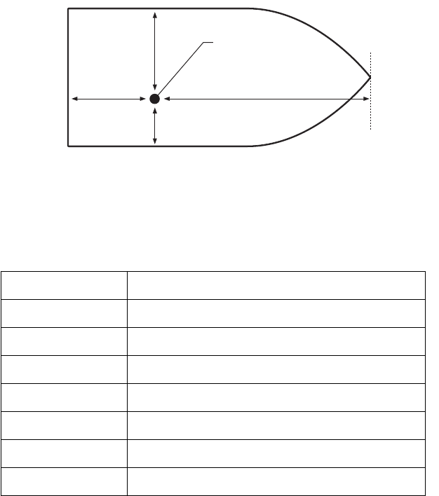
Installation Record
Page 86
Figure 33 GNSS Antenna Position
Connected equipment type (where applicable note equipment and AIS
data port in each case.
The following drawings should be provided and attached to this installa-
tion record.
• Antenna layout for VHF and GNSS antennas
• AIS arrangement drawing
• Block diagram showing interconnection of equipment
(D)GPS Receiver
Gyro Compass
ROT Indication
Speed Log
ECDIS
Radar
Other Equipment
Power Supply
Ref A
Antenna
Ref A + Ref B = Length in metres Ref C + Ref D = Beam in metres
Ref B
Stern Bow
Ref C
Ref D

Installation Record
Page 87
Maintenance Record
Installer Detail
Modification
record number
Details (enter details of modifications to the
transceiver including software updates)
1
2
3
4
5
6
7
8
9
10
Installed by
(name)
Installation com-
pany name
Date of installa-
tion
Vessel location
at installation
Signature
Installation Record
Page 88

201-0625:6
Manufacturer’s Code: 427
NMEA 2000 Product Code: xxxxx