ST Electronics AP96-US K-Band Miniature Microwave Doppler Transceiver Module User Manual AP96 v101
ST Electronics (Satcom & Sensor Systems) Pte Ltd K-Band Miniature Microwave Doppler Transceiver Module AP96 v101
User Manual
1 of 7
MSAN
-
00
9
K-Band Miniature Doppler Transceiver Module
Application Note
V1
.
0
0
ST Electronics (Sa
tcom & Sensor Systems) Pte Ltd
1 Ang Mo Kio Electronics Park Road, #06-02, ST Engineering Hub, Singapore 567710
Tel: (65) 6521 7888 Fax: (65) 6521 7801 Email: info@agilsense.com
Website: www.agilsense.com ( Regn. No.: 199103901W )
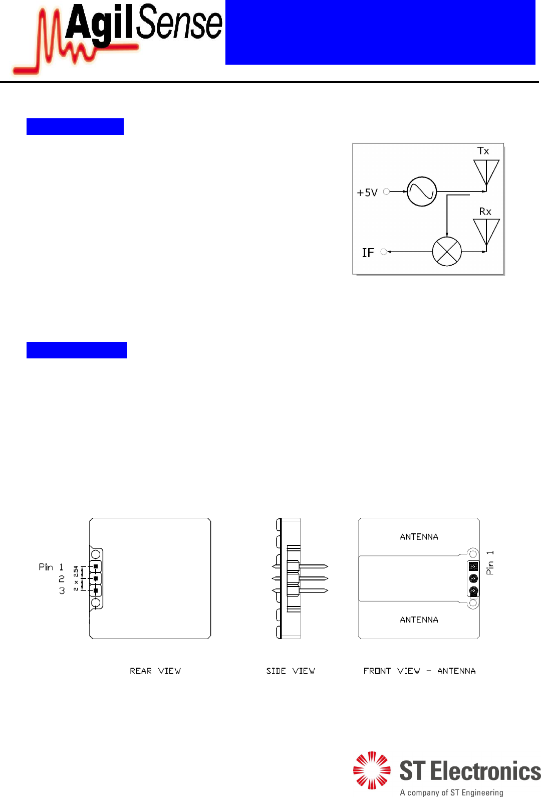
Figure 1: Block Diagram
1. Introduction
2. User Interface
A 3-way 2.54mm pin header is used for user interface. The pin header (shown in figure 2 below)
connects the terminals (+Vs, IF, GND) to the amplifier circuits. Any mounting methods deemed suitable
may be used, but the mounting parts should not touch the +Vs and IF lines and should not be too near to
the patch antennas.
Any pressure or stress to the chassis of the module must be avoided at all, as it may result in change of
module performance.
Figure 2: User interface pin definition: 1: Vin, 2: IF, 3: GND
AP96 series K-Band miniature microwave module is a
Doppler transceiver with built-in features such as low current
HEMT oscillator, single balance mixer and bi-static
microstrip patch antenna arrays. It is ideal for applications in
automatic access, security, lighting control and speed
measurement.
Its lightweight, miniature size and slim profile offer the
flexibility to OEM manufacturers in making trendy and slim
final products.
2 of 7
MSAN
-
00
9
K-Band Miniature Doppler Transceiver Module
Application Note
V1
.
0
0
ST Electronics (Sa
tcom & Sensor Systems) Pte Ltd
1 Ang Mo Kio Electronics Park Road, #06-02, ST Engineering Hub, Singapore 567710
Tel: (65) 6521 7888 Fax: (65) 6521 7801 Email: info@agilsense.com
Website: www.agilsense.com ( Regn. No.: 199103901W )
3. Power Supply
AP9 series module operates at +5 Vdc for Continious wave (CW) operation. There are also modules
(e.g. AP96-3) designed to operate at +3 Vdc.
The module can be powered by +Vs low duty cycle pulsed trains of up to 2KHz repetition frequency for
lower power consumption. Sample & Hold circuit at the IF output is required for pulse operation.
5. Transmit Frequency
The transmitting frequencies (ISM band) and EIRP (Effective Isotropic Radiated Power) of various
modules are factory-set and are not user-adjustable. Table 1 shows the EIRP and transmitting
frequencies of the various AP9 series modules.
Local radio communication authority regulates the use of transmitting devices. Though user license
may be exempted, type approval of equipment or other regulation compliance may be required.
CAUTION:
Plugging-in the module into an active power supply may not itself cause any damage, but any
accidental short to ground during this process may cause component damage in the module.
It is therefore recommended that power supply to be SWITCHED OFF first before connecting
the modules.
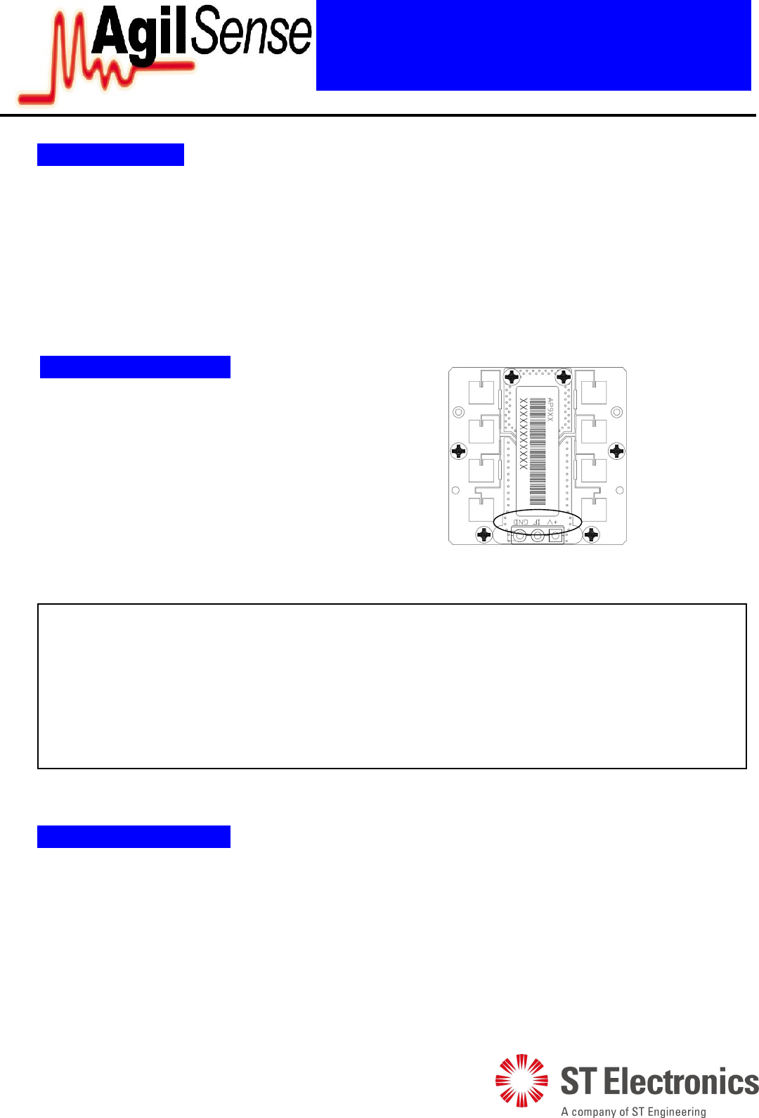
4. Before Powering Up
Connect the power supply, ground and
amplifier
circuitry to the designated terminals. Designation
of the connection terminals are printed on the
PCB as shown in diagram (right).
Figure 3: Terminals designation
3 of 7
MSAN
-
00
9
K-Band Miniature Doppler Transceiver Module
Application Note
V1
.
0
0
ST Electronics (Sa
tcom & Sensor Systems) Pte Ltd
1 Ang Mo Kio Electronics Park Road, #06-02, ST Engineering Hub, Singapore 567710
Tel: (65) 6521 7888 Fax: (65) 6521 7801 Email: info@agilsense.com
Website: www.agilsense.com ( Regn. No.: 199103901W )
Model EIRP (TYP.) Frequency Setting
AP96 15 dBm 24.000 - 24.250 GHz
AP96-US 15 dBm 24.075 – 24.175 GHz
AP96-3 15 dBm 24.000 - 24.250 GHz
Table 1: Transmitting frequency for AP9 series
Please refer to Annex 1 for more information on transmitting signal.
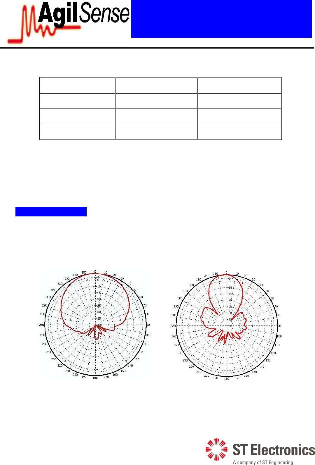
6. Radiation Pattern
The module is to be mounted with the antenna patches facing to the desired detection zone. The user
needs to choose the correct orientation of the module to obtain the desired coverage. The radiation
patterns of the antenna and their half power beam width (HPBW) are as shown in the diagram below.
Azimuth
Elevation
Figure 4: Beam pattern of AP9 series sensor modules

4 of 7
MSAN
-
00
9
K-Band Miniature Doppler Transceiver Module
Application Note
V1
.
0
0
ST Electronics (Sa
tcom & Sensor Systems) Pte Ltd
1 Ang Mo Kio Electronics Park Road, #06-02, ST Engineering Hub, Singapore 567710
Tel: (65) 6521 7888 Fax: (65) 6521 7801 Email: info@agilsense.com
Website: www.agilsense.com ( Regn. No.: 199103901W )
7. Output Signals
Doppler shift - Doppler signal appears at IF terminal when movement is detected. The magnitude of
the Doppler signal is proportional to the reflection of transmitted energy and is typically in the range of
microvolts (µV). A high-gain low-frequency amplifier is usually connected to the IF terminal in order
to amplify the Doppler shift to a processable level. The frequency of Doppler shift is proportional to
velocity of motion. Typical human walking generates Doppler shift below 100 Hz. Doppler frequency
can be calculated by Doppler equation in Annex 2.
The Received Signal Strength (RSS) is the voltage measured at the IF output, when the module is
subjected to a motion. Reflection of a human body is dependent on the size of the body, clothing,
apparels and other environmental factors. RSS measured for different human bodies may vary by as
much as 50%.
Circuit designer must take note of the typical Received Signal Strength (RSS) specified in technical
data sheet, when designing the amplifier. Sensitivity deviation between modules has to be considered
when setting amplifier gain or alarm threshold. On-production gain adjustment may be necessary if a
narrow window for triggering threshold is required.
Noise - The noise specified in the technical data sheet is the noise measured in an Anechoic chamber,
that shields the unit-under-test from external interference, as well as reflection from surfaces. Hence,
the figure is only presenting the noise generated by the internal circuit itself.
In actual applications, besides noise generated from internal electronic circuit, other noises may be
picked up from surrounding, or other part of the electronic circuit. Special attention has to be given to
the interference pick-up from fluorescent light, as the 100/120 Hz noise is closed to the Doppler
frequency generated by human movement. On and off switching of certain devices (relay, LED, motor,
etc.) may generate high magnitude of transient noise at the IF terminal. Careful PCB layout and time-
masking is necessary to prevent false triggering.
DC Level - DC level (0.01 to 0.2 Vdc) exists at the IF terminal and its polarity can be positive and
negative. Its magnitude may vary over temperature. AC coupling is recommended for IF terminal
connection.
8. Placing the module in enclosure
If AP9 series module needs to be housed in an enclosure, it is important to ensure that the performance
of the module is not significantly degraded by the presence of enclosure.
The recommended material for the enclosure is plastic (such as ABS), as microwave can penetrate
through the material without significant loss. For comparison purpose, a metal results in full reflection
while water results in high absorption of the microwave. It is therefore important not to use any metallic
material as the enclosure.
5 of 7
MSAN
-
00
9
K-Band Miniature Doppler Transceiver Module
Application Note
V1
.
0
0
ST Electronics (Sa
tcom & Sensor Systems) Pte Ltd
1 Ang Mo Kio Electronics Park Road, #06-02, ST Engineering Hub, Singapore 567710
Tel: (65) 6521 7888 Fax: (65) 6521 7801 Email: info@agilsense.com
Website: www.agilsense.com ( Regn. No.: 199103901W )
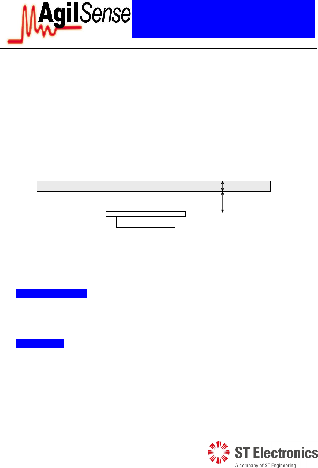
It is recommended that the cover placed in front of the module antenna is of flat panel, so that the
beamwidth of the antenna is not significantly distorted. The thickness of the cover, h1 and the spacing
between the antenna and the cover, h2 should be ideally half-wavelength of the microwave signal.
In this case, for AP9 series module whose transmission frequency is ~24GHz, the recommended h1 and
h2 are 3-4mm and 6mm.
A half wavelength of a 24 GHz in the air is about 6mm. However, the half wavelength of the signal in
other medium depends on the dielectric constant of the material. In the case of ABS which has a
dielectric constant of between 2.5 to 3.5, the half wavelength of the signal is 3 – 4 mm.
Figure 5: Recommended thickness and clearance for ABS placed in front of AP9 sensor
9. Radiation Safety
Microwave radiation from the module is well below established safety standards for general public
environment, like ANSI C95.1-1991 of USA and NRPB-G11 of United Kingdom.
10. Handling
The module has been fully tested to specifications. Upon opening, tighten or loosen the chassis will
cause performance deterioration.
The module is an electrostatic-sensitive device (ESD). Precautions must be observed for handling and
storage of the modules.
h
1
~ 3
-
4 mm
h2 ~ 6mm
ABS
AP9 unit

6 of 7
MSAN
-
00
9
K-Band Miniature Doppler Transceiver Module
Application Note
V1
.
0
0
ST Electronics (Sa
tcom & Sensor Systems) Pte Ltd
1 Ang Mo Kio Electronics Park Road, #06-02, ST Engineering Hub, Singapore 567710
Tel: (65) 6521 7888 Fax: (65) 6521 7801 Email: info@agilsense.com
Website: www.agilsense.com ( Regn. No.: 199103901W )
10. Product Support
Please contact our product support engineers in the factory for technical assistance whenever necessary.
Product Support (Microwave Sensors)
Tel: (65) 6521 7888
Fax: (65) 6521 7801
E-mail: info@agilsense.com
This device complies with part 15 of FCC Rules.
Operation is subject to the following two conditions: (1) This device may not cause harmful interference, and
(2) this device must accept any interference received, including interference that may cause undesired
operation.
Any changes or modifications to ST Electronics equipment not expressly approved by ST Electronics could
void the user authority to operate the equipment.
The system integrated the radio should have label indicated the FCC ID of approved Radio.
Such as putting a label on system as below: CONTAIN FCC ID: VECAP96-US
Warning : The radio does not allow to be installed and operated with other radio simultaneously when
integrated in host system.
Installed in such configuration may subject to additional FCC testing and equipment authorization.
7 of 7
MSAN
-
00
9
K-Band Miniature Doppler Transceiver Module
Application Note
V1
.
0
0
ST Electronics (Sa
tcom & Sensor Systems) Pte Ltd
1 Ang Mo Kio Electronics Park Road, #06-02, ST Engineering Hub, Singapore 567710
Tel: (65) 6521 7888 Fax: (65) 6521 7801 Email: info@agilsense.com
Website: www.agilsense.com ( Regn. No.: 199103901W )
Annex 1: Transmission of RF
1. Though same frequency is allocated in some countries, national regulations may specify different
EIRP, spurious emission or other requirements.
2. ETS EN300 440 is the recommended harmonized standard for European Community, member
country may adopt their own national regulation. The AP96 series transceivers meet the requirement
of EN300 440
3. The AP96-US model is designed to meet the FCC standard part 15.245 and is aimed for use in the
America.
4. The regulations are subjected to change from time to time, please contact appropriate authorities for
full and up-to-dated information.
5. Useful websites:
Agency Website
The Code of Federal Regulations, USA http://www.access.gpo.gov/cgi-
bin/cfrassemble.cgi?title=199847
The European Radiocommunication Office http://www.ero.dk/
The Radiocommunications Agency , UK http://www.radio.gov.uk/
Federal Communications Commission http://www.fcc.gov/
Annex 2: Doppler Equation
Where
Fd = Doppler frequency
V = Velocity of the target
Ft = Transmit frequency
c = Speed of light (3 X 10⁸m/sec)
= The angle between the target moving direction and the axis of the module.
If a target is moving straight toward or away from AP96 (Ft = 24.125 GHz). The formula is simplified
to:
Fd = 44.7V (Velocity in km/hour) or 71.9V (V in mile per hour)
Cos
c
F
2VF t
d