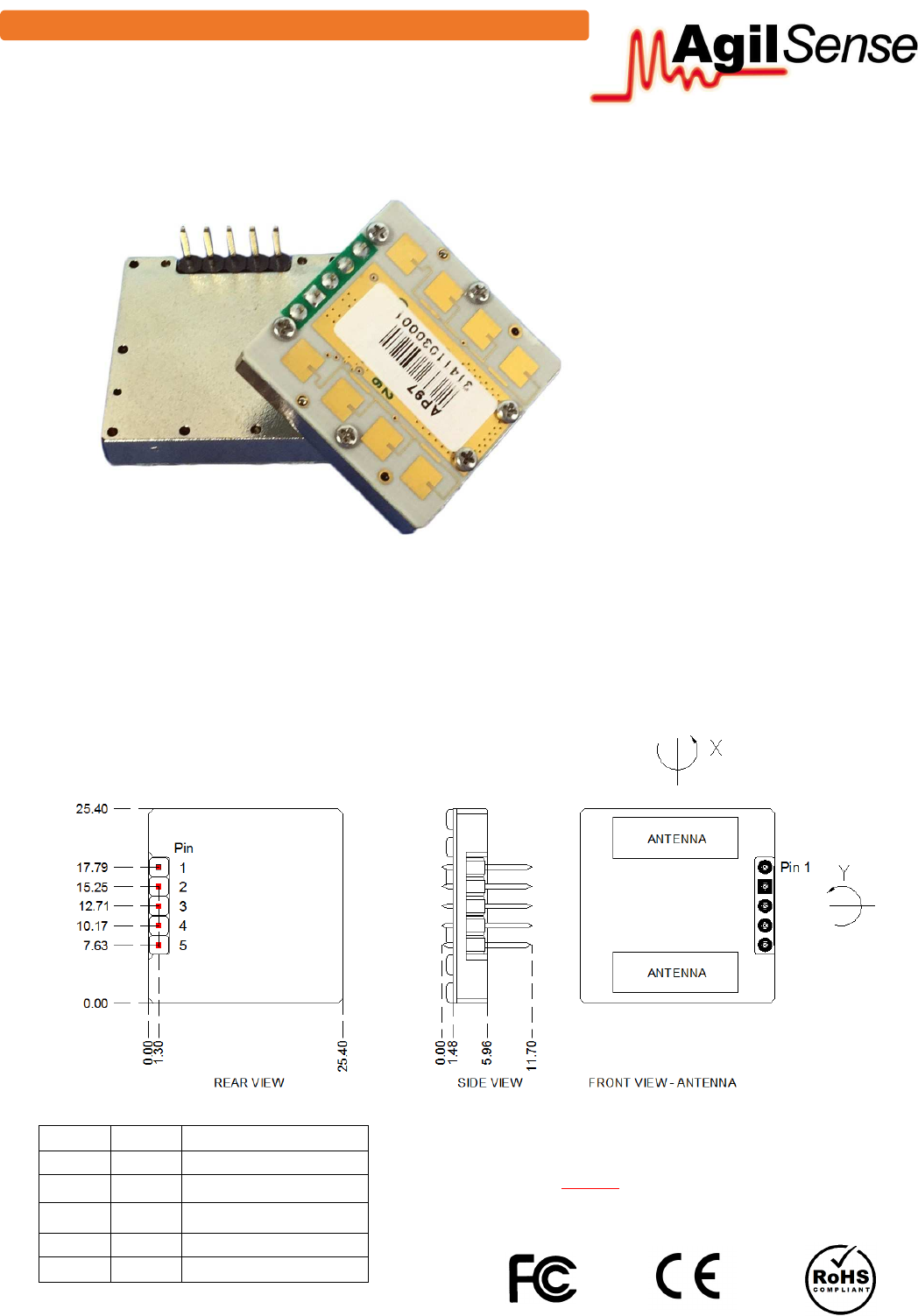
ST Electronics AP97 K-Band Miniature Microwave Doppler Transceiver Module User Manual Installation Instruction
ST Electronics (Satcom & Sensor Systems) Pte Ltd K-Band Miniature Microwave Doppler Transceiver Module Installation Instruction
VECAP97_User Manual_rev 2.pdf
sϮ͘Ϭϭ
)HDWXUHV
x0RWLRQGLUHFWLRQGLVFULPLQDWLRQ
x6PDOODQGIODWSURILOH
x/LJKWZHLJKW
x&:DQGSXOVHPRGHRSHUDWLRQ
x/RZFXUUHQWFRQVXPSWLRQ
$SSOLFDWLRQV
x0RWLRQGHWHFWLRQ
x/LJKWLQJFRQWURO
x6HFXULW\DODUP
x$XWRPDWLFGRRUFRQWURO
The AP97 series K-band miniature sensor is a Doppler transceiver with a HEMT oscillator, two sin-
gle balanced mixers and bi-static microstrip patch antenna arrays. It is suitable for applications
in automatic access, security, lighting control and speed measurement. It also has I-Q outputs
to discriminate motion direction.
Its lightweight, miniature size and slim profile offer the flexibility to OEMs in making trendy and
slim products.
$3
'XDO&KDQQHO0LQLDWXUH.-EDQG0LFURZDYH6HQVRU
All dimensions are in mm.
Note 1: Complies with EN 300 440.
Note 2: Complies with FCC Part 15.245.
Note 3: CAUTION: ELECTROSTATIC SENSITIVE DEVICE.
Observe precautions for handling and storage.
Pin Name Description
1 NC Not connected
2 +V Supply voltage, VIN
3 I Channel I
4 GND Ground
5 Q Channel Q
0RGXOH2XWOLQH
sϮ͘Ϭϭ
0
30
60
90
120
150
180
210
240
270
300
330
-40
-30
-20
-10
0
-40
-30
-20
-10
0
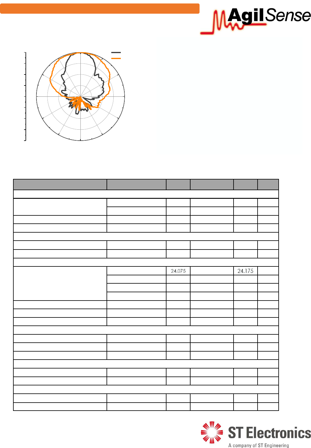
Normalized Radiation Pattern (dB)
X
Y
$QWHQQD%HDP3DWWHUQ
7HFKQLFDO6SHFLILFDWLRQV
Unless noted otherwise, the specifications are measured in CW mode, VIN = 5 VDC and 12k ohm
load at +25°C.
Parameter Remarks Min Typical Max Units
Operating Conditions
Supply voltage, VIN AP97,AP97-1,AP97-2 4.75 5 5.25 VDC
AP97-3 2.85 3 3.15 VDC
Current consumption 30 40 mA
Operating temperature -20 60 °C
Recommended Pulse Scheme
Pulse frequency Pulse mode 2 KHz
Duty cycle Pulse mode 2 %
Transmitter
Operating frequency AP97 24.000 24.125 24.250 GHz
AP97-1 24.075 24.125 24.175 GHz
AP97-2 24.150 24.200 24.250 GHz
AP97-3 24.000 24.125 24.250 GHz
Radiated power (EIRP) 15 dBm
Spurious emission -30 dBm
Frequency drift vs temperature -1 MHz/°C
Antenna
Antenna beam-width (3 dB) - X 80 °
Antenna beam-width (3 dB) - Y 32 °
Antenna sidelobe rejection 15 dB
Receiver
I&Q amplitude balance 0.5 3 dB
I&Q phase difference 70 90 110 °
Physical Properties
Dimensions 25.4×25.4×11.7 mm
Weight 3 g
67(OHFWURQLFV6DWFRP6HQVRU6\VWHPV3WH/WG
$QJ0R.LR(OHFWURQLFV3DUN5RDG-67(QJLQHHULQJ+XE6LQJDSRUH
7HO)D[
:HEVLWHZZZDJLOVHQVHFRP5HJQ1R:
%ORFN'LDJUDP

4 of 7
MSAN-00X
AP97 K-Band Miniature Doppler Transceiver Module
Application Note
V1.00
7. Placing the module in enclosure
When AP97 sensor module is housed in an enclosure, it is important to ensure that the performance of
the module is not significantly degraded by the presence of the enclosure.
A suitable material with both lower dielectric constant and lower loss tangent (that is ABS) is preferred.
Microwaves penetrate through plastic material without significant loss as long as it does not have direct
contact with the antenna patch surface. In comparison, metal results in full reflection while water results
in significant absorption of microwaves. Therefore it is important not to place any metallic material in
front of the antenna.
Ideally, surface of the enclosure in front of the antenna should be flat. Curved surface introduces beam
pattern distortion, both main beam and side-lobes.
It is also important for user to note that the selection of the enclosure thickness, and the spacing in
between from the antenna patch surface, is in relation to the wavelength of the microwave signal and the
dielectric constant of the enclosure material. For ABS material that has a dielectric constant of between
2.5 to 3.5, the recommended spacing is approximately 6mm, and the recommended thickness is between
3 to 4mm.
User is advised to fine-tune the spacing between the antenna and the enclosure in accordance to their
application for optimum performance as depicted in figure 5.
Figure 4: Optimizing thickness and clearance for ABS placed in front of AP97 sensor module.
3 ~ 4mm
ABS enclosure
Antenna side
6mm (requires fine-tuning)
AP97
unit