ST Engineering Telematics Wireless RSC-900 User Manual revised
Telematics Wireless Ltd. revised
UserManual.wiki
>
ST Engineering Telematics Wireless
>
RSC-900 User Manual
>
revised User manual
Contents
1.
2 pages
2.
revised manual
3.
revised User manual
revised User manual
Navigation menu
Upload a User Manual
Namespaces
Wiki Guide
HTML
PDF
Info
Views
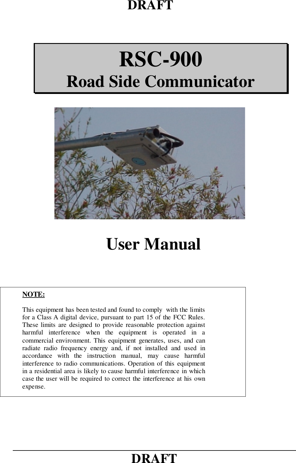
User Manual
Discussion / Help
Navigation