ST Engineering Telematics Wireless RSC-900 User Manual revised
Telematics Wireless Ltd. revised
Contents
- 1. 2 pages
- 2. revised manual
- 3. revised User manual
revised User manual
DRAFT
DRAFT
RSC-900
Road Side Communicator
User Manual
NOTE:
This equipment has been tested and found to comply with the limits
for a Class A digital device, pursuant to part 15 of the FCC Rules.
These limits are designed to provide reasonable protection against
harmful interference when the equipment is operated in a
commercial environment. This equipment generates, uses, and can
radiate radio frequency energy and, if not installed and used in
accordance with the instruction manual, may cause harmful
interference to radio communications. Operation of this equipment
in a residential area is likely to cause harmful interference in which
case the user will be required to correct the interference at his own
expense.
DRAFT
DRAFT
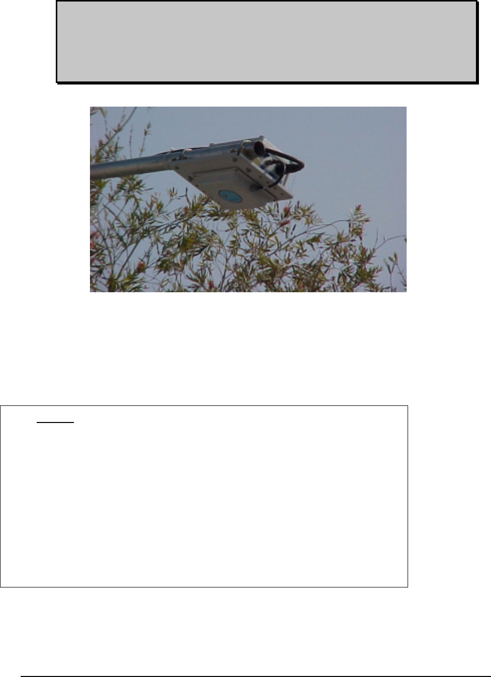
Installation & Operation instructions
The RSC has to be installed on a horizontal pipe above the center of a road lane.
The pipe has to be 1.5” up to 2” in diameter, and its length has to be sufficient to locate the RSC
over the center of the lane. (The width of a standard lane is about 3.6m). For longer pipes and for
areas with extreme winds it is important to add additional supports (still cables, etc.) to prevent
bending of the pipe.
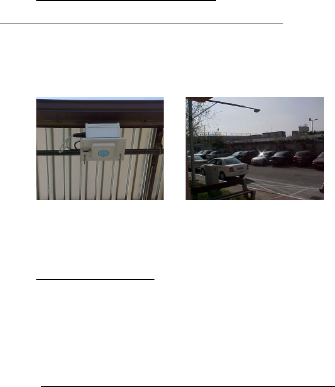
Installation of RSC on the pipe
The unit has two U stretchers that are connecting the main plate to the horizontal pipe.
The RSC-900 should be installed by professional installers ONLY authorized ONLY by
the local distributor – the “Operating Company”
DRAFT
DRAFT
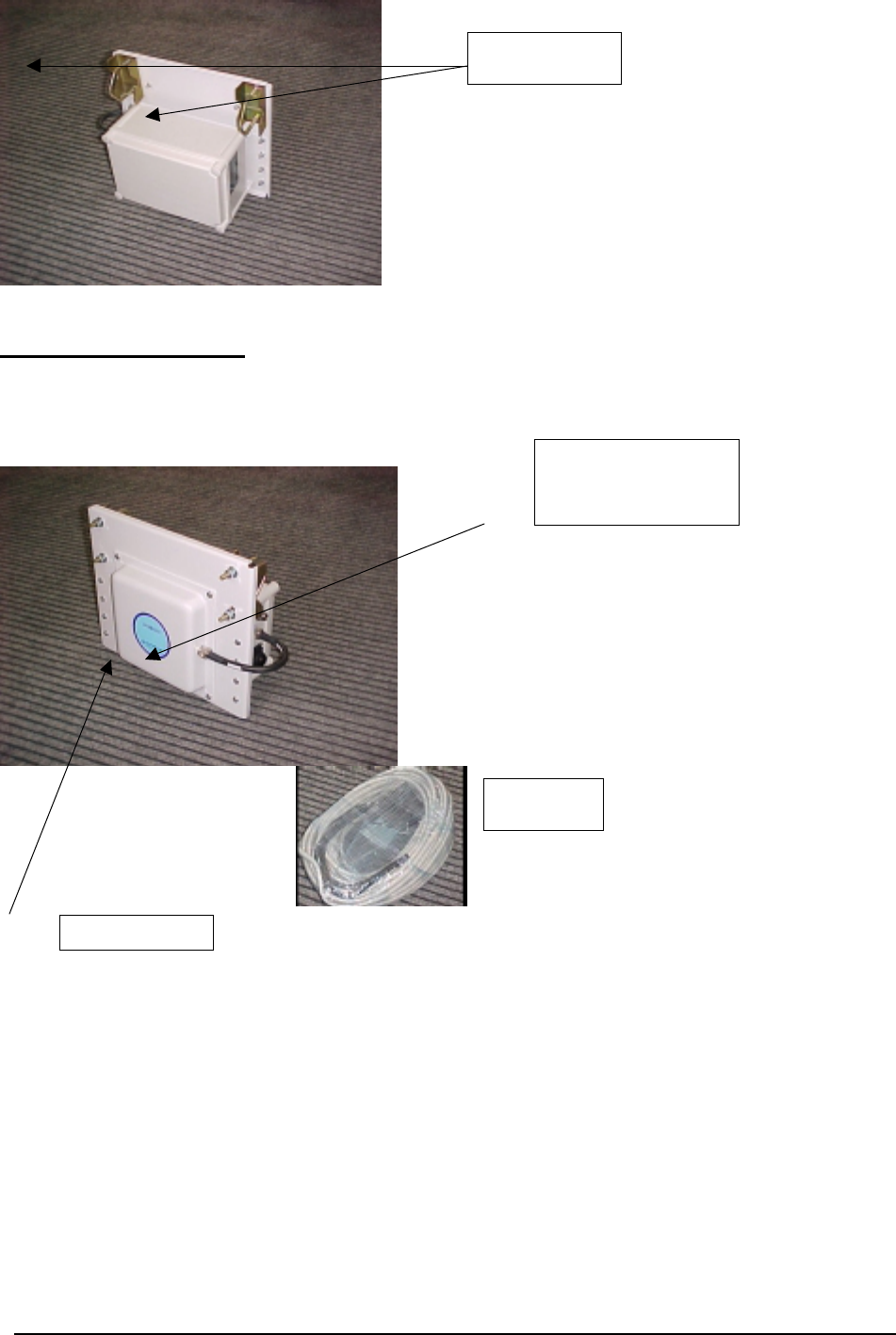
RSC cable connection
1. Connect the RSC Cable to RSC connector
The RSC-900 is delivered with a connected antenna.
Do not remove or change the antenna cable connections.
The use of any antenna other than the one being an integral part of the RSC-900 is expressly
forbidden in accordance with FCC rules CFR47 part 15.204.
Failure to do so may void the product warranty and may expose the end user or the service
provider to legal and financial liabilities.
U stretchers
RSC Connector
Antenna Cable
RSC cable

DRAFT
DRAFT
Power and communication connections
• Connect the main power (24 V) to the RSC cable to pins No 23/24 (+) and pins
No.21/22 (-)
• Connect the Communication line to the RSC cable to pins No: 11 (TXD), 10 (RXD),
and 21/22 (GND)
First operation test
1) Set up the basic initialization parameters:
• Communication mode
• DMRC (Data Management & Report Center) telephone Number
2) Call operating center of the “Operating Company” and give the RSC-900 serial number and
the local phone number for the RSC registration process in the DMRC.
3) Perform the communication test with the DMRC (Operating center) and the unit remote
initialization.
4) Perform Operational test.
Here we will add additional instructions according to the “Operating
Company” requests

DRAFT
DRAFT
We will be happy to assist you at operating support center
Tel:
Fax:
“Operating Company” Name Logo and address