ST Engineering Telematics Wireless T210A RF module for RF mesh network User Manual DCU2 E Installation Manual v1 1
Telematics Wireless Ltd. RF module for RF mesh network DCU2 E Installation Manual v1 1
Contents
- 1. Users Manual revised
- 2. Users Manual
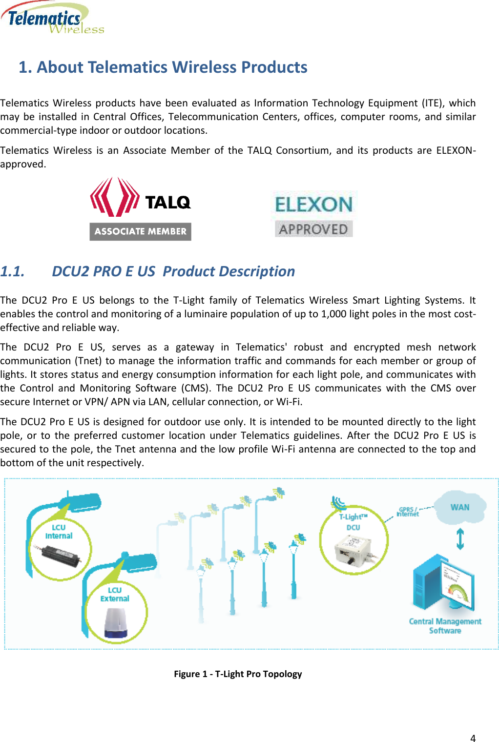
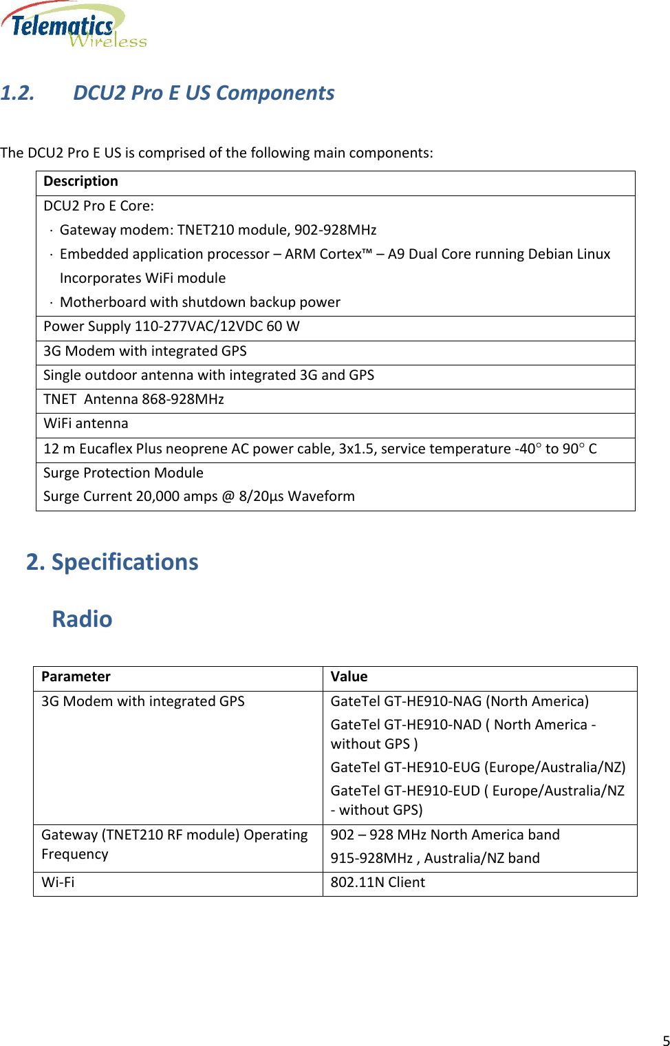
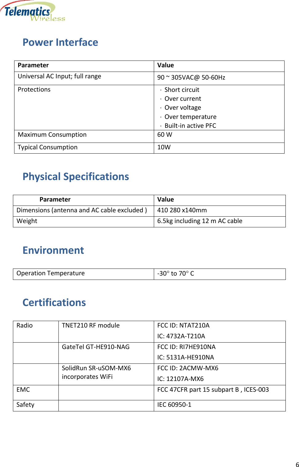
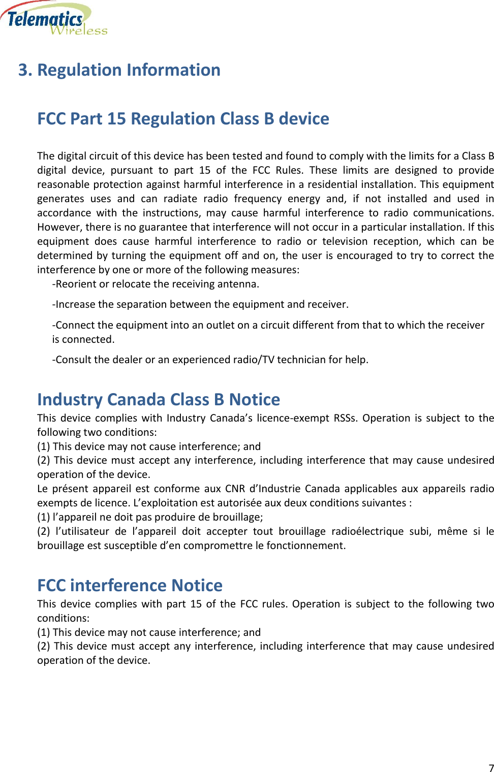
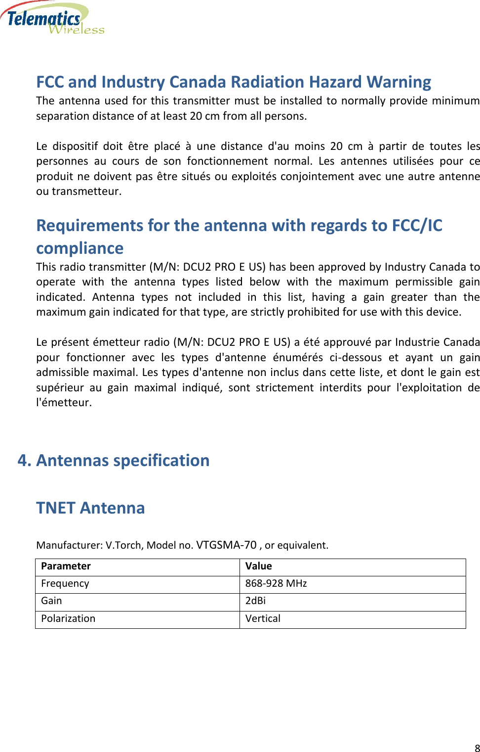
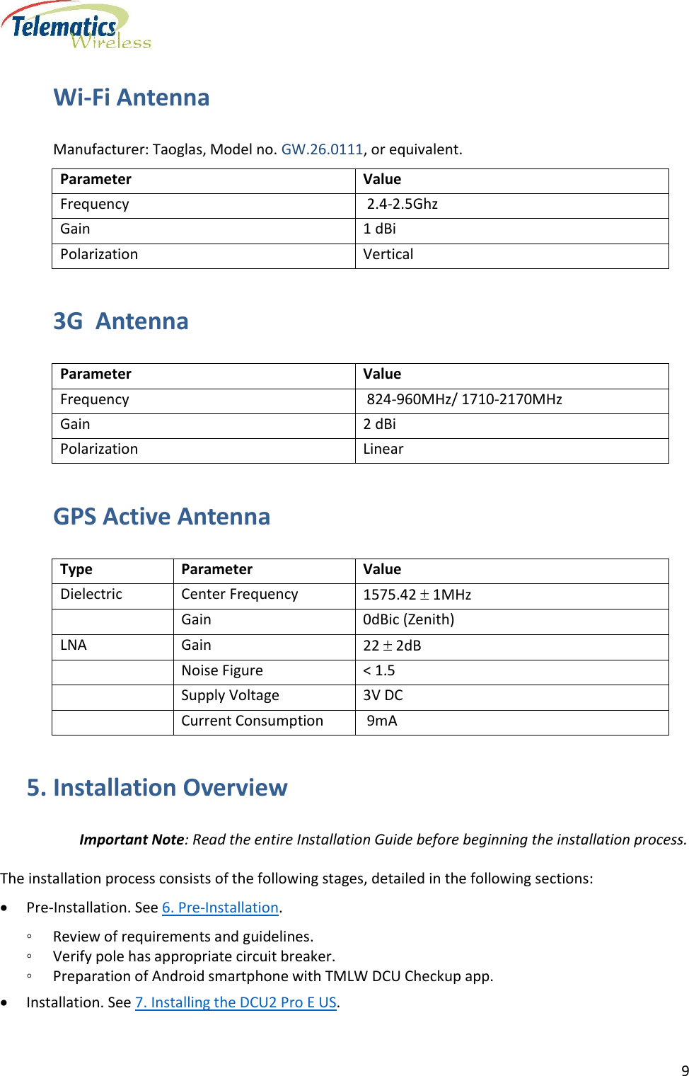
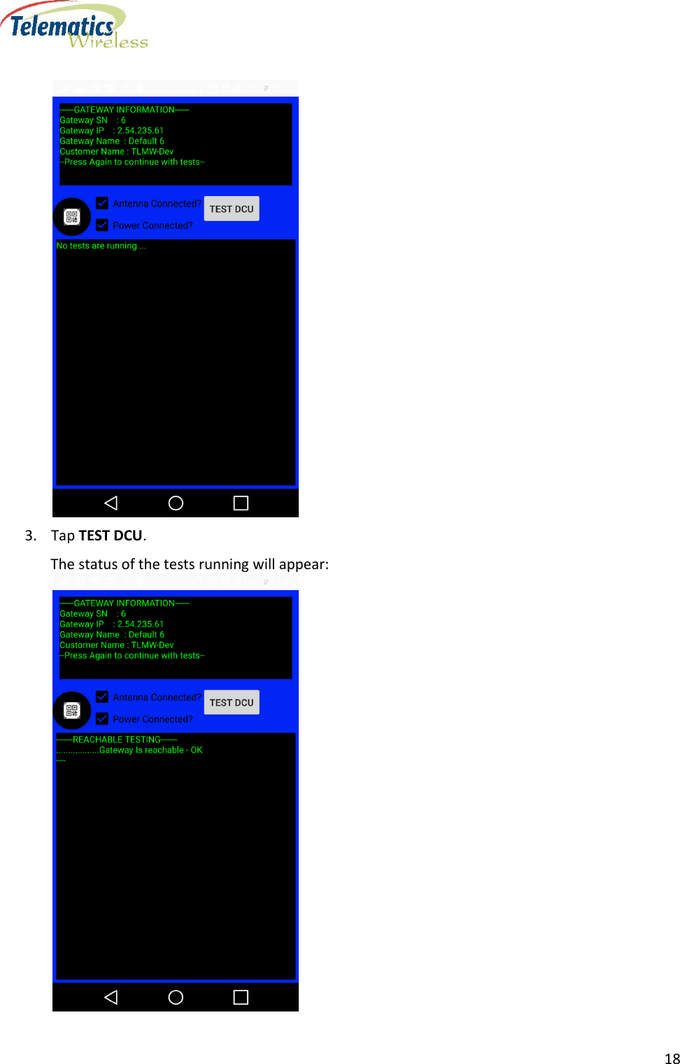
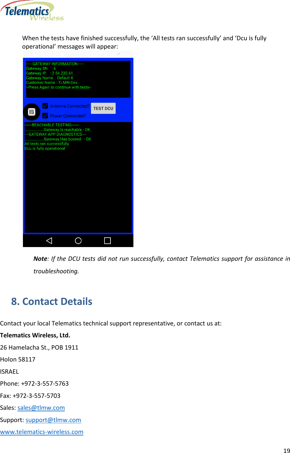
Users Manual