ST Engineering Telematics Wireless T210A RF module for RF mesh network User Manual DCU2 E Installation Manual v1 1
Telematics Wireless Ltd. RF module for RF mesh network DCU2 E Installation Manual v1 1
Contents
- 1. Users Manual revised
- 2. Users Manual
Users Manual

T-LightTM Data Communication Unit Pro Exterior
Model:DCU2 PRO E US
User Manual
Revision 1.02, June 21, 2016
Copyright © Telematics Wireless Ltd.
All rights reserved
The document contains proprietary information of Telematics Wireless, Ltd.; it is provided under a license agreement
containing restrictions on use and disclosure, and is also protected by copyright law.
Due to continued product development this information may change without notice. The information and intellectual property
contained herein is confidential between Telematics Wireless Ltd. and the client, and remains the exclusive property of
Telematics Wireless Ltd. If you find any problems in the documentation, please report them to us in writing. Telematics
Wireless Ltd. does not warrant that this document is error-free.
No part of this publication may be reproduced, stored in a retrieval system, or transmitted in any form or by any means,
electronic, mechanical, photocopying, recording, or otherwise without the prior written permission of Telematics Wireless
Ltd.

2
Contents
1. About Telematics Wireless Products ....................................................................................... 4
1.1. DCU2 PRO E US Product Description .......................................................................................... 4
1.2. DCU2 Pro E US Components ........................................................................................................ 5
2. Specifications ......................................................................................................................... 5
Power Interface .................................................................................................................................. 6
Physical Specifications ........................................................................................................................ 6
Environment ...................................................................................................................................... 6
Certifications .................................................................................................................................................. 6
3. Regulation Information .......................................................................................................... 7
4. Antennas specification ........................................................................................................... 8
TNET Antenna .................................................................................................................................... 8
Wi-Fi Antenna .................................................................................................................................... 9
3G Antenna ....................................................................................................................................... 9
GPS Active Antenna ............................................................................................................................ 9
5. Installation Overview ............................................................................................................. 9
5.1. Safety Guidelines ....................................................................................................................... 10
5.1.1. General Safety Guidelines .................................................................................................... 10
5.1.2. Compliance and Safety Information ..................................................................................... 11
5.1.3. Energy Hazard ....................................................................................................................... 11
5.1.4. Preventing Electrostatic Discharge Damage ......................................................................... 11
6. Pre-Installation .................................................................................................................... 12
6.1. Mandatory Customer-Supplied Current Surge Protection ........................................................ 12
6.2. Required Tools and Equipment ................................................................................................. 13
6.3. Installation and Accessories Kit Parts List .................................................................................. 14
6.4. Site Requirement Guidelines ..................................................................................................... 14
6.5. Power Connection Guidelines ................................................................................................... 14
6.6. Preparing Android Smartphone ................................................................................................. 15
7. Installing the DCU2 Pro E US on a Light Pole .......................................................................... 15
8. Contact Details .................................................................................................................... 19

4
1. About Telematics Wireless Products
Telematics Wireless products have been evaluated as Information Technology Equipment (ITE), which
may be installed in Central Offices, Telecommunication Centers, offices, computer rooms, and similar
commercial-type indoor or outdoor locations.
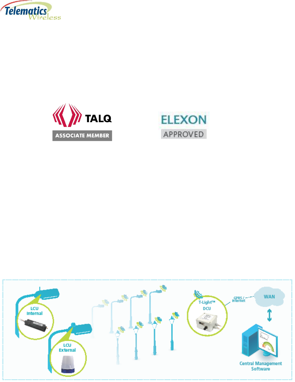
Telematics Wireless is an Associate Member of the TALQ Consortium, and its products are ELEXON-
approved.
1.1. DCU2 PRO E US Product Description
The DCU2 Pro E US belongs to the T-Light family of Telematics Wireless Smart Lighting Systems. It
enables the control and monitoring of a luminaire population of up to 1,000 light poles in the most cost-
effective and reliable way.
The DCU2 Pro E US, serves as a gateway in Telematics' robust and encrypted mesh network
communication (Tnet) to manage the information traffic and commands for each member or group of
lights. It stores status and energy consumption information for each light pole, and communicates with
the Control and Monitoring Software (CMS). The DCU2 Pro E US communicates with the CMS over
secure Internet or VPN/ APN via LAN, cellular connection, or Wi-Fi.
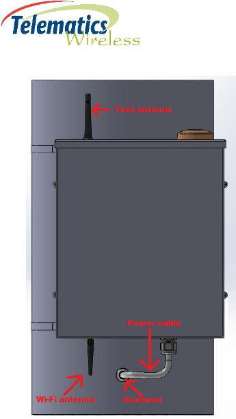
The DCU2 Pro E US is designed for outdoor use only. It is intended to be mounted directly to the light
pole, or to the preferred customer location under Telematics guidelines. After the DCU2 Pro E US is
secured to the pole, the Tnet antenna and the low profile Wi-Fi antenna are connected to the top and
bottom of the unit respectively.
Figure 1 - T-Light Pro Topology

5
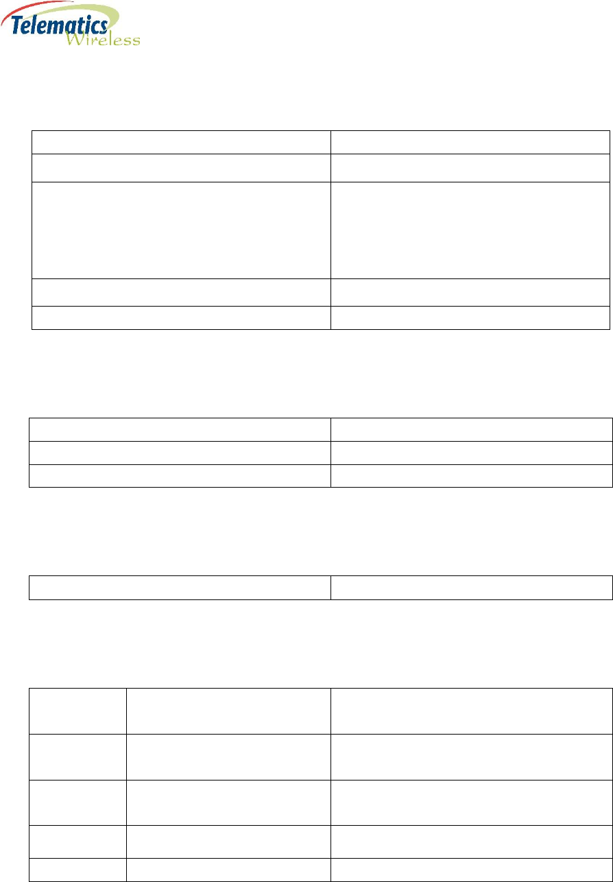
1.2. DCU2 Pro E US Components
The DCU2 Pro E US is comprised of the following main components:
Description
DCU2 Pro E Core:
Gateway modem: TNET210 module, 902-928MHz
Embedded application processor – ARM Cortex™ – A9 Dual Core running Debian Linux
Incorporates WiFi module
Motherboard with shutdown backup power
Power Supply 110-277VAC/12VDC 60 W
3G Modem with integrated GPS
Single outdoor antenna with integrated 3G and GPS
TNET Antenna 868-928MHz
WiFi antenna
12 m Eucaflex Plus neoprene AC power cable, 3x1.5, service temperature -40 to 90 C
Surge Protection Module
Surge Current 20,000 amps @ 8/20μs Waveform
2. Specifications
Radio
Parameter
Value
3G Modem with integrated GPS
GateTel GT-HE910-NAG (North America)
GateTel GT-HE910-NAD ( North America -
without GPS )
GateTel GT-HE910-EUG (Europe/Australia/NZ)
GateTel GT-HE910-EUD ( Europe/Australia/NZ
- without GPS)
Gateway (TNET210 RF module) Operating
Frequency
902 – 928 MHz North America band
915-928MHz , Australia/NZ band
Wi-Fi
802.11N Client
6
Power Interface
Parameter
Value
Universal AC Input; full range
90 ~ 305VAC@ 50-60Hz
Protections
Short circuit
Over current
Over voltage
Over temperature
Built-in active PFC
Maximum Consumption
60 W
Typical Consumption
10W
Physical Specifications
Parameter
Value
Dimensions (antenna and AC cable excluded )
410 280 x140mm
Weight
6.5kg including 12 m AC cable
Environment
Operation Temperature
-30 to 70 C
Certifications
Radio
TNET210 RF module
FCC ID: NTAT210A
IC: 4732A-T210A
GateTel GT-HE910-NAG
FCC ID: RI7HE910NA
IC: 5131A-HE910NA
SolidRun SR-uSOM-MX6
incorporates WiFi
FCC ID: 2ACMW-MX6
IC: 12107A-MX6
EMC
FCC 47CFR part 15 subpart B , ICES-003
Safety
IEC 60950-1

7
3. Regulation Information
FCC Part 15 Regulation Class B device
The digital circuit of this device has been tested and found to comply with the limits for a Class B
digital device, pursuant to part 15 of the FCC Rules. These limits are designed to provide
reasonable protection against harmful interference in a residential installation. This equipment
generates uses and can radiate radio frequency energy and, if not installed and used in
accordance with the instructions, may cause harmful interference to radio communications.
However, there is no guarantee that interference will not occur in a particular installation. If this
equipment does cause harmful interference to radio or television reception, which can be
determined by turning the equipment off and on, the user is encouraged to try to correct the
interference by one or more of the following measures:
-Reorient or relocate the receiving antenna.
-Increase the separation between the equipment and receiver.
-Connect the equipment into an outlet on a circuit different from that to which the receiver
is connected.
-Consult the dealer or an experienced radio/TV technician for help.
Industry Canada Class B Notice
This device complies with Industry Canada’s licence-exempt RSSs. Operation is subject to the
following two conditions:
(1) This device may not cause interference; and
(2) This device must accept any interference, including interference that may cause undesired
operation of the device.
Le présent appareil est conforme aux CNR d’Industrie Canada applicables aux appareils radio
exempts de licence. L’exploitation est autorisée aux deux conditions suivantes :
(1) l’appareil ne doit pas produire de brouillage;
(2) l’utilisateur de l’appareil doit accepter tout brouillage radioélectrique subi, même si le
brouillage est susceptible d’en compromettre le fonctionnement.
FCC interference Notice
This device complies with part 15 of the FCC rules. Operation is subject to the following two
conditions:
(1) This device may not cause interference; and
(2) This device must accept any interference, including interference that may cause undesired
operation of the device.

8
FCC and Industry Canada Radiation Hazard Warning
The antenna used for this transmitter must be installed to normally provide minimum
separation distance of at least 20 cm from all persons.
Le dispositif doit être placé à une distance d'au moins 20 cm à partir de toutes les
personnes au cours de son fonctionnement normal. Les antennes utilisées pour ce
produit ne doivent pas être situés ou exploités conjointement avec une autre antenne
ou transmetteur.
Requirements for the antenna with regards to FCC/IC
compliance
This radio transmitter (M/N: DCU2 PRO E US) has been approved by Industry Canada to
operate with the antenna types listed below with the maximum permissible gain
indicated. Antenna types not included in this list, having a gain greater than the
maximum gain indicated for that type, are strictly prohibited for use with this device.
Le présent émetteur radio (M/N: DCU2 PRO E US) a été approuvé par Industrie Canada
pour fonctionner avec les types d'antenne énumérés ci-dessous et ayant un gain
admissible maximal. Les types d'antenne non inclus dans cette liste, et dont le gain est
supérieur au gain maximal indiqué, sont strictement interdits pour l'exploitation de
l'émetteur.
4. Antennas specification
TNET Antenna
Manufacturer: V.Torch, Model no. VTGSMA-70 , or equivalent.
Parameter
Value
Frequency
868-928 MHz
Gain
2dBi
Polarization
Vertical
9
Wi-Fi Antenna
Manufacturer: Taoglas, Model no. GW.26.0111, or equivalent.
Parameter
Value
Frequency
2.4-2.5Ghz
Gain
1 dBi
Polarization
Vertical
3G Antenna
Parameter
Value
Frequency
824-960MHz/ 1710-2170MHz
Gain
2 dBi
Polarization
Linear
GPS Active Antenna
Type
Parameter
Value
Dielectric
Center Frequency
1575.42 1MHz
Gain
0dBic (Zenith)
LNA
Gain
22 2dB
Noise Figure
< 1.5
Supply Voltage
3V DC
Current Consumption
9mA
5. Installation Overview
Important Note: Read the entire Installation Guide before beginning the installation process.
The installation process consists of the following stages, detailed in the following sections:
Pre-Installation. See 6. Pre-Installation.
◦ Review of requirements and guidelines.
◦ Verify pole has appropriate circuit breaker.
◦ Preparation of Android smartphone with TMLW DCU Checkup app.
Installation. See 7. Installing the DCU2 Pro E US.

10
◦ Attach antennas to DCU2 Pro E US.
◦ Place unit on pole and secure with steel tape.
◦ Drill hole at location on pole where power cable will enter and insert grommet.
◦ Insert 12 meter AC power cable from DCU2 Pro E US through grommet in pole.
◦ Connect end of 12 meter power cable to circuit breaker.
◦ Using the prepared Android smartphone, scan the barcode on the side of the DCU2 Pro E US
unit and test the communication to the CMS.
5.1. Safety Guidelines
Before you begin the installation of, use, or perform any service operation on the DCU2 Pro E US, read
the following safety information.
Attention to these warnings will help prevent personal injuries, and damage to the DCU2 Pro E US.
It is your responsibility to use the DCU2 Pro E US in an appropriate manner:
The DCU2 Pro E US is only for use on a stable and sturdy street light pole.
The DCU2 Pro E US must not be used in any way that may cause personal injury or property damage.
Make sure that the installation process including the pole selection is approved by a construction
engineer.
You are responsible if the DCU2 Pro E US is used in any way other than its designed purpose, or contrary
to Telematics Wireless instructions. Telematics Wireless shall assume no responsibility for such use of
the DCU2 Pro E US.
The DCU2 Pro E US is used for its designated purpose only if it is used in accordance with its product
documentation and within its performance limits.
Using the DCU2 Pro E US requires technical skills, and a basic knowledge of English. It is therefore
essential that only skilled and specialized staff, or thoroughly trained personnel with the required skills,
be allowed to use the product.
Keep the basic safety instructions and the product documentation in a safe place, and make them
available to subsequent users.
Note: Applicable local or national safety regulations and rules for the prevention of accidents
must be observed in all work performed.
Warning: This section contains general guidelines, and does not include every potentially hazardous
situation. When you install the DCU2 Pro E US, always use common sense and caution.
5.1.1. General Safety Guidelines
The following safety guidelines should always be followed:
Never attempt to lift an object that might be too heavy for you to lift by yourself.
Always disconnect the power source and unplug all power cables before lifting or moving the DCU2
Pro E US components.
11
Keep the work area clear and clean during and after installation.
Keep tools and equipment components away from walkways.
Do not wear loose clothing, jewelry (including rings and chains), or other items that could get caught
in the equipment.
Fasten your tie or scarf and sleeves.
Operate Telematics Wireless equipment safely by using it in accordance with its electrical ratings
and product usage instructions.
Do not work alone if potentially hazardous conditions exist.
Always unplug the power cables when performing maintenance or working on the equipment.
Ensure that the installation of the DCU2 Pro E US is in compliance with national and local electrical
codes:
◦ In the United States: National Fire Protection Association (NFPA) 70, United States National
Electrical Code (NEC).
◦ In Canada: Canadian Electrical Code (CEC).
◦ In other countries: International Electro technical Commission (IEC) 364.
5.1.2. Compliance and Safety Information
The Telematics Wireless T-Light DCU2 Pro E US is designed to meet regulatory compliance and safety
approval requirements.
5.1.3. Energy Hazard
The Telematics Wireless T-Light DCU2 Pro E US is configured to use AC-input power only.
Hazard Warning: Hazardous voltage or energy may be present on power terminals.
Do not touch terminals while they are live to prevent injury or death.
Always replace terminal covers after working on the power connections.
5.1.4. Preventing Electrostatic Discharge Damage
The components of the DCU2 Pro E can be damaged by static electricity. Not implementing the proper
electrostatic discharge (ESD) precautions can result in intermittent or complete component failures.
To prevent ESD before performing any procedure:
1. Attach an ESD-preventive strap to your wrist.
2. Use an alligator clip to connect the strap leash to an open metal part of the cabinet.
Note: To minimize the potential for ESD damage, always use an ESD-preventive antistatic
wrist strap (or ankle strap), and ensure that it makes good skin contact.
Note: The ESD-preventive antistatic strap is not provided by Telematics Wireless.
12
Caution: Check the resistance value of the ESD-preventive strap periodically. The measurement should be
between 1 and 10 mega ohms.
6. Pre-Installation
It is important to note the following information before starting the installation process:
The DCU2 Pro E US is fully factory tested prior to shipment. In addition to testing each component of
the system, the RF output power and RSSI level are tested to verify that they are within acceptable
ranges.
The shipping package for the DCU2 Pro E US is engineered to reduce the chances of product damage
associated with routine material handling experienced during shipment.
Important Note: The DCU2 Pro E US should always be transported or stored in its shipping package
in the upright position. Keep the DCU2 Pro E US in the shipping container until you have determined
the installation site.
Following the installation procedure in the order described in this document is critical, so as to avoid
possible damage to any of the components.
Important Note: Do not attempt to attach any cables before physically installing the DCU2 Pro E US
in its intended location.
Before installing the Telematics Wireless T-Light DCU2 Pro E US product:
Inspect all items for shipping damage. If an item appears damaged, contact a Telematics Wireless
customer service representative immediately.
Obtain customer-supplied equipment. See 3.1. Mandatory Customer-Supplied Current Surge
Protection and 3.2. Required Tools and Equipment.
Verify power and cabling requirements.
Analyze installation location for any issues with:
◦ Siting requirements, such as line-of-site to end units.
◦ Access to pole.
◦ Environmental conditions, such as dampness.
Review safety guidelines.
6.1. Mandatory Customer-Supplied Current Surge Protection
System integrity for the DCU2 Pro E US is ensured with the mandatory installation of customer-supplied
current surge protection equipment.
Warning: To prevent damage due to power network current surges, it is mandatory that you also
provide and install a circuit breaker to protect the DCU2 Pro E US.
13
6.2. Required Tools and Equipment
Before starting the installation of the DCU2 Pro E US, ensure that the necessary customer-supplied tools
and equipment are available:
Circuit breaker for power supply
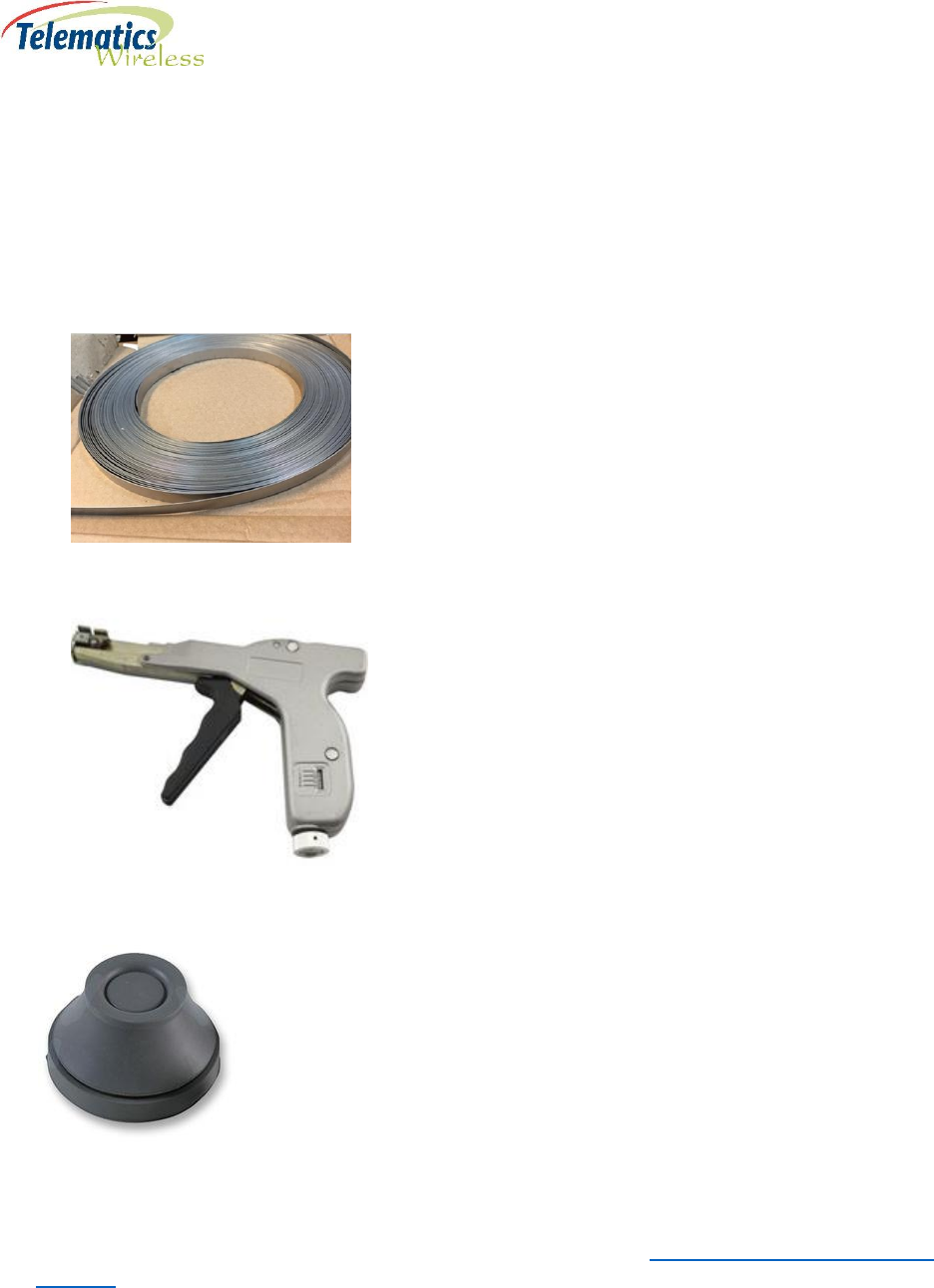
12 mm x 1 mm AISI 304, tensile strength 517(N/mm2), non-adhesive stainless steel tape, sufficient
to secure unit to pole
Tensioning tool for steel tape
Grommet, M20 size for outdoor power, to seal entry of DCU2 Pro E US power cable into pole, similar
to the following:
Standard drill
Android smartphone with a camera and a working network connection for verifying the
communication of the installed DCU2 Pro E US. Telematics-Wireless will provide a license key and
their DCU Checkup app for installation on the smartphone. See 3.7. Preparing Smartphone for
Scanning.

14
6.3. Installation and Accessories Kit Parts List
The DCU2 Pro E US is delivered without the antennas installed, unless otherwise ordered. The DCU2 Pro
E US unit comes with the following components from Telematics:
Tnet antenna.
Wi-Fi antenna.
DCU2 Pro E US with attached 12 meter power cable.
6.4. Site Requirement Guidelines
The DCU2 Pro E US is most commonly installed on a light pole, but can be installed on other locations
that are high enough to provide line-of-sight to the end units.
Telematics Wireless recommends that the site for the DCU2 Pro E US conforms to the following
conditions:
Away from sources of vibration or physical shock.
Isolated from strong electromagnetic fields produced by electrical devices.
Properly grounded.
To help maintain trouble-free operation, adhere to the following precautions and guidelines when
planning the Telematics Wireless T-Light DCU2 Pro E US installation:
The DCU2 Pro E US should be installed with means for a permanent ground.
Ensure the site includes provisions for an AC power source, grounding, and RF cable.
Keep cables organized. Make sure that cables from other equipment installed in the vicinity do not
restrict access to the DCU2 Pro E US.
Verify that there is sufficient clearance between the DCU2 Pro E US system and any other system
that may exhaust warm air.
6.5. Power Connection Guidelines
The DCU2 Pro E US is configured to use AC-input power only. Ensure all power connection wiring
conforms to the rules and regulations of the country and local authorities.
The system accepts a range input voltage of for:
EU -90VAC or 295VAC.
US -90 ~ 305VAC@ 50-60Hz
Proper grounding is necessary to avoid damage from lightening and power surges. The grounding design
must comply with the country and local electrical codes.
Additional surge protection is required for the DCU2 Pro E US. See 3.1. Mandatory Customer-Supplied
Current Surge Protection.
15
Warning: There must be a permanent ground from the main power source to the DCU2 Pro E
US. Whenever it is likely that the protection has been impaired, disconnect the power cord until
the ground has been restored.
6.6. Preparing Android Smartphone
A smartphone app provided by Telematics is required for scanning the DCU2 Pro E US barcode and
testing its connection to the CMS.
How to prepare smartphone:
1. On an Android smartphone with a camera:
a) Enable network connectivity.
b) Download and install the DCU Checkup app which your Telematics representative will
provide.
2. Open the DCU Checkup app and input the license key received from Telematics.
Entering the license key before the installer uses the app in the field will save the installer from
having to remember the key.
7. Installing the DCU2 Pro E US on a Light Pole
The general steps are:
Installing the circuit breaker, if not already installed.
Physical placement and securing of the DCU2 Pro E US on the pole.
Installing the antennas.
Drilling a hole for the grommet and power cable.
Inserting DCU2 Pro E US 12 m power cable through grommet and into the pole
Connecting theDCU2 Pro E US power cable to the circuit breaker.
Scanning the barcode and testing the data communication using the prepared smartphone.
To install the DCU2 Pro E US:
1. Turn the pole power OFF.
2. Position the DCU2 Pro E US on the pole as follows:
◦ The DCU2 Pro E US should be installed at the highest possible point on the pole, as approved by
Telematics.
◦ Position the DCU2 Pro E US so that the Tnet antenna with TNC connector will face upwards, in
order to provide the greatest line-of-sight for the end units as possible.
Note: If the location of the Tnet antenna will not provide a reliable line-of-sight for the end units,
contact Telematics for assistance.
3. Thread the steel tape through the slots in the upper and lower mounting brackets.
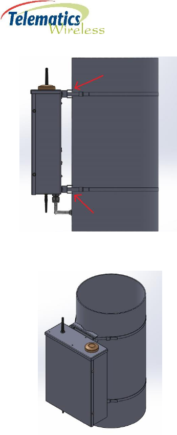
16
4. Tighten the steel tape around the light pole using the tensioning tool in order to secure the
mounted DCU2 Pro E US.
5. Attach the TNET antenna with the TNC connector to the antenna port on the top of the DCU2 Pro E
US.
6. Attach the low-profile Wi-Fi antenna to the antenna port on the bottom of the DCU2 Pro E US.
7. Drill a 20.5 mm mounting hole for grommet into the pole. The hole should be close to the DCU2 Pro
E US but with enough distance so as not to interfere with the cable connections of the DCU2 Pro E
US.
8. Insert the grommet into its mounting hole.
9. Insert the DCU2 Pro E US power cable through the grommet and into the pole.
17
10. Attach the DCU2 Pro E US power cable to the circuit breaker.
11. Turn the pole power ON.
12. Wait 10 minutes to ensure the DCU2 Pro E US has fully loaded.
13. Using the Android smartphone with the Telematics DCU Checkup app installed:
1. Tap Scan and scan the barcode on the side of the DCU2 Pro E US.
The Test window will open with the scanned details at the top.
2. In the middle bar, select Antenna Connected and Power Connected.
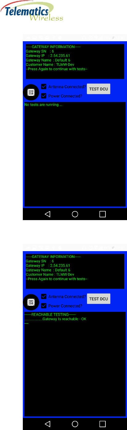
18
3. Tap TEST DCU.
The status of the tests running will appear:
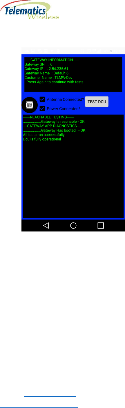
19
When the tests have finished successfully, the ‘All tests ran successfully’ and ‘Dcu is fully
operational’ messages will appear:
Note: If the DCU tests did not run successfully, contact Telematics support for assistance in
troubleshooting.
8. Contact Details
Contact your local Telematics technical support representative, or contact us at:
Telematics Wireless, Ltd.
26 Hamelacha St., POB 1911
Holon 58117
ISRAEL
Phone: +972-3-557-5763
Fax: +972-3-557-5703
Sales: sales@tlmw.com
Support: support@tlmw.com
www.telematics-wireless.com