STI Engineering 9256OEM Radio Modem Module User Manual PDF995 Job 3
STI Engineering Pty Ltd Radio Modem Module PDF995 Job 3
Manual

RFI-9256 RADIO MODEM
USER MANUAL

RFI-9256 Radio Modem
User Manual
DISCLAIMER
© 2004 RF Innovations Pty Ltd. All rights reserved.
RF Innovations reserves the right to make improvements on the product in this manual at any time without
notice.
No part of this manual may be produced, copied, translated, or transmitted in any form or by any means
without the written permission of RF Innovations.
Information provided in this manual is intended to be accurate and reliable. However, RF Innovations
assumes no responsibility for its use or infringements upon the rights of third parties that may result from its
use.
FCC NOTIFICATIONS
This device must be operated as supplied by RF Innovations. Any changes or modifications made to the
device without the express written approval of RF Innovations may void the user's authority to operate the
device.
This device complies with Part 15 of the FCC rules. Operation is subject to the following two conditions: 1)
this device may not cause harmful interference and 2) this device must accept any interference received,
including interference that may cause undesired operation.
This equipment has been tested and found to comply with the limits for a Class B digital device, pursuant to
Part 15 of the FCC Rules. These limits are designed to provide reasonable protection against harmful
interference in a residential installation. This equipment generates, uses and can radiate radio frequency
energy and, if not installed and used in accordance with the instructions, may cause harmful interference to
radio communications. However, there is no guarantee that interference will not occur in a particular
installation. If this equipment does cause harmful interference to radio or television reception, which can be
determined by turning the equipment off and on, the user is encouraged to try to correct the interference by
one or more of the following measures:
• Reorient or relocate the receiving antenna.
• Increase the separation between the equipment and receiver.
• Connect the equipment into an outlet on a circuit different from that to which the receiver is
connected.
• Consult the dealer or an experienced radio/TV technician for help.
Reference No. MAN0005
Revision 3.6
August 2004

Contents
RFI-9256 Radio Modem User Manual Page 3 of 96
Contents
1.
Introduction ............................................................................................................................................................................. 5
1.1
OEM Applications............................................................................................................................................................ 5
1.2
Product Overview............................................................................................................................................................. 5
2.
Installation................................................................................................................................................................................ 6
2.1
Radio Frequency Hazard Information ............................................................................................................................. 6
2.2
RFI-9256 Location ........................................................................................................................................................... 6
2.3
Antenna Installation......................................................................................................................................................... 6
3.
Configuration ........................................................................................................................................................................... 7
3.1
User Interfaces ................................................................................................................................................................. 7
3.2
Terminal Menu Interface.................................................................................................................................................. 7
3.3
Hayes AT Command Interface ......................................................................................................................................... 8
3.4
Front Panel Interface..................................................................................................................................................... 10
4.
Operation................................................................................................................................................................................ 14
4.1
Serial Port Operation..................................................................................................................................................... 14
4.2
Radio Operation............................................................................................................................................................. 17
4.3
Protocol Operation ........................................................................................................................................................ 26
4.4
Auxiliary I/O................................................................................................................................................................... 27
5.
Applications............................................................................................................................................................................ 27
5.1
Basic Point-to-point Network......................................................................................................................................... 27
5.2
Simplex Point-to-point Network ..................................................................................................................................... 27
5.3
Multiple Slave Point-to-point Network........................................................................................................................... 27
5.4
Point-to-point Network with Back-to-back Repeaters.................................................................................................... 27
5.5
Broadcast Network......................................................................................................................................................... 27
5.6
Broadcast Network with Back-to-back Repeaters.......................................................................................................... 27
5.7
Hayes Dial-up Networking............................................................................................................................................. 27
5.8
Dial-up Networking with Back-to-back Repeaters......................................................................................................... 27
5.9
SCADA Network with Routing Table ............................................................................................................................. 27
5.10
SCADA Network with a Back-to-back Repeater ............................................................................................................ 27
5.11
Point-to-point Auxiliary I/O........................................................................................................................................... 27
5.12
Point-to-point Auxiliary I/O with a Back-to-back Repeater........................................................................................... 27
5.13
Hayes Dial-up Auxiliary I/O .......................................................................................................................................... 27
Appendix A
Technical Specifications ..................................................................................................................................... 27
A.1
Radio Specifications....................................................................................................................................................... 27
A.2
Connector Pin Assignments ........................................................................................................................................... 27
A.3
Back-to-back Repeater Connector ................................................................................................................................. 27
A.4
Power Supply Notes ....................................................................................................................................................... 27

Contents
RFI-9256 Radio Modem User Manual Page 4 of 96
A.5
Version Numbering Scheme ........................................................................................................................................... 27
A.6
Case Dimensions ............................................................................................................................................................ 27
Appendix B
Terminal Menu Reference ................................................................................................................................. 27
B.1
(R) Radio Configuration Menu....................................................................................................................................... 27
B.2
(L) Protocol Port Selection Menu .................................................................................................................................. 27
B.3
(S) Serial Port Configuration Menu............................................................................................................................... 27
B.4
(M) Radio and I/O Configuration Menu ........................................................................................................................ 27
B.5
(P) Radio Personality Menu........................................................................................................................................... 27
B.6
(D) Diagnostics Menu .................................................................................................................................................... 27
Appendix C
Hayes AT Command Reference ........................................................................................................................ 27
C.1
Radio Commands ........................................................................................................................................................... 27
C.2
S-Register Commands .................................................................................................................................................... 27
C.3
‘%’ Register Commands................................................................................................................................................. 27
C.4
Other Commands ........................................................................................................................................................... 27
C.5
Summary of Commands.................................................................................................................................................. 27
Appendix D
Factory Defaults.................................................................................................................................................. 27
Appendix E
Glossary ............................................................................................................................................................... 27
Introduction
RFI-9256 Radio Modem User Manual Page 5 of 96
1. Introduction
The RFI-9256 is a frequency-hopping spread spectrum (FHSS) radio modem operating in the international
900MHz ISM band. It has been type approved for operation in Australia (915-928MHz), New Zealand (921-
929MHz), and countries regulated by the FCC (902-928MHz).
The RFI-9256 is suitable for many applications including point-to-point, point-to-multipoint, and SCADA
protocol networks.
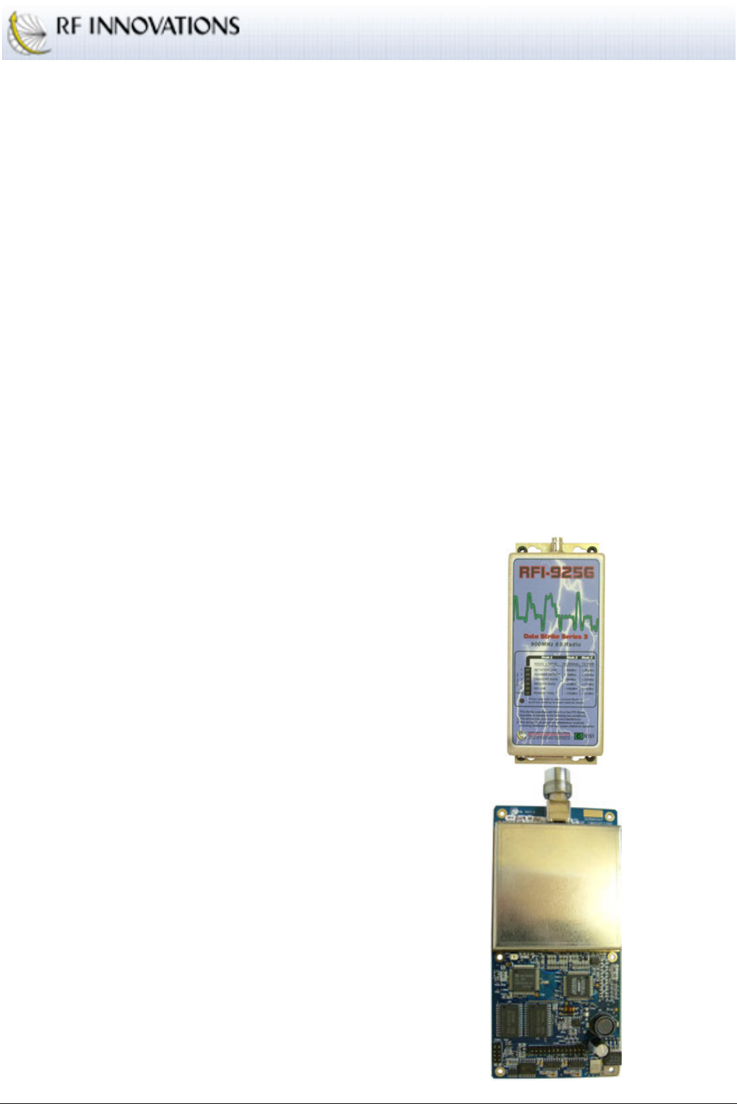
1.1 OEM Applications
An RFI-9256 OEM module is available for OEM applications.
When used in modular applications, the device where the module is fitted will be required to display on the
outside and in a clearly visible area the notice: “Contains FCC ID: P5M9256OEM”
Under FCC regulations, use of certain antennas may require a Class II permissive change from the FCC.
Please contact RF Innovations for more information.
1.2 Product Overview
CRC error detection and recovery via
retries
Up to 30km point-to-point
Dual RS-232 serial ports
User selectable interface speeds between
110 and 115200bps
1 W (30dBm) RF output power
Programmable I/O for SCADA
applications
Front panel indicators for RSSI, TX
power, and status
Can be installed and commissioned
without test equipment.
Sensitivity <-108dBm for BER 1 part in
10-4
Operating voltage 9 to 30VDC
Operates at -10ºC to +60ºC with 95% non-
condensing humidity
Protocol routing modes.

Installation
RFI-9256 Radio Modem User Manual Page 6 of 96
2. Installation
2.1 Radio Frequency Hazard Information
The product described in this manual has been tested to comply with Maximum Permissible Exposure
(MPE) limits.
When operated with the supplied antenna and at maximum transmit power
1
, the antenna should not be
located within 20cm of where people may come in contact.
Antennas of this transmitter must not be co-located or operating in conjunction with any other antenna or
transmitter.
2.2 RFI-9256 Location
There are a number of rules to observe when installing your RFI-9256.
Placement of the RFI-9256 unit is likely to have a significant impact on its performance. The
higher the placement of the antenna, the better the communication link.
Antennas should be placed away from walls and poles as these will affect the radiated pattern and
VSWR.
Antennas in close proximity are potential sources of mutual interference. It is possible that slight
adjustments in antenna placement (as little as 1 meter in either vertically or horizontally) may
solve interference problems.
The radio should be placed away from computers, telephones, answering machines and other
similar equipment.
Long RS-232 cable runs (greater than 10 meters) should be avoided in areas with frequent
lightning activity or static electricity build-up. Nearby lightning strikes or elevated levels of static
electricity may lead to voltage spikes on the RS-232 circuits with potential failure of the interface.
RF Innovations supplies a range of external data interface converters for applications requiring
long cable runs.
2.3 Antenna Installation
Use extreme caution when installing antennas and follow all instructions provided.
Any antennas placed outdoors must be properly grounded. The use of external antennas subjects the
transceiver to greater exposure to direct lightning strikes.
RF Innovations recommends use of lightning surge arrestors to protect all antennas and attached equipment
against lighting strike.
1
Transmit power set to 1W (+30dBm) and antenna gain 3dBd (5.15dBi).

Configuration
RFI-9256 Radio Modem User Manual Page 7 of 96
3. Configuration
3.1 User Interfaces
The RFI-9256 provides three user interfaces that allow the radio to be configured for a diverse range of
applications.
1. Terminal menu interface. A menu system is available over either of the RFI-9256’s serial ports.
This menu interface can be accessed through a terminal emulation program, such as RFI InTerm.
2. AT command interface. The AT command interface is used to configure and control to the RFI-
9256 through ASCII Hayes attention commands. This can be used to adjust the radio’s configuration,
read the radio’s configuration, and read performance parameters.
3. Front panel interface. The front panel interface consists of six dual colour (red / green) LEDs and a
push button. This panel can display the radio status, RSSI, transmit power, temperature, and main
serial port status.
3.2 Terminal Menu Interface
The terminal menu provides access to all configuration parameters in the radio. There are three methods for
accessing the terminal menu:
1. Execute the
AT?
command at the Hayes AT command interface. See section 3.3 information on
executing AT commands.
2. Dial a remote radio’s menu system using AT commands. See section 4.3.3 for more information on
connected to remote radios via AT commands. When a menu system is accessed remotely its
functionality is limited in order to prevent a configuration change that would break the connection.
3. Select mode 6 on the front panel interface. See section 3.4 for information on selecting front panel
modes.
The terminal menu has the following features:
The terminal menu can be password protected to prevent unauthorised users for reading or
changing the radio configuration.
If a terminal menu is enabled, but there is no input for a configurable period of time, then the
terminal menu will disable itself. By default the terminal menu is disabled after 15 minutes.
Only 1 terminal menu can be available at any one time. This is done to prevent multiple users from
changing the configuration of a single radio at the same time.
The full terminal menu reference is provided in Appendix B.

Configuration
RFI-9256 Radio Modem User Manual Page 8 of 96
3.3 Hayes AT Command Interface
The RFI-9256 supports many Hayes compatible commands enabling the user to fully control and operate the
radio, and in most cases emulate public switch telephone network (PSTN) modems.
Hayes commands may be entered manually through a terminal or automatically through dial-up network
applications and scripts. Most commands, with exception of the ‘%’ register and connection commands, may
be concatenated into a single command string. Commands or command strings must be terminated with a
carriage return (ASCII 13
D
, produced by the enter key).
3.3.1 The AT Commands
THE ATTENTION CODE
The attention commands are a group of commands recognised by the radio. All attention commands are
prefixed by the letters AT, and are referred to as AT commands. For example, the command:
ATI3<CR>
Causes the radio to return its firmware version information:
Firmware: 9256 Version 1.30 Rev.D Australia
OK
The attention code, along with all AT commands, is case insensitive.
MULTIPLE COMMANDS
Multiple commands can be placed after an
AT
provided that the total number of characters does not exceed
255. For example, a valid command to display the radio’s firmware version information and internal
temperature is:
ATI3I9<CR>
This results in the output:
Firmware: 9256 Version 1.30 Rev.D Australia
25.5c
OK
S-REGISTER AND %-REGISTER COMMANDS
S-registers and %-registers are used to store complex configuration parameters. In order to set the value of
an s-register or %-register the following format is used:
Configuration
RFI-9256 Radio Modem User Manual Page 9 of 96
ATS<r>=<n><CR>
AT%<r>=<n><CR>
Where
<r>
is the register, and
<n>
is the data. The current value of an s-register or %-register can be
retrieved through a command of the form:
ATS<r><CR>
AT%<r><CR>
A list of all s-registers can be found in Appendix C.2, while all %-registers are listed in Appendix C.3.
RESPONSE CODES
Whenever an AT command is executed a response code is generated. Response codes can be either strings,
numbers, or be suppressed (not output to the user). The list of response codes generated by the RFI-9256 is
shown in Table 1.
Response
String
Response
Number Description
OK
0 The command executed successfully.
CONNECT
1 A connection has been established between this radio and another radio.
RING
2 Another radio is ringing this radio and attempting to establish a connection.
NO CARRIER
3 A connection could not be established or it has been dropped.
ERROR
4 A command was formatted incorrectly.
BUSY
7 An attempt was made to dial a remote unit and it responded with a busy
signal.
NO ANSWER
8 An attempt was made to dial a remote unit but it could not be contacted
Table 1: AT response codes generated by the RFI-9256
3.3.2 Configuring the Radio
The radio uses s-registers to alter the configuration profile. Each s-register contains a decimal value, an
ASCII character or an ASCII string. The interpretation of each value differs with each s-register.
The radio allows the contents of the s-registers to be saved to non-volatile memory using the
AT&W
command. The entire configuration profile will be retained after the radio has been powered off.
The radio also has factory default settings stored internally, allowing all communication settings and s-
register values to be set to the factory default configuration. The factory defaults have been selected so most
users will be able to make immediate use of their radio, with minimum changes. The default settings are
listed in Appendix D.
Configuration
RFI-9256 Radio Modem User Manual Page 10 of 96
Factory defaults can be restored using the
AT&F
command.
The
AT&V
(view) command outputs the current configuration of the radio.
The complete AT command reference is provided in Appendix C, while the use of Hayes AT commands to
establish dial-up networking connections is discussed in section 4.3.3.
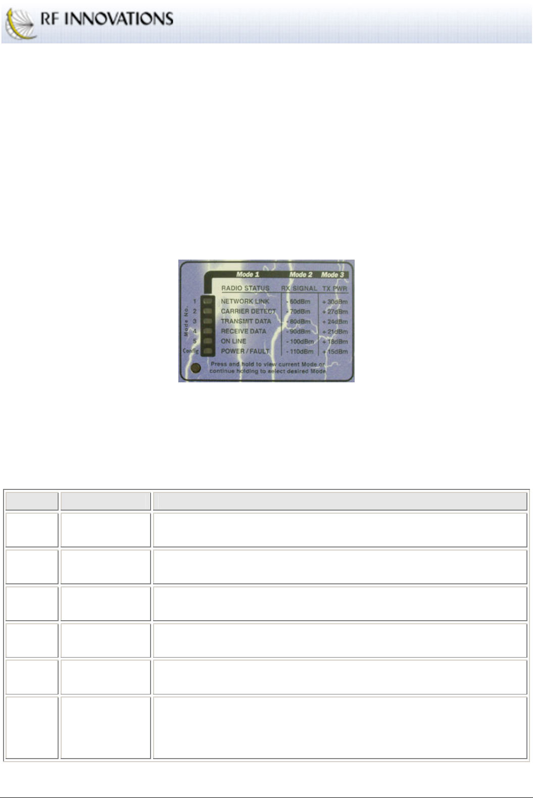
3.4 Front Panel Interface
The front panel interface allows for real-time monitoring of radio parameters without requiring any external
equipment. The front panel can also be used to enable the menu on the RFI-9256’s auxiliary port regardless
of the current serial port configuration. The front panel is shown in Figure 1.
Figure 1: RFI-9256 front panel
There are six front panel modes. In order to select a front panel mode press the front panel button. This will
display the current panel mode by highlighting a single LED red. In order to select another front panel mode,
continue to hold the button until the LED scrolls down to the appropriate LED before releasing. The list of
LED modes is shown in Table 2.
LED Mode Function
1 (top) Radio Status Section 3.4.1 describes the functionality of the LEDs when in radio status
mode.
2 RSSI Provides a bar displays of the average received single strength indication
(RSSI) for this radio. Table 3 shows the level for each bar item.
3 Tx Power Provides a bar display of the transmit power for the radio. Table 3 shows
the level for each bar item.
4 Temperature Provides a bar display of the current internal temperature. Table 3 shows
the level for each bar item.
5 Main Serial
Port Shows the main serial port status. The meaning of each individual LED is
shown in Table 4.
6
(bottom) Configuration
When mode 6 is selected, the terminal menu will be enabled on the
auxiliary port at 19200, 8N1, with no flow control. Once configuration
mode is selected and the terminal menu enabled, the front panel displays
the same settings as for radio status mode.
Table 2: Front panel modes
Configuration
RFI-9256 Radio Modem User Manual Page 11 of 96
Front panel modes 2, 3, and 4 all display a bar graph to indicate the level of RSSI, transmit power, and
temperature respectively. The top LED that is lit indicates the current value, if the LED is lit green then the
value shown in Table 3 applies, while if the LED is lit red then the current value is half way between the
listed value in Table 3 and the previous value.
LED RSSI Tx Power Temperature
0 -60dBm +30dBm 60ºC
1 -70dBm +27dBm 50ºC
2 -80dBm +24dBm 40ºC
3 -90dBm +21dBm 30ºC
4 -100dBm +18dBm 20ºC
5 -110dBm +15dBm 10ºC
Table 3: RSSI, Tx Power, and Temperature displays
LED Name Function
0 DTR The current state of the DTR input on the main port. Red indicates +12V, while green
indicates -12V.
1 DCD The current state of the DCD output on the main port. Red indicates +12V, while green
indicates -12V.
2 TX Flashes while RS-232 data is transmitted by the radio on the main serial port.
3 RX Flashes while RS-232 data is being received by the radio on the main serial port.
4 RTS The current state of the RTS input on the main port. Red indicates +12V, while green
indicates -12V.
5 CTS The current state of the CTS output on the main port.. Red indicates +12V, while green
indicates -12V.
Table 4: Main serial port LED function
3.4.1 Radio Status LEDs
NETWORK LINK
When network link is green it shows that the unit can hear a remote radio that is on the same network and
hopping pattern. Slave radios should show network link constantly, as master radios are constantly
transmitting network synchronization messages. Master radios will only show network link when connected
to a slave in point-to-point, Hayes dial-up mode, or when receiving user data.
In a radio network with a strong signal (better than -90dBm), network link should be predominately green, it
may go red from time to time, but should not go off. A red network link indicator means that the radio has
temporarily lost the remote unit. This should occur infrequently.

Configuration
RFI-9256 Radio Modem User Manual Page 12 of 96
CARRIER DETECT
When carrier detect is green it shows that the unit can hear a remote radio. Slave radios in a network should
always show carrier detect, as master radio radios are constantly transmitting a synchronization signal.
Master radios however will only show this LED when connected to a slave in point-to-point or Hayes dial-
up mode, or when receiving user data. Generally it can be assumed that if a slave can hear its master then the
master can also hear its slave.
In a good radio network carrier detect should be predominately green with flashes of red. A flash of red
indicated that one RF packet has been lost. It is acceptable, and expected, that some RF packets will be lost
as the RFI-9256 operates in an industrial, scientific, and military band (ISM) where there is a potential for
interference from other radios. A red flash of carrier detect does not mean user data has been discarded, as
the RFI-9256 will retry any packet that is lost or corrupted during transmission.
TRANSMIT DATA
Transmit data indicates that data is being pushed out of the radio serial port; the colour of the LED does not
matter. The LED indicates that data has been received from a remote radio and transmitted out of either the
main or auxiliary serial port. If the LED is lighting up, but the end unit is not receiving data it could indicate
a damaged/broken serial cable, latency issues with the protocol of the end device, or incorrect serial port
configuration.
The transmit data LED will also flash when local Hayes commands are issued or the terminal menu is being
used.
RECEIVE DATA
Receive data indicates that data is being pushed into the radio serial port; the colour of the LED does not
matter. The LED indicates that data has been received from the end unit on either the main or auxiliary serial
port and sent through to the remote radio. If the remote radio is not receiving the RF data, given there is a
sufficient RF path (as indicated by the carrier detect and network link LEDs), there may be a problem with
the radio addressing or protocol routing in the radio set-up.
The transmit data LED will also flash when local Hayes commands are issued or the terminal menu is being
used.
ONLINE
When the online LED is green it shows that a packet has been received from a remote unit. The Online LED
will remain green while two units are connected in point-to-point mode or Hayes dialup mode. It is not
expected that the online LED will flash red in mode 1, a red Online LED indicates that there is something
wrong with the RF link, including mismatched frame time, directional bias settings, or a poor signal path.
POWER / FAULT
The power/fault LED indicates whether there is something seriously wrong with the radio configuration. In
normal operation the power/fault LED will flash green. When the Power LED flashes red there is most likely
something wrong with the serial configuration between the radio and the end device. The red LED can also
indicate an internal fault in the radio; the diagnostics fault log menu can provide more information. There are
two possibilities for the power/fault LED flashing red.

Configuration
RFI-9256 Radio Modem User Manual Page 13 of 96
The firmware image has become corrupted. If this is the case and the diagnostics status menu
can be reached, then it will display the message "Firmware CRC mismatch."
A framing, parity, overrun, or overflow occurs on either serial port. In this case the error is
latched for 500ms before being cleared.
Operation
RFI-9256 Radio Modem User Manual Page 14 of 96
4. Operation
4.1 Serial Port Operation
The RFI-9256 radio has two data communications equipment (DCE) RS-232 serial ports provided on a
single DB25 connector. The DB25 pin out can be found in Appendix A.
The main port supports:
TX, RX, and GND.
RTS and DTR inputs.
CTS and DCD outputs.
While the auxiliary port supports:
TX, RX, and GND.
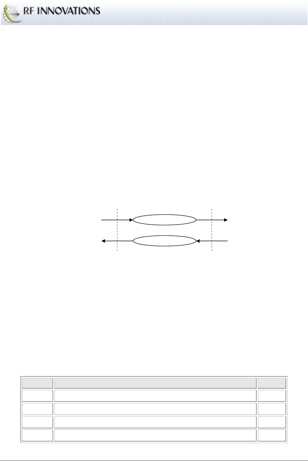
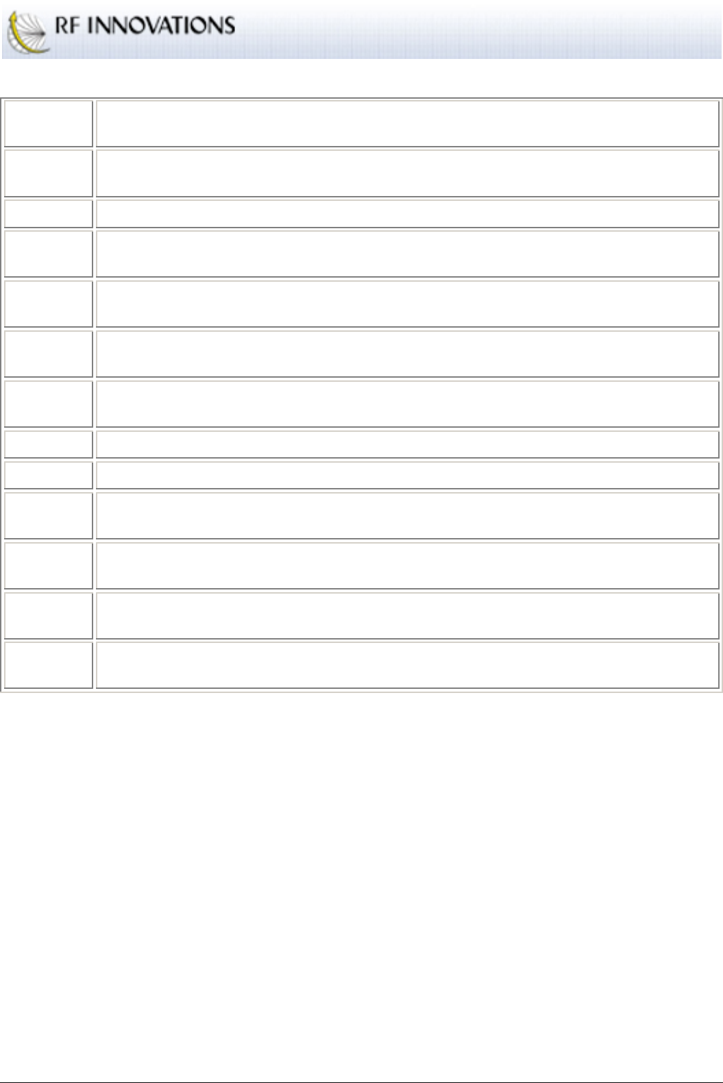
Both main and auxiliary serial ports have internal 4096 byte buffers on both transmit and receive interfaces.
This configuration is shown in Figure 2.
4096 byte output buffer
4096 byte input buffer
TX Line (input from DTE)
RX Line (output to DTE)
Input to RF /
internal processing
Output from RF /
internal processing
Figure 2: Buffering scheme on the RFI-9256
This serial port buffering scheme has a number of ramifications on the RFI-9256 operation:
No preamble is required to account for radio turn-on time.
If the data cannot be sent, it will be buffered until the transmitter is ready.
If the data terminal equipment (DTE) is not ready for data, the RFI-9256 can buffer that data until
the DTE is ready to accept the data.
4.1.1 Configuration
Both main and auxiliary serial ports support the configuration settings shown in Table 5.
Setting Possible Values Default
Baud 110, 300, 600, 1200, 2400, 4800, 9600, 19200, 38400, 57600, 115200 19200
Data bits 7, 8 8
Parity None, Odd, Even None
Stop bits 1, 2 1
Table 5: Serial port configuration

Operation
RFI-9256 Radio Modem User Manual Page 15 of 96
4.1.2 Control Lines and Flow Control
The main serial port has four control lines:
Ready to Send (RTS)
Clear to Send (CTS)
Data Terminal Ready (DTR)
Data Carrier Detect (DCD)
The main serial port supports hardware flow control using the RTS and CTS control lines. When hardware
flow control is enabled:
The radio will only transmit data to the DTE when the RTS line is high.
The radio will raise the CTS line when there its input buffer is less than the high water mark
(defaults to three quarters full), and drop the CTS line when its input buffer is greater than or equal
to the high water mark.
The flow control high water mark can be configured by the user.
In addition to hardware flow control, the CTS and DCD lines can be configured to behave in one of the
following ways:
ONLINE controls CTS/DCD: The line is active when the front panel online LED is green or red,
and is off when the front panel online LED is black.
NEWTORK LINK controls CTS/DCD: The line is active when the front panel network link
LED is green or red, and is inactive when the front panel online LED is black.
CARRIER DETECT controls CTS/DCD: The line is active when the front panel carrier detect
LED is green or red, and is inactive when the front panel online LED is black.
Remote DTR controls CTS/DCD: The line is active when a remote radio’s DTR input line is
active in point-to-point or Hayes dial-up mode.
Local DTR controls CTS/DCD: The line is active when the local radio’s DTR input line is
active.
Remote RTS controls CTS/DCD: The line is active when a remote radio’s RTS input line is
active in point-to-point or Hayes dial-up mode.
Local RTS controls CTS/DCD: The line is active when the local radio’s RTS input line is active.
CTS/DCD Always ON: The line is always active.
CTS/DCD Always OFF: The line is always inactive.
Operation
RFI-9256 Radio Modem User Manual Page 16 of 96
CTS/DCD disabled: The line control has been disabled.
Note that when hardware flow control is enabled, the CTS line configuration is ignored.
4.1.3 Statistics
Each serial port has associated with it a set of statistics that can be used to debug RFI-9256 applications. The
serial port statistics are described in Table 6.
Name Description
Rx Bytes The total number of bytes that have been received.
Rx Errors The total number of errors that have occurred during data reception. This is the sum of Rx
Overflows, Rx Overruns, Rx Framing, and Rx Parity errors.
Rx
Overflows The total number of overflow errors that have occurred. An overflow error occurs whenever
data is received, but the internal buffer is already full.
Rx
Overruns
The total number of overrun errors that have occurred. An overrun error occurs whenever the
internal processor is overloaded and cannot handle the incoming data. This error should
never occur.
Rx
Framing The total number of framing errors that have occurred. Framing errors usually occur due to
mismatched serial port baud rates between the DTE and DCE.
Tx Bytes The total number of bytes that have been transmitted.
Tx Errors The total number of errors that have occurred while transmitting. This is equal to the Tx
Overflows count.
Tx
Overflows The total number of overflows that have occurred. An overflow occurs when the radio
attempts to insert data into the transmit buffer internally, and the buffer is full.
Table 6: Serial port statistics
These statistics can be used to isolate a number of potential problems in an RFI-9256 system.
A large number of rx framing errors indicates that the radio serial port configuration (baud, data
bits, parity, and stop bits) is not configured to match the serial port configuration of the DTE.
A large number of rx overflow errors indicates that the DTE is supplying data faster than it can be
transferred over the air. This can usually be corrected by enabling flow control. If flow control is
already enabled on the radio then it may not be operating correctly on the DTE.
A large number of tx overflow errors indicates that data is arriving over the air faster than the DTE
can retrieve it from the radio,.
Operation
RFI-9256 Radio Modem User Manual Page 17 of 96
4.2 Radio Operation
4.2.1 Overview of Operation
The RFI-9256 is a time division duplex / frequency division duplex (TDD/FDD) frequency hopping spread
spectrum (FHSS) radio. The RFI-9256 divides its transmission up into frames, where each frame contains
communication between two radios on a fixed channel and lasts for a fixed period of time.
The RFI-9256 is a master / slave based system. In any one radio network there is a single master and
multiple slaves. The master may send messages to any slave, but the slaves may only send messages to the
master. It is the responsibility of the master to synchronise all the slaves, and to allocate time for slaves to
transmit.
The framing arrangement is shown in Figure 3.
Frame 1
f
1
Frame 2
f
2
Frame 3
f
3
Frame 4
f
4
Frame 5
f
5
Frame 6
f
6
Frame Time
20ms
Master
Packet
Slave
Packet
Figure 3: RFI-9256 time division duplex / frequency division duplex (TDD/FDD) operation
Each frame occurs on a different frequency and lasts for a fixed period of time, 20ms in the above diagram.
This is referred to as the channel dwell time or the frame time. The RFI-9256 supports configurable frame
times between 8 and 35ms. The selection of frequencies is based on a pseudo-random hopping sequence,
with 32 user selectable hopping sequences.
Each frame can be used to transmit up to two packets, the master packet and the slave packet. In the master
packet the master sends control data, followed by user payload that is destined for either one slave, or
broadcast to all slaves. In the slave packet a slave will transmit control data followed by a user payload
destined for the master.
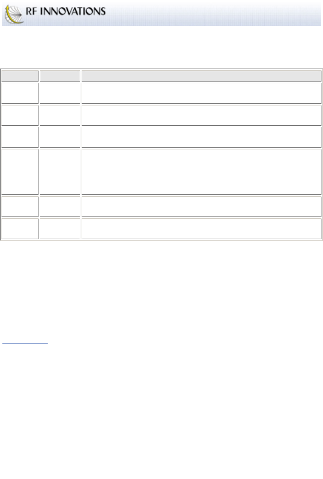
DATA PATH
Internally, the RFI-9256 stores a set of payload frames that are waiting to be transmitted, and a set of
payload frames that have been received but not yet processed. Combining this with the serial port interface
described in section 4, an overall picture of the data path in the RFI-9256 radio can be obtained. This is
shown for a master unit in Figure 4.
Operation
RFI-9256 Radio Modem User Manual Page 18 of 96
4kB output buffer
4kB input buffer outgoing frame buffers
incoming frame buffers
Frame 1
f
1
Frame 2
f
2
Frame Time
20ms
M M S S
Figure 4: Overall data path in the RFI-9256 radio
Due to the framing structure over the air, and the data path shown above, the RFI-9256 cannot be regarded
as a direct wire replacement. It will induce additional latency into the communications link, as well as
potentially causing changes in the timing between bytes (inter-character delay).
LATENCY
The RFI-9256 will introduce latency into the system. This latency is caused by the following factors:
Serialisation delays. Serialisation delays are caused by the time taken for the incoming RS-232
bit stream to be converted back into bytes. The serialisation delay for each serial port can be
calculated in milliseconds using Equation 1.
baud
bits
t
serial
1000=
Equation 1: Latency induced by serialisation delay for a single serial port in ms
Where bits is the number of bits in a byte (including start, stop and parity bits), and baud is the baud
rate of the serial port.
Thus, for 9,600 baud, 8N1 the serialisation delay is around 1ms per serial port.
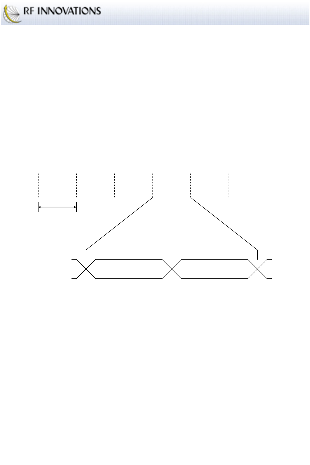
Framing delays.
Framing delays will occur depending on where data arrives relative to the start of
a frame. Consider the situation in Figure 5.
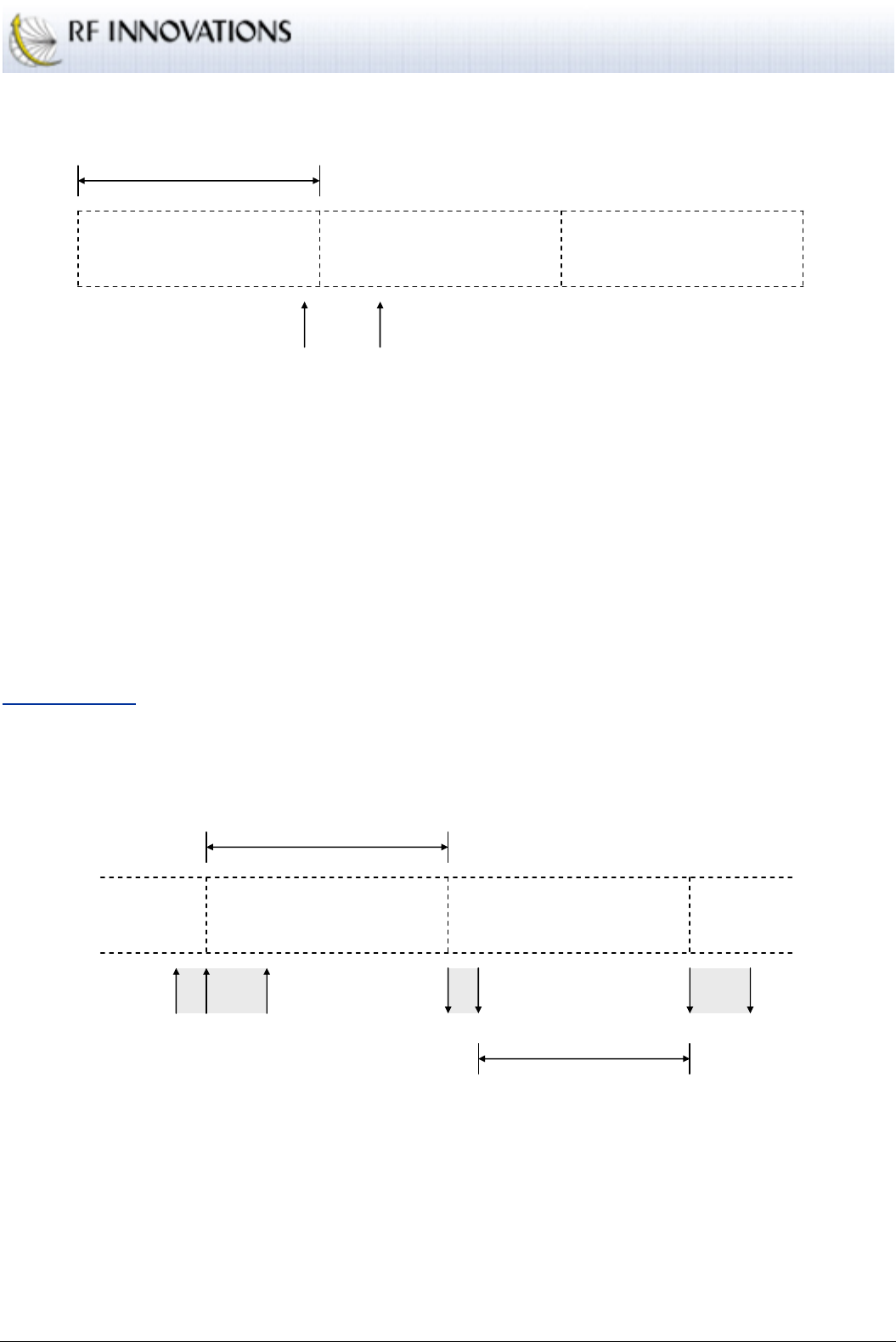
Operation
RFI-9256 Radio Modem User Manual Page 19 of 96
Frame 1
Frame 2
Frame 3
Frame Time
20ms
P1 P2
Figure 5: Data arriving at different times relative to the start of frame
The data arriving at P1 would be transmitted almost immediately in frame 2, while the data arriving
at P2 will have to wait until the start of the next frame. In the worst case, the amount of latency
introduced will be equal to the frame time.
Link quality.
The quality of a link can have a substantial impact on the latency induced by the
radio. The RFI-9256 will retry frames that become corrupted due to RF interference, configurable
between 0 and 50 retries. The more retries that are required to get a packet through the greater the
latency induced. Each retry adds an additional frame time to the latency induced by the radio.
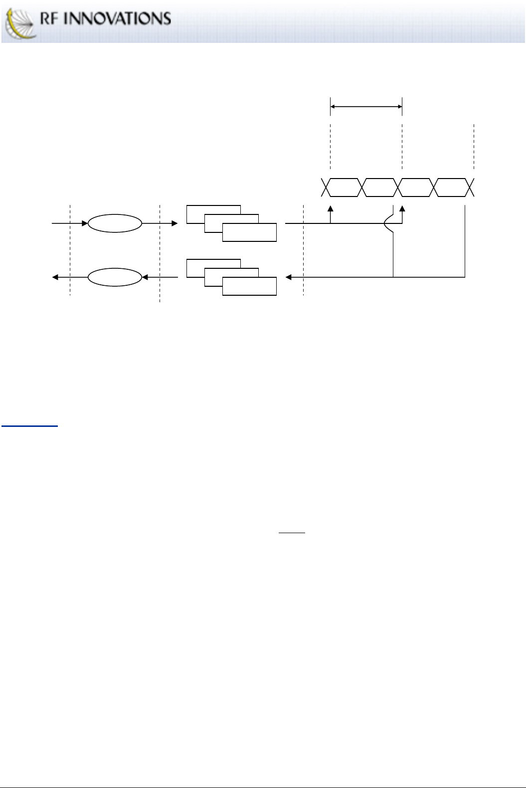
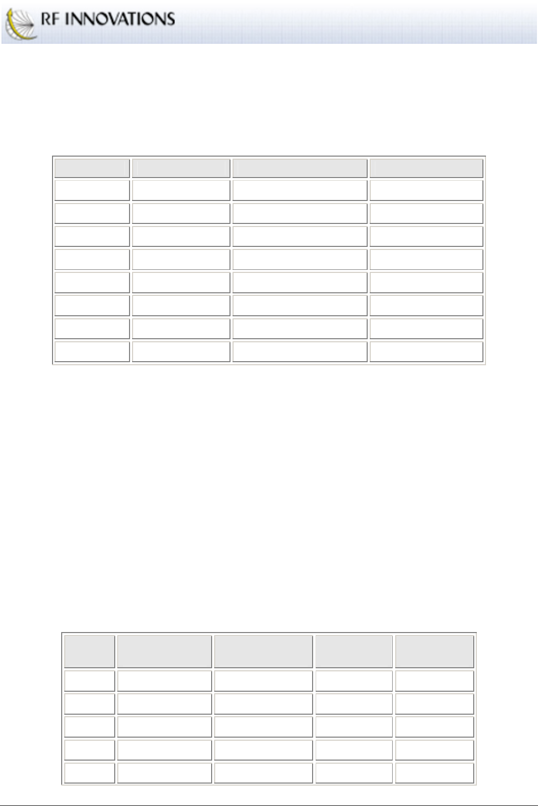
DATA TIMING
The RFI-9256 will change the inter-character and inter-packet timing of data that it transmits as all data
received by the RFI-9256 is framed for transmission over the air. Consider the situation shown in Figure 6.
Frame 1
Frame 2
Frame Time
20ms
P1 P3 P1 P2 P2 P2 P3
Inter-character Delay
Figure 6: Data timing variation due to framing
Data between P1 and P2 arrives before the start of Frame 1. This is then transmitted over the air, and is
output at the end of Frame 1. The data between P2 and P3 had to wait for frame 2 to be transmitted, so now
there is an artificial gap introduced between the bytes before P2 and after P2.
This problem can be exaggerated by additional retries occurring for frame 1 or frame 2.

Operation
RFI-9256 Radio Modem User Manual Page 20 of 96
In order to counteract this problem, packetisation timers, described in the section Time Based Packetisation
of Data on page 24.
4.2.2 Radio Parameters
ADDRESSING
Each radio in a RFI-9256 network has a local address. The local address is a decimal number between 1 and
9999.
When allocating addresses on an RFI-9256 network, the convention is to allocate the address 1000-9999 to
the master and slaves, while reserving the addresses 10-99 to be allocated to any back-to-back repeaters. In
general, addresses 1-9 are not used. The reason for this is explained in the section Back-to-back Repeater
Operation on page 23.
NETWORK FAIL TIMER
When power is first applied to a slave, it enters the unlocked state. In the unlocked state the slave has not
heard a master unit, and waits on a single channel listening for a master to hop past. When the master hops
past, the slave will start hopping with the master.
If the master loses power, or becomes unreachable, then the slave will continue to hop over the channels,
searching for the master. If after the network fail timer period expires the slave has failed to hear from its
master it reverts to the unlocked state.
TRANSMIT POWER
The transmit power of the RFI-9256 can be configured at fixed intervals 0dBm, +10dBm, +20dBm,
+25dBm, and +30dBm.
When operating in the 900MHz ISM band, the maximum allowed output power at the antenna is 1 Watt
effective isotropic radiated power (EIRP). This translates to +30dBm. Noting that cables will introduce loss,
and the antenna may introduce gain, the transmit power of the RFI-9256 should be adjusted so that the
power at the antenna is as close to +30dBm as possible.
RSSI TRIP LEVEL
The RFI-9256 supports a configurable RSSI trip level, or squelch. The RSSI trip level sets the lowest RSSI
that the RFI-9256 is to attempt to acquire data. When the radio has to operate in a very noisy environment,
where the background noise has risen above its sensitivity (-108 dBm), the RSSI trip level will need to be set
higher than the default to allow the radios to communicate.
When operating in a normal environment the RSSI trip level should be set below the radio’s sensitivity
otherwise the radio will be artificially deafened.
Operation
RFI-9256 Radio Modem User Manual Page 21 of 96
FRAME TIME
The frame time is the amount of time that the RFI-9256 will spend on each channel in the hopping pattern.
This is also referred to as the channel dwell time. The frame time can be adjusted to suite a particular
application. The set of values are shown in Table 7.
Frame Time Bytes per Packet Throughput (One Way) Throughput (Total)
5ms 5 8kbps 16kbps
8ms 26 26kbps 52kbps
10ms 41 32kbps 64kbps
15ms 77 41kbps 82kbps
20ms 113 45kbps 90kbps
25ms 149 48kbps 96kbps
30ms 185 49kbps 98kbps
35ms 221 51kbps 102kbps
Table 7: Frame time configuration
Selection of frame time will trade off maximum throughput against latency. A low frame time will decrease
both latency and throughput, while a high frame time will increase both latency and throughput. This is
discussed in the section Latency Reduction on page 24.
DIRECTIONAL BIAS
A single frame on the RFI-9256 contains two packets, one from the master and one from the slave. In the
default configuration the size of both packets is the same, so the system is unbiased. In many systems data
will flow in one direction substantially more than in the other direction. When this is the case the RFI-9256
can be configured to bias its frames so that the master packet and slave packet are of different lengths.
In order to configure a link for directional bias, one radio must be set to the outgoing radio, and one to the
incoming radio. The link from the outgoing radio to the incoming radio has more bandwidth, while the link
from the incoming radio to the outgoing radio has its bandwidth reduced.
Table 8 shows the different settings that can be obtained through directional bias.
Frame
Time
Outgoing Bytes
per Packet
Incoming Bytes
per Packet
Outgoing
Throughput
Incoming
Throughput
5ms 5 5 8kbps 8kbps
8ms 26 26 26kbps 26kbps
10ms 55 27 44kbps 22kbps
15ms 125 28 67kbps 15kbps
20ms 197 28 79kbps 11kbps

Operation
RFI-9256 Radio Modem User Manual Page 22 of 96
25ms 269 28 86kbps 9kbps
30ms 338 31 90kbps 8kbps
35ms 410 31 93kbps 7kbps
Table 8: Directional bias configuration for different frame times
RETRIES
The maximum number of retries per frame can be configured between 0 to 255. When a low number of
retries is selected, the link may become unreliable in the presence of interference. When a high number of
retries is selected the link will be reliable, however it may induce substantial latency in the presence of
interference.
If an RFI-9256 is given data to transmit to a slave that is non-existent, either due to a misconfigured
destination address, the slave being out of range, or the slave unit being faulty, then it will transmit each
frame the maximum number of retries. This can dramatically slow down the throughput of a radio network.
The RFI-9256 also supports exponential back-off and retry. This mechanism is intended for a situation
where there are multiple slaves that may have data to transmit at the same time. If these slaves are
configured with exponential back-off and retry mode enabled, collisions will have a minimal impact on
system performance.
SYNCHRONISATION
When two or more RFI-9256 are located in very close proximity, such as when they are in a back-to-back
repeater configuration, the transmitter from one can interfere with the receiver of the other even though they
are on different channels, simply due to the large amount of power that is being radiated.
In order to prevent this from happening it is desirable to synchronise the radios so that they will transmit at
the same time. Only master units can be synchronised in this way, as slave units must obtain their
synchronisation from the network master.
The frame synchronisation is a TTL I/O on the DB25 connector described in Appendix A.3.
Each RFI-9256 can be configured with one of the following synchronisation options:
No Sync Mode
: Disables synchronisation.
Output Sync Signal
: The radio will output a frame synchronisation signal. This is a falling edge
on the TTL output every time a new frame starts.
Follow Sync Signal
: The master radio will follow the synchronisation signal output by another
unit. This causes the master radio to adjust the start of its frame to match the falling edge detected
on the synchronisation TTL input. This mode should be used when a master is following another
collocated master.
Repeater Sync Mode
: The master radio will follow the synchronisation signal output by another
unit. This causes the master radio to adjust the start of its frame to be 50% offset from the falling
Operation
RFI-9256 Radio Modem User Manual Page 23 of 96
edge detected on the synchronisation TTL input. This mode should be used when a master is
following a collocated slave, such as when they are in back-to-back repeater configuration.
Synchronisation does not operate correctly when directional bias has been enabled on either unit.
MASTER / SLAVE CONFIGURATION
A network of RFI-9256 radio radios will consist of one master, and one or more slaves. Multiple co-located
masters are supported in the RFI-9256 system through three mechanisms:
Hopping Pattern.
Each master unit has a unique hopping pattern. The hopping pattern determines
the order that the master hops over all available channels. There are 32 available hopping patterns,
and these have been selected so as to cause minimum interference between co-located masters.
Network Address.
The network address is a number between 0 and 63 that defines the network to
which the master belongs. The network address provides a second layer of differentiation between
multiple masters.
Security Code.
Each RFI-9256 can be programmed with a 32-bit security code. A slave will only
be able to communicate with a master if both units have the same security code.
The master and all the slaves in a single network must be configured with the same values for hopping
pattern, network address, and security code.
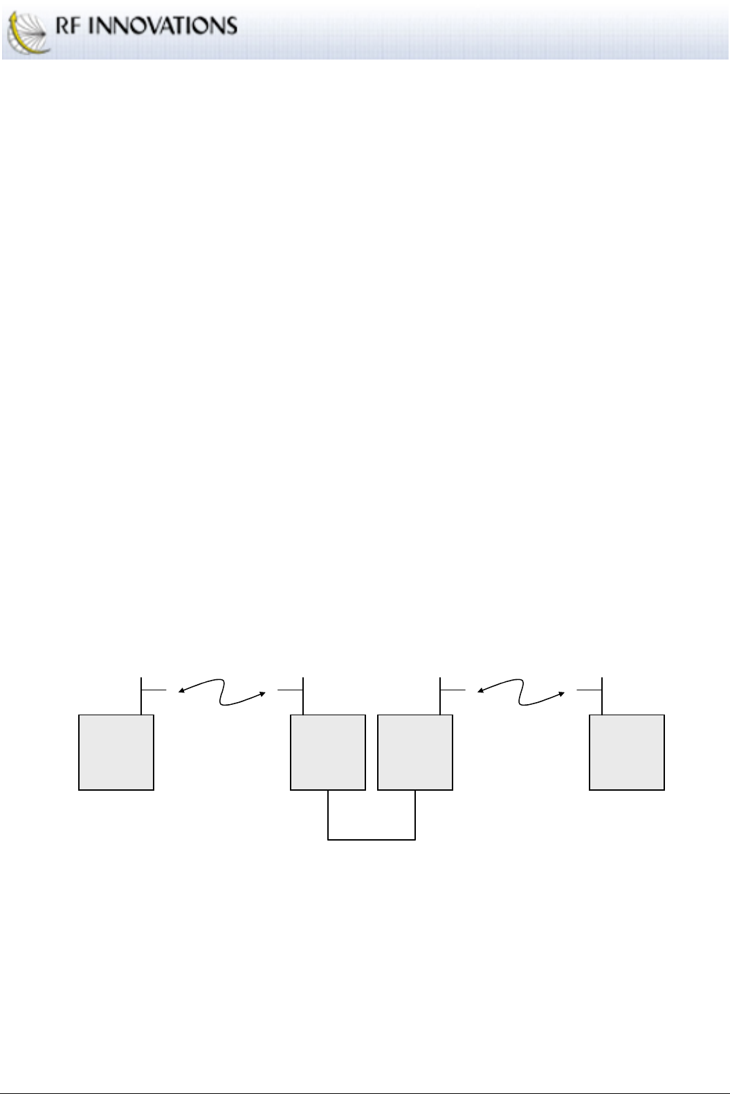
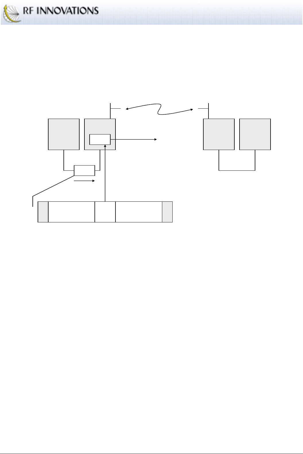
BACK-TO-BACK REPEATER OPERATION
The RFI-9256 supports network extension through the use of a back-to-back repeater. A back-to-back
repeater consists of two RFI-9256 radio radios. This is shown in Figure 7.
RFI
-
9256
Master 1
HPSN=0
Addr=1000
RFI
-
9256
Slave 1
HPSN=0
Addr=20
RFI
-
9256
Master 2
HPSN=1
Addr=20
RFI
-
9256
Slave 2
HPSN=1
Addr=3000
Wiring
Harness
Figure 7: Back-to-back repeater configuration
A back-to-back repeater configuration is the joining two separate RFI-9256 networks via a wiring harness
between a slave on one network and the master of a second network. The wiring harness can link the main
port, auxiliary port, or both ports via a null-modem cable. A wiring diagram for a back-to-back repeater
cable that links both main, auxiliary, and the auxiliary I/O lines is given in Appendix A.4.
When setting up back-to-back repeaters, the following rules should be followed:

Operation
RFI-9256 Radio Modem User Manual Page 24 of 96
•
Both master and slave radio must have the same local address, and it must be in the range 10-99 (i.e.,
two characters).
•
All other radios in the network must have local addresses in the range 1000-9999.
These rules come about due to the way Hayes dial-up works in a back-to-back repeater network. See section
4.3.3 for more information on Hayes dial-up networking.
Back-to-back repeaters should be synchronised, as discussed in the section Synchronisation on page 22, in
order to prevent them from jamming each other due to collocated antennas.
The slave must be configured to output a synchronisation signal.
The master must be configured to follow a repeater synchronisation signal.
This guarantees that both master and slave will transmit at the same time.
4.2.3 Performance Tuning
LATENCY REDUCTION
Some systems will require a radio link that induces very low latency, usually where the RFI-9256 is being
used to replace an existing wired system. There are a number of parameters that can be traded off in order to
reduce latency.
Throughput.
The throughput of the RFI-9256 can be reduced, with a corresponding reduction in
latency. This is achieved by reducing the frame time as the frame time has a direct impact on
latency. A smaller frame time will give lower latency. See section Latency on page 18 for a
discussion on why this is the case.
Reliability.
By reducing the maximum number of retries the latency performance of the RFI-9256
can be improved in harsh RF environments. Given that each retry will add an extra frame time to
the latency induced by the radio, calculate the maximum acceptable latency induced by retries, and
divide by the frame time to give the maximum retries that should be configured. Note that by
reducing the maximum number of retries, data may be lost so the underlying system should be
robust enough to handle this situation.
TIME BASED PACKETISATION OF DATA
Many protocols delimit packets of data by silence on the communications line for a set period of time. A
common example of such a protocol is Modbus.
Due to the TDD nature of the RFI-9256, simply passing this data into the radio can cause it to become
disrupted as there is no guarantee that timing will be maintained over the air link (see section Data Timing
on page 19). In order to correct this problem, two configuration items should be used.
Set the RX packetisation timer to the number of milliseconds that will appear between each
packet.
Operation
RFI-9256 Radio Modem User Manual Page 25 of 96
Set the frame time to the smallest number that will provide enough bytes in a single frame for the
largest protocol message.
The packetisation time is used to detect the end of each packet. Only once the end of the packet has been
detected will the RFI-9256 transmit any of the packet.
The frame time must be configured to allow a full packet in a single frame, as if the frame time is too small
then the packet will be split across multiple frames and inter-character delay could occur due to retries.
When packets are larger than the maximum frame time, yet must still be kept together the TX packetisation
timer can be used. This timer operates in the same way as the RX packetisation timer, except that it will
attempt to bunch received data frames together. When the TX packetisation timer is enabled the radio will
not transmit data out of its serial port until an amount of time equal to the packetisation timer has passed
with it receiving no data over the air.
4.2.4 Diagnostics
RSSI AND NOISE
The RFI-9256 can report the RSSI and noise detected on each individual channel in the 900MHz ISM band.
This is accessed through the diagnostics menu (Appendix B.6).
There are two factors to be aware of when using the RSSI / Noise report of the RFI-9256.
1.
The master is transmitting all the time, while slaves only transmit when they have data or a
connection has been established to them. Thus, a slave will always be able to report the RSSI of the
master, while the master can only report slave RSSI when communications is occurring.
2.
Each individual slave can only hear the master unit, while the master can hear all the slaves. This
means that when a master is communicating with multiple slaves there is no guarantee which slave
the RSSI value refers two, in fact it is most likely to be an average of all slaves. In order to counteract
this effect a special link margin test is provided on the master unit. The link margin test will take
control of the communications link and determine the exact RSSI that the master is receiving from a
particular slave. This is covered in Appendix B.6.
RF COMMUNICATIONS STATISTICS
The RFI-9256 provides a number of communications statistics that can be used to debug a RFI-9256 system.
These parameters are shown in Table 9.
Statistic Description
Frame
count The total number of frames that have passed while the radio has been operating.
Empty
frames The number of frames that have been received but contained no user data.
Good
packets The number of good packets received.
Operation
RFI-9256 Radio Modem User Manual Page 26 of 96
Bad
packets The number of bad packets received.
Lost
packets The number of packets that have been lost.
Retries The number of retries this unit has used while transmitting.
Good
headers The number of good header packets received. Header packets contain synchronisation and
control information.
Bad
headers The number of bad header packets received.
Lost frame
lock The number of times this unit has lost lock. A loss of lock occurs on a slave when it can no
longer hear the synchronisation messages from the master.
Low RSSI The number of times the RSSI level has been at or below the nominal sensitivity of the
radio while receiving.
Data Recv The number of user data bytes received.
Data Sent The number of user data bytes transmitted.
Rx
Overflows The number of times received data has been discarded due to there be no free frame buffers.
Rx
Overruns The number of times data has been lost due to internal radio errors.
Tx
Overflows The number of times an attempt has been made to obtain a frame buffer for transmission,
and there have been no free frame buffers.
Busy
Waits The number of times the slave radio has had data to transmit, but has been unable to do so
due to communications between the master unit and another slave radio.
Table 9: RF communications statistics
4.3 Protocol Operation
The protocol mode of a serial port determines how the serial port data is interpreted and converted into
packets for transmission over the air. There are four basic protocol modes:
Point-to-point Protocol
: Communications occurs between two radios only.
Broadcast Protocol
: Communications occurs between the master and any number of slaves, and
any slave back to the master. Data is broadcast from the master to all slaves, while the slave only
transmits data directly back to the master.
Hayes Dial-up Protocol
: Communications occurs between a master and any number of slaves one
at a time, where Hayes dialling commands are used to create and destroy connections.
SCADA Protocols
: Communications occurs using SCADA communications protocols such as
Modbus, Honeywell, DNP3, or TDE.

Operation
RFI-9256 Radio Modem User Manual Page 27 of 96
All protocol modes support back-to-back repeaters for extending network coverage.
4.3.1 Point-to-point Protocol
A point-to-point network establishes a link between two radio radios, through an optional number of
repeaters. A point-to-point connection can be established on the main, auxiliary, or both serial ports.
A single master unit and a single slave unit are configured such that:
The have the same hopping pattern, network address, and security code.
The master and slave have different local addresses.
Both the master and slave have the point-to-point protocol selected on their main serial port.
The point-to-point destination address on the slave is set to the master’s local address, while the
point-to-point destination address on the master is set to the slave’s local address.
This results in a connection being established between the two units. The online LED should turn green on
both units, and data transmitted by the DTE on the master be received on the DTE on the slave, and vice
versa.
4.3.2 Broadcast Protocol
In a point-to-multipoint broadcast network, data transmitted by the master unit is output by all the slaves,
while data transmitted by each slave is only output by the master.
When using point-to-multipoint broadcast mode, there are no acknowledgments on the master to slave
transactions. This is because multiple slaves may be receiving the data, and if they were to all attempt to
acknowledge the transmission they would interfere with each other.
Instead of acknowledgements, the master will transmit each message a fixed number of times equal to the
maximum retries. For this reason, the number of retries used in a broadcast network should be configured to
between 1 and 5 in order to maintain a reasonable throughput.
4.3.3 Hayes Dial-up Protocol
Hayes dial-up networks provide connection mechanism that emulates a PSTN modem’s dialling mechanism.
This is a more powerful method of operating than using point-to-point or point-to-multipoint broadcast
networks, as it allows dedicated communication between a master and one of many slaves.
CONNECTION MANAGEMENT
DIALLING
The AT commands may be used to initiate dialling of a remote radio. The
ATD
command is use to establish a
connection. The form of the
ATD
command is:
ATD<address><extension>
Operation
RFI-9256 Radio Modem User Manual Page 28 of 96
Where
<address>
is the address of the radio that is being dialled, and
<extension>
is the serial port or
internal extension port that is being dialled. The available extension numbers are shown in Table 10.
Extension Name Description
00 Main Port Establishes a connection between the current serial port and the main port on
the remote unit,
01 Auxiliary
Port Establishes a connection between the current serial port and the auxiliary port
on the remote unit,
91 Virtual
Hayes Establishes a connection between the current serial port and the Hayes
command interface running on the remote unit.
92 Remote
Menu
Establishes a connection between the current serial port and the menu of the
remote unit. When connection to a menu system remotely, the radio
configuration menu (Appendix B.1) will not be available. This is done to
prevent configuration changes that could sever the connection to the remote
radio.
93 Remote
Logger Establishes a connection between the current serial port and the logs of the
remote unit.
99 Loop-back Establishes a connection that loops back all data that is transmitted to the
remote unit.
Table 10: Hayes dial-up extension numbers
The
<address>
and
<extension>
sections of the ATD command can include any number of colons,
dashes, or spaces as these will be stripped out of the string by the radio.
If the radio receives a character on the serial port while dialling is in progress it will immediately terminate
the connection attempt and send a
NO CARRIER
response message.
If a connection is established then the
CONNECT
response message will be returned.
ANSWERING
The RFI-9256 provides two options for answering dial-up calls:
Auto-answer
. When in auto answer mode and a connection request is made the RFI-9256 will
output a configurable number of
RING
responses on the destination radio and extension, and then
automatically connected. When dialling an extension other then the main or auxiliary port, auto-
answer is used by default.
Manual answer
. When in manual answer mode the RFI-9256 will output a
RING
response on the
destination once per second until the
ATA
command is received at which point the connection is
established. If no
ATA
command is received within the connect timeout the connection is not
established.

Operation
RFI-9256 Radio Modem User Manual Page 29 of 96
Manual answering of dial-up requests only applies to the main and auxiliary ports. The internal extension
numbers for the virtual Hayes, remote menu, remote logger, and loop-back services will always answer
automatically.

Operation
RFI-9256 Radio Modem User Manual Page 30 of 96
ESCAPE SEQUENCE
When there is no communications link established to a remote radio, and AT commands are issued locally
then the radio is in local command state.
When a connection is established to a remote radio, all communications occurs between the DTE’s
connected to the ports on the two radios. This is known as online state. Once a radio enters online state, it
assumes all the data sent to it is to be sent on to the remote radio, so it ignores all AT commands.
Unlike the other commands, there is no AT prefixing the escape sequence, and no carriage return after the
escape sequence. Instead, wait a full second before entering the three characters (default is ‘+’) typed
rapidly, then wait another full second. As soon as the radio returns to local command state, it will respond
with the message
OK
.
This delay period before and after the escape sequence is called the escape sequence guard time. This allows
the radio to distinguish the escape sequence from the normal flow of user information between radios.
The character used for the escape sequence is set in s-register 2, while the length of the escape guard time is
set in s-register 12.
When entering local command state, the connection is not disrupted. In order to return back to online state,
the command
ATO
is used.
HANGING UP
The
ATH
command is used to terminate a connection.
After communications has finished enter the escape sequence (+++). The radio responds with an
OK
message. Then execute the
ATH
command and the local radio will respond with
OK
. The remote radio will
output
NO CARRIER
as the communications link is lost.
DTR CONTROL OF HAYES STATE
The Data Terminal Ready (DTR) input to the radio can be used to control the Hayes dial-up state.
Ignore DTR:
The radio does not use the DTR signal to control its connection state.
Hang-up on DTR Low:
The radio will hang-up whenever the DTR line is low. If this option is
selected, and DTR is low when a remote radio is dialled then the connection will be terminated the
moment after it is established.
Hang-up on DTR Dropped:
The radio will hang-up whenever DTR changes from high to low.
Local on DTR Low:
Whenever DTR goes low, the radio will enter local command state. This is
the same as entering the escape sequence.
DIAL-UP NETWORKING WITH BACK-TO-BACK REPEATERS
A Hayes dial-up network can be extended by one or more back-to-back repeaters. In order to establish a dial-
up connection through a back-to-back repeater, an extension to the dialling system is used:
ATD<repeater
0
><repeater
1
>...<repeater
n
><address><extension><CR>

Operation
RFI-9256 Radio Modem User Manual Page 31 of 96
The address of each repeater to dial through is prefixed before the address of the destination radio and
extension. Thus to dial the auxiliary port of the radio with address 2200 first through repeater 10 and then
through repeater 43 the following dial string would be used:
ATD1043220001<CR>
In order to access the repeater slave’s terminal menu, dial up the menu system as if it were any other slave.
In order to access the repeater master’s terminal menu dial up the main port of the slave (the port that has
been connected through to the master unit), then use the master units AT command interface to bring up the
menu system via the
AT?
command.
When using back-to-back repeaters in dial-up networks, there are a number of rules that must be observed:
The escape character on the repeater master and repeater slave must be set to ‘-‘.
The escape guard time on the repeater master and repeater slave must be set to 200ms.
The main port DTR mode on both the repeater master and repeater slave must be set to “Hang-up
on DTR dropped”.
The local address of the repeater slave and repeater master must both be the same, and must both
be in the range 10-99.
The local address of all non-repeater units must be in the range 1000-9999.
The DTR line is used in the back-to-back repeater wiring harness in order to propagate Hayes hang-up
requests through the network. If this line is not connected there is a possibility that the hang-up request could
get lost and the repeater network lock-up, believing there to be an established connection.
For this reason it is not advised to use dial-up networking through back-to-back repeaters on the auxiliary
port.
4.3.4 SCADA Protocols
The RFI-9256 supports SCADA protocol networks in two ways:
Providing a point-to-multipoint broadcast network, where any SCADA packet that is inserted at
the master will be delivered to all slaves, and a SCADA packet inserted into any slave is delivered
to the master. This was covered in section 4.3.2.
Providing a point-to-multipoint routing network, where master to slave communications is no
longer broadcast. In this case the RFI-9256 will decode each SCADA protocol packet to extract
the destination address and match it against a radio address.
Routing services are provided for a number of SCADA protocols, specifically:
Modbus
Honeywell
DNP3
Operation
RFI-9256 Radio Modem User Manual Page 32 of 96
TDE
PROTOCOL ROUTING
The protocol decoder for the packet based SCADA protocols extracts the destination remote terminal unit
(RTU) address from the protocol and maps it to a radio address. This routing scheme is shown in Figure 8.
Controller
RFI
-
9256
Master
Main
RFI
-
9256
Slave
Addr=1000
RTU
Main
SCADA Data Address
SCADA Data Pad
Pad
Table
SCADA
Address
Slave Address
Figure 8: SCADA protocol routing
The SCADA protocol routing table on the RFI-9256 can have four types of entries.
Default route.
This route is mostly used by slaves and is a required entry for any slave in a
protocol network. This route only requires the address of the destination radio. This route is used
when no other route can be matched in the routing table. On slave units this destination address
must always be the address of the master unit.
Single route.
This route explicitly maps a single RTU address to a radio address. If a single route
exists, then it overrides any matching mapped route or range route.
Mapped route.
This route maps a relationship between RTU addresses and radio addresses. This
is an efficient method of describing a network providing the RTUs and radios are numbered
sequentially. This route configuration requires an RTU address to be assigned as the base for the
route and an RTU address to define the range of addresses to be used by the route. It also requires
a radio address associated with the base RTU address.
The decoder subtracts the RTU base address from each decoded RTU address. This result is then
added to the radio base address. Consider the situation shown in Figure 9.
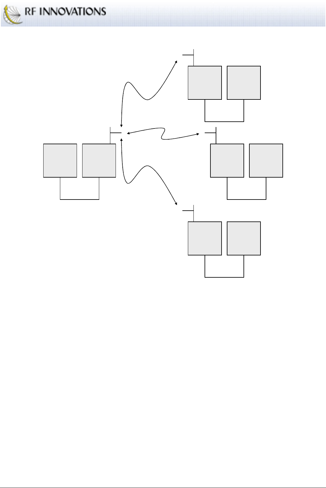
Operation
RFI-9256 Radio Modem User Manual Page 33 of 96
Controller
RFI
-
9256
Master
Main
RFI
-
9256
Slave
Addr=1000
RTU
20
Main
RFI
-
9256
Slave
Addr=1001
RTU
21
Main
RFI
-
9256
Slave
Addr=1002
RTU
22
Main
Figure 9: Range routing relationship between radio address and RTU address
The base RTU address is 20 and the range is 22. The base radio address is 1000 . When the
decoder finds RTU address 21 it subtracts it from the base RTU, leaving a result of 1. This is then
added to the base radio address giving a radio address of 1001 which has RTU 21 attached.
Range route.
This route mode routes any RTU address between a start and end RTU address to a
single radio address.
4.3.5 Mixed Protocol Networks
The RFI-9256 offers dual independent serial ports that can be used for different network configurations. This
allows for any combination of the following network configurations to co-exist in a single radio network.
Point-to-point configurations.
Point-to-multipoint broadcast configurations.
Hayes dial-up configurations.
SCADA protocol configurations.

Operation
RFI-9256 Radio Modem User Manual Page 34 of 96
The most common use for this co-existence is to allow remote monitoring of radios without disrupting the
main data path through the network. This is achieved by configuring the main data path on the main port,
and leaving the auxiliary port on the master unit for Hayes dial-up. Hayes commands can then be used to
connect to the terminal menu of each individual radio in the network.
4.3.6 Network Link and Online Determination
There are two important indications given by the RFI-9256 as to the current network status, network link and
online. These two parameters have different functionality when running in point-to-point, point-to-
multipoint broadcast, Hayes dial-up, and SCADA routing modes as shown in Table 11.
Mode Network Link on Master Online (both Master and Slave)
Point-to-
point
Comes on whenever a point-to-point
connection is established with a
slave, and is turned off when the
point-to-point connection is closed.
In turning off it waits for 3 * network
link timeout ms.
While there is no point-to-point link established, the
LED is off. Once the point-to-point link is
established the LED is set on (green).
If connection is severed, both units will flash the
Online light red every time a packet is dropped due
to running out of retries. This will happen once per
online request poll (defaults to 3 seconds). Once the
network link light is turned red, the online light will
be turned off.
Point-to-
multipoint
Broadcast
Turns green whenever data is
received. Turns off again after no
data has been received for 3 *
network link timeout ms.
Turns green whenever data is received. Turns off
after a short period with no data.
Hayes
Dial-up
Comes on whenever a dial-up
connection is established with the
slave, is turned off when the dial-up
connection is closed. In turning off it
waits for 3 * network link timeout
ms.
While there is no dial-up connection, the LED is off.
Once the dial-up connection is established, the LED
is set on (green).
If connection is severed, the dialler (source of the
connection) will flash the Online light red every
time a packet is dropped due to running out of
retries. This will happen (in the absence of data)
once per online request poll. Once the network link
LED is turned red, the online light will turn black.
The receiver (destination) will turn its online light
off immediately upon losing the first online request
from the dialler.
SCADA
protocol
networks
Turns green whenever data is
received. Turns off again after no
data has been received for 3 *
network link timeout ms.
Turns green whenever data is received. Turns off
after a short period with no data.
Table 11: Network link and online functionality in different protocol modes

Operation
RFI-9256 Radio Modem User Manual Page 35 of 96
Network link always functions the same way on the slave unit, regardless of protocol mode. On a slave
network link comes on whenever the slave has successfully locked with a master radio and is hopping with
it. It will be turned off after the time specified 2 * network link timeout (ms) passes without the slave
receiving its master's transmission.
When a serial port output (DCD or CTS) has been configured to follow online or follow network link, the
output will be high so long as online or network link is red or green. Once online or network link goes black
the serial port output will go low.
4.4 Auxiliary I/O
The RFI-9256 supplies 8 auxiliary digital I/Os (+5V TTL) that can be mirrored across a radio network. Each
digital I/O can be individually configured as an input or output, and digital outputs can have a default state
when power is applied before a connection is established to a remote radio (see appendix B.4.2 for details).
4.4.1 Input Sampling
All digital inputs are sampled at a fixed interval that may also be configured. The smaller the sample interval
the faster changes will be propagated across the radio network. However if a lot of changes occur to the
digital I/Os in rapid succession this can generate a large amount of traffic that may adversely affect serial
port data throughput.
4.4.2 I/O Routing
I/Os are routed transparently on point-to-point or Hayes dial-up links. When a point-to-point link is used and
remote I/O is enabled, each output on a unit will be set to the current state of the input on the other unit. For
this reason it is important to ensure that the outputs on one unit are matched with inputs on the other unit.
When Hayes dial-up is used, the I/Os will be mirrored so long as a connection is established. When the
connection is closed the I/Os will be held at the last known value.
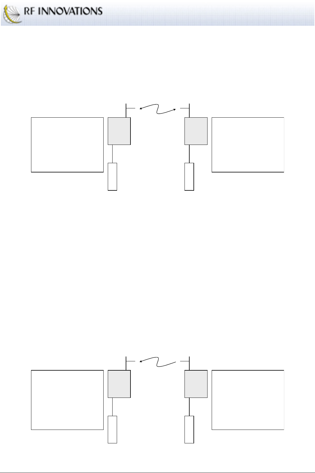
Applications
RFI-9256 Radio Modem User Manual Page 36 of 96
5. Applications
5.1 Basic Point-to-point Network
A basic point to point network is shown in Figure 10.
RFI-9256
Master RFI-9256
Slave
Main
DTE
Main
DTE
RADIO CONFIGURATION
Unit is a SLAVE
Network Address: 12
Hopping Pattern: 4
Rx Address: 2000
PROTOCOL CONFIGURATION
Main Port: Point-to-point to 1000
SERIAL CONFIGURATION
Main Port: 115200, 8N1, Hardware Flow
RADIO CONFIGURATION
Unit is a MASTER
Network Address: 12
Hopping Pattern: 4
Rx Address: 1000
PROTOCOL CONFIGURATION
Main Port: Point-to-point to 2000
SERIAL CONFIGURATION
Main Port: 115200, 8N1, Hardware Flow
Figure 10: Basic point-to-point network
A single master unit and a single slave unit are configured such that:
The have the same hopping pattern, network address, and security code.
The master and slave have different local addresses.
Both the master and slave have the point-to-point protocol selected on their main serial port.
The point-to-point destination address on the slave is set to the master’s local address, while the
point-to-point destination address on the master is set to the slave’s local address.
5.2 Simplex Point-to-point Network
A simplex point-to-point network is the same as a basic point-to-point network, except that user data is only
going to flow in a single direction. This situation is shown in Figure 11, where user data is only flowing
from the slave to the master unit.
RFI-9256
Master RFI-9256
Slave
Main
DTE
Main
DTE
RADIO CONFIGURATION
Unit is a SLAVE
Network Address: 21
Hopping Pattern: 7
Rx Address: 2000
Directional Bias: Outgoing
PROTOCOL CONFIGURATION
Main Port: Point-to-point to 1000
SERIAL CONFIGURATION
Main Port: 115200, 8N1, Hardware Flow
RADIO CONFIGURATION
Unit is a MASTER
Network Address: 21
Hopping Pattern: 7
Rx Address: 1000
Directional Bias: Incoming
PROTOCOL CONFIGURATION
Main Port: Point-to-point to 2000
SERIAL CONFIGURATION
Main Port: 115200, 8N1, Hardware Flow
Figure 11: Simplex point-to-point network
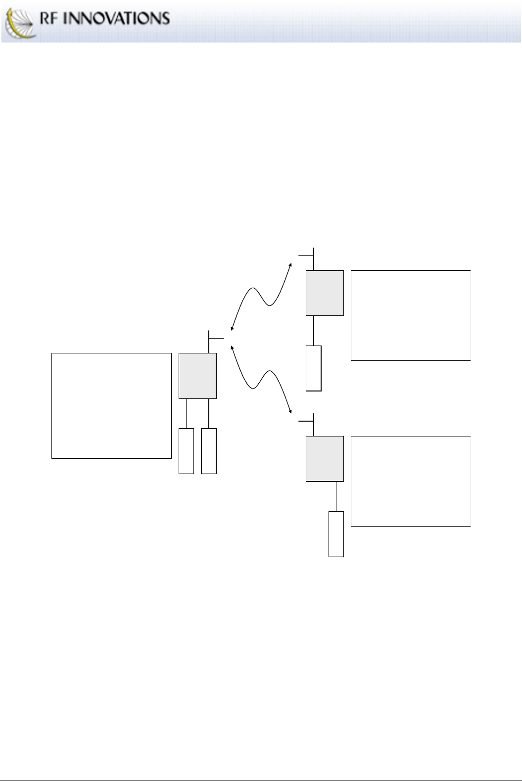
Applications
RFI-9256 Radio Modem User Manual Page 37 of 96
Even though user data is only flowing in one direction, there is data being transmitted from the master to the
slave in the form of acknowledgments for each packet received.
The simplex point-to-point network has the same configuration as the basic point-to-point network, except
that now the slave is configured with an outgoing directional bias and the master is configured with an
incoming directional bias.
5.3 Multiple Slave Point-to-point Network
The multiple slave point-to-point network can be expanded to allow two slave units to be connected to a
single master using point-to-point links. This configuration is shown in Figure 12.
RFI-9256
Master
RFI-9256
Slave 1
Main
DTE
Main
DTE
RADIO CONFIGURATION
Unit is a SLAVE
Network Address: 54
Hopping Pattern: 18
Rx Address: 2000
PROTOCOL CONFIGURATION
Main Port: Point-to-point to 2000
SERIAL CONFIGURATION
Main Port: 115200, 8N1, Hardware Flow
RADIO CONFIGURATION
Unit is a MASTER
Network Address: 54
Hopping Pattern: 18
Rx Address: 1000
PROTOCOL CONFIGURATION
Main Port: Point-to-point to 2000
Aux Port: Point-to-point to 3000
SERIAL CONFIGURATION
Main Port: 115200, 8N1, Hardware Flow
Aux Port: 9600, 8N1, No Flow
RFI-9256
Slave 2
Aux
DTE
RADIO CONFIGURATION
Unit is a SLAVE
Network Address: 54
Hopping Pattern: 18
Rx Address: 3000
PROTOCOL CONFIGURATION
Aux Port: Point-to-point to 1000
SERIAL CONFIGURATION
Aux Port: 9600, 8N1, No Flow
Aux
DTE
Figure 12: Multiple slave point-to-point network
In this scenario, the radios are configured in the same way as for the basic point-to-point network, however
now the auxiliary port must be configured in point-to-point mode and given the destination address as the
address of slave 2. This allows all data transmitted on DTE1 on the master to be received by DTE1 on slave
1, and vice versa. At the same time all data transmitted by DTE2 on the master will appear at DTE2 on slave
2 and vice versa.
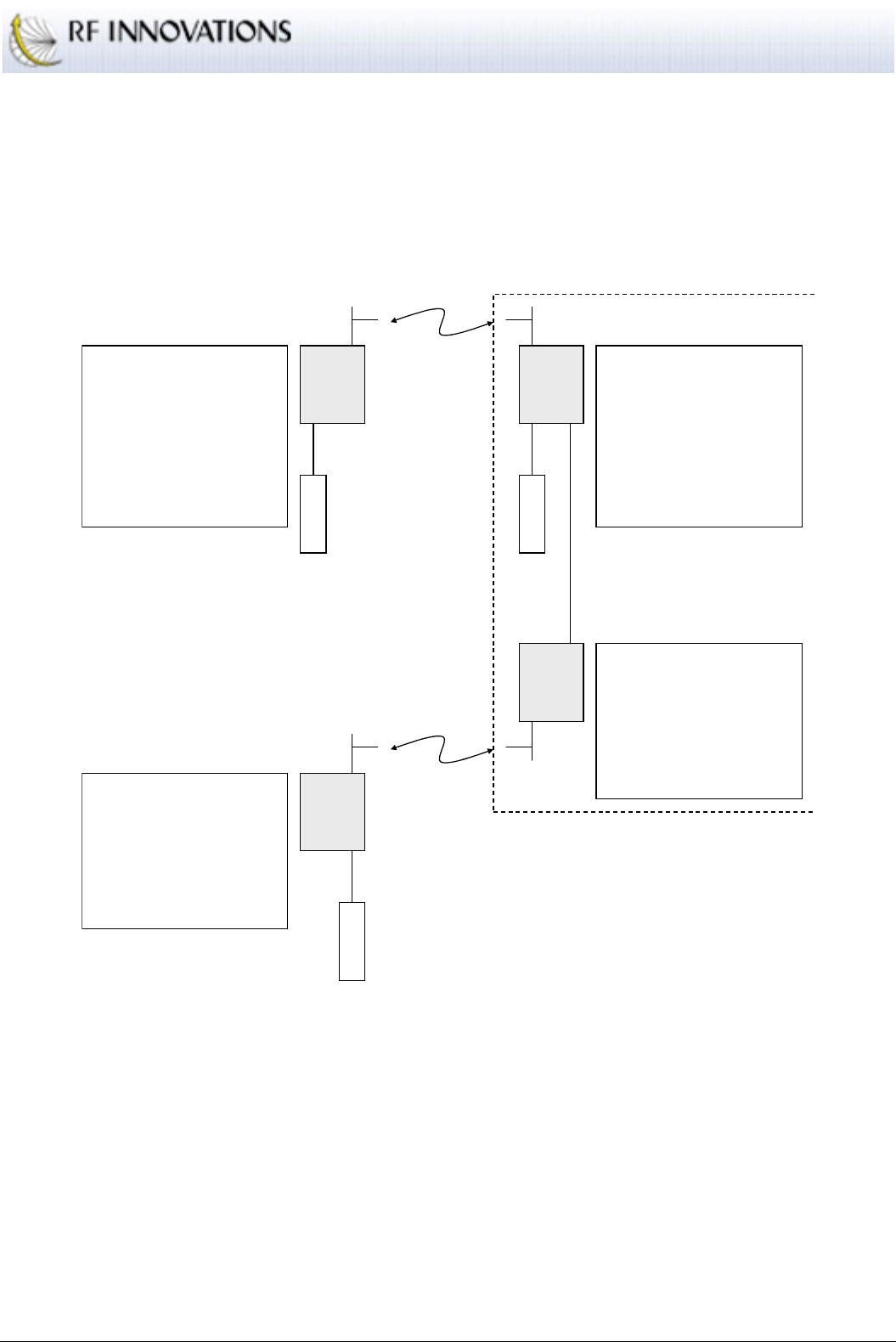
Applications
RFI-9256 Radio Modem User Manual Page 38 of 96
5.4 Point-to-point Network with Back-to-back Repeaters
The final point-to-point configuration involves the addition of one or more back-to-back repeaters. Back-to-
back repeaters can be used to extend the range of an RFI-9256 based network.
The basic network set-up for back-to-back repeaters in point-to-point links is shown in Figure 13.
RFI-9256
Master RFI-9256
Repeater
Slave
Main
DTE
Main
DTE
RADIO CONFIGURATION
Unit is a SLAVE
Network Address: 1
Hopping Pattern: 20
Rx Address: 20
PROTOCOL CONFIGURATION
Main Port: Point-to-point to 1000
Aux Port: Point-to-point to 1000
SERIAL CONFIGURATION
Main Port: 115200, 8N1, Hardware Flow
Aux Port: 115200, 8N1, No Flow
RADIO CONFIGURATION
Unit is a MASTER
Network Address: 1
Hopping Pattern: 20
Rx Address: 1000
PROTOCOL CONFIGURATION
Main Port: Point-to-point to 20
Aux Port: Point-to-point to 20
SERIAL CONFIGURATION
Main Port: 115200, 8N1, Hardware Flow
Aux Port: 115200, 8N1, No Flow
RFI-9256
Repeater
Master
RFI-9256
Slave
Aux
DTE
RADIO CONFIGURATION
Unit is a SLAVE
Network Address: 1
Hopping Pattern: 30
Rx Address: 3000
PROTOCOL CONFIGURATION
Aux Port: Point-to-point to 20
SERIAL CONFIGURATION
Aux Port: 115200, 8N1, No Flow
Aux Null Modem Cable
Back-to-back Repeater
RADIO CONFIGURATION
Unit is a MASTER
Network Address: 1
Hopping Pattern: 30
Rx Address: 20
PROTOCOL CONFIGURATION
Aux Port: Point-to-point to 3000
SERIAL CONFIGURATION
Aux Port: 115200, 8N1, No Flow
Figure 13: Point-to-point network with a back-to-back repeater
In this scenario, the master 1 and slave 1 form the first network. A point-to-point connection is established
between both main and auxiliary ports of these two units. Data transmitted by DTE1 on master 1 will be
received on DTE1 of slave 1. Data transmitted by DTE2 on the master will be received by slave 1, and
passed to master 2 via a null modem cable linking the two auxiliary ports. This data is then re-transmitted to
slave 2, which outputs the received data on its auxiliary port.
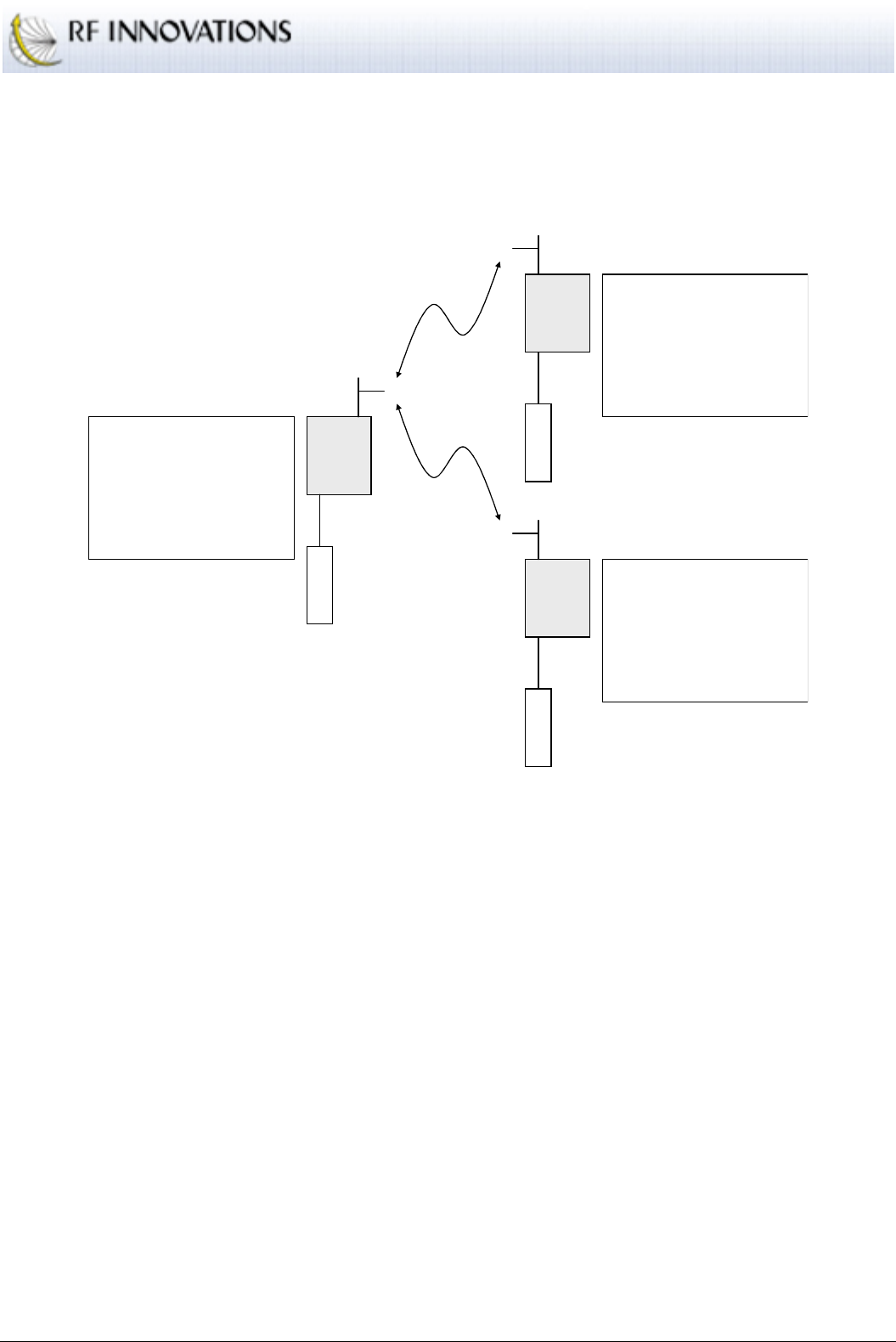
Applications
RFI-9256 Radio Modem User Manual Page 39 of 96
5.5 Broadcast Network
The basic configuration for point-to-multipoint broadcast networks is shown in Figure 14.
RFI-9256
Master
RFI-9256
Slave 1
Main
DTE
Main
DTE
RADIO CONFIGURATION
Unit is a MASTER
Network Address: 16
Hopping Pattern: 27
PROTOCOL CONFIGURATION
Main Port: Broadcast
SERIAL CONFIGURATION
Main Port: 115200, 8N1, Hardware Flow
RFI-9256
Slave 2
Main
DTE
RADIO CONFIGURATION
Unit is a SLAVE
Network Address: 16
Hopping Pattern: 27
PROTOCOL CONFIGURATION
Main Port: Broadcast
SERIAL CONFIGURATION
Main Port: 115200, 8N1, Hardware Flow
RADIO CONFIGURATION
Unit is a SLAVE
Network Address: 16
Hopping Pattern: 27
PROTOCOL CONFIGURATION
Main Port: Broadcast
SERIAL CONFIGURATION
Main Port: 115200, 8N1, Hardware Flow
Figure 14: Broadcast network
The master and all the slaves must be configured such that:
They have the same hopping pattern, network address, and security code.
Both the master and slave have the broadcast protocol selected on their main serial port.
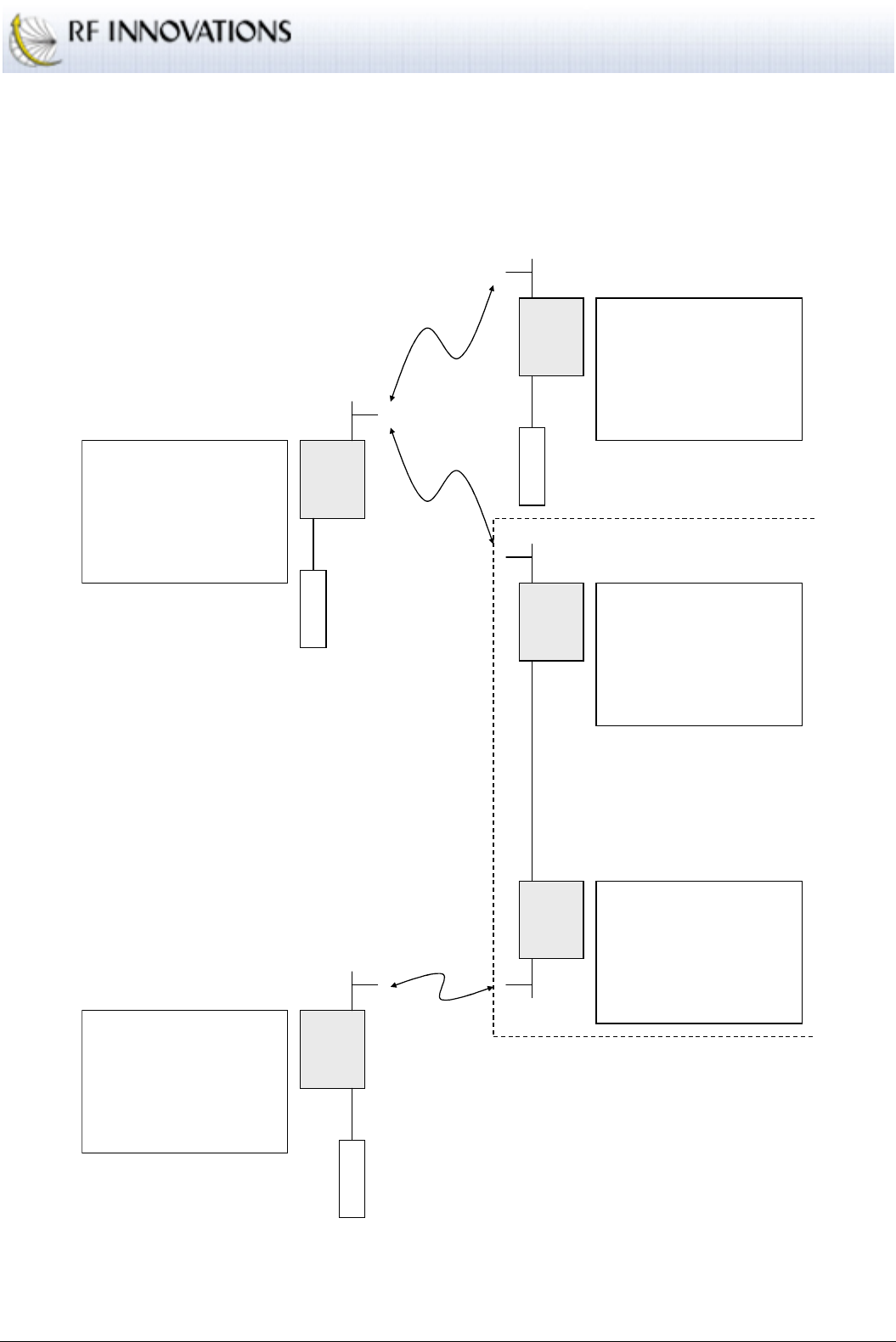
Applications
RFI-9256 Radio Modem User Manual Page 40 of 96
5.6 Broadcast Network with Back-to-back Repeaters
Back-to-back repeaters can be used in point-to-multipoint broadcast networks to extend the network range.
This scenario is shown in Figure 15.
RFI-9256
Master
RFI-9256
Repeater
Slave
Main
DTE
RADIO CONFIGURATION
Unit is a SLAVE
Network Address: 43
Hopping Pattern: 14
PROTOCOL CONFIGURATION
Main Port: Broadcast
SERIAL CONFIGURATION
Main Port: 115200, 8N1, Hardware Flow
RADIO CONFIGURATION
Unit is a MASTER
Network Address: 43
Hopping Pattern: 14
PROTOCOL CONFIGURATION
Main Port: Broadcast
SERIAL CONFIGURATION
Main Port: 115200, 8N1, Hardware Flow
RFI-9256
Repeater
Master
RFI-9256
Slave 2
Aux
DTE
RADIO CONFIGURATION
Unit is a SLAVE
Network Address: 43
Hopping Pattern: 15
PROTOCOL CONFIGURATION
Main Port: Broadcast
SERIAL CONFIGURATION
Main Port: 115200, 8N1, Hardware Flow
Main Null Modem Cable
Back-to-back Repeater
RADIO CONFIGURATION
Unit is a MASTER
Network Address: 43
Hopping Pattern: 15
PROTOCOL CONFIGURATION
Main Port: Broadcast
SERIAL CONFIGURATION
Main Port: 115200, 8N1, Hardware Flow
RFI-9256
Slave 1
RADIO CONFIGURATION
Unit is a SLAVE
Network Address: 43
Hopping Pattern: 14
PROTOCOL CONFIGURATION
Main Port: Broadcast
SERIAL CONFIGURATION
Main Port: 115200, 8N1, Hardware Flow
Main
DTE
Figure 15: Point-to-multipoint broadcast network with three destinations and a back-to-back repeater
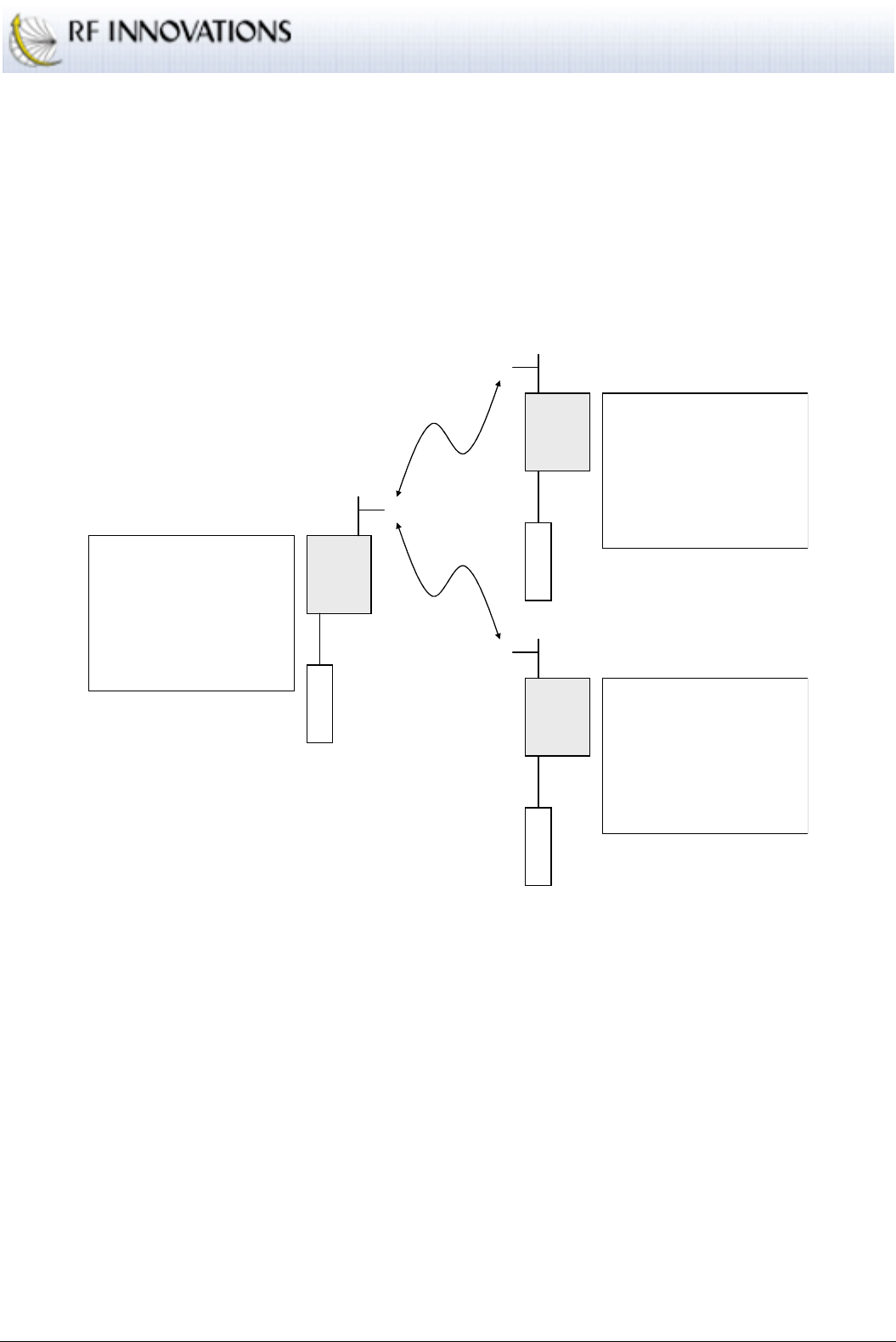
Applications
RFI-9256 Radio Modem User Manual Page 41 of 96
Each segment of the network consists of a master that is either connected to a DTE or to a slave that is on
another segment of the network. The transmissions from master 1 will be output on the main port of slave 1,
and thus be re-transmitted by master 2. In a similar fashion data received by master 2 will be output on its
main port and thus retransmitted by slave 1 back to master 1.
5.7 Hayes Dial-up Networking
The simplest form of Hayes dial-up networking is shown in Figure 16.
RFI-9256
Master
RFI-9256
Slave 1
Main
DTE
Main
DTE
RADIO CONFIGURATION
Unit is a MASTER
Network Address: 19
Hopping Pattern: 3
Local Address: 1000
PROTOCOL CONFIGURATION
Main Port: Hayes Dial-up
SERIAL CONFIGURATION
Main Port: 115200, 8N1, Hardware Flow
RFI-9256
Slave 2
Main
DTE
RADIO CONFIGURATION
Unit is a SLAVE
Network Address: 19
Hopping Pattern: 3
Local Address: 2000
PROTOCOL CONFIGURATION
Main Port: Hayes Dial-up
SERIAL CONFIGURATION
Main Port: 115200, 8N1, Hardware Flow
RADIO CONFIGURATION
Unit is a SLAVE
Network Address: 19
Hopping Pattern: 3
Local Address: 3000
PROTOCOL CONFIGURATION
Main Port: Hayes Dial-up
SERIAL CONFIGURATION
Main Port: 115200, 8N1, Hardware Flow
Figure 16: Hayes dial-up network
A single master unit can dial either slave 1 or slave 2. Either slave can dial the master unit.
Example dial strings from the master are:
ATD200001<CR>
: Dial the auxiliary port of slave 1 (address 2000, extension 01).
ATD300092<CR>
: Dials the internal menu system of slave 2 (address 3000, extension 92).
An example dial string from slave 1 is:
ATD 100000<CR>
: Dial the main port of the master (address 1000, extension 00).

Applications
RFI-9256 Radio Modem User Manual Page 42 of 96
5.8 Dial-up Networking with Back-to-back Repeaters
A Hayes dial-up network can be extended by one or more back-to-back repeaters. Figure 17 shows a Hayes
dial-up network where a single back-to-back repeater has been used to extend coverage.
RFI-9256
Master
RFI-9256
Repeater
Slave
Main
DTE
RADIO CONFIGURATION
Unit is a SLAVE
Network Address: 35
Hopping Pattern: 5
Local Address: 30
PROTOCOL CONFIGURATION
Main Port: Hayes Dial-up
Main Escape Char: ‘-‘
Main Escape Guard Time: 200ms
Main DTR: Hang-up on DTR Dropped
SERIAL CONFIGURATION
Main Port: 115200, 8N1, Hardware Flow
RADIO CONFIGURATION
Unit is a MASTER
Network Address: 35
Hopping Pattern: 5
Local Address: 1000
PROTOCOL CONFIGURATION
Main Port: Hayes Dial-up
SERIAL CONFIGURATION
Main Port: 115200, 8N1, Hardware Flow
RFI-9256
Repeater
Master
RFI-9256
Slave 3
RADIO CONFIGURATION
Unit is a SLAVE
Network Address: 35
Hopping Pattern: 6
Local Address: 5000
PROTOCOL CONFIGURATION
Main Port: Hayes Dial-up
SERIAL CONFIGURATION
Main Port: 115200, 8N1, Hardware Flow
Main Null Modem Cable
Back-to-back Repeater
RADIO CONFIGURATION
Unit is a MASTER
Network Address: 35
Hopping Pattern: 6
Local Address: 30
PROTOCOL CONFIGURATION
Main Port: Hayes Dial-up
Main Escape Char: ‘-‘
Main Escape Guard Time: 200ms
Main DTR: Hang-up on DTR Dropped
SERIAL CONFIGURATION
Main Port: 115200, 8N1, Hardware Flow
RFI-9256
Slave 1
RADIO CONFIGURATION
Unit is a SLAVE
Network Address: 35
Hopping Pattern: 5
Local Address: 2000
PROTOCOL CONFIGURATION
Main Port: Hayes Dial-up
SERIAL CONFIGURATION
Main Port: 115200, 8N1, Hardware Flow
Main
DTE
RFI-9256
Slave 2
RADIO CONFIGURATION
Unit is a SLAVE
Network Address: 35
Hopping Pattern: 6
Local Address: 4000
PROTOCOL CONFIGURATION
Main Port: Hayes Dial-up
SERIAL CONFIGURATION
Main Port: 115200, 8N1, Hardware Flow
Main
DTE
Main
DTE
Figure 17: Hayes dial-up network with three destinations and a back-to-back repeater

Applications
RFI-9256 Radio Modem User Manual Page 43 of 96
In order to establish a dial-up connection through a back-to-back repeater, an extension to the dialling
system is used. When dialling from the master unit in Figure 17, the following dial strings are used:
ATD30400000<CR>
: Establishes a dial-up connection between the master and slave with address
4000 main ports through the back-to-back repeater with address 30.
ATD30500091<CR>
: Establishes a dial-up connection between the master and the remote menu
system on the slave with address 5000 through the back-to-back repeater 30.
ATD200001<CR>
: Establish a connection with the auxiliary port of slave 1. As there is no back-to-
back repeater involved in the connection the format does not change.
ATD3091<CR>
: Establishes a dial-up connection from the master to the dial-up repeater slave
unit’s remote menu system.
ATD3000<CR>
: Establishes a dial-up connection from the master to the main port of the repeater
slave unit. This will in effect put the master radio in communications with the Hayes AT command
mode on the repeater master unit.
These last two dial strings illustrate how to access the terminal menu on either of the back-to-back repeater
units. In order to access the repeater slave’s terminal menu, dial up the menu system as if it were any other
slave. In order to access the repeater master’s terminal menu dial up the main port of the slave (the port that
has been connected through to the master unit), then use the master units AT command interface to bring up
the menu system via the
AT?
command.
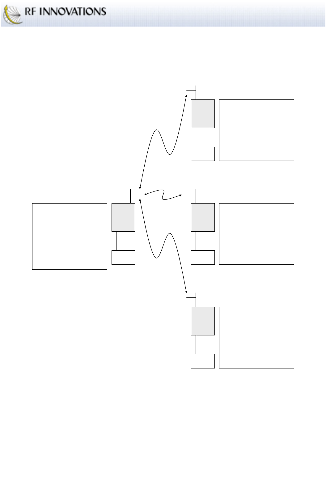
Applications
RFI-9256 Radio Modem User Manual Page 44 of 96
5.9 SCADA Network with Routing Table
A simple SCADA network using a routing table is shown in Figure 18.
RFI-9256
Master
RFI-9256
Slave 1
Main
Aux
RADIO CONFIGURATION
Unit is a MASTER
Network Address: 1
Hopping Pattern: 25
Local Address: 1000
PROTOCOL CONFIGURATION
Main Port: Modbus
Single Route: 71 -> 2000:01
Mapped Route: 55-56 -> 3001:00
SERIAL CONFIGURATION
Main Port: 9600, 8O1, No Flow
RFI-9256
Slave 2
Main
RADIO CONFIGURATION
Unit is a SLAVE
Network Address: 1
Hopping Pattern: 25
Local Address: 2000
PROTOCOL CONFIGURATION
Aux Port: Modbus
Default Route: 1000:00
SERIAL CONFIGURATION
Aux Port: 9600, 8O1, No Flow
RADIO CONFIGURATION
Unit is a SLAVE
Network Address: 1
Hopping Pattern: 25
Local Address: 3001
PROTOCOL CONFIGURATION
Main Port: Modbus
Default Route: 1000:00
SERIAL CONFIGURATION
Main Port: 9600, 8O1, No Flow
RFI-9256
Slave 2
Main
RADIO CONFIGURATION
Unit is a SLAVE
Network Address: 1
Hopping Pattern: 25
Local Address: 3002
PROTOCOL CONFIGURATION
Main Port: Modbus
Default Route: 1000:00
SERIAL CONFIGURATION
Main Port: 9600, 8O1, No Flow
RTU
MASTER
RTU 71
RTU 55
RTU 56
Figure 18: SCADA network with routing table
In all SCADA routing networks, data travels from the master to one of the slaves, or from one of the slaves
to the master. The slaves each require a default route with the master units address.
The routing table for the master is Table 12.
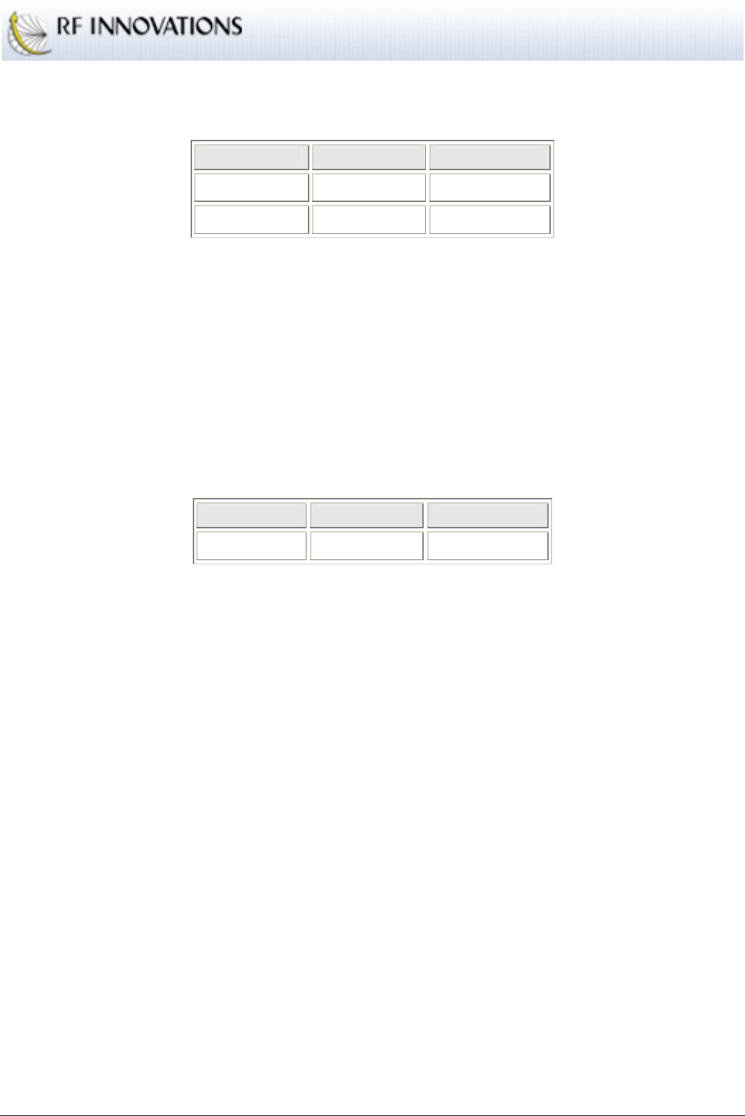
Applications
RFI-9256 Radio Modem User Manual Page 45 of 96
Route Type RTU Address Radio Address
Single Route 71 2000:01
Mapped Route 55-56 3001:00
Table 12: Master SCADA routing table
There are two routes used in this network. The first route is a single route that links RTU address 71 to radio
address 2000:01. All traffic with an RTU destination of 71 will be routed to the auxiliary port of the slave
with address 2000 (slave 1 in the above diagram).
The second route is a mapped route that links RTU addresses 55 and 56 to radio addresses 3001:00 to
3002:00. This means that traffic destined for an RTU with an address in the range 55-56 will be routed to the
main port of the slave with address 3001 + RTU Address – 55.
The slave units would all have the same routing table, shown in Table 13.
Route Type RTU Address Radio Address
Default Route N/A 1000:00
Table 13: Slave SCADA routing table
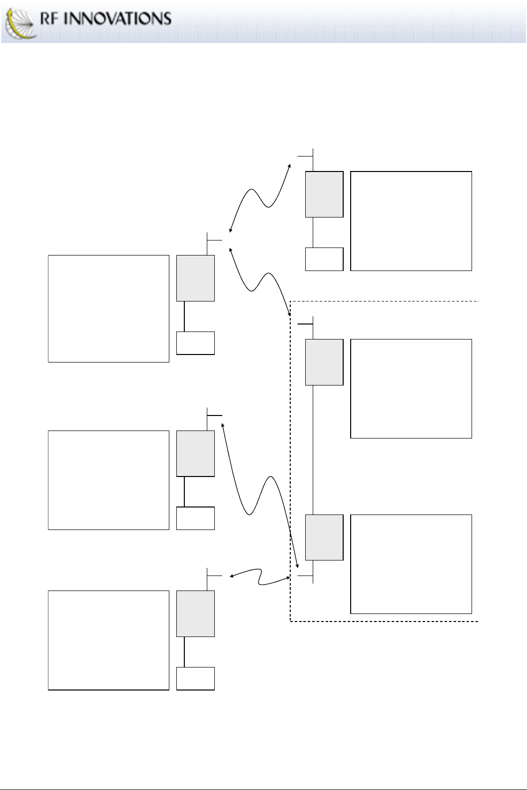
Applications
RFI-9256 Radio Modem User Manual Page 46 of 96
5.10 SCADA Network with a Back-to-back Repeater
SCADA networks can use back-to-back repeaters in order to extend the network coverage. This scenario is
shown in Figure 19.
RFI-9256
Master
RFI-9256
Repeater
Slave
Main
RADIO CONFIGURATION
Unit is a SLAVE
Network Address: 12
Hopping Pattern: 8
Local Address: 30
PROTOCOL CONFIGURATION
Main Port: Modbus
Default Route: 1000:00
SERIAL CONFIGURATION
Main Port: 9600, 8O1, No Flow
RADIO CONFIGURATION
Unit is a MASTER
Network Address: 12
Hopping Pattern: 8
Local Address: 1000
PROTOCOL CONFIGURATION
Main Port: Modbus
Single Route: 21 -> 2000:00
Range Route: 40-41 -> 30:00
SERIAL CONFIGURATION
Main Port: 9600, 8O1, No Flow
RFI-9256
Repeater
Master
RFI-9256
Slave 3
RADIO CONFIGURATION
Unit is a SLAVE
Network Address: 12
Hopping Pattern: 9
Local Address: 4008
PROTOCOL CONFIGURATION
Main Port: Modbus
Default Route: 30:00
SERIAL CONFIGURATION
Main Port: 9600, 8O1, No Flow
Main Null Modem Cable
Back-to-back Repeater
RADIO CONFIGURATION
Unit is a MASTER
Network Address: 12
Hopping Pattern: 9
Local Address: 30
PROTOCOL CONFIGURATION
Main Port: Modbus
Mapped Route: 40-41 -> 4007:00
SERIAL CONFIGURATION
Main Port: 9600, 8O1, No Flow
RFI-9256
Slave 1
RADIO CONFIGURATION
Unit is a SLAVE
Network Address: 12
Hopping Pattern: 8
Local Address: 2000
PROTOCOL CONFIGURATION
Main Port: Modbus
Default Route: 1000:00
SERIAL CONFIGURATION
Main Port: 9600, 8O1, No Flow
Main
RFI-9256
Slave 2
RADIO CONFIGURATION
Unit is a SLAVE
Network Address: 12
Hopping Pattern: 9
Local Address: 4007
PROTOCOL CONFIGURATION
Main Port: Modbus
Default Route: 30:00
SERIAL CONFIGURATION
Main Port: 9600, 8O1, No Flow
Main
Main
RTU
MASTER
RTU 21
RTU 40
RTU 41
Figure 19: SCADA network with a back-to-back repeater
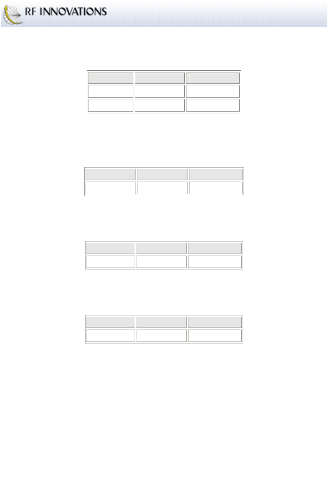
Applications
RFI-9256 Radio Modem User Manual Page 47 of 96
In this situation Master 1 must route all SCADA packets that are destined for the slaves connected to Master
2 to Slave 2, the slave component of the back-to-back repeater. This routing table is shown in Table 14
Route Type RTU Address Radio Address
Single Route 21 2000:00
Range Route 40-41 30:00
Table 14: Master 1 routing table
Master 2 must then correctly route all SCADA protocol packets onto the slaves in its network. This is done
using the routing table in Table 15
Route Type RTU Address Radio Address
Mapped Route 40-41 4007:00
Table 15: Master 2 routing table
The slaves that hang off master 1 must have the following routing table shown in Table 16.
Route Type RTU Address Radio Address
Default Route N/A 1000:00
Table 16: Slaves from master 1 routing table
The slaves that hang off master 2 must have the following routing table shown in Table 17.
Route Type RTU Address Radio Address
Default Route N/A 30:00
Table 17: Slaves from master 2 routing table

Applications
RFI-9256 Radio Modem User Manual Page 48 of 96
5.11 Point-to-point Auxiliary I/O
The simplest way to route auxiliary I/Os is in a point-to-point network as shown in Figure 20.
RFI-9256
Master RFI-9256
Slave
RADIO CONFIGURATION
Unit is a MASTER
Network Address: 61
Hopping Pattern: 13
Rx Address: 1000
PROTOCOL CONFIGURATION
Main Port: Point-to-point to 2000
AUXILIARY I/O CONFIGURATION
Auxiliary I/O Follows Remote ENABLED
Direction: Bit0 = output; Bit1 = input
0 1 … 7 0 1 … 7
RADIO CONFIGURATION
Unit is a MASTER
Network Address: 61
Hopping Pattern: 13
Rx Address: 1000
PROTOCOL CONFIGURATION
Main Port: Point-to-point to 2000
AUXILIARY I/O CONFIGURATION
Auxiliary I/O Follows Remote ENABLED
Direction: Bit0 = input; Bit1 = output
Figure 20: Point-to-point routing of auxiliary I/Os
In this scenario, the master has I/O 0 configured as an output, and I/O 1 configured as an input, while the
slave has I/O 0 configured as an input and I/O 1 configured as an output. I/O2 2 through 7 are not used.
The input applied to I/O 0 on the slave will be mirrored on the master, while the input applied to I/O 1 on the
master will be mirrored on the slave.
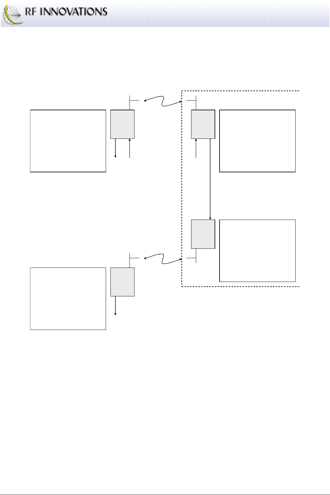
Applications
RFI-9256 Radio Modem User Manual Page 49 of 96
5.12 Point-to-point Auxiliary I/O with a Back-to-back Repeater
Auxiliary I/Os can also be routed through back-to-back repeaters by connecting the outputs on one radio to
the inputs on the second radio. Such a configuration is shown in Figure 21.
RFI-9256
Master RFI-9256
Repeater
Slave
RFI-9256
Repeater
Master
RFI-9256
Slave
1
Back-to-back Repeater
RADIO CONFIGURATION
Unit is a MASTER
Network Address: 52
Hopping Pattern: 22
Rx Address: 1000
PROTOCOL CONFIGURATION
Main Port: Point-to-point to 20
AUXILIARY I/O CONFIGURATION
Auxiliary I/O Follows Remote ENABLED
Direction: Bit0 = output; Bit1 = input
RADIO CONFIGURATION
Unit is a MASTER
Network Address: 52
Hopping Pattern: 22
Rx Address: 20
PROTOCOL CONFIGURATION
Main Port: Point-to-point to 1000
AUXILIARY I/O CONFIGURATION
Auxiliary I/O Follows Remote ENABLED
Direction: Bit0 = input; Bit1 = output
RADIO CONFIGURATION
Unit is a MASTER
Network Address: 52
Hopping Pattern: 23
Rx Address: 20
PROTOCOL CONFIGURATION
Main Port: Point-to-point to 3000
AUXILIARY I/O CONFIGURATION
Auxiliary I/O Follows Remote ENABLED
Direction: Bit1 = input
RADIO CONFIGURATION
Unit is a MASTER
Network Address: 52
Hopping Pattern: 23
Rx Address: 3000
PROTOCOL CONFIGURATION
Main Port: Point-to-point to 20
AUXILIARY I/O CONFIGURATION
Auxiliary I/O Follows Remote ENABLED
Direction: Bit1 = output
0 1 0
1
Figure 21: Point-to-point auxiliary I/O with a back-to-back repeater
In this scenario, I/O 0 has been configured as an output on master 1, and as an input on slave 1, thus output 0
on master 1 will mirror input 0 on slave 1.
Auxiliary I/O 1 on master 1 has been routed to I/O 1 on slave 2 via the back-to-back repeater. This is
achieved by configuring I/O 1 as an output on the repeater slave and as an input on the repeater master.
Thus, the value of I/O 1 will be mirrored on slave 1, which then feeds into master 2, and slave 2 will mirror
the value of I/O 1 on master 2.
Applications
RFI-9256 Radio Modem User Manual Page 50 of 96
5.13 Hayes Dial-up Auxiliary I/O
Hayes dial-up connections can be used to control auxiliary I/Os. Whenever a dial-up connection is
established, the I/Os will mirror each other. When the dial-up connection is terminated the I/O outputs on
either end of the connection will retain their state but will no longer change. This scenario is shown in Figure
22.
RFI-9256
Master
RFI-9256
Slave 1
RADIO CONFIGURATION
Unit is a MASTER
Network Address: 26
Hopping Pattern: 30
Local Address: 1000
PROTOCOL CONFIGURATION
Main Port: Hayes Dial-up
AUXILIARY I/O CONFIGURATION
Auxiliary I/O Follows Remote ENABLED
Direction: Bit0 = output; Bit1 = input
RFI-9256
Slave 2
RADIO CONFIGURATION
Unit is a SLAVE
Network Address: 26
Hopping Pattern: 30
Local Address: 2000
PROTOCOL CONFIGURATION
Main Port: Hayes Dial-up
AUXILIARY I/O CONFIGURATION
Auxiliary I/O Follows Remote ENABLED
Direction: Bit0 = input; Bit1 = output
RADIO CONFIGURATION
Unit is a SLAVE
Network Address: 26
Hopping Pattern: 30
Local Address: 3000
PROTOCOL CONFIGURATION
Main Port: Hayes Dial-up
AUXILIARY I/O CONFIGURATION
Auxiliary I/O Follows Remote ENABLED
Direction: Bit0 = input; Bit1 = output
0 1
0 1
0 1
Figure 22: Hayes Dial-up auxiliary I/O
In the Hayes dial-up situation, when the master dials slave 1, the auxiliary I/O 0 on the master will mirror the
value on the slave, while the input 1 on the master will be mirrored on output 1 on the slave. When the
master hangs-up the connection, output 1 on slave 1 will remain at the last value of input 1 on the master.
The same situation can be repeated when the master dials slave 2.
Appendix A Technical Specifications
RFI-9256 Radio Modem User Manual Page 51 of 96
Appendix A Technical Specifications
A.1 Type Approvals
Australia/ New Zealand AS/NZS 4771:2000 Australian Supplier ID: N161
FCC CFR 47 Part 15 Sub-Part C Section 15.247
FCC ID:
P5M9256TRX (radio modem)
P5M9256OEM (OEM module)
A.2 Radio Specifications
Range Up to 30km point-to-point
RS-232 Data Rates 110 baud – 115,200 baud
RS-232 Interface Asynchronous full duplex
Receiver Sensitivity -108 dBm @ 10
-4
raw BER
-100 dBm @ 10
-6
raw BER
Modulation Type Gaussian-Shaped FSK (GFSK)
Spreading Code Frequency-Hopping
Hopping Patterns 32 user selectable
Output Power 1mW – 1W (0dBm to +30 dBm)
Error Detection 32-bit CRC with packet re-transmit (ARQ)
Antenna BNC
Power Requirements 9.0 to 16.0 VDC
Power Consumption
350mA @ 12VDC Transmit
200mA @ 12VDC Receive
150mA @ 12VDC Average (normal data loading)
Connector DB-25 male (power and data combined)
Unit Address (Network ID) User programmable
Operating Modes
Point-to-point
Point-to-multipoint Broadcast
Hayes Dial-up
SCADA Protocol Router (ModBus, DNP3, TDE, Honeywell)
Back-to-back Repeater
Operating Environment -10ºC to +60ºC
Table 18: Radio Specifications

Appendix A Technical Specifications
RFI-9256 Radio Modem User Manual Page 52 of 96
A.3 Connector Pin Assignments
Pin Function
1 +12V input
2 Transmit data out (TXD) main port
3 Receive data in (RXD) main port
4 Transmit data out (TXD) auxiliary port
5 Receive data in (RXD) auxiliary port
6 I/O control 7
7 I/O control 5
8 I/O control 0
9 I/O control 2
10 Synchronisation I/O
11 NC
12 NC
13 GND
14 +12V input
15 CTS output (main port)
16 RTS input (main port)
17 DCD output (main port)
18 DTR input (main port)
19 I/O control 6
20 I/O control 4
21 I/O control 1
22 I/O control 3
23 NC
24 NC
25 GND
Table 19: RFI-9256 DB25 Pin Assignments
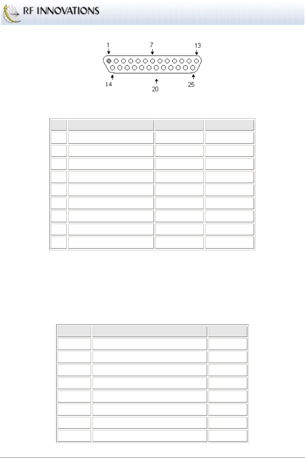
Appendix A Technical Specifications
RFI-9256 Radio Modem User Manual Page 53 of 96
Figure 23: DB25 pin numbering
Pin Function DTE Function DCE Function
1 Data Terminal Ready (DTR) Output Input
2 Received Data (RX) Input Output
3 Transmitted Data (TX) Output Input
4 Data Carrier Detect (DCD) Input Output
5 Signal Ground (SG)
6 Data Set Ready (DSR) Input Output
7 Clear to Send (CTS) Input Output
8 Ready to Send (RTS) Output Input
9 Ring Indicator (RI) Input Output
Table 20: DB9 Pin Assignments
A.4 Back-to-back Repeater Connector
The connector used for a back-to-back repeater is shown in Table 21. Note that the main and auxiliary port
have been crossed to form a null modem cable (highlighted sections). All eight auxiliary I/O lines along with
synchronisation I/O are passed straight through.
Slave Pin Function Master Pin
1 +12V input
2 Transmit data out (TXD) main port 3
3 Receive data in (RXD) main port 2
4 Transmit data out (TXD) auxiliary port 5
5 Receive data in (RXD) auxiliary port 4
6 I/O control 7 6
7 I/O control 5 7
8 I/O control 0 8
Appendix A Technical Specifications
RFI-9256 Radio Modem User Manual Page 54 of 96
9 I/O control 2 9
10 Synchronisation I/O 10
11 NC
12 NC
13 GND 13
14 +12V input
15 CTS output (main port) 16
16 RTS input (main port) 15
17 DCD output (main port) 18
18 DTR input (main port) 17
19 I/O control 6 19
20 I/O control 4 20
21 I/O control 1 21
22 I/O control 3 22
23 NC
24 NC
25 GND
Table 21: RFI-9256 back-to-back repeater pin assignments
A.5 Power Supply Notes
Power supplies used to power the RFI-9256 should have sufficient current rating and ripple rejection.
Typically <500m VRMS of power supply noise can be tolerated. The RFI-9256 contains a built in thermal
fuse that will open the circuit in the event of any over current conditions, over temperature or reverse
polarity. Power supplies used should be capable of at least 1A continuous current.
A.6 Version Numbering Scheme
The RFI-9256 contains a firmware version string. This version string provides some information regarding
compatibility with other firmware versions, and consists of:
Product Name
: Identifies the radio hardware type.
Major and Minor Number
: The major number generally reflects the hardware compatibility of
the firmware but may be incremented if the firmware has had a major overhaul. The minor number
is incremented as new suites of functionality have been added or when changes have been made
which render the firmware incompatible with previous versions. Combined they are the version
number.
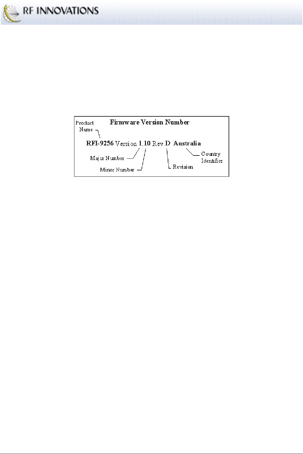
Appendix A Technical Specifications
RFI-9256 Radio Modem User Manual Page 55 of 96
Revision
: The revisions reflect bug fixes or minor changes that don’t render the system
incompatible.
Country
: Firmware with versions with different country identifiers, are always incompatible with
their air interface. This is due to the frequencies and hopping sequences that they use. Each
country has its own spectrum allocation and laws governing radio spectrum usage.
An example version number string is shown in Figure 24.
Figure 24: Example firmware version number
Firmware revisions with major version number 1 will be compatible with this hardware build, while
firmware revisions with major version number 1 and minor version number 10 will be compatible over the
air with this build.
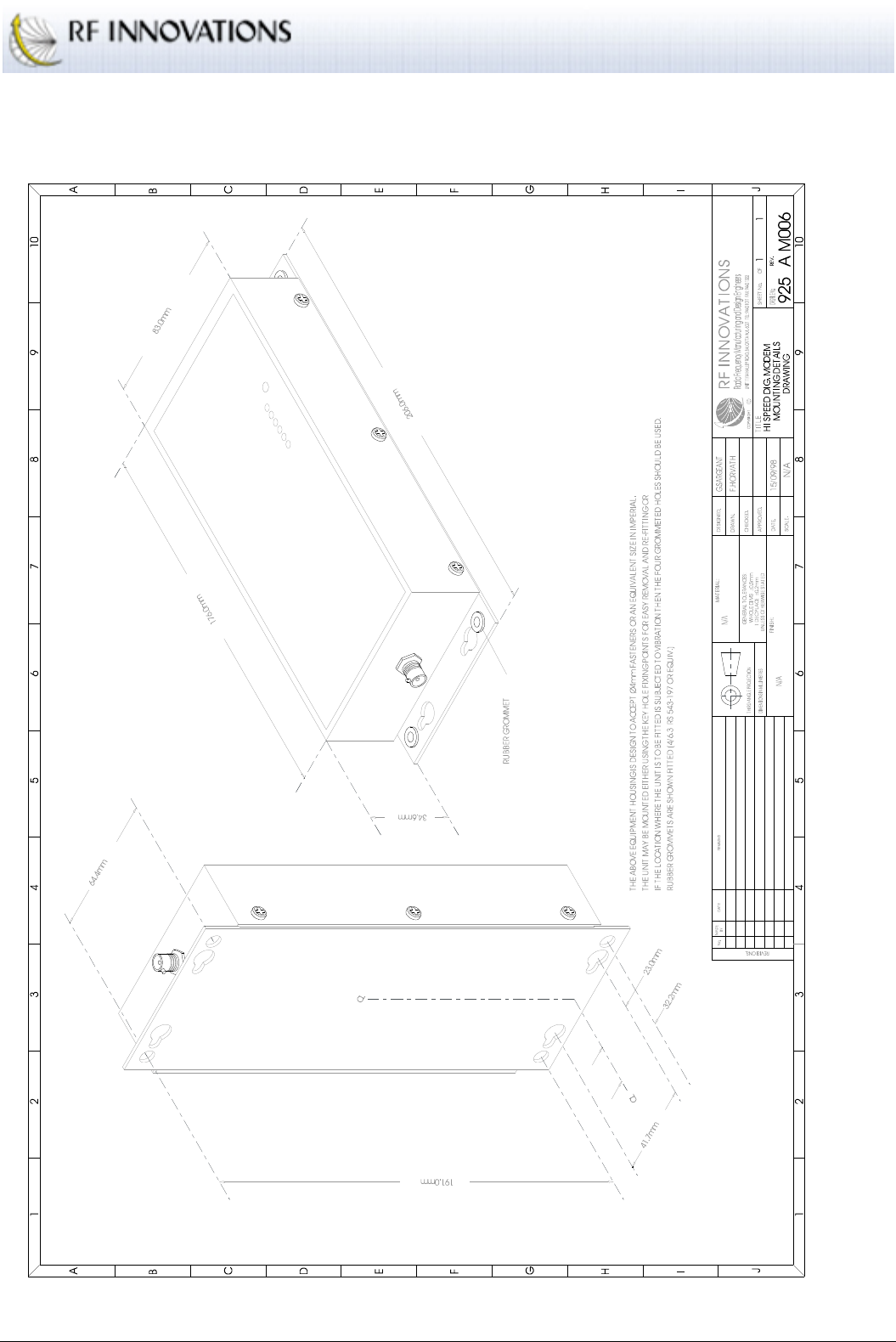
Appendix A Technical Specifications
RFI-9256 Radio Modem User Manual Page 56 of 96
A.7 Case Dimensions
Figure 25: Case physical dimensions

Appendix B Terminal Menu Reference
RFI-9256 Radio Modem User Manual Page 57 of 96
Appendix B Terminal Menu Reference
*** MiROS MAIN MENU (Version 2.0) ***
RFI-9256 Version 1.30 Rev.D
Unit Name: test
Unit is a: SLAVE
Serial No: 207311DF2765
Manufactured Date: 30/01/2002
(R) Radio Configuration Menu
(L) Protocol Port Selection
(S) Serial Port Configuration Menu
(M) Radio and I/O Configuration Menu
(P) Radio Personality Menu
(D) Diagnostics Menu
(Esc) To Exit Menu
Enter Choice:
Figure 26: Main menu
Status Information:
The main menu displays the RFI-9256 model and firmware revision (1.30
Rev D in Figure 26), along with the unit name, current mode, serial number and manufacture date.

Appendix B Terminal Menu Reference
RFI-9256 Radio Modem User Manual Page 58 of 96
B.1 (R) Radio Configuration Menu
*** Radio Configuration Menu ***
Unit is a: SLAVE
Network Address = 32
Rx Address = 20
Hopping Pattern = 0
Point to Multipoint Dialup Connection
(M) Set unit as Master
(S) Set unit as Slave
(N) Set Network address
(L) Set Local Rx address
(P) Set ports as Point to Point Direct
(D) Set ports as Point to Multipoint Dialup
(R) Set ports as Dialup Repeater
(1) Special Controls Menu
(2) Link Control Menu
(3) Radio Characteristics Menu
(F) Restore Factory defaults
(Esc) Previous Menu
Enter Choice:
Figure 27: Radio configuration menu
Set unit as Master:
In any communications link, at least one radio must be configured as a
master. The master synchronises communications with the slaves, and a may communicate with
any slave. A master may not communicate with another master unit.
Set unit as Slave:
In any communication link one unit must be set as a master and the rest as
slaves. Slaves can initiate communication but follow the synchronisation of the master. A slave
can only communicate with the master.
Set Network address:
The network address is the network identification number, and every radio
on a single network must have the same network address. Slaves will only synchronise with a
master that has the same network address. Radios ignore data originating from a radio with another
network address. A maximum of 64 network addresses are available, in the range 0 to 63.
Set Local Rx Address
: The local address is used to identify individual radios within a network.
Each radio must have a unique address, otherwise destructive collisions will occur. It is advised
that individual radios be given an address in the range 1000-9999, while radios configured as
repeaters (see section Back-to-back Repeater Operation on page 23) must be given the same local
address in the range 10-99.
Radios in different networks can have the same local address.

Appendix B Terminal Menu Reference
RFI-9256 Radio Modem User Manual Page 59 of 96
Set ports as Point to Point Direct
: This is a shorthand way of configuring a point-to-point
connection on both main and auxiliary ports. For more information see section 4.3.1.
Set ports as Point to Multipoint Dialup
: This is a shorthand way of configuring a point-to-
multipoint dial-up connection on both main and auxiliary ports. For more information see section
4.3.3.
Set ports as Dialup Repeater
: A repeater extends the range of a RFI-9256 radio network.
Repeaters consist of a pair of radios, one master and one slave wired together in a back-to-back
configuration. This is covered in the section Back-to-back Repeater Operation on page 23. This
function will configure the current RFI-9256 for dial-up repeater operation, with the settings for
Hayes dialup described in the section Dial-up Networking with Back-to-back Repeaters on page
27.
Special Controls Menu
: When the antennas from more than one radio are placed within close
proximity, the units may be synchronised to prevent interference. One radio must be configured to
output a synchronisation signal while the other radio follow the synchronisation signal. Slave units
cannot be configured to follow an external synchronisation signal as the slave must synchronise
from the master of its network. In order for synchronisation to operate correctly both radios must
be configured with the same frame length and bias setting. For more information see the section
Synchronisation on page 22. The following synchronisation options are available:
(a) Follow Sync Signal
: The radio will follow a synchronisation signal provided by another.
Only the master radio can have this option configured.
(b) Output Sync Signal
: The radio will output the frame synchronisation signal.
(c) Repeater Sync Mode
: The radio will follow a synchronisation signal provided by another. In
this case the radio will synchronise to a 50% offset.
(d) No Sync Mode
: Disables synchronisation.
Restore Factory defaults
: Restores the default settings of the RFI-9256. The factory defaults
settings are given in Appendix D.

Appendix B Terminal Menu Reference
RFI-9256 Radio Modem User Manual Page 60 of 96
B.1.1 (2) Link Control Menu
*** Link Control Menu ***
Main Port: ARQ Retries = 50
Aux Port: ARQ Retries = 50
Network Fail Timer = 5000ms
Online Request Timer = 1000ms
Backoff Retry is Disabled
(A) Number of Retries for ARQ
(F) Network Fail Timer
(O) Online Request Timer
(B) Backoff Retries Enable/Disable
(Esc) Previous Menu
Enter Choice:
Figure 28: Link control menu
Number of Retries for ARQ
: The ARQ (automatic repeat request) controls the number of times
the radio will resend a packet of lost information before discarding the packet. This can be set as
high as 255 retries. Each serial port can be configured independently allowing for modes like
broadcast (where a low retry count is desirable) to co-exist with point-to-point or Hayes dial-up
modes on the same radio. This is done through the protocol link control menu outlined in
Appendix B.2.2.3.
Network Fail Timer
: The network fail timeout controls the time a slave waits when a signal is
lost before attempting to re-synchronise. The network link LED on the front panel also indicates
this loss.
Online Request Timer
: This timer controls the length of time between integrity checks between
radios running in point-to-point or Hayes dial-up modes.
Backoff Retries Enable / Disable
: When several slaves are to be connected simultaneously to a
single master, they should be configured with back-off retries. This allow for collisions between
the slaves to be resolved using exponential back off and retry.

Appendix B Terminal Menu Reference
RFI-9256 Radio Modem User Manual Page 61 of 96
B.1.2 (3) Radio Characteristics Menu
*** Radio Characteristics Menu ***
Hopping Pattern = 0
Tx Power Level = 20 dBm
RSSI trigger level = -110
Frame Time = 20 milliseconds
Max Tx bytes per frame = 113
Directional Bias is Disabled
(H) Hopping Pattern
(P) Tx Power Menu
(R) RSSI trigger level
(F) Frame Time Menu
(B) Directional Bias Menu
(Esc) Previous Menu
Enter Choice:
Figure 29: Radio characteristics menu
Hopping Pattern:
There are 32 (0-31) hopping patterns available. The hopping pattern determines
how the radio hops through the frequency spectrum. Co-located master units should all use
different hopping patterns to minimise interference, and all units on the same network must have
the same hopping pattern.
It is advised that the default hopping pattern not be used in order to minimise the change of
interference with other RFI-9256 in the area.
Tx Power Menu:
The transmit power menu allows the user to select the output power of the RFI-
9256. The options are:
(a)
OFF
(b)
0 dBm
(c)
+10 dBm
(d)
+20 dBm
(e)
+25 dBm
(f)
+30 dBm
The total output power from the antenna must not exceed 1W EIRP (30dBm) noting that antennas
will usually provide gain, and cables and connectors produce a loss.
RSSI trigger level:
The RFI-9256 will only attempt to acquire data if the power on the channel
exceeds the RSSI trigger level. This can be configured between -120dBm and -50dBm, however

Appendix B Terminal Menu Reference
RFI-9256 Radio Modem User Manual Page 62 of 96
setting this to greater than the radio sensitivity (-108dBm) will cause an artificial loss in sensitivity
and should only be done in noisy environments.
Frame Time Menu:
This function changes the maximum length (in time) of each packet frame.
The size in bytes of each frame, and the available frame times is covered in the section RSSI Trip
Level on page 20.
Directional Bias Menu:
The directional bias menu allows the master/slave biasing of frames to be
adjusted. This is often used in simplex systems. The effect of biasing frames is covered in the
section Directional Bias on page 21.
B.2 (L) Protocol Port Selection Menu
*** Protocol Port Selection ***
Main Port: Protocol Type: Hayes Dialup
Aux Port: Protocol Type: Hayes Dialup
(M) Main Port
(A) Aux Port
(Esc) Previous Menu
Enter Choice:
Figure 30: Protocol Port Selection Menu
Main Port:
Select to change the protocol on the Main Port and bring up the menu shown in Figure
31
Aux Port:
Select to change the protocol on the Auxiliary Port.
*** Link/Port Protocol Menu ***
Main Port: Protocol Type: Hayes Dialup
(P) Protocol Selection Menu
(C) Configure Protocol Menu
(Esc) Previous Menu
Enter Choice:
Figure 31: Link/Port protocol menu for the main port

Appendix B Terminal Menu Reference
RFI-9256 Radio Modem User Manual Page 63 of 96
B.2.1 (P) Protocol Selection Menu
*** Protocol Selection Menu ***
Main Port: Protocol Type: Hayes Dialup
(P) Point to Point
(B) Broadcast
(D) Hayes Dialup
(M) Modbus
(H) Honeywell
(3) DNP3
(T) TDE
(X) Disabled
(Esc) Previous Menu
Enter Choice:
Figure 32: Protocol selection menu
Point to Point:
Configures the serial port for point-to-point operation. See section 4.3.1 for more
information on point-to-point network operation.
Broadcast:
Configures the serial port for point-to-multipoint broadcast operation. See section
4.3.2 for more information on point-to-multipoint broadcast network operation.
Hayes Dialup:
Configures the serial port for Hayes dial-up operation. See section 4.3.3 for more
information on Hayes dial-up network operation.
Modbus:
Configures the serial port for the Modbus SCADA protocol. See section 4.3.4 for more
information on SCADA protocol network operation.
Honeywell:
Configures the serial port for the Honeywell SCADA protocol.
DNP3:
Configures the serial port for the DNP3 SCADA protocol using the FT3 frame formal
(LPDU).
TDE:
Configures the serial port for the Introl systems TDE protocol.
Disabled:
Disables any transmission of data though the selected serial port.

Appendix B Terminal Menu Reference
RFI-9256 Radio Modem User Manual Page 64 of 96
B.2.2 (C) Configure Protocol Menu
*** Configure Protocol Menu ***
Main Port: Protocol Type: Hayes Dialup
(M) Hayes Command Control Menu
(R) Route Manager Menu
(L) Link Control Menu
(Esc) Previous Menu
Enter Choice:
Figure 33: Configure protocol menu
B.2.2.1 (M) Hayes Command Control Menu
*** Hayes Command Control Menu ***
Main Port: Hang-up on DTR Dropped, Echo is ON, Response is ON, Auto-
answer is
ON
Escape character = + Escape guard time = 1000ms
Connect Timeout = 9985ms
Ring Count = 1
(C) Connect Timeout
(X) Escape character (ie +)
(G) Escape guard time
(H) Hang-up on DTR (low)
(Z) Hang-up on DTR Dropped
(L) Local on DTR (low)
(I) Ignore DTR
(E) Echo (ON/OFF)
(R) Response codes (ON/OFF)
(A) Auto-answer (ON/OFF)
(N) Set Max Rings
(D) Set to Defaults
(Esc) Previous Menu
Enter Choice:
Figure 34: Hayes command control menu
Connect Timeout:
The maximum amount of time that the radio will wait for a connection
response, configurable between 100 and 30000ms.

Appendix B Terminal Menu Reference
RFI-9256 Radio Modem User Manual Page 65 of 96
Escape character (i.e., +):
Sets the escape character. This is the character that is used in the
escape sequence to return from online state to local command state. The escape sequence consists
of the escape character being typed three times, with set communication-free periods of time
before and after the sequence. Back-to-back repeaters used in Hayes dial-up mode should have the
escape character set to ‘-‘. See the section Back-to-back Repeater Operation on page 23.
Escape guard time:
The time before and after the escape sequence has been entered that there
needs to be no activity for the radio to enter local command state.
Hang-up on DTR (low):
DTR is an RS-232 signal used to indicate to the radio whether the local
terminal is ready to communicate. Hang-up on DTR (low) causes a connection to be broken
whenever the DTR line is low.
Hang-up on DTR Dropped:
Hang-up on DTR dropped is used to disconnect whenever DTR
changes from a high to a low.
Local on DTR (low):
When DTR is low the radio goes into local command state. This is
equivalent to typing the escape sequence. Once the unit is in local command state, it will only
return to online state if the
ATO
command is issued. DTR should be high at this time to prevent the
radio immediately returning to local command state.
Ignore DTR:
The radio does not use the DTR signal to control its connection state.
Echo (ON/OFF):
Toggles the echo setting between on and off. When on characters typed at the
terminal will be echoed back to the screen while in local command state.
Response codes (ON/OFF):
This toggles whether the radio returns response codes. If the
response codes are on, all codes such as
OK
,
CONNECT
, and
NO CARRIER
will be returned to the
terminal.
Auto-answer (ON/OFF):
When auto-answer is on, the radio will automatically answer any
incoming call after the maximum number of rings has passed. When auto-answer is off the
ATA
command must be used to answer an incoming call.
Set Max Rings:
Sets the number of
RING
messages to output before automatically answering.
Set to Defaults:
Restores the Hayes settings to their factory defaults for the selected port. The
factory defaults are given in Appendix D.

Appendix B Terminal Menu Reference
RFI-9256 Radio Modem User Manual Page 66 of 96
B.2.2.2 (R) Route Manager Menu
*** Route Manager Menu ***
Main Port: Protocol Type: Modbus
Used Space : 0
Free Space : 3935
Total Routes : 0
Single Routes : 0
Mapped Routes : 0
Range Routes : 0
No Default Route
(A) Add Route
(D) Delete Route
(X) Delete All Routes
(L) List All Routes
(T) List Routes by Type
(Esc) Previous Menu
Enter Choice:
Figure 35: Route manager menu
Add Route:
Adds a new route to the routing table.
Delete Route:
Deletes an existing route from the routing table.
Delete All Routes:
Deletes all routes in the routing table for the selected port.
List All Routes:
Lists all the configured routes for this RFI-9256. Slave radios only have a default
route configured, while masters may have an extensive routing table. The following items are
displayed for each route:
(a) IDX
is the individual route identifier.
(b) Route Type
is the type of route (single, mapped or range).
(c) Route Source
is the destination address that is found in the protocol packet.
(d) Destination Radio
is the radio that the packet is sent to.
List Routes by Type:
Provides a list of all routes sorted by the route type.

Appendix B Terminal Menu Reference
RFI-9256 Radio Modem User Manual Page 67 of 96
B.2.2.3 (L) Link Control Menu
*** Link Control Menu ***
Main Port: ARQ Retries = 50
Network Fail Timer = 5000ms
Online Request Timer = 1000ms
(A) Number of Retries for ARQ
(F) Network Fail Timer
(O) Online Request Timer
(Esc) Previous Menu
Enter Choice:
Figure 36: Link control menu
Number of Retries for ARQ:
Sets the number of ARQ retries to be used on the selected port. See
section B.1.1 for more information.
Network Fail Timer:
Sets the network fail timer for the selected port. See section B.1.1 for more
information.
Online Request Timer:
Sets the online request timer for the selected port. See section B.1.1 for
more information.
B.3 (S) Serial Port Configuration Menu
*** Port Selection Menu ***
Main Port: 19200 Baud, No Parity, 8 Data, 1 Stop, No Flow
Main Port: Packet Timers: Output = Disabled, Input = Disabled
Aux Port: 19200 Baud, No Parity, 8 Data, 1 Stop, No Flow
Aux Port: Packet Timers: Output = Disabled, Input = Disabled
(M) Main Port
(A) Aux Port
(Esc) Previous Menu
Enter Choice:
Figure 37: Serial port selection menu
Main Port:
Allows the serial port settings for the main port to be configured as shown in Figure
38.

Appendix B Terminal Menu Reference
RFI-9256 Radio Modem User Manual Page 68 of 96
Aux Port:
Allows the serial port settings for the auxiliary port to be configured.
*** Serial Port Configuration Menu ***
Main Port: 19200 Baud, No Parity, 8 Data, 1 Stop, No Flow
Main Port: Packet Timers: Output = Disabled, Input = Disabled
Main Port: Rx Buffer Limit = 3072
(B) Baud Rate Menu
(F) Flow Control Menu
(N) No Parity
(E) Even Parity
(O) Odd Parity
(1) One Stop Bit
(2) Two Stop Bits
(7) Seven Bit Data
(8) Eight Bit Data
(A) Advanced Functions Menu
(D) Set to Defaults
(Esc) Previous Menu
Enter Choice:
Figure 38: Main serial port configuration menu
Baud Rate Menu:
Selects the serial port baud rate for this port.
Flow Control Menu:
Selects the flow control method used for this port. The main port supports
both hardware and software flow control, while the auxiliary port only supports software flow
control
No Parity / Even Parity / Odd Parity:
Selects the parity to use on the serial port.
One Stop Bit / Two Stop Bits:
Selects the number of stop bits to use on the serial port.
Seven Bit Data / Eight Bit Data:
Selects the number of data bits to use on the serial port.
Set to Defaults:
Restores the factory default settings for the serial port. The factory defaults are
given in Appendix D.

Appendix B Terminal Menu Reference
RFI-9256 Radio Modem User Manual Page 69 of 96
B.3.1 (A) Advanced Functions Menu
*** Advanced Functions Menu ***
Main Port: Packet Timers: Output = Disabled, Input = Disabled
Main Port: Rx Buffer Limit = 3072
(T) Tx (Out) Packetiser Timer
(R) Rx (In) Packetiser Timer
(L) Rx Buffer Limit
(Esc) Previous Menu
Enter Choice:
Figure 39: Advanced functions menu
Tx (Out) Packetiser Timer:
The tx (out) packetiser timer is used to packetise data incoming from
the RF. When the packetising time has passed with no further data being received, all data will be
output on the serial port.
Rx (In) Packetiser Timer:
The rx (in) packetiser timer is used to packetise data that comes into
the serial port. When the packetising time has passed with no data received on the serial port, all
available data is transmitted over the air.
Rx Buffer Limit:
The rx buffer limit allows control over how full the internal buffer should get
before flow control is triggered.
B.4 (M) Radio and I/O Configuration Menu
*** Radio and I/O Configuration Menu ***
(H) Hayes Command Control Menu
(D) DCD Output Control Menu
(R) CTS Output Control Menu
(A) Auxiliary I/O Config Menu
(Esc) Previous Menu
Enter Choice:
Figure 40: Radio and I/O configuration menu
DCD Output Control Menu:
DCD (Data Carrier Detect) is an output from the RFI-9256 that can
be set to one of the options given in section 4.1.2.
CTS Output Control Menu:
The CTS (clear to send) output is used in flow control. When it is
not being used for hardware flow control it can be set to one of the options given in section 4.1.2.

Appendix B Terminal Menu Reference
RFI-9256 Radio Modem User Manual Page 70 of 96
B.4.1 (H) Hayes Command Control Menu
*** Port Selection Menu ***
Main Port: Hang-up on DTR Dropped, Echo is ON, Response is ON, Auto-
answer is
ON
Escape character = + Escape guard time = 1000ms
Connect Timeout = 9985ms
Ring Count = 1
Aux Port: Echo is ON, Response is ON, Auto-answer is ON
Escape character = + Escape guard time = 1000ms
Connect Timeout = 9985ms
Ring Count = 1
(M) Main Port
(A) Aux Port
(Esc) Previous Menu
Enter Choice:
Figure 41: Hayes command control menu
Main Port:
Select to change the Hayes Command settings on the Main Port. This is the same
menu as described in B.2.2.1.
Aux Port:
Select to change the Hayes Command settings on the Auxiliary Port. This is the same
menu as described in B.2.2.1.
B.4.2 (A) Auxiliary I/O Port
*** Auxiliary I/O Config Menu ***
Sample Time = 500 (ms)
Aux I/O Follows remote = Disabled
(D) Aux I/O Direction Menu
(P) Powerup defaults Menu
(S) Sample Rate
(F) Aux I/O Follows remote
(E) Enable/Disable Aux I/O
(Esc) Previous Menu
Enter Choice:
Figure 42: Auxiliary I/O menu

Appendix B Terminal Menu Reference
RFI-9256 Radio Modem User Manual Page 71 of 96
Aux I/O Direction Menu:
Allows individual configuration of each I/O line as either an input or
an output.
Powerup defaults Menu:
Sets the default state of each output line when power is applied to the
RFI-9256.
Sample Rate:
The number of milliseconds between each sample of the digital inputs. The smaller
the sample time the faster changes will be propagated across the radio network. The sampling time
can be set between 8ms and 5000ms.
Aux I/O Follows remote:
Toggles auxiliary I/O control via a remote radio.
Enable/Disable Aux I/O:
Enables or disables the auxiliary I/O port.
B.5 (P) Radio Personality Menu
*** Radio Personality Menu ***
Unit Name:
Time: 00:18:27
Menu Password is Disabled
Security Code is Disabled
Menu Timeout is 15 minutes
(U) Set Unit Name
(P) Set Menu Password
(R) Remove Menu Password
(S) Set Security Code
(D) Delete Security Code
(T) Set Current Time
(M) Set Menu Timeout
(Esc) Previous Menu
Enter Choice:
Figure 43: Radio personality menu
Set Unit Name:
Sets the name of the unit. This can help identify each unit on the network by
name, location, number or function.
Set Menu Password:
Sets the menu password to prevent an unauthorised person from entering the
menu system and changing the radio’s settings.
Remove Menu Password:
Removes the password used to access the radio's menu, disabling
password protection.

Appendix B Terminal Menu Reference
RFI-9256 Radio Modem User Manual Page 72 of 96
Set Security Code:
Sets the security code. The security code protects the radio network from
interference from other networks using RFI-9256 radio radios. The code is a 32-bit (9 digit)
number, which allows 0 to 4294967295 combinations.
Delete Security Code:
Clears the security code
Set Current Time:
Sets the internal real-time clock. The real-time clock on the RFI-9256 does not
use non-volatile storage, and thus will be reset whenever power is removed.
Set Menu Timeout :
Sets the amount time a menu remains idle before it is closed.
B.6 (D) Diagnostics Menu
*** Diagnostics Menu ***
(S) Display Status
(E) Event Log Menu
(T) Test Indicator LEDs
(D) Test Digital Outputs
(N) Show channel signal/noise
(L) Show Stats/Logging
(M) Test Link Margin
(1) Statistics Menu
(2) Display Tasks
(3) Display Links
(Esc) Previous Menu
Enter Choice:
Figure 44: Diagnostics menu
Display Status:
This function gives a summary of the information regarding the configuration of
the radio.
Test Indicator LEDs:
Selecting this function starts a test of the front panel LEDs. This is a visual
test and the LEDs must be observed while this test is in progress. It simply turns the LEDs on and
off operating using all the colours in a predefined sequence.
Test Digital Outputs:
This will cause all the auxiliary I/Os to be set as outputs, and then each I/O
turned on then off in turn. This is used to test the functionality of the I/O port.
Show channel signal/noise:
When this function is selected, a table showing the signal and noise
levels for each channel is displayed. If a ‘??’ is displayed as the signal value then there wasn’t a
recent sample for that channel.
Show Stats/Logging:
Shows the statistics relating to the quality of the data throughput and
information regarding the performance of both serial ports.

Appendix B Terminal Menu Reference
RFI-9256 Radio Modem User Manual Page 73 of 96
Test Link Margin:
Displays the average signal and average noise the radio is measuring. If the
unit is configured as a master then it will require an address of the slave.
Display Links:
Displays all the links that the radio current has established. This is a table with the
following items:
(a) Idx
: the index number used internally.
(b) LocSrc
: the local port number that is the source/destination for the data.
(c) LocExt
: the extension that has been dialled if a remote has dialled this unit
(d) DestSrc
: the remote port that is the source/destination for the data
(e) DestExt
: the extension that this unit has dialled.
(f) DestAddr
: the remote unit address.
(g) State
: the internal state of the link.
(h) Link Name
: is the name assigned to the link. It reflects the mode of operation for that link.
The source/destination ports are one of three ports, the main, auxiliary or the virtual port. The virtual
port is an internal port used by the radio to communicate through the menus.
B.6.1 (E) Event Log Menu
*** Event Log Menu ***
Log Level = General Information
(V) View Log
(L) Logging Level Menu
(C) Clear Log
(Esc) Previous Menu
Enter Choice:
Figure 45: Event log menu
View Log:
Used to view the debugging information supplied by the radio.
Logging Level Menu:
Selected to change the type of information logged by the radio for display
when viewing the log. There are five available levels.
(a) Errors
: Only displays severe errors.
(b) Warnings
: Displays both errors and warnings.
(c) State
: Displays state changes, along with errors and warnings.
(d) Info
: Displays all available information, along with stats, errors, and warnings.
(e) Debug
: Displays internal debugging information along with info, states, warnings, and errors.
Clear Log:
Clears the log.

Appendix B Terminal Menu Reference
RFI-9256 Radio Modem User Manual Page 74 of 96
B.6.2 (1) Statistics Menu
*** Statistics Menu ***
(N) Show channel signal/noise
(L) Show Stats/Logging
(P) Reset Physical Layer Logging
(S) Reset Serial Logging
(Esc) Previous Menu
Enter Choice:
Figure 46: Event log menu
Show channel signal / noise:
This function is exactly the same as in the diagnostics menu in
section B.6.
Show Stats/Logging:
This function is exactly the same as in the diagnostics menu in section B.6.
Reset Physical Layer Logging:
Clears the RF logging information.
Reset Serial Logging:
Clears the serial port logging information.
Appendix C Hayes AT Command Reference
RFI-9256 Radio Modem User Manual Page 75 of 96
Appendix C Hayes AT Command Reference
C.1 Radio Commands
C.1.1 “AT?” Menu Mode
This command enables the menu system on the current Hayes port. When the menu is exited the radio will
return to AT command mode.
C.1.2 “ATD” Dial
This command dials a remote unit. The basic dialling command is:
ATD<address><extension>
Where
<address>
is the address of the remote unit, and
<extension>
is the extension number to dial. For
a list of extension numbers see section 4.3.3.
Hyphens, spaces, and colons can be used to make the command more readable, however these will be
ignored by the radio. For example, the command
ATD30200001
is equivalent to
ATD 30-2000:01
.
Dial commands cannot be concatenated with other AT commands. More information can be found in the
section Connection Management on page 27.
C.1.3 “ATE” Echo
The echo command enables or disables the echoing of input characters in local command state.
Command Description
ATE0
Disable local command echo.
ATE1
Enable local command echo.
Table 22: ATE Echo commands
C.1.4 “ATH” Hang Up
The hang-up command forces the radio to terminate the current dial-up connection.
C.1.5 “ATI” Information
The information commands can be used to return various information about the radio. The list of commands
are shown in Table 23.
Command Description
ATI
Displays the firmware identifier.
Appendix C Hayes AT Command Reference
RFI-9256 Radio Modem User Manual Page 76 of 96
ATI0
Displays the numeric identify code (UNIRADIO PnP).
ATI1
Displays the CRC-32 firmware checksum.
ATI2
Returns OK if the firmware checksum is correct, or ERROR if the firmware checksum is
invalid.
ATI3
Displays the firmware revision level.
ATI4
Displays the firmware revision / build date.
ATI5
Displays the radio manufacture date.
ATI6
Displays the radio serial number.
ATI7
Displays the mode identification string.
ATI8
Displays the connection type.
ATI9
Displays the internal temperature of the radio in degrees C.
ATI10
Displays the offline time in milliseconds.
ATI11
Displays the radios average RSSI in dBm.
ATI12
Displays the radios average NOISE in dBm.
ATI13
Displays the current port identifier (0 for main, 1 for aux, or 2 for a virtual Hayes dial-up
port).
ATI14
Displays the radio link status.
Table 23: ATI information commands
C.1.6 “ATO” Return to Online State
The return to online state command returns the radio to online state from local command state.
When a radio is online (connected to a remote computer), anything transmitted over the serial port is sent to
the remote unit. In order to send AT commands to the radio, it must be returned to local command state. This
is done by sending an escape sequence (see section Escape Sequence on page 27). In order to go back online
state from the local command state, the
ATO
command is executed.
C.1.7 “ATQ” Quiet (Suppress Response Codes)
The response codes that are generated by the radio can be suppressed, so that commands do not return
OK
,
CONNECT
, or
NO CARRIER
. The options for generating response codes are shown in Table 24.
Command Description
ATQ0
Response codes are always generated.
ATQ1
Response codes are not generated.
Appendix C Hayes AT Command Reference
RFI-9256 Radio Modem User Manual Page 77 of 96
Table 24: ATQ Quiet commands
C.1.8 “ATV” Verbal Response Codes
Response codes can be either verbal (English words), or numeric. The options for selecting response codes is
shown in Table 25.
Command Description
ATV0
Numeric response codes are generated.
ATV1
Verbal (string based) response codes are generated.
Table 25: ATV Verbal response codes commands
See the section S-Register and %-Register Commands on page 8 for a full list of response codes.
C.1.9 “ATW” Delayed Response
The RFI-9256 can often establish connections much faster than a conventional public switched telephone
network (PSTN) modem. In order to be compatible with PSTN modems the
ATW
command can be used to
delay the
CONNECT
response to link establishment by 1 second. The options are shown in Table 26.
Command Description
ATW0
Respond as soon as a connection is established.
ATW1
Allow for at least 1 second of delay before responding.
Table 26: ATW delayed response codes commands
C.1.10 “AT&C” Data Carrier Detect Control
Data Carrier Detect (DCD) is an RS-232 signal used to indicate to the DTE that a connection is established
to a remote radio. The
AT&C
command is used to tell the radio how it will control the DCD output as shown
in Table 27.
Command Description
AT&C0
DCD is always asserted.
AT&C1
DCD follows the online status of the radio. Online status is discussed in section 4.3.6.
AT&C2
DCD follows the DTR input of the remote radio when a connection is established, and is low
when there is no connection established.
Table 27: AT&C data carrier detect control commands
Appendix C Hayes AT Command Reference
RFI-9256 Radio Modem User Manual Page 78 of 96
C.1.11 “AT&D” Data Terminal Ready Activity
Data Terminal Ready (DTR) is an RS-232 signal used to indicate to the radio whether the DTE is ready to
communicate. The
AT&D
command is used to tell the radio how it will react when the DTR signal changes.
The options are shown in Table 28.
Command Description
AT&D0
The radio ignores the DTR signal.
AT&D1
The radio enters local command mode whenever DTR is low.
AT&D2
The radio hangs up the current connection whenever DTR goes from high to low.
AT&D3
The radio hangs up and returns to the local command mode whenever DTR is low. The radio
with this configuration must be DTR asserted before dialling or answering otherwise an
immediate hang-up will occur.
Table 28: AT&D data terminal ready activity commands
C.1.12 “AT&F” Restore Factory Defaults
All configuration values in the RFI-9256 have factory default settings, outlined in Appendix D. The
AT&F
command can be used to reset some or all of these settings to the factory default state.
Command Description
AT&F0
Restores the Hayes radio interface to the factory default settings.
AT&F1
Restores all radio settings to their factory default state.
Table 29: AT&F restore factory defaults commands
C.1.13 “AT&G” Exclusive Port Control
There are times when a DTE may require exclusive control of a radio. Since the RFI-9256 is a dual port
radio, this involves preventing any dial attempts from the other serial port. There are three options for
exclusive port control
Command Description
AT&G0
Multi-port operation.
AT&G1
Exclusive port control. The other serial port will always return
BUSY
whenever an attempt is
made to dial out.
AT&G2
Priority port control. If the other serial port already has a connection established then it will
be immediately disconnected when the priority port (this port) issues a dial command, and
the other serial port will always return
BUSY
whenever an attempt is made to dial out.
Table 30: AT&G exclusive port control commands
Appendix C Hayes AT Command Reference
RFI-9256 Radio Modem User Manual Page 79 of 96
The radio should be restored to multi-port operation after hanging up from the remote radio or at the end of
session.
C.1.14 “AT&K” Flow Control
The flow control mode for the current serial port is selected using the
AT&K
command. The selection options
are shown in Table 31.
Command Description
AT&K0
Flow control is disabled.
AT&K3
RTS/CTS hardware flow control is selected. This option is only available for the main serial
port.
AT&K4
Xon/Xoff software flow control is selected. This option is available on both the main and
auxiliary ports.
Table 31: AT&K flow control commands
C.1.15 “AT&V” View Active Profile
The current configuration of the radio can be viewed using the
AT&V
command. The items that can be
viewed are shown in Table 32.
Command Description
AT&V
Displays all registers except for I registers.
AT&V1
Displays all I registers.
AT&V2
Displays all S registers.
AT&V8
Displays the current communications links.
AT&V9
Displays the fault / diagnostics log.
Table 32: AT&V view profile commands
C.1.16 “AT&W” Store Active Profile
The
AT&W
command is used to store the current profile in non-volatile memory.
The two options when storing the active profile are shown in Table 33.
Command Description
AT&W
Saves all radio configuration data to non-volatile memory.
AT&W1
Submits the serial port configuration. Serial port configuration changes are not made active
until this command is executed.

Appendix C Hayes AT Command Reference
RFI-9256 Radio Modem User Manual Page 80 of 96
Table 33: AT&V view profile commands
C.2 S-Register Commands
C.2.1 “ATS0” Rings Before Answer
Sets the number of rings that are output before the RFI-9256 automatically answers a call.
•
ATS0=3<CR>
: Causes 3 RING messages to be output before answering.
C.2.2 “ATS2” Escape Character
S-register 2 contains the ASCII values of the character that forms the escape sequence. The default value for
this register is the ‘+’ character, with an ASCII value of 43. The radio will recognise three + characters
(+++) as the escape sequence with the escape guard time delay before and after the sequence.
ATS2=36<CR>
: Recognises three dollar characters “$$$” as the escape sequence.
ATS2=45<CR>
: Recognises three minus characters “---“ as the escape sequence.
C.2.3 “ATS7” Wait for Carrier
S-register 7 contains a value, in seconds, equivalent to the length of time the radio will wait for a carrier
signal after dialling. If a carrier is not detected within the time specified in this register, the radio will hang
up and return a
NO CARRIER
message.
ATS7=20<CR>
: Wait for up to 20 seconds for a connection to be established before returning
NO
CARRIER
.
C.2.4 “ATS12” Escape Sequence Guard Time
The escape sequence guard time is the time delay required immediately before and after entering an escape
sequence.
For the radio to distinguish the escape sequence from ordinary data, there must be a period of silence both
before and after the escape sequence is entered. If the escape sequence guard time is one second and the
escape sequence character has been defined as ‘+’, for the radio to recognise an escape sequence the line
must be silent for one second, then “+++” is transmitted in rapid succession, and then another one second
silence.
S-register 12 is also used to time the period between the escape sequence characters as they are typed. If the
period between the first and second escape characters or second and third escape characters being entered is
greater than the value in s-register 12, the radio will not recognise the escape sequence.
The guard time is in units of milliseconds (or 1/1000 of a second).
ATS12=990<CR>
: Maintain silence on the line for 990ms (0.99 seconds) before and after entering
the escape sequence.

Appendix C Hayes AT Command Reference
RFI-9256 Radio Modem User Manual Page 81 of 96
C.2.5 “ATS21” Set Security Code
S-register 21 sets the network security code for this radio. The range of values is from 0 to 4294967295. All
radios on a single network must have the same security code in order to maintain communications.
ATS21=5839238<CR>
: Sets the security code to 5839238.
C.2.6 “ATS39” RX Packet Timer
S-register 39 contains the RX (in) packetiser timer. Packet timers are in the range 0 to 1000ms. When a
value of 0 is set for s-register 39 packetising is disabled.
ATS39=30<CR>
: Sets a 30ms RX packetisation timer.
ATS39=0<CR>
: Disables the RX packetisation timer.
C.2.7 “ATS40” TX Packet Timer
S-register 40 contains the TX (out) packetiser. Packet timers are in the range 0 to 1000ms. When a value of 0
is set for s-register 40 packetising is disabled.
ATS40=870<CR>
: Sets an 870ms TX packetisation timer.
ATS40=0<CR>
: Disables the TX packetisation timer.
C.2.8 “ATS41” Number of Retries
S-register 41 contains the number of retries used by the radio, and is within the range 0 to 255 where a value
of 0 will disable retries.
ATS41=25<CR>
: Sets 25 retries.
ATS41=0<CR>
: Disables retries.
C.2.9 “ATS42” Network fail timeout
S-register 42 sets the network fail timeout. The network fail timeout is the amount of time that must pass
with no data being received on a slave for it to give up trying to communicate with its master and return to
hunting for a connection. The network fail timer is configurable between 100 and 30000ms.
ATS42=15000<CR>
: Sets the network fail timeout to occur after 15 seconds without contact
between the slave and the master.
C.2.10 “ATS43” Online requests timer
S-register 43 sets the online request timer. The online request timer is the time between automatic
background polling between point-to-point and Hayes dial-up units to ensure that connections still exist. It
can be configured to between 100ms and 30000ms, and must be less than the network fail timer. For more
information about online requests see section 4.3.6.

Appendix C Hayes AT Command Reference
RFI-9256 Radio Modem User Manual Page 82 of 96
ATS43=400<CR>
: Sets the radio to check for online status every 400ms.
C.2.11 “ATS44” Hopping Pattern Sequence
S-register 44 sets the hopping pattern sequence number used by the radio. All radios on a single network
must have the same hopping pattern sequence number in order to communicate. Valid values are between 0
and 31.
ATS44=27<CR>
: Sets the hopping pattern sequence number to 27.
C.2.12 “ATS45” Max TX Power
S-register 45 sets the maximum transmit power of the radio. The only valid formats for setting the maximum
transmit power are:
ATS45=0<CR>
: Sets the maximum transmit power to 0dBm.
ATS45=10<CR>
: Sets the maximum transmit power to 10dBm.
ATS45=20<CR>
: Sets the maximum transmit power to 20dBm.
ATS45=25<CR>
: Sets the maximum transmit power to 25dBm.
ATS45=30<CR>
: Sets the maximum transmit power to 30dBm.
C.2.13 “ATS47” Frame Time
S-register 47 sets the frame time in milliseconds. The only valid frame time values are:
ATS47=5<CR>
: Sets the frame time to 5ms.
ATS47=8<CR>
: Sets the frame time to 8ms.
ATS47=10<CR>
: Sets the frame time to 10ms.
ATS47=15<CR>
: Sets the frame time to 15ms.
ATS47=20<CR>
: Sets the frame time to 20ms.
ATS47=25<CR>
: Sets the frame time to 25ms.
ATS47=30<CR>
: Sets the frame time to 30ms.
ATS47=35<CR>
: Sets the frame time to 35ms.
C.2.14 “ATS48” Frame Bias
S-register 48 sets the frame bias of the radio. The only valid frame bias values are:

Appendix C Hayes AT Command Reference
RFI-9256 Radio Modem User Manual Page 83 of 96
ATS48=0<CR>
: Disables frame bias (sets the bias to 50/50).
ATS48=1<CR>
: Sets the frame bias to outgoing/upload. This means that more data can flow out
from this unit over the air.
ATS48=2<CR>
: Sets the frame bias to incoming/download. This means that more data can flow
into this unit from the air.
C.2.15 “ATS50” Network Address
S-register 40 sets the network address of the radio. All radios on a single network must have the same
network in order to communicate. Valid values are between 0 and 63.
ATS50=54<CR>
: Sets the network address to 54.
C.2.16 “ATS51” Unit Rx address
S-register 51 sets the units local address. Local addresses are in the range 0 to 9999.
ATS51=1001<CR>
: Sets the units address to 1001.
C.2.17 “ATS52” Unit Tx address
S-register 52 sets the destination address for point-to-point traffic from this unit. Destination addresses are in
the range 0 to 9999.
ATS52=2027<CR>
: Sets the point-to-point destination address to 2027.
C.2.18 “ATS60” Set Logging Level
S-register 60 sets the current radio log level. The only valid values are:
ATS60=0<CR>
: Only errors are logged.
ATS60=1<CR>
: Warnings and errors are logged.
ATS60=2<CR>
: Status information, warnings, and errors are logged.
ATS60=3<CR>
: General information, status information, warnings, and errors are logged.
ATS60=4<CR>
: All information is logged.
C.2.19 “ATS61” Set UNIX Date/Time
S-register 61 sets the real-time of the radio in seconds since 1970.
ATS61=1<CR>
: Sets the time to one second past midnight on the 1
st
of January 1970.

Appendix C Hayes AT Command Reference
RFI-9256 Radio Modem User Manual Page 84 of 96
C.2.20 “ATS62” Set System/Log Timer
S-register 62 sets the log timer. The log timer is the millisecond value displayed next to each output log.
ATS62=100<CR>
: Sets the log timer to 100ms.
C.2.21 “ATS70” Set Port Protocol Type
S-register 70 sets the protocol mode for the serial port. The only valid values are:
ATS70=0<CR>
: Disables the serial port.
ATS70=1<CR>
: Sets the serial port into point-to-point mode. See section 4.3.1 for information on
point-to-point networks.
ATS70=2<CR>
: Sets the serial port into point-to-multipoint broadcast mode. See section 4.3.2 for
information on point-to-multipoint broadcast networks.
ATS70=3<CR>
: Sets the serial port into Hayes dial-up mode. See section 4.3.3 for information on
Hayes dial-up networks.
C.2.22 “ATS80” Local Auxiliary I/O Hex data
S-register 80 contains the current value being read from the auxiliary I/O input as an 8-bit number, where a
bit is set to 1 for a logic high and 0 for logic low. It can also be used to set the local outputs.
ATS80=F0<CR>
: Sets the Auxiliary I/O bits 0…3 to output 1 and bits 4…7 to output 0.
C.2.23 “ATS81” Get Remote Auxiliary I/O Hex data
S-register 81 is a read-only register that contains the current value being read from the remote auxiliary I/O
input as an 8-bit number, where a bit is set to 1 for a logic high and 0 for logic low.
C.2.24 “ATS82” Auxiliary I/O Direction Mask
S-register 82 contains the direction mask for the auxiliary I/O on the local radio. A bit set to 1 sets the I/O as
an output, and 0 sets the I/O as an input.
ATS82=00<CR>
: This would set all eight I/Os as inputs.
ATS82=F0<CR>
: This would set I/Os 0…3 to be inputs and I/Os 4…7 to be outputs.
C.2.25 “ATS83” Set Auxiliary I/O Power-up Default
S-register 83 contains the power-up default value for the auxiliary I/O port. A bit set to 1 sets the I/O as logic
high, and 0 sets the I/O as logic low.
ATS83=FF<CR>
: This would set all eight I/Os to logic high on power-up.
Appendix C Hayes AT Command Reference
RFI-9256 Radio Modem User Manual Page 85 of 96
ATS82=80<CR>
: This would set I/O 7 to logic high, and all other I/Os to logic low on power-up.
C.2.26 “ATS84” Set Auxiliary I/O Sample Timer
S-register 84 sets the sample period for the input I/Os.
ATS84=100<CR>
: This would cause the I/Os to be sampled once every 100ms.
C.2.27 “ATS90” Set DCD control
S-register 90 sets how the data carrier detect (DCD) output is controlled. The options for controlling DCD
are shown in Table 30.
Value Description
0 Online controls DCD.
1 Network link controls DCD.
2 Carrier detect controls DCD.
3 Remote DTR controls DCD.
4 Local DTR controls DCD.
5 Remote RTS controls DCD.
6 Local RTS controls DCD.
7 DCD always off.
8 DCD always on.
9 DCD disabled.
Table 34: DCD output control options
ATS90=2<CR>
: Sets carrier detect to control DCD.
ATS90=7<CR>
: Sets DCD to always be on.
C.2.28 “ATS91” Set CTS control
S-register 90 sets how the clear to send (CTS) output is controlled. The options for controlling CTS are
shown in Table 31.
Value Description
0 Online controls CTS.
1 Network link controls CTS.
2 Carrier detect controls CTS.

Appendix C Hayes AT Command Reference
RFI-9256 Radio Modem User Manual Page 86 of 96
3 Remote DTR controls CTS.
4 Local DTR controls CTS.
5 Remote RTS controls CTS.
6 Local RTS controls CTS.
7 CTS always off.
8 CTS always on.
9 CTS disabled.
Table 35: CTS output control options
ATS91=3<CR>
: Sets CTS to follow the remote value of DTR.
ATS91=6<CR>
: Sets CTS to follow the local value of RTS.
Note that when RTS/CTS flow control is selected, CTS is set according to the flow control and the setting in
s-register 91 is ignored.
C.2.29 “ATS100” Set Port Baud Rate
S-register 100 sets the baud rate of the connected serial port. The values for S-register 100 are limited to
{110, 300, 600, 1200, 2400, 4800, 9600, 19200, 38400, 57600, 115200}.
ATS100=300<CR>
: Sets the baud rate to 300.
ATS100=115200<CR>
: Sets the baud rate to 115200.
The value store in s-register 100 will not be applied immediately. It will only become active once the
AT&W1
command is executed.
C.2.30 “ATS101” Set Port Parity
S-register 101 sets the parity of connected serial port. There are three options for the parity:
ATS101=0<CR>
: Disable parity.
ATS101=1<CR>
: Odd parity.
ATS101=2<CR>
: Even parity.
The value store in s-register 101 will not be applied immediately. It will only become active once the
AT&W1
command is executed.

Appendix C Hayes AT Command Reference
RFI-9256 Radio Modem User Manual Page 87 of 96
C.2.31 “ATS102” Set Port Data Bits
S-register 102 sets the number of data bits used by the connected serial port. There are two options for the
number of data bits:
ATS102=7<CR>
: Seven data bits.
ATS102=8<CR>
: Eight data bits.
The value store in s-register 102 will not be applied immediately. It will only become active once the
AT&W1
command is executed.
C.2.32 “ATS103” Set Port Stop Bits
S-register 103 sets the number of stop bits used by the connected serial port. There are two options for the
number of stop bits:
ATS103=1<CR>
: One stop bit.
ATS103=2<CR>
: Two stop bits.
The value store in s-register 103 will not be applied immediately. It will only become active once the
AT&W1
command is executed.
C.2.33 “ATS104” Set Port Flow Control
S-register 104 sets the flow control mode of connected serial port. There are three options for the flow
control mode:
ATS104=0<CR>
: Flow control disabled.
ATS104=1<CR>
: Software (XON/XOFF) flow control.
ATS104=2<CR>
: Hardware (RTS/CTS) flow control.
The value store in s-register 104 will not be applied immediately. It will only become active once the
AT&W1
command is executed.
C.3 ‘%’ Register Commands
C.3.1 “AT%20” Set Unit Name
The
AT%20
command sets the unit’s name. A unit name can be between 0 and 16 alphanumeric characters.
AT%20=South<CR>
: Sets the units name to “South”.
AT%20=<CR>
: Clears the unit’s name (sets it to an empty string).

Appendix C Hayes AT Command Reference
RFI-9256 Radio Modem User Manual Page 88 of 96
C.3.2 “AT%22” Set Menu Password
The RFI-9256 menu system can be password protected in order to prevent unauthorized access. A password
can be between 1 and 12 alphanumeric characters. If the password is already set, then this command will not
change it.
AT%22=password<CR>
: Sets the menu access password to “password”.
C.3.3 “AT%62” Set RTC Date/Time
The real-time clock time can be set via the
AT%62
command. This sets the time of day in seconds since
midnight, in the range 0 to 86400.
AT%62=120<CR>
: Sets real-time clock to 2 minutes since midnight.
C.4 Other Commands
The RFI-9256 supports many other AT commands. Most of these commands are common to many PSTN
modems, however do not provide any function on the RFI-9256. They are only supplied for compatibility
with existing systems. The list of commands supplied for compatibility only are given in the summary of
commands in the next section.
C.5 Summary of Commands
The following section provides a summary of all AT commands supported by the RFI-9256. Each of these
tables has the following headings:
Command
: The actual AT command.
Description
: A brief description of the command functionality.
Last on Line
: A cross,
, indicates that the command must be the last on the line for it to be
executed.
&W
: A cross,
, indicates that the change will not become active until the
AT&W
command is
executed.
&W1
: A cross,
, indicates that the change will not be saved in non-volatile memory until the
AT&W
or
AT&W1
command is executed.
Compat
: A cross,
, indicates that the command is supplied for compatibility only and does not
perform any actual function.
Command Description Last on Line &W &W1 Compat
A
Answer a call.
D
DT
Dial a number.
Appendix C Hayes AT Command Reference
RFI-9256 Radio Modem User Manual Page 89 of 96
DP
H
H0
Hang-up the radio.
O
O0
Go online.
Table 36: Dialling Commands
Command Description Last on
Line &W &W1 Compat
?
Enables the menu on the current port.
E0
Echo OFF.
E1
Echo ON.
L0
Lowest speaker volume.
L1
Low speaker volume.
L2
Medium speaker volume.
L3
Highest speaker volume.
M0
Speaker off.
M1
Speaker on when connecting.
M2
Speaker on.
Q0
Responses ON.
Q1
Responses OFF.
V0
Numeric response codes.
V1
Verbal response codes.
X0
Set to basic response codes.
W0
Fast connection response.
W1
Delayed connection response.
X4
Set to extended response codes.
Z
Initialise radio (power on reset).
&A0
Auxiliary I/O Disable
&A1
Auxiliary I/O Enable
&A2
Auxiliary I/O Follow Remote
&C0
DCD always on.
Appendix C Hayes AT Command Reference
RFI-9256 Radio Modem User Manual Page 90 of 96
&C1
DCD follow online.
&C2
DCD follows remote DTR.
&D0
Ignore DTR.
&D1
Go local on DTR low.
&D2
Hang-up on DTR high to low transition (dropped).
&D3
Hang-up if DTR low.
&F
Set all Hayes values to their defaults.
&F1
Set all values to their defaults.
&G0
Multi-radio ports.
&G1
Exclusive use by this port.
&G2
Priority use of this port.
&K0
No flow control.
&K3
Hardware RTS/CTS flow control.
&K4
Software XON/XOFF flow control.
&L0
Set radio to slave mode.
&L1
Set radio to master mode.
&M0
Set ports to point-to-point.
&M1
Set ports to multipoint dial-up.
&M2
Set ports to back-to-back repeater.
&S0
Synchronisation mode off.
&S1
Synchronisation mode – input (follow).
&S2
Synchronisation mode – output.
&S3
Synchronisation mode – repeater.
&T8
Warm start –reset.
&T9
Cold start – reset.
&V
View current profile.
&V0
View all basic Hayes register information (not I-
registers).
&V1
View all I-register profile information.
&V2
View all s-register profile information.
&V8
View current links.
Appendix C Hayes AT Command Reference
RFI-9256 Radio Modem User Manual Page 91 of 96
&V9
View logging.
&W
Write all configuration.
&W1
Submit serial port configuration.
Table 37: General Commands
Command Description Last on Line &W &W1 Compat
S0
Rings before answer
S2
Escape character.
S6
Wait for dial tone timeout.
S7
Wait for carrier timeout.
S12
Escape guard time.
S30
Inactivity timeout.
S39
Rx (in) packetiser timer
S40
Tx (out) packetiser timer
S41
Number of retries.
S42
Network fail timeout.
S43
Online request timer.
S44
Hopping pattern sequence number.
S45
Maximum transmit power.
S47
Frame time in milliseconds.
S48
Frame bias.
S50
Network address.
S51
Unit local address.
S52
Point-to-point destination address.
S60
Logging level.
S61
UNIT Date/Time in seconds since 1970.
S62
System long timer in milliseconds.
S70
Port protocol type.
S80
Local auxiliary I/O.
S81
Remote auxiliary I/O.
S82
Auxiliary I/O direction mask.
Appendix C Hayes AT Command Reference
RFI-9256 Radio Modem User Manual Page 92 of 96
S83
Auxiliary I/O power-up default.
S84
Auxiliary I/O sample timer.
S90
DCD control.
S91
CTS control.
S100
Port baud rate.
S101
Port parity.
S102
Port data bits.
S103
Port stop bits.
S104
Port flow control.
Table 38: S-register Commands
Command Description Last on Line &W &W1 Compat
%20
Unit name.
%22
Set menu password.
%62
Set RTC date/time.
Table 39: %-register Commands
Appendix D Factory Defaults
RFI-9256 Radio Modem User Manual Page 93 of 96
Appendix D Factory Defaults
Value Default
Mode Slave
Network Address 32
Rx Address 20
Hopping Pattern 0
Sync Mode No Sync Mode
Main Port ARQ Retries 50
Aux Port ARQ Retries 50
Network Fail Timer 5000ms
Online Request Timer 1000ms
Backoff Retry Disabled
Tx Power Level 20 dBm
RSSI trigger level -110 dBm
Frame Time 20ms
Directional Bias Disabled
Table 40: Radio configuration default settings
Value Default
Main Port Protocol Hayes Dialup
Auxiliary Port Protocol Hayes Dialup
Hayes Connect Timeout 9985ms
Escape Character +
Escape Guard Time 1000ms
DTR Mode Hang-up on DTR Dropped
Echo ON
Responses ON
Auto-answer ON
Ring count 1
Routing Table Empty
Table 41: Protocol default settings
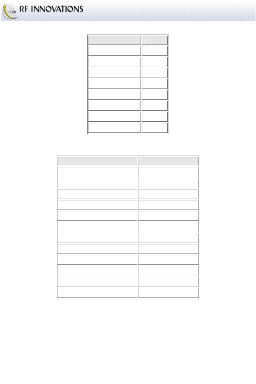
Appendix D Factory Defaults
RFI-9256 Radio Modem User Manual Page 94 of 96
Value Default
Baud 19200
Parity None
Data Bits 8
Stop Bits 1
Flow Control Disabled
Tx Packetiser Timer Disabled
Tx Packetiser Timer Disabled
Rx Buffer Limit 3072
Table 42: Serial port default settings
Value Default
DCD Mode ONLINE controls DCD
CTS Mode CTS disabled
Auxiliary I/O Sample Time 500ms
Auxiliary I/O follows Remote Disabled
Auxiliary I/O Enabled
Auxiliary I/O Direction All inputs
Auxiliary I/O Powerup Defaults All high
Event Log Level General Information
Unit Name None
Security Code None
Menu Password None
Menu Timeout 15 Minutes
Table 43: Other default settings
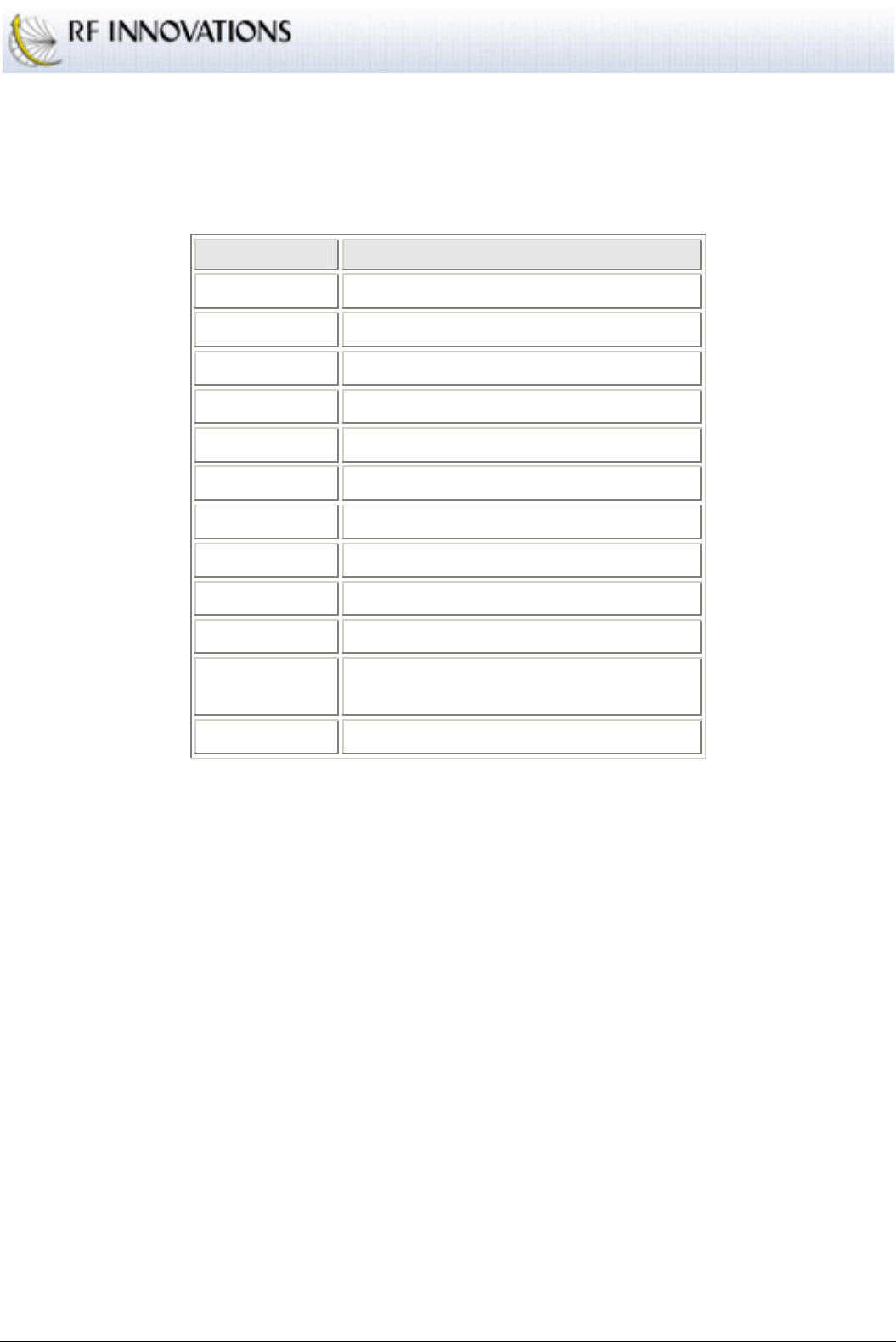
Appendix E Glossary
RFI-9256 Radio Modem User Manual Page 95 of 96
Appendix E Glossary
Table 44 contains the terms, acronyms, and abbreviations used in this document.
Term Description
BER Bit Error Rate
CRC Cyclic Redundancy Check
DCE Data Communications Equipment
DTE Data Terminal Equipment
EIRP Effective Isotropic Radiated Power
FDD Frequency Division Duplex
FHSS Frequency Hopping Spread Spectrum
ISM Industrial Scientific Military
PSTN Public Switched Telephone Network
RSSI Receive Signal Strength Indication
SCADA Supervisory Control and Data
Acquisition
TDD Time Division Duplex
Table 44: Terms, acronyms, and abbreviations

Appendix E Glossary
RFI-9256 Radio Modem User Manual Page 96 of 96
Index
Applications ....................................................................... 36
Basic Point-to-point Network........................................ 36
Broadcast Network........................................................ 39
Broadcast Network with Back-to-back Repeaters ......... 40
Dial-up Networking with Back-to-back Repeaters........ 42
Hayes Dial-up Auxiliary I/O ......................................... 50
Hayes Dial-up Networking............................................ 41
Multiple Slave Point-to-point Network ......................... 37
Point-to-point Auxiliary I/O .......................................... 48
Point-to-point Auxiliary I/O with a Back-to-back
Repeater.................................................................... 49
Point-to-point Network with Back-to-back Repeaters... 38
SCADA Network with a Back-to-back Repeater .......... 46
SCADA Network with Routing Table........................... 44
Simplex Point-to-point Network.................................... 36
Configuration ....................................................................... 7
Front Panel Interface ..................................................... 10
Hayes AT Command Interface........................................ 8
Terminal Menu Interface................................................. 7
User Interfaces................................................................. 7
Factory Defaults................................................................. 93
Glossary.............................................................................. 95
Hayes AT Command Reference......................................... 75
‘%’ Register Commands................................................ 87
Other Commands........................................................... 88
Radio Commands .......................................................... 75
S-Register Commands................................................... 80
Summary of Commands................................................ 88
Installation............................................................................ 6
RFI-9256 Location .......................................................... 6
Using the External Antenna ............................................ 6
Introduction.......................................................................... 5
Operation............................................................................ 14
Auxiliary I/O ................................................................. 35
Protocol Operation ........................................................ 26
Radio Operation ............................................................ 17
Serial Port Operation..................................................... 14
Product Overview ................................................................ 5
Technical Specifications .................................................... 51
Back-to-back Repeater Connector................................. 53
Case Dimensions........................................................... 56
Connector Pin Assignments .......................................... 52
Power Supply Notes...................................................... 54
Radio Specifications...................................................... 51
Version Numbering Scheme ......................................... 54
Terminal Menu Reference.................................................. 57
(C) Configure Protocol Menu........................................ 64
(D) Diagnostics Menu ................................................... 72
(L) Protocol Port Selection Menu.................................. 62
(M) Radio and I/O Configuration Menu ....................... 69
(R) Radio Configuration Menu ..................................... 58
(S) Serial Port Configuration Menu .............................. 67