STI Engineering RFI450H UHF DIGITAL MOBILE RADIO User Manual Crescendo UHF Half Duplex
STI Engineering Pty Ltd UHF DIGITAL MOBILE RADIO Crescendo UHF Half Duplex
User Manual
CRESCENDO UHF HALF-DUPLEX
USER MANUAL

Contents
Crescendo UHF Half-Duplex User Manual Page 2 of 78
Crescendo UHF Half-Duplex
User Manual
DISCLAIMER
© 2013 RF Innovations Pty Ltd. All rights reserved.
RF Innovations reserves the right to make improvements on the product in this manual at any time without
notice.
No part of this manual may be produced, copied, translated, or transmitted in any form or by any means
without the written permission of RF Innovations.
Information provided in this manual is intended to be accurate and reliable. However, RF Innovations
assumes no responsibility for its use or infringements upon the rights of third parties that may result from its
use.
Reference No. MAN00137
Revision 2.14
November 2013
Firmware Revision 1.8

Contents
Crescendo UHF Half-Duplex User Manual Page 3 of 78
Contents
1. Introduction ............................................................................................................................................................................. 6
2. Installation ................................................................................................................................................................................ 7
2.1 General considerations ......................................................................................................................................................... 7
2.2 External antennas ................................................................................................................................................................. 7
2.3 Safety and Compliance.......................................................................................................................................................... 8
2.3.1 Human Exposure to Emissions .................................................................................................................................... 8
2.3.2 Modifications............................................................................................................................................................... 8
3. Configuration ........................................................................................................................................................................... 9
3.1 Overview ............................................................................................................................................................................... 9
3.2 Cruise Control .................................................................................................................................................................... 10
3.2.1 Installation ................................................................................................................................................................. 10
3.2.2 Connecting to a Local Device ................................................................................................................................... 10
3.2.3 Saving and Loading Configurations .......................................................................................................................... 11
3.3 Terminal Menu Interface .................................................................................................................................................... 11
3.4 Hayes AT Command Interface ............................................................................................................................................ 12
3.5 Front Panel Interface .......................................................................................................................................................... 13
3.5.1 Radio Status LEDs (Mode 1)..................................................................................................................................... 13
3.5.2 RSSI, Tx Power, Temperature Status (Mode 2, 3, 4) ................................................................................................ 14
3.5.3 Main Serial Port Status (Mode 5) .............................................................................................................................. 14
4. Serial Port Operation ............................................................................................................................................................ 16
4.1 Overview ............................................................................................................................................................................. 16
4.2 Configuration ...................................................................................................................................................................... 17
4.3 Advanced Features .............................................................................................................................................................. 17
4.3.1 Control Lines ............................................................................................................................................................. 17
4.3.2 Packetiser Timers ...................................................................................................................................................... 18
4.4 Statistics .............................................................................................................................................................................. 19
5. Radio Operation..................................................................................................................................................................... 21
5.1 Data-Driven Mode .............................................................................................................................................................. 21
5.2 Packet-Driven Mode ........................................................................................................................................................... 21
5.2.1 Data Path ................................................................................................................................................................... 22
5.3 Radio Parameters ............................................................................................................................................................... 23
5.3.1 Addressing ................................................................................................................................................................. 23
5.3.2 Tx Power ................................................................................................................................................................... 24
5.3.3 RSSI Trip ................................................................................................................................................................... 24
5.3.4 Channel Selection ...................................................................................................................................................... 24
5.3.5 Retries ........................................................................................................................................................................ 25
5.4 Network Architecture .......................................................................................................................................................... 26
5.4.1 Network Topology .................................................................................................................................................... 26
5.4.2 Network Address ....................................................................................................................................................... 27
5.4.3 Store-and-forward Repeater ...................................................................................................................................... 28
5.5 Routing ................................................................................................................................................................................ 29
5.5.1 Network Structure ..................................................................................................................................................... 29
5.5.2 Routing Table ............................................................................................................................................................ 30
5.6 Diagnostics ......................................................................................................................................................................... 31

Contents
Crescendo UHF Half-Duplex User Manual Page 4 of 78
5.6.1 Data Quality .............................................................................................................................................................. 31
5.6.2 RSSI .......................................................................................................................................................................... 31
5.6.3 Monitor RSSI ............................................................................................................................................................ 31
5.6.4 PRBS Generator ........................................................................................................................................................ 31
5.6.5 Statistics .................................................................................................................................................................... 31
6. Protocol Operation ................................................................................................................................................................ 34
6.1 Overview ............................................................................................................................................................................. 34
6.2 Data Driven Protocol.......................................................................................................................................................... 34
6.3 Point-to-point Protocol ....................................................................................................................................................... 35
6.4 Point-to-multipoint Protocol ............................................................................................................................................... 35
6.4.1 Strict and Relaxed Addressing .................................................................................................................................. 35
6.4.2 Local Mode................................................................................................................................................................ 36
6.5 Hayes Dial-up Protocol ...................................................................................................................................................... 36
6.5.1 Dialling ...................................................................................................................................................................... 36
6.5.2 Answering ................................................................................................................................................................. 37
6.5.3 Escape Sequence ....................................................................................................................................................... 37
6.5.4 Hanging Up ............................................................................................................................................................... 37
6.5.5 DTR Modes ............................................................................................................................................................... 38
6.5.6 Traceroute .................................................................................................................................................................. 38
6.6 Modbus RTU Protocol ........................................................................................................................................................ 39
6.6.1 Modbus Queries ........................................................................................................................................................ 39
6.7 Distributed Network Protocol (DNP) ................................................................................................................................. 40
6.8 Datagram Protocol ............................................................................................................................................................. 40
6.9 RF Link Status ..................................................................................................................................................................... 41
6.10 Protocol to Radio Address Mapping .............................................................................................................................. 42
6.11 Multiple Protocol Modes ................................................................................................................................................ 43
7. Applications ............................................................................................................................................................................ 44
7.1 Point-to-point Networks ...................................................................................................................................................... 44
7.1.1 Basic Point-to-point Network .................................................................................................................................... 44
7.1.2 Multiple Port Point-to-point Network ....................................................................................................................... 45
7.1.3 Multiple Destination Point-to-point Network ............................................................................................................ 46
7.1.4 Point-to-point Network with Repeater....................................................................................................................... 47
7.2 Point-to-multipoint Networks .............................................................................................................................................. 48
7.2.1 Basic Point-to-multipoint Network ........................................................................................................................... 48
7.2.2 Point-to-multipoint Network with Roaming Remote ................................................................................................ 49
7.3 Hayes Dial-up Networks ..................................................................................................................................................... 50
7.3.1 Basic Hayes Dial-up Network ................................................................................................................................... 50
7.3.2 Hayes Dial-up Network with Repeaters .................................................................................................................... 51
7.4 Modbus/DNP Networks....................................................................................................................................................... 52
7.4.1 Basic Modbus RTU Network with Repeater ............................................................................................................. 52
7.4.2 Modbus with Modbus Query Enabled ....................................................................................................................... 53
7.4.3 DNP Network with Repeater ..................................................................................................................................... 54
7.5 Datagram Networks ............................................................................................................................................................ 55
7.5.1 Basic Datagram Network .......................................................................................................................................... 55
Appendix A Technical Specifications ..................................................................................................................................... 56
A.1 Type Approvals ............................................................................................................................................................... 56
A.2 Radio Modem Specifications .......................................................................................................................................... 56

Contents
Crescendo UHF Half-Duplex User Manual Page 5 of 78
A.2.1 Input Current ............................................................................................................................................................. 57
A.3 Connector Pin Assignment ............................................................................................................................................. 58
A.3.1 Main Serial Port ......................................................................................................................................................... 58
A.3.2 Auxiliary Serial Port .................................................................................................................................................. 58
A.3.3 I/O Module ................................................................................................................................................................ 59
A.3.4 Mounting Plate Dimensions ...................................................................................................................................... 61
Appendix B Management Reference ...................................................................................................................................... 62
B.1 Main Configuration ........................................................................................................................................................ 62
B.2 Radio Configuration ....................................................................................................................................................... 62
B.3 Link Control Configuration and Diagnostics ................................................................................................................. 64
B.4 Serial Port Configuration and Diagnostics .................................................................................................................... 64
B.5 Protocol Mode Configuration and Diagnostics ............................................................................................................. 65
B.6 Diagnostics ..................................................................................................................................................................... 66
Appendix C Hayes Reference .................................................................................................................................................. 67
C.1 General Commands ........................................................................................................................................................ 67
C.2 Connection Management Commands ............................................................................................................................. 68
C.3 I-Registers ...................................................................................................................................................................... 68
C.4 S-Registers ..................................................................................................................................................................... 69
C.5 R-Registers ..................................................................................................................................................................... 72
Appendix D Factory Defaults .................................................................................................................................................. 73
Appendix E Product Identification Table .............................................................................................................................. 75
Appendix F Glossary ............................................................................................................................................................... 76
Introduction
Crescendo UHF Half-Duplex User Manual Page 6 of 78
1. Introduction
Crescendo is a series of data-driven and packet-driven radio modems for high-speed data applications.
This manual is specific to Crescendo UHF Half-Duplex. Some of the relevant features of this model include:
UHF band operation (390 MHz - 500 MHz), with
approximately 20 MHz switching bandwidth (model
specific).
5 W (+ 37 dBm) maximum transmit power
Wideband or narrowband channels, with software
selectable frequency raster
Raw air rate 19.2 kbit/s (wideband) or 9.6 kbit/s
(narrowband)
Half-duplex data-driven or packet-driven operation with
Automatic Repeat Request (ARQ)
Windows GUI for configuration and diagnostics
(Cruise Control)
Internal configuration menu with diagnostic and
statistical information
LED front panel user interface
Two RS-232 serial ports (main and auxiliary)
Operating voltage 9 to 16 VDC
Type Approvals:
AS-4295
FCC
Industry Canada
ETSI (planned)
Integrated I/O module (model specific)
Channels
Channel width
(Channel spacing)
Occupied
bandwidth
Narrowband
12.5 kHz
< 7.25 kHz
Wideband
25 kHz
< 10.7 kHz
Table 1: Channel width

Installation
Crescendo UHF Half-Duplex User Manual Page 7 of 78
2. Installation
2.1 General considerations
There are a number of rules to observe when installing a Crescendo.
Antenna selection is vital to a good RF link. Different antennas are required depending on the application.
Please contact your antenna manufacturer or RF Innovations for correct antenna selection.
Antenna placement has a significant impact on RF link performance. In general, higher antenna placement
results in a better communication link. A vantage point should be chosen to clear the propagation ellipsoid.
An unobstructed, line-of-sight link will always perform better than a cluttered or obstructed link.
Obstructions, such as walls and poles, will distort the antenna radiation pattern and VSWR, resulting in less
efficient transmission and reception.
Antennas in close proximity are potential sources of mutual interference. A transmitter can cause overload of
a nearby receiver, if due precautions are not taken in antenna location. Moreover, transmitters in close
proximity may cause intermodulation. Slight adjustments in antenna placement may help solving
interference problems.
All items of radio equipment, such as antennas, are sources of RF radiation. They should thus be placed
away from electrical equipment, such as computers, telephones or answering machines.
Serial cable runs between radio modem and attached terminal equipment (eg RTU or PC) should be kept as
small as possible. A maximum cable capacitance of 2,400 pF is recommended for transfer rates up to 19.2
kbit/s. If a non-shielded, 30 pF / foot cable is used, the maximum length should be limited to 80 feet
(approximately 24m). For higher interface speeds, the length of the serial cable should be shortened.
Long serial cables should also be avoided in areas with frequent lightning activity or static electricity build-
up. Nearby lightning strikes or high levels of static electricity may lead to interface failure.
RF Innovations supplies a range of external data interface converters for applications requiring long cable
runs.
2.2 External antennas
Long antenna feed lines cause RF loss, both in transmission and reception levels, and degrade link
performance. When long cable runs are required use a suitable low-loss cable.
As an example, RG58 (tinned-copper braid) will exhibit a loss of 7.1 dB / 30 m at 148 MHz – 174 MHz,
whereas RG58 CellFoil will exhibit 3 dB less (4.2 dB / 30 m).
Antennas should not be located within close reach of people, due to radiation hazard. Exposure guidelines
should be followed at all times.
Use extreme caution when installing antennas and follow all instructions provided. Because external
antennas are subject lightning strikes, RF Innovations recommends protecting all antennas against lighting
strike by using lightning surge arrestors.

Installation
Crescendo UHF Half-Duplex User Manual Page 8 of 78
2.3 Safety and Compliance
2.3.1 Human Exposure to Emissions
To limit human exposure, the following guidelines should be observed:
1. Take reasonable precautions in any installation to maintain a clearance of no less than 2 m (two
metres) from the antenna to any person.
2. Do not apply power to the device unless the clearance described in 1 above has been allowed.
The guidelines above apply when transmitting at maximum power, with an antenna gain of up to 13 dB.
Note: This equipment has been tested and found to comply with the limits for a Class A digital device,
pursuant to part 15 of the FCC Rules. These limits are designed to provide reasonable protection against
harmful interference when the equipment is operated in a commercial environment. This equipment
generates, uses, and can radiate radio frequency energy and, if not installed and used in accordance with the
instruction manual, may cause harmful interference to radio communications. Operation of this equipment in
a residential area is likely to cause harmful interference in which case the user will be required to correct the
interference at his own expense.
For further information on human RF exposure, contact your local health department. For example, Health
Canada’s Safety Code 6 provides a comprehensive set of guidelines.
2.3.2 Modifications
CAUTION: Changes or modifications not expressly approved by RF Innovations may void the user’s
authority to operate the equipment legally, as well as any warranty provided.

Configuration
Crescendo UHF Half-Duplex User Manual Page 9 of 78
3. Configuration
3.1 Overview
The Crescendo provides five user interfaces that allow the radio to be configured and its performance to be
monitored:
1. Cruise Control management interface: All radio configuration and diagnostics parameters can be
accessed using the Windows-based Cruise Control Graphical User Interface (GUI).
2. Terminal menu interface: A menu system is available on both of the Crescendo’s serial ports. This
menu interface can be accessed through any terminal emulation program, such as RFI InTerm,
which can be downloaded from http://www.rfinnovations.com.au.
3. AT command interface: The AT command interface can be used to configure the Crescendo
through ASCII Hayes attention commands. This can be used to read and adjust the Crescendo
configuration and read performance parameters.
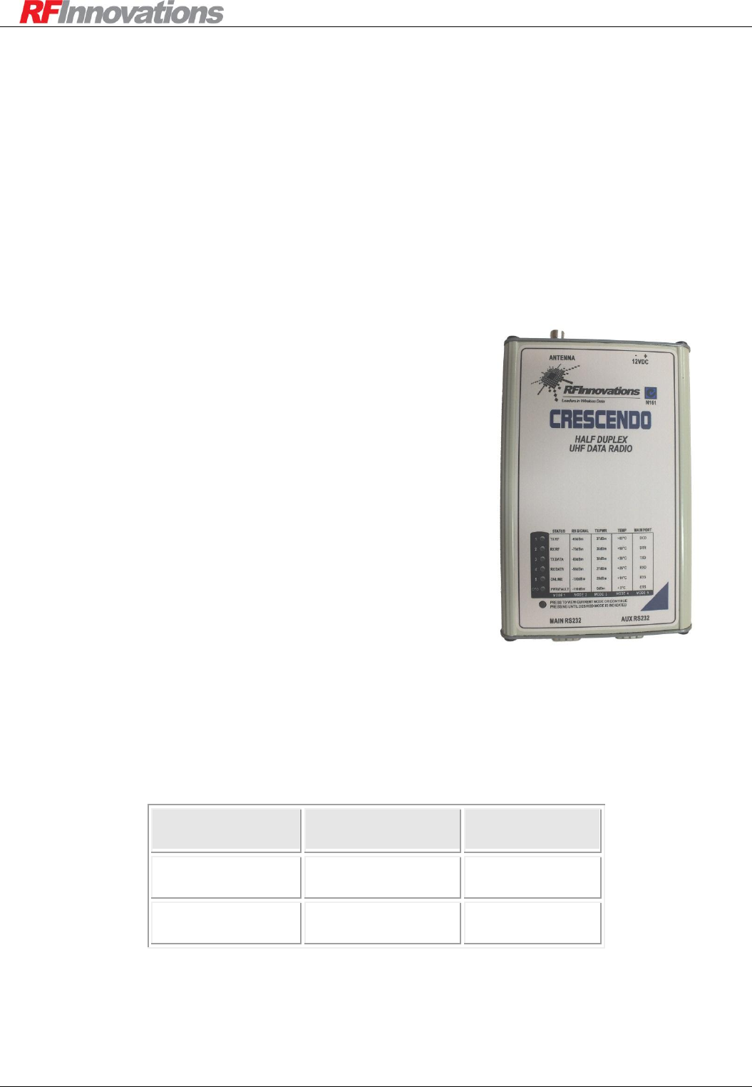
4. Front panel interface: The front panel interface consists of six dual colour (red / green) LEDs and a
push button. This panel can display the radio status, RSSI, configured transmit power, temperature,
and serial port status.
5. Digital input interface: The digital input pins may be used to configure the currently active channel.
See section 5.3.4.
Configuration
Crescendo UHF Half-Duplex User Manual Page 10 of 78
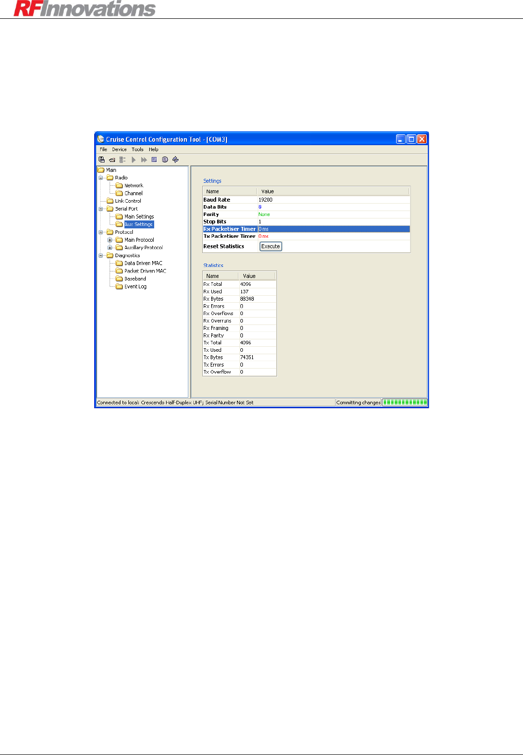
3.2 Cruise Control
The following sections briefly outline how to use Cruise Control with the Crescendo. For more information,
see the Cruise Control Manual. Figure 1 below is a typical screenshot of the Cruise Control Configuration
Tool.
Figure 1: Cruise Control Configuration Tool
3.2.1 Installation
The requirements for using the Cruise Control application are:
Pentium III+ Windows based machine.
At least 1 available serial port.
The Cruise Control application is provided on a CD, and runs with a self-installer.
3.2.2 Connecting to a Local Device
In order to connect to a local device, connect the auxiliary port of the Crescendo to a serial port on the PC
running Cruise Control. Configure Cruise Control with the appropriate serial port settings (19200 8N1 by
default).
Use the Device -> Connect to Local Device menu item to connect to the local device. Once all the
settings have been downloaded from the device, the available configuration groups are displayed in a tree on
the left. The items that can be configured in each group are displayed in tables on the right.
The names of editable items are displayed in black. Read only items have their names in grey.

Configuration
Crescendo UHF Half-Duplex User Manual Page 11 of 78
Changes made to the configuration or protocol mode of the serial port which Cruise Control is using do not
take effect immediately. They take effect when the disconnect button in Cruise Control is pressed, or the
radio is reset.
The main port of the Crescendo is typically used for data, but may also be used for Cruise Control if it is
configured in Hayes protocol.
It is possible to remotely connect to a device over the air by using Device -> Connect to Remote
Device and entering the remote address of the device. For best results when using a remote connection:
Do not connect to a remote device through store-and-forward repeaters.
Do not connect to a remote device while a live system is running.
3.2.3 Saving and Loading Configurations
The current configuration of a device can be saved by selecting:
File -> Save As...: This saves the configuration of the connected device to a selected file.
The configuration can later be re-applied to a device by using the File -> Upload option or
viewed using Tools -> View Saved Configuration.
It is recommended that only local devices have their configuration loaded from file. Performing this
operation on a remote device updates only those items that can be edited remotely.
3.3 Terminal Menu Interface
The terminal menu provides access to all configuration parameters in the radio. There are two methods to
access the terminal menu:
Execute the AT? command at the Hayes AT command interface. See section 3.4 on page 12 for
information on executing AT commands. The terminal menu will not be started when it is open on
another port, or a Hayes dial-up connection is established. In either case the BUSY response is
returned.
Select mode 6 on the front panel interface. See section 3.5 on page 13 for information on selecting
front panel modes. This will always result in the menu being opened on the auxiliary port, at 19200
8N1.
Changes made to the configuration or protocol mode of the serial port which the terminal menu is using do
not take effect immediately. They take effect when the radio is reset.
A full terminal menu reference can be found in Appendix B on page 62.
Configuration
Crescendo UHF Half-Duplex User Manual Page 12 of 78
3.4 Hayes AT Command Interface
The Crescendo radio supports Hayes ATtention commands. These are used to query radio configuration and
performance parameters, set radio configuration, and establish communication links between radios over the
air.
For a port to accept AT commands it must be first in local command mode. See section 6.5.3 on page 37 for
information on enabling and disabling local command mode.
The format for the query and configuration AT command is:
ATxxx<[I1, I2, … In]><=value><TERM>
Where:
AT is the attention code. All AT commands must be prefixed with AT. This is case insensitive, so
At, aT, or at can also be used.
xxx is the actual command. The list of valid AT commands is given in 0 on page 66.
<[I1, I2, … In]> is an optional section that allows the specification of an index. Indexes are
used to access one of an array of similar items. For example, the Crescendo radio has two serial
ports which can both have different configurations. The command ATS52[0]=1004 set the point-
to-point destination on the main port, while the command ATS52[1]=1004 will set the point-to-
point destination on the auxiliary port.
<=value> is an optional section that is used to set the value of a configuration parameter. If this
section is omitted, then the value of the configuration parameter will be displayed.
<TERM> is the terminator for the AT command. A terminator can consist of a carriage return
(ASCII value 13D) or a carriage return followed by a line feed (ASCII value 10D).
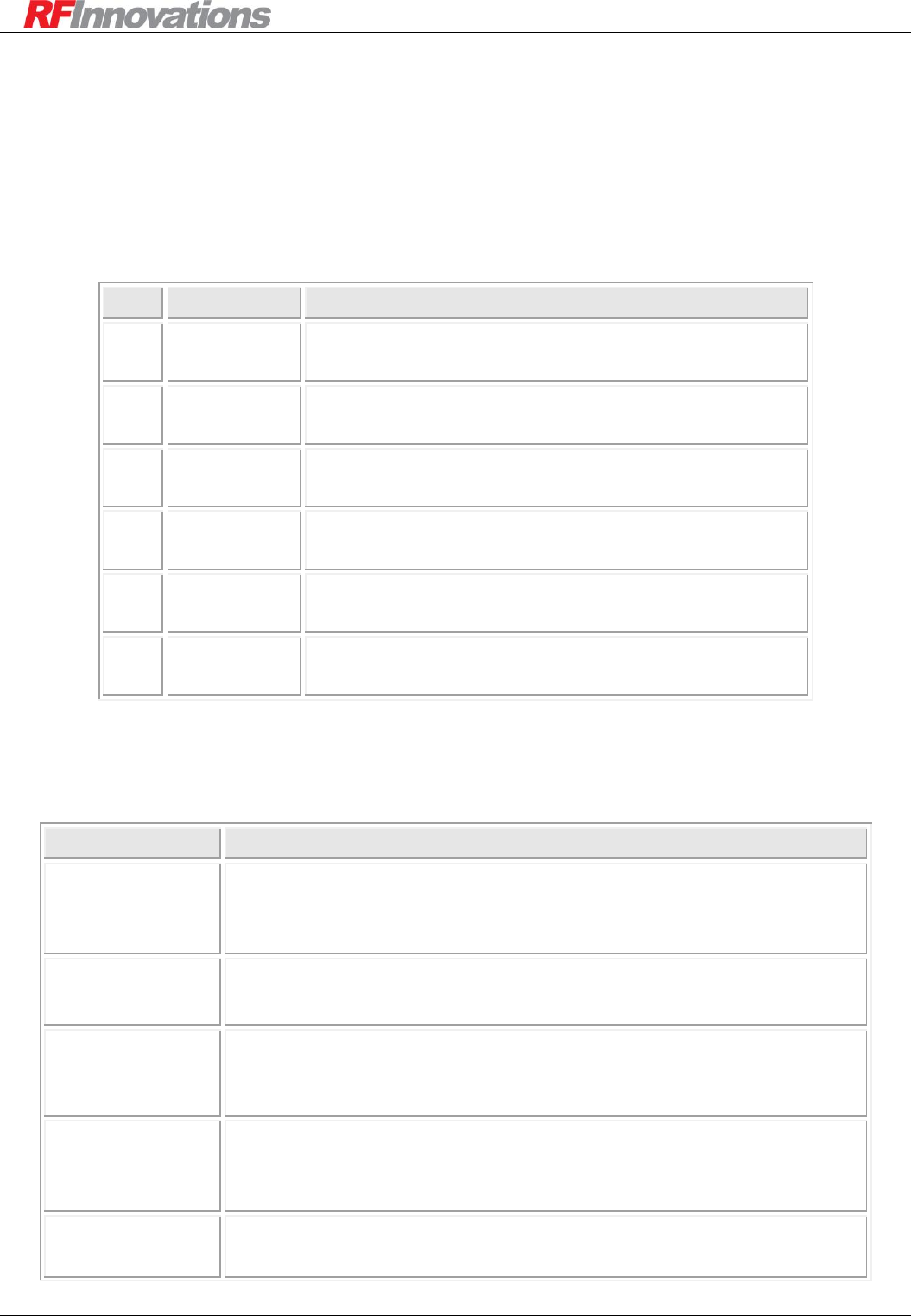
For each AT command that is issued a response is generated. The list of responses to AT commands is
shown in Table 2.
Response
Code
Response
Number
Description
OK
0
Returned whenever a command is entered that is executed correctly.
CONNECT
1
Returned whenever a connection is established with a remote unit.
RING
2
Returned whenever this unit is dialled by a remote unit.
NO
CARRIER
3
Returned whenever a connection fails to be established, or is dropped while it
is operating.
ERROR
4
Returned whenever a command is invalid or could not be executed.
BUSY
7
Returned whenever an attempt is made to dial a remote unit and that unit
already has a connection established, or an attempt is made to enable the menu
via AT? but the menu system is already enabled on the other serial port.
NO
ANSWER
8
Returned whenever an attempt is made to dial a remote unit, and that unit fails
to answer.
Table 2: AT command response codes
Configuration
Crescendo UHF Half-Duplex User Manual Page 13 of 78
3.5 Front Panel Interface
The front panel interface allows for real-time monitoring of radio parameters without external equipment.
The front panel can also be used to enable the menu on the Crescendo’s auxiliary port regardless of the
current serial port configuration.
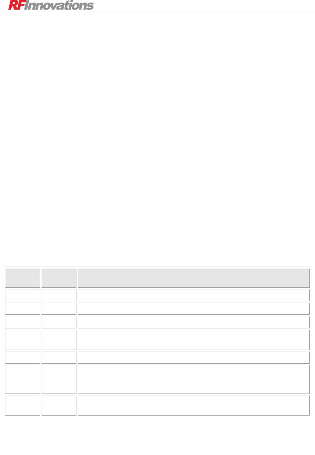
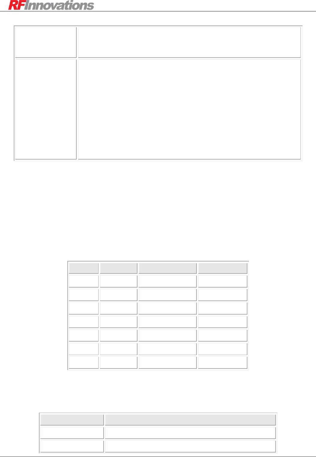
There are six front panel modes. To select a front panel mode, press the front panel button. The current panel
mode is shown by lighting a single red LED. To select another front panel mode, continue to hold the button
until the LED scrolls down to the appropriate mode, then release. The list of modes is shown in Table 3.
LED
Mode
Function
1
Radio Status
Section 3.5.1 on page 13 describes the functionality of the
LEDs when in radio status mode.
2
RSSI
Displays the current RSSI as a bar graph. Table 5 shows
the level for each bar item.
3
Transmit
Power
Displays the configured transmit power as a bar graph.
Table 5 shows the level for each bar item.
4
Temperature
Displays the internal temperature as a bar graph. Table 5
shows the level for each bar item.
5
Serial Port
Shows the main serial port status. The meaning of each
individual LED is shown in Table 6.
6
Configuration
Enables the terminal menu on the auxiliary port at 19200
8N1. The LED display is the same as mode 1.
Table 3: Front panel modes
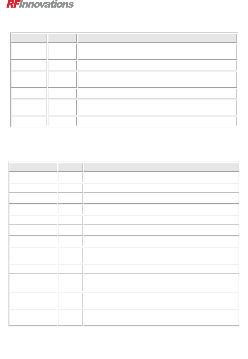
3.5.1 Radio Status LEDs (Mode 1)
LED
Description
(1) Tx RF Data
Flashes green when RF data is transmitted.
Flashes red when an RF user or Tx Sync packet is discarded due to retries
being exhausted.
(2) Rx RF Data
Flashes green when RF data is received.
Flashes red when a received RF packet is discarded.
(3) Tx Serial Data
Flashes green when serial data is transmitted from the Crescendo on either
serial port. Flashes red with Rx RF Data when a RF packet is discarded
due to a Tx Serial buffer overrun.
(4) Rx Serial Data
Flashes green when serial data is received on either serial port.
Flashes red when a receive error occurs on either serial port. See section
4.4 on page 19 for serial statistics.
(5) Online
Solid green if packets addressed to the unit has been received. The
duration the LED stays green is set by the Online Timeout.
Configuration
Crescendo UHF Half-Duplex User Manual Page 14 of 78
Solid green when a connection is established with a remote radio.
Flashes red when a point-to-point link goes from the connected to not
connected state.
(6) Power / Fault
Flashes green when the radio is operating normally.
Flashes red when a fault has occurred. Faults are displayed in Cruise
Control under Main -> Diagnostics -> Faults. Faults that are
detected by the radio are:
Point-to-point destination address equal to source address
Reserve section of a datagram packet not equal to 0x0000.
The last time the radio reset was due to a watchdog reset.
When a fault occurs, it is latched for 15 minutes. If after 15 minutes the
alarm has not re-occurred it is cleared. The fault can be cleared manually
by re-powering the radio.
Table 4: Mode 1 LED functions
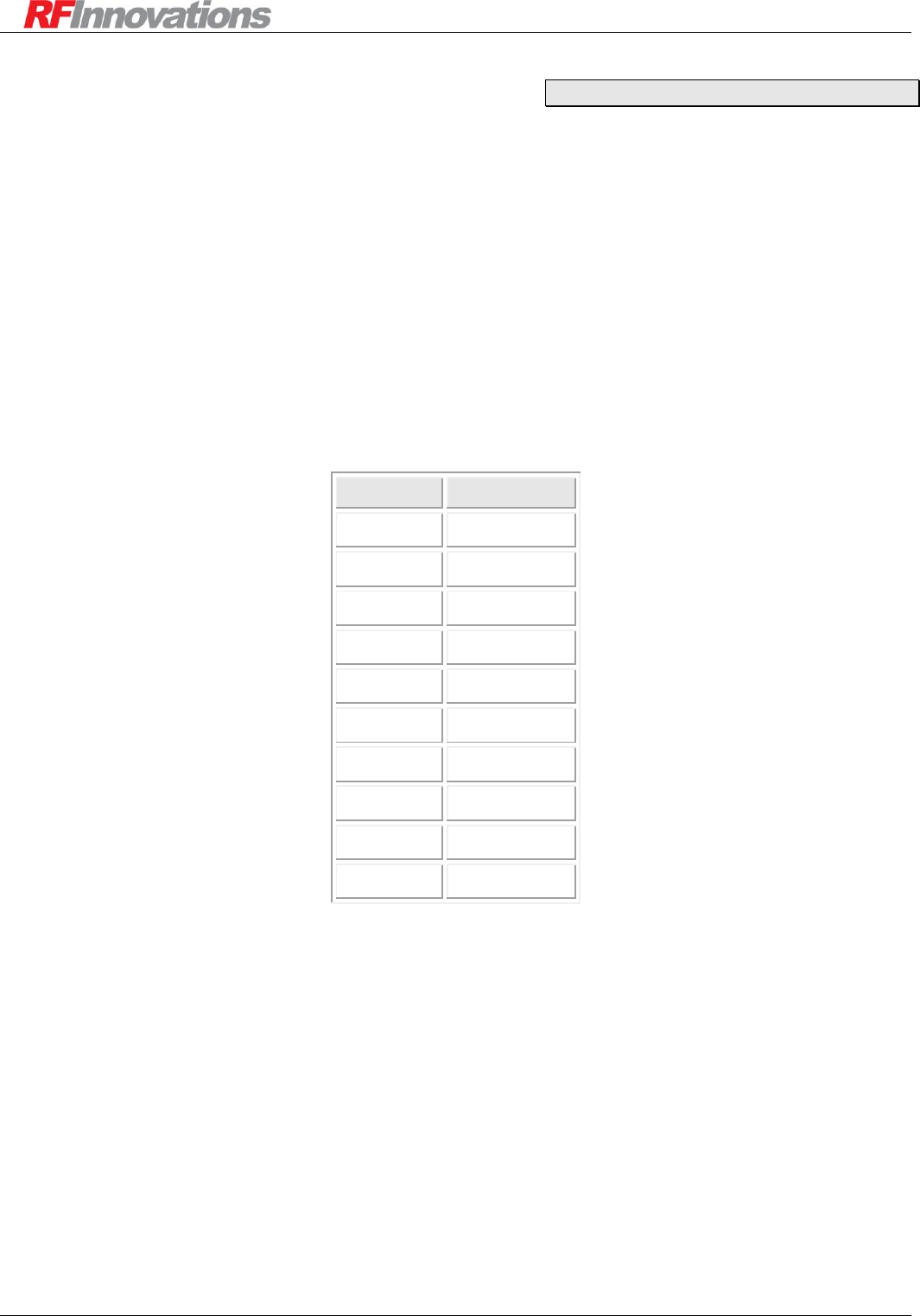
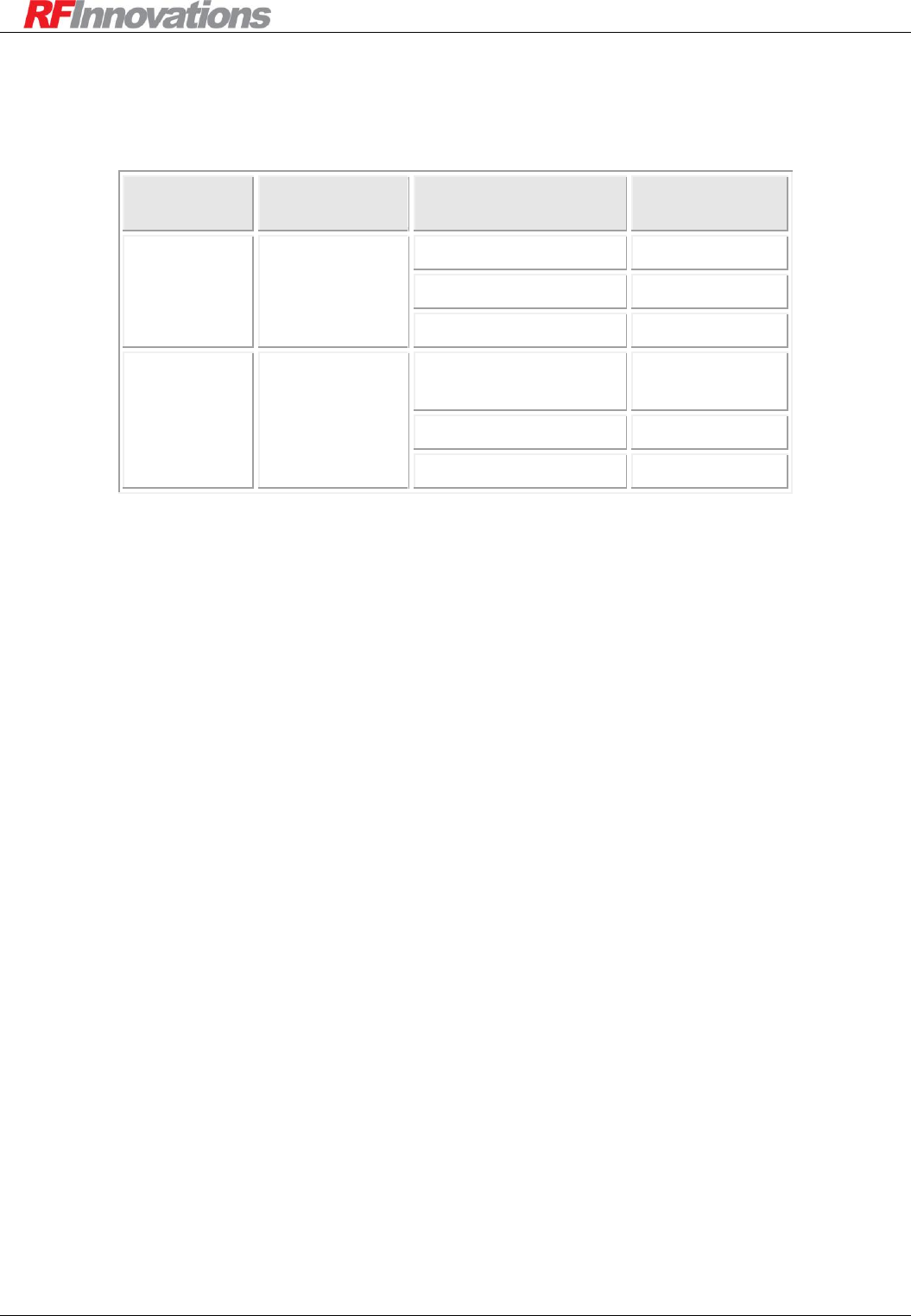
3.5.2 RSSI, Tx Power, Temperature Status (Mode 2, 3, 4)
When in mode 2, 3, or 4 the front panel is used as a bar graph, with the lowest value indicated by all LEDs
off, and the highest by all LEDs on. The bar grows by lighting LED 6 up to LED 1 green. If the top LED is
red, then it indicates that the current value is half way between the listed value and the previous value. Table
5 shows the levels for the bar graph display.
LED
RSSI
Transmit Power
Temperature
1
-60 dBm
+37 dBm
+62ºC
2
-70 dBm
+36 dBm
+50ºC
3
-80 dBm
+30 dBm
+38ºC
4
-90 dBm
+27 dBm
+26ºC
5
-100 dBm
+20 dBm
+14 ºC
6
-110 dBm
+0 dBm
+2 ºC
All Off
-120 dBm
Not Used
-10 ºC
Table 5: Front panel RSSI, transmit power, and temperature modes
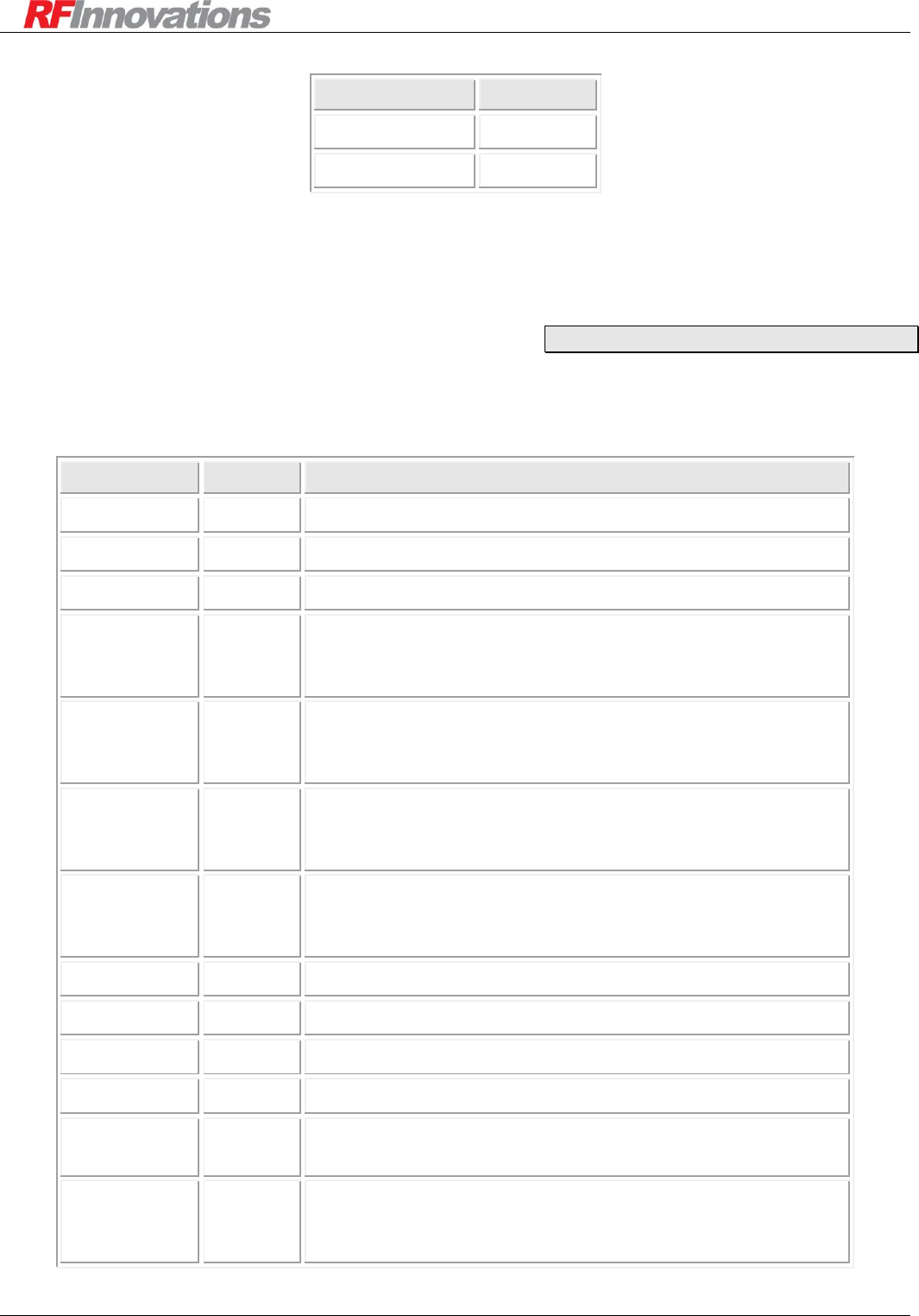
3.5.3 Main Serial Port Status (Mode 5)
LED
Description
(1) DCD
Green when the DCD output is low, red when it is high.
(2) DTR
Green when the DTR input is low, red when it is high.

Configuration
Crescendo UHF Half-Duplex User Manual Page 15 of 78
(3) Tx Serial Data
Flashes green when serial data is transmitted from the
Crescendo on either serial port.
(4) Rx Serial Data
Flashes green when serial data is received by the
Crescendo on either serial port.
Flashes red when a receive error occurs on either serial
port. See section 4.4 on page 19 for serial statistics.
(5) RTS
Green when the RTS input is low, red when it is high.
(6) CTS
Green when the CTS output is low, red when it is high.
Table 6: Mode 5 LED functions

Serial Port Operation
Crescendo UHF Half-Duplex User Manual Page 16 of 78
4. Serial Port Operation
4.1 Overview
The Crescendo radio has two DCE RS-232 serial ports with DB9 connectors. The serial port pin outs can be
found in Appendix A.3 on page 58.
The main port supports:
TX, RX, and GND.
RTS and DTR inputs.
CTS and DCD outputs.
While the auxiliary port supports:
TX, RX, and GND.
Both serial ports support over the air data transfer. In general, due to the presence of control lines, the main
port should be used as the main data port. The auxiliary port should be used for performance monitoring and
configuration.
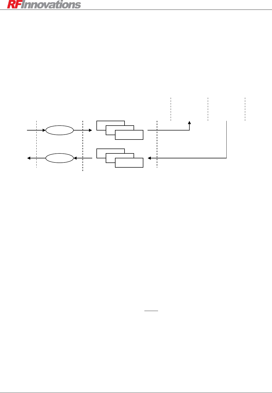
Both main and auxiliary serial ports have internal byte buffers on transmit and receive interfaces. This
configuration is shown in Figure 2.
4096 byte output buffer
TX Line (input from DTE)
RX Line (output to DTE)
Input to RF /
internal processing
Output from RF /
internal processing
4096 byte input buffer
Figure 2: Buffering scheme on the Crescendo
This serial port buffering scheme has a number of ramifications on the Crescendo operation:
No preamble is required to account for radio turn-on time.
If the data cannot be sent, it will be buffered until the transmitter is ready.
If the data terminal equipment (DTE) is not ready for data, the Crescendo can buffer the data until
the DTE is ready.
If the buffer is full, additional data received will be discarded until space has become available.

Serial Port Operation
Crescendo UHF Half-Duplex User Manual Page 17 of 78
4.2 Configuration
Both main and auxiliary serial ports support the following configuration options:
Baud rate: 300, 600, 1200, 2400, 4800, 9600, 19200, 38400, 57600 or 115200.
Data bits: 7 or 8
Parity: None, odd, or even
Stop bits: 1 or 2
4.3 Advanced Features
4.3.1 Control Lines
The main serial port has four control lines:
Ready to Send (RTS)
Clear to Send (CTS)
Data Terminal Ready (DTR)
Data Carrier Detect (DCD)
The main serial port supports hardware flow control using the RTS and CTS control lines. When hardware
flow control is enabled:
The radio will only transmit data to the DTE when the RTS line is high.
The radio will raise the CTS line when its input buffer is less than three quarters full, and drop the
CTS line when its input buffer is at least three quarters full.
NOTE: When hardware flow control is enabled, the CTS line configuration is ignored.
In addition to hardware flow control, the CTS and DCD lines can be configured to behave in one of the
following ways:
Always High: The control line is always held high.
Always Low: The control line is always held low.
Mirrors DTR: The control line mirrors the state of the DTR input.
Mirrors RTS: The control line mirrors the state of the RTS input.
Follows Rx Carrier: The control line goes high when a valid carrier is detected and goes low when
the carrier stops.
Follows Tx Enable: The control line goes high when the transmitter is enabled and goes low when
the transmission is finished. This includes acknowledgements and retries when the radio is
operating in packet driven mode.
Follows Online: The control line goes high if a packet addressed to the unit has been received. The
duration the control line stays high is set by the Online Timeout. The Online Timeout can be
configured between 100 and 65535ms. The control line also stays high while a connection is
established with a remote radio.
DTR is used to control Hayes dial-up connections (see section 6.5.5 on page 38)
Main -> Serial Port
Main -> Serial Port -> Settings
Serial Port Operation
Crescendo UHF Half-Duplex User Manual Page 18 of 78
4.3.2 Packetiser Timers
Many protocols delimit packets of data by silence on the communications line for a set period of time. A
common example of such a protocol is Modbus.
Due to the framed structure over the air when the radio is in packet driven mode, packetiser timers should be
used to support protocols and increase the efficiency of data transmission. Packetiser timers can be set
between 0 and 10000ms.
The RX packetiser timer is used to detect the end of each packet. The Crescendo will only begin transmitting
data once the end of the packet has been detected. The suggested RX packetiser timer values for each serial
baud rate when using the radio in packet driven mode is given in Table 7.
For protocols such as ModBus, DNP3, and TDE, the RX packetiser timer should be set greater than
maximum delay between characters in the same packet. Table 7 can also be used as a guide.
Baud
RX Timer
300
>= 35ms
600
>= 18ms
1200
>= 10ms
2400
>= 6ms
4800
>= 4ms
9600
>= 3ms
19200
>= 2ms
38400
>= 2ms
57600
>= 2ms
115200
>= 2ms
Table 7: Packetisation timers for different baud rates
If the packet size is greater than the RX serial buffer size (4096 bytes), then RX packetiser timers should not
be used as the internal buffers will overflow, and bytes will be lost. Tx packetiser timers should be used
instead, and set to the suggested value given in Table 8.
When using the data driven protocol, it is recommended to use TX packetiser timers and data timeout, rather
than the RX packetiser timers, to maintain a low end-to-end latency.
Set the data timeout to the maximum delay between characters in the same packet. Suggested values
are given in Table 7. See section 6.2 for more information on the data timeout setting.
Set the TX packetiser timer to the maximum delay between RF blocks.
Suggested TX packetiser timer values are given in Table 8.
Main -> Serial Port -> Settings
Serial Port Operation
Crescendo UHF Half-Duplex User Manual Page 19 of 78
Channel Width
TX Timer
Narrowband
>= 25ms
Wideband
>= 13ms
Table 8: TX packetisation timers for different channel widths
Using packetiser timers will increase the latency induced by the radio system, as no part of the packet can be
transmitted until it has been fully received.
4.4 Statistics
Statistics are maintained for each serial port and these can be used to analyse and debug problems. The
statistics are given in Table 9.
Name
Number
Description
Rx Total
0
The size of the input buffer.
Rx Used
1
The number of bytes currently stored in the input buffer.
Rx Bytes
2
The total number of bytes that have been received.
Rx Errors
3
The total number of errors that have occurred during data
reception. This is the sum of Rx Overflows, Rx Overruns, Rx
Framing, and Rx Parity errors.
Rx Overflows
4
The total number of overflow errors that have occurred. An
overflow error occurs whenever data is received, but the
internal buffer is already full.
Rx Overruns
5
The total number of overrun errors that have occurred. An
overrun error occurs whenever the internal processor is
overloaded and cannot handle the incoming data.
Rx Framing
6
The total number of framing errors that have occurred.
Framing errors usually occur due to mismatched serial port
baud rates between the DTE and DCE.
Rx Parity
7
The total number of parity errors that have been detected.
Tx Total
8
The size of the output buffer.
Tx Used
9
The number of bytes currently stored in the output buffer.
Tx Bytes
10
The total number of bytes that have been transmitted.
Tx Errors
11
The total number of errors that have occurred while
transmitting. This is equal to the Tx Overflows count.
Tx Overflows
12
The total number of overflows that have occurred. An overflow
occurs when the radio attempts to insert data into the transmit
buffer internally, and the buffer is full.
Table 9: Serial port statistics
Main -> Serial Port -> Settings

Serial Port Operation
Crescendo UHF Half-Duplex User Manual Page 20 of 78
These statistics can be used to isolate a number of potential problems in a Crescendo system.
A large number of Rx framing errors indicates that the radio serial port configuration (baud, data
bits, parity, and stop bits) does not match the serial port configuration of the DTE.
A large number of Rx overflow errors indicate that the DTE is supplying data faster than it can be
transferred over the air.
A large number of Tx overflow errors indicate that data is arriving over the air faster than the DTE
can retrieve it from the radio.

Radio Operation
Crescendo UHF Half-Duplex User Manual Page 21 of 78
5. Radio Operation
This section describes the two modes of Crescendo operation: data and packet-driven. These modes underlie
the different protocols supported, described in section 6.
Regardless of the mode used serial characters are assembled in small blocks for the purpose of Forward
Error Correction (FEC). These blocks are then subject to error coding / interleaving, and protected by a
CRC. This operation is transparent to the user, with the advantage of added robustness in multipath fading
and noisy environments.
5.1 Data-Driven Mode
In data-driven mode many of the features that are available in the Crescendo are not utilised in order to
provide a serial transfer with minimum delay. In particular data driven mode does not utilise:
Unit addressing / repeaters
Retries / routing
Complex network structures / network address
Data driven mode provides a low latency broadcast network where any data presented on the main port of a
unit is immediately transmitted over the air, received by all units in range and transmitted out their main
ports.
Data-driven mode is used when the data driven protocol (see section 6.2) is selected on the main port. For all
other protocols the packet-driven mode is used.
5.2 Packet-Driven Mode
Packet-driven operation is based upon Automatic Repeat Requests (ARQ) with retries and exponential back-
off.
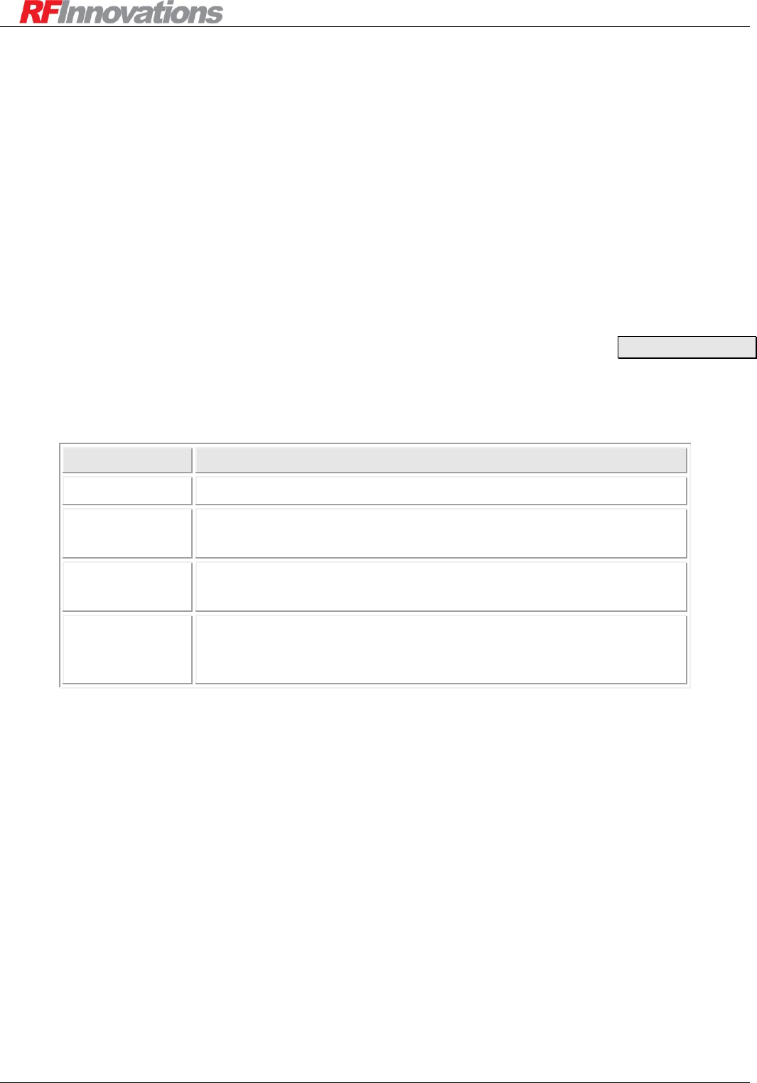
A transmission consists of a packet transmitted from source to destination, followed by an acknowledgement
from destination to source. Acknowledgements are done on an end-to-end basis, so intermediate repeaters
simply pass the packet and acknowledgement on. This is shown in Figure 3.
Repeater
Remote
Payload Packet
Base
Payload Packet
ACK
ACK
Figure 3: Packet driven with ARQ operation
Radio Operation
Crescendo UHF Half-Duplex User Manual Page 22 of 78
If a payload packet or ACK is lost, resulting in the base radio not receiving the ACK, the source radio
retransmits the payload packet. This continues until the number of retries for the packet has been exhausted.
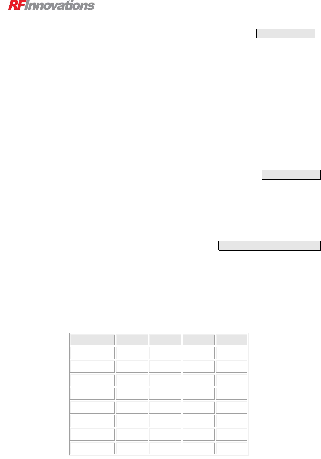
5.2.1 Data Path
Internally, the Crescendo stores a set of payload frames that are waiting to be transmitted, and a set of
payload frames that have been received but not yet processed. Combining this with the serial port interface
described in section 4 on page 16, an overall picture of the data path in the Crescendo radio can be obtained,
shown in Figure 4.
4096 byte output
buffer
4096 byte input buffer
outgoing frame buffers
incoming frame buffers
Tx Packet
Rx Packet
Figure 4: Overall data path in the Crescendo radio modem
Due to the framed structure over the air, and the data path shown above, the Crescendo cannot be regarded
as a direct wire replacement. It will induce additional latency in the communications link, as well as
potentially causing changes in the timing between bytes.
In addition, when the link is bad due to interference or low signal level, bytes can be lost when the number
of retries are exhausted.
LATENCY
The Crescendo will introduce latency into the system. This latency is caused by the following factors:
Serialisation delays: Serialisation delay is the time taken for the incoming RS-232 bit stream to be
converted back into bytes. The serialisation delay for each serial port can be calculated in
milliseconds using Equation 1.
baud
bits
tserial 1000
Equation 1: Latency induced by serialisation delay
Where bits is the number of bits in a byte (including start, stop and parity bits), and baud is the baud
rate of the serial port.
Thus, for 9600 baud, 8N1 the serialisation delay is around 1ms per serial port.
Switching delay: When the Crescendo is presented with data to send over the air, it switches from
receive to transmit mode and performs synchronisation tasks to prepare for the transmission of the
data. The time taken to do this is the switching delay.
Radio Operation
Crescendo UHF Half-Duplex User Manual Page 23 of 78
Link quality: The quality of a link can have a substantial impact on the latency induced by the
radio. The Crescendo will retry packets that become corrupted due to RF interference, configurable
between 0 and 20 retries. The more retries that are required to successfully transmit a packet, the
greater the latency induced. This is only applicable to packet driven mode.
Multiple protocols: When multiple protocols are used (including management with Cruise Control),
latency will be increased as extra protocol data is inserted into the data stream.
Repeaters: The addition of repeaters in a network will increase latency due to payload packets and
acknowledgements being transmitted multiple times before reaching their destination.
For systems that require low latency, the Crescendo has a data driven protocol which reduces many of the
delays mention above.
5.3 Radio Parameters
5.3.1 Addressing
Each radio in a Crescendo network has a unique 16-bit address. The address space is divided into sections as
shown in Table 10.
Address Range
Usage
0
Reserved.
1 – 61439
Singlecast addresses.
Each radio in a network must have a unique singlecast address.
61440 – 65534
Reserved.
These addresses are reserved for use in future Crescendo releases.
65535
Broadcast address.
This address is used when data transmitted is to be processed by all
radios. This address can only be used in the datagram packet header
Table 10: Crescendo address space
The singlecast radio address is used for routing traffic between units and determining the end points in a
communications link.
Only one singlecast address can be assigned to each radio, and each radio in a particular network must have
a unique address.
Main -> Radio
Radio Operation
Crescendo UHF Half-Duplex User Manual Page 24 of 78
5.3.2 Tx Power
The transmit power of the Crescendo can be configured to transmit at fixed levels into a 50 load:
0dBm (1 mW)
+20dBm (100 mW)
+27dBm (500 mW)
+30dBm (1W)
+36dBm (4W)
+37dBm (5W)
A maximum power setting can be configured by the distributor to limit the allowable power for a given
combination of radio and antenna.
5.3.3 RSSI Trip
The RSSI trip setting is the lowest RF signal level for which the radio modem will attempt to acquire data.
An RSSI trip can be thought of as a “receiver unsquelch”.
RSSI Trip is configurable between -120 dBm and -40 dBm.
5.3.4 Channel Selection
Crescendo has sixteen channels that can be configured. Each channel is comprised of an uplink / downlink
(or transmit / receive) frequency pair.
The channel frequencies can be set within the switching bandwidth of the radio. The supported channel
frequency rasters are determined by the type approval of the unit.
The active channel can be set by adjusting the current channel setting in software. In models with an I/O
module, if “I/O Selects Channel” is enabled then the channel may also be set via the I/O module as follows:
Channel
Pin 4
Pin 3
Pin 2
Pin 1
1
Gnd
Gnd
Gnd
Gnd
2
Gnd
Gnd
Gnd
N/C
3
Gnd
Gnd
N/C
Gnd
4
Gnd
Gnd
N/C
N/C
5
Gnd
N/C
Gnd
Gnd
6
Gnd
N/C
Gnd
N/C
7
Gnd
N/C
N/C
Gnd
8
Gnd
N/C
N/C
N/C
Main -> Radio
Main -> Radio
Main -> Radio -> Channel

Radio Operation
Crescendo UHF Half-Duplex User Manual Page 25 of 78
9
N/C
Gnd
Gnd
Gnd
10
N/C
Gnd
Gnd
N/C
11
N/C
Gnd
N/C
Gnd
12
N/C
Gnd
N/C
N/C
13
N/C
N/C
Gnd
Gnd
14
N/C
N/C
Gnd
N/C
15
N/C
N/C
N/C
Gnd
16
N/C
N/C
N/C
N/C
Table 11: Channel selection via I/O module
In the table above, “Gnd” indicates that the pin should be connected to ground, and “N/C” means that the pin
should not be connected. Note that channel 16 is selected by default when no pins are connected and “I/O
Selects Channel” is enabled. Also note that the order of the columns in this table matches the layout of pins
on the connector. See Appendix A.3.3 for a pin-out diagram.
In general, channels are numbered starting from 1. However, the Legacy Channel Numbering setting causes
channels to be indexed from 0 when selecting and configuring channels using Hayes commands only. See
Appendix C.4 for details.
5.3.5 Retries
The maximum number of retries per packet can be configured between 0 and 20. When a low number of
retries is selected, the link may become unreliable in the presence of interference or collisions. When a high
number of retries is selected, the link will be more reliable. However, additional retries will induce
substantial latency in the presence of interference.
Two parameters are used to set the number of retries to use:
Singlecast retries: The number of retries to use on data that is destined for a single receiving radio.
This is applied to any transmission using the point-to-point or Hayes dialup protocols.
If the remote unit is non-existent, due to a misconfigured destination address, the remote being out
of range, or the remote unit being faulty, the data will be retransmitted a number of times equal to
the singlecast retries setting. This can dramatically reduce the throughput of a radio network.
Broadcast retransmissions: The number of retries to use on data that is destined for multiple
radios. This is applied to any transmission when using the point-to-multipoint protocol, or to any
packet addressed to the broadcast address when using the datagram protocol.
When a unit is broadcasting data, the transmission cannot be acknowledged, as collisions would occur
between the acknowledgements. Instead, a broadcasting unit will transmit all data a fixed number of times
equal to the broadcast retransmissions parameter, and receiving units will discard any duplicate data
received.
Two parameters determine how long the Crescendo will wait for an acknowledgement after transmission
before retrying. These parameters are:
Main -> Radio -> Network
Radio Operation
Crescendo UHF Half-Duplex User Manual Page 26 of 78
Repeaters in Network: The maximum number of repeaters through which a packet must go before
reaching its destination. Note that depending on network topology, this may be less than the total
number of repeaters in the network. This parameter should be set the same for all units in the
network. The repeaters in network setting can be configured between 0 and 65535.
Max Packet Size: This is the maximum number of bytes of payload a packet will have. This
parameter should be set the same for all units in the network. The max packet size can be
configured between 0 and 4096 bytes. Setting Max Packet Size too low may cause fragmentation of
data transmitted over the air, negating the effect of Packetiser Timers (see section 4.3.2). However,
reducing Max Packet Size may reduce latency and improve throughput in a network with repeaters.
5.4 Network Architecture
5.4.1 Network Topology
The Crescendo has few restrictions on network topology, as there are no time division synchronisation
requirements. An example of a tree network topology is given below to help illustrate network concepts.
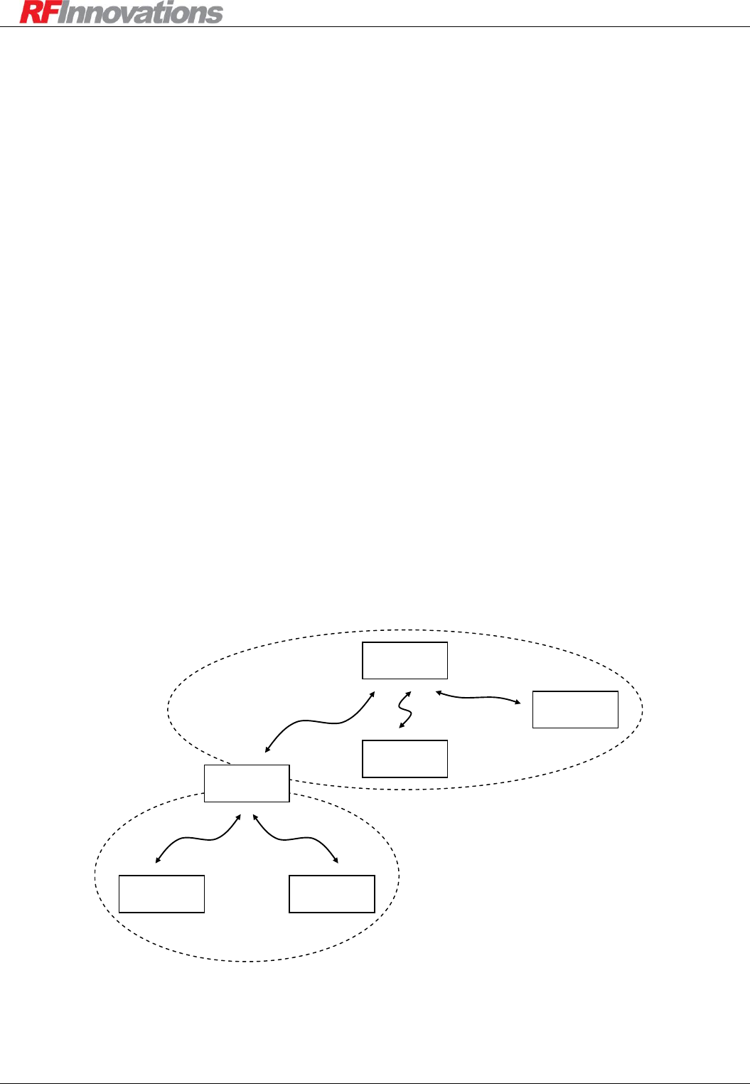
TREE NETWORK
A Crescendo network consists of a set of sub-networks (subnets). Each subnet has a single base or repeater
and any number of remotes.
1. Base subnet: The root of the tree, containing a unit not configured as a store-and-forward repeater.
2. Repeater subnet: A branch of the tree, containing a unit configured as a store-and-forward repeater.
These two types of subnet are shown in Figure 5.
Repeater Subnet
Base Subnet
Store-and-forward
Repeater
Base
Remote 2
Remote 4
Remote 3
Remote 1
Figure 5: Crescendo tree network topology
Radio Operation
Crescendo UHF Half-Duplex User Manual Page 27 of 78
When allocating radio addresses, a recommended convention is to reserve the first two decimal digits as the
subnet number, and the last three digits for individual radios residing within the subnet. For example,
consider the scenario shown in Figure 5, and the address allocation given in Table 12.
Subnet
Subnet
Address
Radio
Radio Address
Base subnet
1
Base
1000
Remote 1
1001
Remote 2
1002
Repeater
subnet
27
Store-and-forward
Repeater
27000
Remote 3
27001
Remote 4
27002
Table 12: Addressing for a tree network topology
Following this convention can reduce the complexity of implementing routing tables.
A subnet should not be confused with co-located networks (see section 5.4.2). All units on the base and
repeater subnets should have the same network address. For more on store-and-forward repeaters see section
5.4.3 on page 28.
5.4.2 Network Address
The network address is a high level address used to differentiate between co-located networks. For a unit to
send to or receive from another unit, their network addresses must match. A co-located network should not
be confused with a base or repeater subnet (see section 5.4.1)
Figure 6 shows an example of two co-located networks. In this example all units that are a part of network A
should have the same network address, and all units in network B should share a different network address.

Radio Operation
Crescendo UHF Half-Duplex User Manual Page 28 of 78
Base 1B
Remote 1B
Remote 1A
Remote 2A
Remote 2B
Network A
Network B
Base 1A
Figure 6: Co-located networks
When co-locating Crescendo networks it is important to observe the following:
If the co-located networks operate on different Tx and Rx frequencies, RF interference will not
occur. This is the ideal situation.
If the co-located networks share Tx or Rx frequencies, the networks must have different network
addresses. If they do not, units on one network could masquerade as units on the other network,
causing random errors including data loss and reception of erroneous messages.
Even with a different network address, the networks can cause interference with each other. This
could cause retries, resulting in increased latency, and possible data loss if retry counts are
exhausted.
5.4.3 Store-and-forward Repeater
A Crescendo unit may be configured to operate as a store-and-forward repeater (see Appendix B.1). A store-
and-forward repeater can be used to extend the range of a network. It behaves as a combination of base and
remote unit in the following manner:
If a packet is received over the air which is addressed to the repeater, the packet data will be
transmitted out the serial port.
If a packet is received over the air which is not addressed to the repeater, but with a next hop
address equal to the repeater’s address, the packet will be submitted for retransmission.
If a packet is received over the air which is addressed to the broadcast address, the packet will be
submitted for retransmission, and the packet data will be transmitted out the serial port.

Radio Operation
Crescendo UHF Half-Duplex User Manual Page 29 of 78
When setting up a network with store-and-forward repeaters, it may be necessary to adjust the following
parameters on units in the network:
Repeaters in Network.
Wait for Carrier.
Routing Tables
Routing traffic to take advantage of store-and-forward repeaters is covered in section 5.5 on page 29.
5.5 Routing
Routing of data operates differently depending on the protocol mode that is selected (protocol modes are
covered in section 6 on page 34):
Data Driven Protocol: When operating in data driven protocol, all data inserted on the main serial
port of a unit is output on the main serial port of all other units in the network. The routing table
has no impact on data driven operation.
Point-to-Multipoint Protocol: When operating in point-to-multipoint protocol, all data inserted on
the serial port of the base is output on the same serial port of each repeater and remote within the
network. The routing table has no impact on point-to-multipoint operation.
Point-to-Point, Hayes Dial-up, and Datagram Protocols: When operating in any of these protocol
modes the routing of data is governed by the network structure and routing table.
5.5.1 Network Structure
A typical Crescendo network has a base and store-and-forward repeaters forming a backbone, with a set of
remotes hanging off the base and each repeater. In order for a packet to reach its destination, routing tables
need to be configured on the units.
Main -> Radio -> Network

Radio Operation
Crescendo UHF Half-Duplex User Manual Page 30 of 78
5.5.2 Routing Table
Complete control can be maintained over the routing of data through a Crescendo network by configuring
the routing table. The routing table consists of 16 entries on each unit which specify rules to apply for data
with destination addresses within a particular range.
The destination of point-to-point data is simply the point-to-point destination address (see section
6.3 on page 35).
The destination of Hayes dial-up data is the address that was used when dialling (see section 6.5 on
page 36).
The destination of a Datagram packet is set in the Datagram header (see section 6.6 on page 39).
An example routing table is shown in Figure 7.
*** Routing Table Menu ***
|First Addr |Last Addr |Hop Addr |
|-------------------|-------------------|-------------------|
(0) | 2000| 2999| 2000|
(1) | 3000| 4999| 3000|
(2) | 0| 0| 0|
(3) | 0| 0| 0|
(4) | 0| 0| 0|
(5) | 0| 0| 0|
(6) | 0| 0| 0|
(7) | 0| 0| 0|
(8) | 0| 0| 0|
(9) | 0| 0| 0|
(A) | 0| 0| 0|
(B) | 0| 0| 0|
(C) | 0| 0| 0|
(D) | 0| 0| 0|
(E) | 0| 0| 0|
(F) | 0| 0| 0|
(ESC) - Previous Menu
Enter Selection:
Figure 7: Example routing table
In this example, the rules applied are:
1. Any packet with destination address between 2000 and 2999 is transmitted to radio 2000 for further
routing.
2. Any packet with destination address between 3000 and 4999 is transmitted to radio 3000 for further
routing.
3. Any packet with a destination address that is not covered by the routing table is transmitted directly
to that radio.
Examples of routing tables used in real systems with store-and-forward repeaters are given in section 7.
Main -> Radio -> Network -> Routing Table

Radio Operation
Crescendo UHF Half-Duplex User Manual Page 31 of 78
5.6 Diagnostics
5.6.1 Data Quality
The Crescendo continually measures the ‘quality’ of the received signal by comparing the received
waveform against an internally generated ‘ideal’ baseband signal. The result is a value from 0-255 that is
indicative of the quality of the data. In general, a data quality of greater than 100 is good, and less then 50 is
poor. The following data quality values are kept:
Data Quality: The most recent data quality measurement.
Lowest Data Quality: The lowest data quality measurement since the radio was powered up, or
since the baseband statistics were reset (see section 5.6.5).
5.6.2 RSSI
The Crescendo provides received signal strength indication (RSSI) with a range from -40dBm to -120dBm.
The following RSSI values are kept:
Average Noise: The average RSSI level while no valid carrier is present on the receive channel.
Average RSSI: The average RSSI level while data is being received.
Bad Trigger: The RSSI level for the last bad trigger while receiving.
5.6.3 Monitor RSSI
The monitor RSSI function reports a weighted RSSI value. It is different from the average RSSI and average
noise values provided above in that it reports a value regardless of whether a valid carrier is present. When
used with the terminal interface, the monitor RSSI function has a rapid refresh rate, making short
transmissions easily detectable.
5.6.4 PRBS Generator
When the PRBS generator is enabled, the Crescendo continually transmits a PN-9 sequence over the RF
interface. This diagnostic feature can be used in conjunction with the Monitor RSSI feature to diagnose
possible RF propagation issues in a radio network.
5.6.5 Statistics
The Crescendo provides three sets of radio performance statistics:
Baseband statistics relate to the performance of the lowest level of the radio data path, and are
described in Table 13.
Data driven MAC statistics relate to the performance of the radio when using the data driven serial
protocol, and are described in Table 14.
Packet driven MAC statistics relate to the performance of the radio when using a serial protocol
other than the data driven protocol, and are described in Table 15.
Main -> Link Control
Main -> Link Control
Main -> Diagnostics
Main -> Diagnostics
Main -> Diagnostics
Radio Operation
Crescendo UHF Half-Duplex User Manual Page 32 of 78
BASEBAND STATISTICS
Name
Number
Description
Tx Sync
0
The total number of symbol/frame synchronisations sent for the
start of a packet transmission.
Tx ReSync
1
The total number symbol/frame resynchronisations.
Rx Sync
2
The total number of symbol/frame synchronisations received for the
start of a packet.
Rx ReSync
3
The total number of symbol/frame resynchronisations received.
Bad Triggers
4
The total number of times an RSSI trip is detected and a frame sync
patter match cannot be found.
Low Quality
5
The total number of times a data quality of less that 50 is measured.
Table 13: Baseband statistics
DATA DRIVEN MAC STATISTICS
Name
Number
Description
Tx Bytes
0
The number of bytes that have been transmitted.
Rx Bytes
1
The number of bytes that have been received and processed.
Tx Blocks
3
The total number of blocks sent.
Rx Good Blocks
4
The total number blocks received.
Rx Bad Blocks
5
The total number of blocks received with bad CRCs.
Tx Empty Blocks
6
The total number of blocks sent with no data.
Rx Empty Blocks
7
The total number of blocks received with not data.
Tx Starts
8
The total number of times the transmit mode was enabled for a set
of blocks.
Rx Ends
9
The total number of times a complete set of blocks was received.
Rx Overruns
10
The total number of bytes discarded due to there being no room in
the serial buffer.
Overrun
11
The total number of times a packet received over the air is
discarded because the serial side is not ready to receive.
Bad Trigger
12
The total number of times an RSSI trip is detected and a frame
sync patter match cannot be found.
Table 14: Data driven MAC statistics

Radio Operation
Crescendo UHF Half-Duplex User Manual Page 33 of 78
PACKET DRIVEN MAC STATISTICS
Name
Number
Description
Tx Bytes
0
The number of bytes that have been transmitted.
Rx Bytes
1
The number of bytes that have been received and processed.
Tx Packets
3
The total number of packets transmitted correctly.
Rx Good Packets
4
The total number packets that have been received correctly.
Tx Retries
5
The total number of times a packet is retransmitted either because
an ACK was not received or the packets destination is the
broadcast address.
Tx Discards
6
The total number of packets that have been discarded because the
number of singlecast retries had been exceeded while retrying.
Rx Bad Headers
7
The total number of packets that have been received where the
packet header CRC did not match.
Rx Bad Packets
8
The total number of packets that have been received where the
packet data CRC did not match.
Rx Duplicates
9
The total number of packets that have been received and
discarded because they are a duplicate of packets that have
already been received and processed.
Rx Overflow
10
The number of times a received packet has been discarded due to
no buffer space.
Overrun
11
The number of times a Tx or Rx packet has been discarded due to
a baseband error.
Bad Trigger
12
The number of times receiving of a packet has been stopped due
to a bad trigger being detected.
Table 15: Packet driven MAC statistics

Protocol Operation
Crescendo UHF Half-Duplex User Manual Page 34 of 78
6. Protocol Operation
6.1 Overview
Both of the Crescendo’s serial ports can be independently configured with different protocol modes.
Protocol modes serve two purposes:
Provide methods for configuring the radio for operation, and for interrogating it in order to
determine current operational status.
Allow the Crescendo radio to determine how data received on its serial ports is to be converted into
RF packets.
In addition to the protocol modes, each serial port can be configured with a packetiser timer, to maintain
compatibility with protocols which cannot handle the inter-character delays introduced by the Crescendo
block allocation scheme. The use of packetiser timers is discussed in section 4.3.2 on page 18.
Section 7 on page 44 provides some example applications using these protocol modes to achieve different
data communications requirements.
6.2 Data Driven Protocol
The data driven protocol provides a low latency connection between the radios in a network. When data
driven protocol is enabled, the packet driven nature of the Crescendo is disabled, changing the radio
behaviour to the following:
Addressing and routing are not used.
Retries are disabled, but error checking is still utilised.
All data presented to the main serial port is transmitted immediately over the air, and appears on the
main serial port of all units in range which have data driven protocol configured.
There are two configurable parameters which affect the way the data driven protocol operates:
Data Timeout: The period, in milliseconds, for which the radio will continue to transmit after all
data in the serial buffer has been transmitted. The data timeout can be configured between 0 and
255ms.
Lead-in Count: The number of lead-in bytes the Crescendo will discard and not transmit over the
air. Using a Lead-in Count and lead-in bytes gives the radio modems time to connect to each other
before the data to be transmitted over the air arrives on the serial port. This can reduce end-to end
latency. The lead-in count can be configured between 0 and 255 bytes.
The following restrictions apply when using the data driven protocol:
The data driven protocol can only be configured on the main port.
While data driven is configured on the main port, Hayes dial-up protocol can be configured on the
auxiliary port. The dialling capability of the Hayes dial-up protocol on the auxiliary is disabled.
Main -> Protocol

Protocol Operation
Crescendo UHF Half-Duplex User Manual Page 35 of 78
6.3 Point-to-point Protocol
The point-to-point protocol establishes a connection between two end points. Both end points must have the
point-to-point protocol selected on the same serial port, and have the point-to-point destination set to the
remote radio modem address.
There are two operational modes configurable for the point-to-point protocol:
Connection Based: This mode of operation provides a connection oriented link. It will report the
state of the connection via the RF link status parameter (either connected or not connected) and the
online LED will be solid green. If there is no data being transferred between the end units
background polling packets are sent to maintain the connection.
Connectionless: This mode provides a packet oriented link. It does not maintain the state of the link
through background polling.
When operating in point-to-point mode, the radio will send all data to a fixed destination. Data inserted at
one end will appear at the other end. This is the simplest method of creating a wire replacement link.
Point-to-point applications are given in section 7.1 on page 44.
6.4 Point-to-multipoint Protocol
In a point-to-multipoint network, data transmitted by a unit is output by all the remotes and intervening
store-and-forward repeaters.
When using point-to-multipoint protocol, there are no acknowledgments on transactions. This is because
multiple units may be receiving the data, and if they were to all attempt to acknowledge the transmission,
they would interfere with each other.
Instead of acknowledgements, a unit will transmit each message a fixed number of times equal to the
broadcast retries parameter. For this reason, the number of retransmissions used in a point-to-multipoint
network should be configured to maintain a reasonable throughput.
Point-to-multipoint applications are given in section 7.2 on page 48.
6.4.1 Strict and Relaxed Addressing
The point-to-point and point-to-multipoint protocols can use strict or relaxed addressing. When strict
addressing is used:
If point-to-multipoint protocol is selected, only data transmitted by a unit that is also in point-to-
multipoint protocol will be output on the serial port.
If point-to-point protocol is selected, only data transmitted by the receiver’s destination will be
output on the serial port.
If relaxed addressing is used, data will be output regardless of the source address or source
protocol mode. Data transmitted by a unit in point-to-multipoint mode will be output on units in
point-to-point and point-to-multipoint mode. Data transmitted by a unit in point-to-point mode will
be output on the destination, regardless of its point-to-point destination address, as long as it is in
point-to-point or point-to-multipoint mode.
Main -> Protocol
Main -> Protocol
Main -> Protocol

Protocol Operation
Crescendo UHF Half-Duplex User Manual Page 36 of 78
6.4.2 Local Mode
Both point-to-point and point-to-multipoint protocol modes allow local command mode to be entered using
the escape sequence (section 6.5.3 on page 37), or by using the DTR line on the main port (section 6.5.5).
Returning to online mode is achieved using the online command (ATO). The protocol can also be configured
to start in local command mode when power is applied. For data to be transferred between two end units,
both units must be online, not in local command mode.
If the radio modem receives RF data while in local mode, it will be discarded.
6.5 Hayes Dial-up Protocol
The Hayes dial-up protocol provides a connection mechanism that emulates a PSTN modem’s dialling
mechanism. This is a more powerful method of operating than using point-to-point or point-to-multipoint
networks, as it allows dedicated communication between a base and one of many remotes.
In Hayes Dial-up protocol, the state of the connection will be reported via the RF link status parameter
(either connected or not connected). The online LED will be solid green while the connection is up. If there
is no data being transferred between the end units, background polling packets are sent to maintain the
connection.
Hayes Dial-up applications are given in section 7.2.2 on page 49.
6.5.1 Dialling
The AT commands may be used to initiate dialling of a remote radio. The ATD command is used to establish
a connection. The syntax of the ATD command is:
ATD<address><extension>
Where <address> is the address of the radio that is being dialled and <extension> is the serial port or
internal extension port that is being dialled. The available extension numbers are shown in Table 16.
Extension
Name
Description
00
Main Port
Establishes a connection between the current serial
port and the main port on the remote unit.
01
Auxiliary Port
Establishes a connection between the current serial
port and the auxiliary port on the remote unit.
Table 16: Hayes dial-up extension numbers
If the radio receives a character on the serial port while dialling is in progress, it will immediately terminate
the connection attempt and issue a NO CARRIER response message.
If a connection is established then the CONNECT response message will be returned.
Main -> Protocol -> Hayes Dial-up

Protocol Operation
Crescendo UHF Half-Duplex User Manual Page 37 of 78
6.5.2 Answering
The Crescendo provides two options for answering dial-up calls:
Auto-answer: In auto-answer mode, when a connection request is made the Crescendo will output a
configurable number of RING responses on the destination, then automatically connect.
Manual answer: When in manual answer mode, the Crescendo will output a RING response on the
destination once per second until the ATA command is received, at which point the connection is
established. If no ATA command is received after the configured number of RING responses are
output, the connection is not established, and the dialler receives the NO ANSWER response. The NO
ANSWER message is shown after the wait for carrier timeout.
6.5.3 Escape Sequence
While a protocol port is in the online state, all the data received on the port will be sent to the remote radio.
AT commands are not interpreted, and are passed over the air.
To force the radio to return to local command mode, the escape sequence is used. The escape sequence
consists of a delay greater than the escape guard time (default is one second), three escape characters (default
is ‘+’) typed rapidly, and another delay greater than the escape guard time. As soon as the radio returns to
local command mode, it will respond with the message OK.
When a protocol port is in local command mode, the port can be returned to the online state by issuing the
ATO command.
The escape sequence can be entered while in point-to-point and point-to-multipoint protocol modes. This
allows all AT commands except dial commands to be entered. When returning online, the point-to-point or
point-to-multipoint mode is restored.
6.5.4 Hanging Up
The ATH command is used to terminate a connection. After communications have finished, enter the escape
sequence (+++). The radio responds with an OK message. Execute the ATH command, and the local radio will
respond with NO CARRIER. The remote radio will output NO CARRIER as the communications link is lost.
Hanging up can also be achieved by using DTR modes, described in section 6.5.5.

Protocol Operation
Crescendo UHF Half-Duplex User Manual Page 38 of 78
6.5.5 DTR Modes
In addition to the AT commands that are used to control the dial-up connection, DTR may be configured to
provide similar functionality. Only the main port supports DTR, so the setting for DTR mode on the
auxiliary port Hayes protocol is not used.
There are four available DTR modes:
Ignore DTR: DTR is not used to control the Hayes communications settings.
Hangup on DTR Low: If DTR is low then the radio will hang-up the current connection. If DTR is
low when a dial attempt is made, then the connection will be severed immediately after being
established.
Hangup on DTR Dropped: If a falling edge (high to low transition) is detected on the DTR line, the
radio will hang-up the current connection.
Local Mode on DTR Dropped: If the radio is online, and a falling edge (high to low transition) is
detected on the DTR line, the radio modem will return to local command state but will remain
connected. To return to the online state, issue the ATO command. The next falling edge on the DTR
line will cause the radio to enter local mode again.
6.5.6 Traceroute
The AT commands may be used to obtain diagnostic information from the radio network. The ATT
command is used to start a traceroute diagnostic to a destination radio. The syntax of the ATT command is:
ATT<address>
Where <address> is the address of the destination radio.
The traceroute diagnostic periodically sends a query to the destination radio and expects a response. The
traceroute response will contain the RSSI, and counts of bad headers, bad packets, and retries. It can be
stopped by sending any character to the radio. The traceroute diagnostic will then display the number of
requests and responses in the session, and return the port to local command mode.
att2000
695 ms (660 ms) | 1 sent, 0 lost
1001 -> (2000, -59 dBm, 0 BH, 0 BP, 0 RT)
2000 -> (1001, -60 dBm, 0 BH, 0 BP, 0 RT)
1450 ms (726 ms) | 2 sent, 0 lost
1001 -> (2000, -59 dBm, 0 BH, 0 BP, 0 RT)
2000 -> (1001, -60 dBm, 0 BH, 0 BP, 0 RT)
2204 ms (723 ms) | 3 sent, 0 lost
1001 -> (2000, -59 dBm, 0 BH, 0 BP, 0 RT)
2000 -> (1001, -60 dBm, 0 BH, 0 BP, 0 RT)
2958 ms (723 ms) | 4 sent, 0 lost
1001 -> (2000, -59 dBm, 0 BH, 0 BP, 0 RT)
2000 -> (1001, -60 dBm, 0 BH, 0 BP, 0 RT)
Tx: 4, Rx: 4, Lost: 0 (0.0%)
Min: 660 ms, Max: 726 ms, Avg: 708 ms

Protocol Operation
Crescendo UHF Half-Duplex User Manual Page 39 of 78
6.6 Modbus RTU Protocol
When using the Modbus RTU protocol, the Crescendo expects Modbus RTU packets on the serial port in the
following format.
Start
T1-T2-T3-T4
Address
(1 byte)
CRC
(2 bytes)
Data
(0…251 bytes)
Function
(1 byte)
Figure 8: Datagram protocol packet format
The fields of a Modbus packet are:
Start: A silent interval of at least 3.5 character times.
Address (8-bit): The address of the slave unit in the Modbus transaction. Note that the broadcast
address 0 and addresses 248 to 255 are not supported.
Function (8-bit): The Modbus function indicating the function to perform, or response to a
function request.
Data: Any additional information required for the action that was specified in the function field.
CRC: A 16-bit cyclic redundancy check over the address, function, and data using the polynomial
0xA001. Note in the Modbus standard the CRC is in little endian format where the rest of the
Modbus packet is big endian.
6.6.1 Modbus Queries
When Modbus Query has been enabled and a Modbus Address has been configured in the protocol settings,
the Crescendo supports a limited set of Modbus queries for configuration and diagnostics. The following
Modbus function codes are supported:
Read holding registers (0x03): This function is used to read 1-125 contiguous holding registers
from the device.
Write holding registers (0x06): This function is used to write a single register in the device.
It should be noted that the radio address and Modbus Address are not the same configuration setting.
However, it is encouraged that the radio address and Modbus Address are set to be the same where ever
possible.
Packets received over the serial port or RF with a Modbus address that matches the radios configured
Modbus Address are processed and the response is returned over the same interface. Packets that have a
Modbus address that does not match the configured address are routed as normal.
For a Modbus register map explaining how Crescendo configuration and diagnostic parameters map to
Modbus registers please contact RF Innovations.
For a more detailed explanation of Modbus function codes, please refer to the Modbus Application Protocol
Specification, www.modbus.org, rev 1.1a.
Main -> Protocol -> Modbus
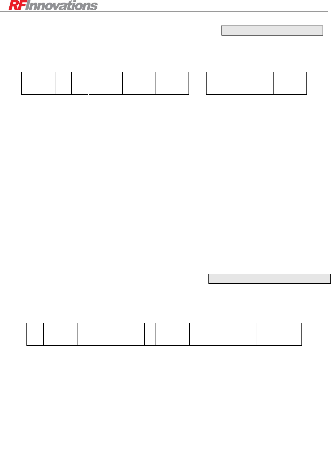
Protocol Operation
Crescendo UHF Half-Duplex User Manual Page 40 of 78
6.7 Distributed Network Protocol (DNP)
The Crescendo supports the Distributed Network Protocol (DNP) as defined by the DNP Users Group
(http://www.dnp.org/). The packet structure for a DNP packet expected on the serial port is shown below.
…
Start
0x0564
Destination
(16)
Source
(16)
CRC
(16)
Data
(0…16)
Len
(8)
Ctrl
(8)
CRC
(16)
Figure 9: DNP packet format
Start (16-bit): A fixed start of packet marker, always 0x0564.
Len (8-bit): The length of the packet, including all fields except Start, Length, and CRC.
Ctrl (8-bit): Defines the control information for the packet.
Destination (16-bit): The 16-bit destination address. This can be any singlecast address, or the
broadcast address.
Source (16-bit): The 16-bit source address. When sending a packet to a radio, this field does not
need to be set.
Data: The fixed length header block is followed by optional data blocks of up to 16 bytes.
CRC (16-bit): A 16-bit CRC value calculated over the previous fields, excluding the CRC fields.
The CRC uses the polynomial 0xA6BC.
6.8 Datagram Protocol
When using the datagram protocol, packets are passed to the Crescendo to be transmitted over the air. The
packet format is given in Figure 10.
Start
0xC1
Destination
(16)
Source
(16)
DP
(2)
CRC
(32)
Data
(1…Slot Size)
SP
(2)
Res.
(4)
Length
(16)
Figure 10: Datagram protocol packet format
Note that the number of data bytes in a datagram packet must be no more than max packet size. The fields of
a datagram packet are:
Start (8-bit): A fixed start of packet marker, always 0xC1.
Length (16-bit): The length of the packet, including all fields except Start, Length, and CRC.
Destination (16-bit): The 16-bit destination address. This can be any singlecast address, or the
broadcast address. The destination cannot be the same as the radios source address.
Source (16-bit): The 16-bit source address. When sending a packet to a radio, this field does not
need to be set. The source will automatically be set to the radio’s local address.
Main -> Protocol -> DNP
Main -> Protocol -> Datagram

Protocol Operation
Crescendo UHF Half-Duplex User Manual Page 41 of 78
DP (2-bit): The destination serial port. This can be either 00 for the main port or 01 for the
auxiliary port.
SP (2-bit): The source serial port. When sending a packet to a radio, this field does not need to be
set. The value will automatically be set to the serial port the packet was inserted on.
Res (4-bit): Reserved for future use. This field should be set to all zeros.
Data: The data to be transmitted. The amount of data in each datagram must be equal to or less
than the slot size.
CRC (32-bit): A 32-bit CRC value calculated over the entire packet, excluding the Start and CRC
fields.
There are two options for the CRC field.
1. Fixed: The value is fixed to 0xEDB88320.
2. CRC: The CRC value is calculated using a 32-bit CRC with
Initial Value: 0xFFFFFFFF
Polynomial: 0xEDB88320
Final XOR: 0xFFFFFFFF
When a radio modem receives a datagram packet over the air, the data will be output by the datagram
protocol in the same packet format as described in Figure 10.
An example Datagram packet with a calculated CRC-32 is shown in Figure 11.
Start
0xC1
Destination
0x0001
Source
0x0000
CRC
0x9496D61C
Data
0x54 0x45 0x53 0x54
DP / SP / Res
0x00
Length
0x0009
Figure 11: Example datagram protocol packet
Datagram protocol applications are given in section 7.4.
6.9 RF Link Status
The Crescendo provides an RF link status indication for each serial port. The RF link status depends on the
protocol mode being used and the current state of that protocol. The meaning of different RF link status
values is provided in Table 17 for each protocol mode.
Protocol
State
RF Link Status
Point-to-point
Connection Based
Connected if a path exists between the
local and remote device. Not Connected
if there is no communications path.
Connectionless
N/A
Point-to-multipoint
N/A
Main -> Protocol

Protocol Operation
Crescendo UHF Half-Duplex User Manual Page 42 of 78
Hayes dial-up
Connection
established
Connected if a path exists between the
local and remote device. Not Connected
if there is no communications path.
No connection
established
Not Connected
Datagram
N/A
Table 17: RF link status for different protocol modes
Whenever the protocol mode on a serial port is temporarily disabled (such as when the menu is enabled on
the port, or when the Cruise Control application has been started), the RF Link Status will be displayed as
N/A.
6.10 Protocol to Radio Address Mapping
Protocol address mapping can be used in situations where the radio address is not the same as the protocol
address, or where there is more than one protocol address for each radio address. A protocol mapping entry
has each of the following fields:
First Addr: The first protocol address to apply to the protocol mapping.
Last Addr: The last protocol address to apply to the protocol mapping.
Radio Addr: The radio address to apply to the protocol mapping.
Type: A protocol mapping entry can be one of four types:
o Unused: The protocol mapping entry is not used.
o Single: For a single entry, the packet is sent to the associated radio address if the protocol
address matches the first address. The last address is ignored. This is a “one-to-one” mapping.
o Mapped: For a mapped entry, the mapping is applied if the protocol address is within the range
specified by the first and last addresses. To determine the radio address, the offset from the first
address is added to the associated radio address entry. This is a series of “one-to-one” mappings.
o Grouped: For a grouped entry, the packet is sent to the associated radio address if the protocol
address is within the range of the first and last address. This is a “many-to-one” mapping.
An example protocol mapping table is shown in Figure 12.
Main -> Protocol

Protocol Operation
Crescendo UHF Half-Duplex User Manual Page 43 of 78
*** Protocol Mapping Menu ***
|Type |First Addr |Last Addr |Radio Addr |
|-------------------|-------------------|-------------------|-------------------|
(0) |Single | 1| 0| 1001|
(1) |Unused | 2| 0| 1002|
(2) |Single | 3| 0| 1003|
(3) |Mapped | 4| 10| 1004|
(4) |Grouped | 11| 20| 1011|
(5) |Unused | 0| 0| 0|
(6) |Unused | 0| 0| 0|
(7) |Unused | 0| 0| 0|
(8) |Unused | 0| 0| 0|
(9) |Unused | 0| 0| 0|
(A) |Unused | 0| 0| 0|
(B) |Unused | 0| 0| 0|
(C) |Unused | 0| 0| 0|
(D) |Unused | 0| 0| 0|
(E) |Unused | 0| 0| 0|
(F) |Unused | 0| 0| 0|
(ESC) - Previous Menu
Enter Selection:
Figure 12: Example protocol mapping table
For the example in Figure 12 the following mapping would occur:
1. A protocol packet with an address of 1 would be sent to radio address 1001.
2. A protocol packet with an address of 4 would be sent to radio address 1004.
3. A protocol packet with an address of 9 would be sent to radio address 1009.
4. A protocol packet with an address of 10 would be sent to radio address 1010.
5. A protocol packet with an address of 11 would be sent to radio address 1011.
6. A protocol packet with an address of 15 would be sent to radio address 1011.
7. A protocol packet of address 2 does not have a matching entry, note entry (1) is unused, so would be
sent to radio address 2.
8. Any protocol packet with an address that does not have a matching entry will be sent to a radio
address that matches the protocol address.
Note that only DNP and Modbus RTU protocol utilise the protocol mapping table and that the mapping is
only applied to packets arriving over the serial port.
6.11 Multiple Protocol Modes
The Crescendo is a dual serial port radio modem, and both ports can be independently configured with
different protocol modes. Using both ports for data may result in increased latency, owing to greater
bandwidth requirements and increased probability of collision.
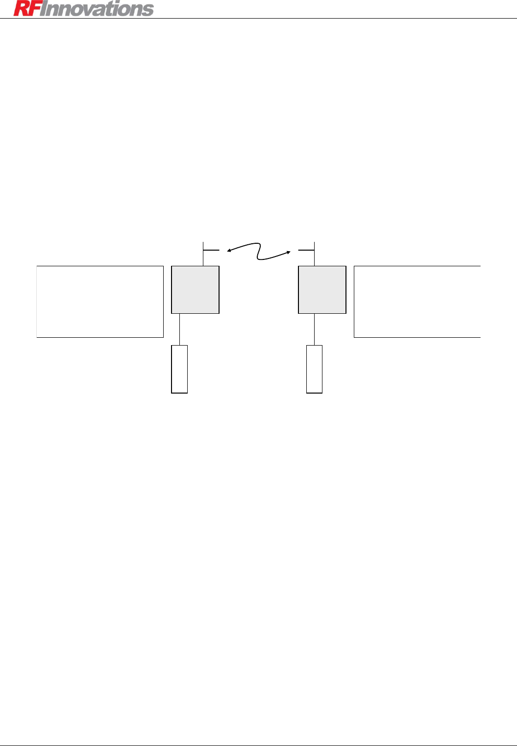
Applications
Crescendo UHF Half-Duplex User Manual Page 44 of 78
7. Applications
This section presents typical Crescendo usage scenarios. The aim of these scenarios is to illustrate radio
configuration.
7.1 Point-to-point Networks
7.1.1 Basic Point-to-point Network
A basic point-to-point network consists of two units configured such that the point-to-point destination of
one unit is the address of the other. This scenario is shown in Figure 13.
Crescendo
1000
Crescendo
1001
Main
DTE
Main
DTE
RADIO CONFIGURATION
Rx Address: 1001
PROTOCOL CONFIGURATION
Main Port: Point-to-point to 1000
SERIAL CONFIGURATION
Main Port: 115200, 8N1, Hardware Flow
RADIO CONFIGURATION
Address: 1000
PROTOCOL CONFIGURATION
Main: Point-to-point to 1001
SERIAL CONFIGURATION
Main Port: 115200, 8N1, Hardware Flow
Figure 13: Basic point-to-point network
In this network, data presented on the main port of the unit 1000 will be output on the main port of unit
1001, and vice versa.
Other configuration parameters which may help in fine tuning the system operation are:
Rx packetiser timers. See page 18 for more information.
Point-to-point connection mode. See page 35 for more information.
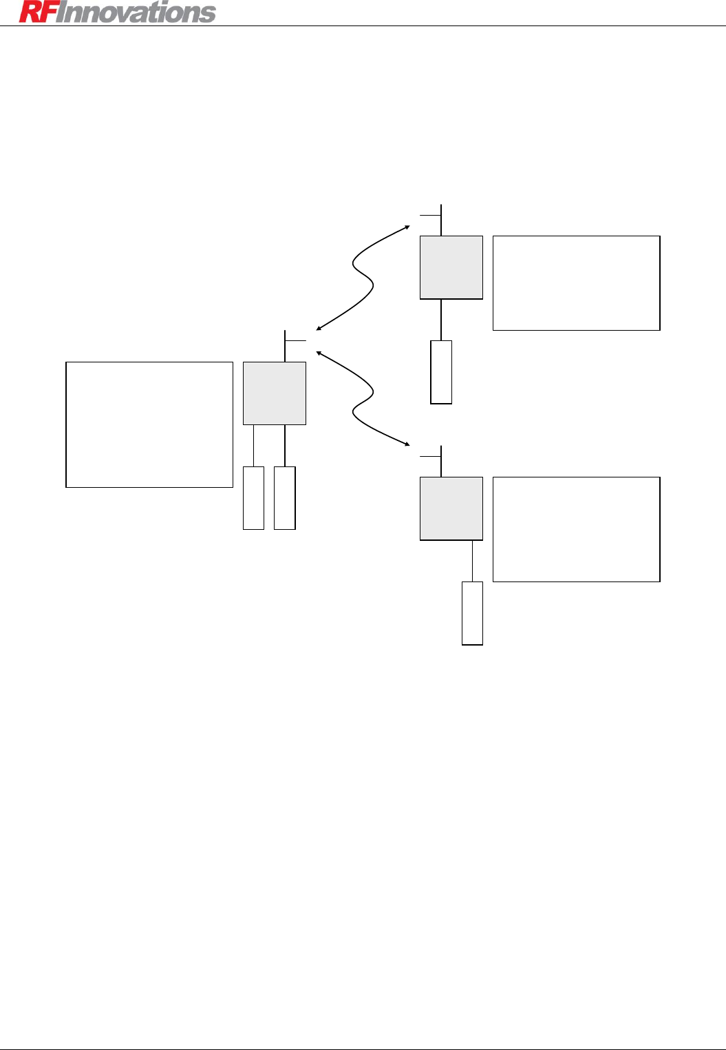
Applications
Crescendo UHF Half-Duplex User Manual Page 45 of 78
7.1.2 Multiple Port Point-to-point Network
Two point-to-point destinations can be used by configuring the point-to-point protocol on both serial ports of
base unit, and then having two remotes each connected to a different port. This scenario is shown in Figure
15.
Crescendo
Base
1000
Crescendo
Remote
1001
Main
DTE
RADIO CONFIGURATION
Address: 1000
PROTOCOL CONFIGURATION
Main: Point-to-point to 1001
Aux: Point-to-point to 1002
Aux: Start in local disabled
SERIAL CONFIGURATION
Main Port: 19200, 8N1, Hardware Flow
Aux Port: 19200, 8N1
DTE
RADIO CONFIGURATION
Address: 1001
PROTOCOL CONFIGURATION
Main: Point-to-point to 1000
SERIAL CONFIGURATION
Main Port: 19200, 8N1, Hardware Flow
Main
Crescendo
Remote
1002
DTE
Aux
DTE
Aux
RADIO CONFIGURATION
Address: 1002
PROTOCOL CONFIGURATION
Aux: Point-to-point to 1000
Aux: Start in local disabled
SERIAL CONFIGURATION
Aux Port: 19200, 8N1
Figure 14: Multiple port point-to-point network
Note that the main port on the base is connected to the main port on radio 1001, while the auxiliary port on
the base is connected to the auxiliary port on remote 1002.
Other configuration parameters which may help in fine tuning the system operation are:
Rx packetiser timers. See page 18 for more information.
Max packet size. See section 5.3.5 for more information.
Singlecast retries. See page 25 for more information.
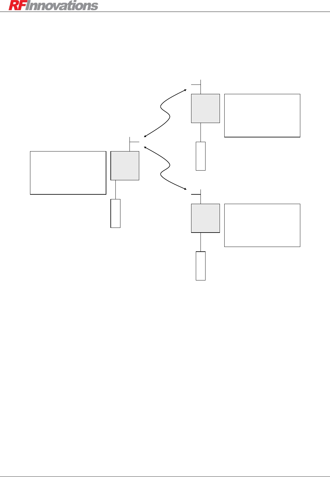
Applications
Crescendo UHF Half-Duplex User Manual Page 46 of 78
7.1.3 Multiple Destination Point-to-point Network
Multiple destinations can be used by configuring any number of remote units and then changing the
destination address of the base unit using local command mode. This scenario is shown in Figure 15.
Crescendo
Base
1000
Crescendo
Remote
1001
Main
DTE
RADIO CONFIGURATION
Address: 1000
PROTOCOL CONFIGURATION
Main Port: Point-to-point to 1001 or 1002
SERIAL CONFIGURATION
Main Port: 19200, 8N1, Hardware Flow
DTE
RADIO CONFIGURATION
Address: 1001
PROTOCOL CONFIGURATION
Main Port: Point-to-point to 1000
SERIAL CONFIGURATION
Main Port: 19200, 8N1, Hardware Flow
Main
Crescendo
Remote
1002
RADIO CONFIGURATION
Address: 1002
PROTOCOL CONFIGURATION
Main Port: Point-to-point to 1000
SERIAL CONFIGURATION
Main Port: 19200, 8N1, Hardware Flow
DTE
Main
Figure 15: Multiple destination point-to-point network
The point-to-point destination address on the main port of the base unit determines which remote unit the
base is connected to. To change the point-to-point destination address on main port, the follow these steps:
Enable the local command mode on the main port by transmitting the escape sequence (see section
6.5.3 on page 37).
Use the AT command to change the main port point-to-point destination (ATS52=1001).
Return the port to online state using the online command (ATO).
Other configuration parameters which may help in fine tuning the system operation are:
Rx packetiser timers. See page 18 for more information.
Max packet size. See section 5.3.5 for more information.
Singlecast retries. See page 25 for more information.
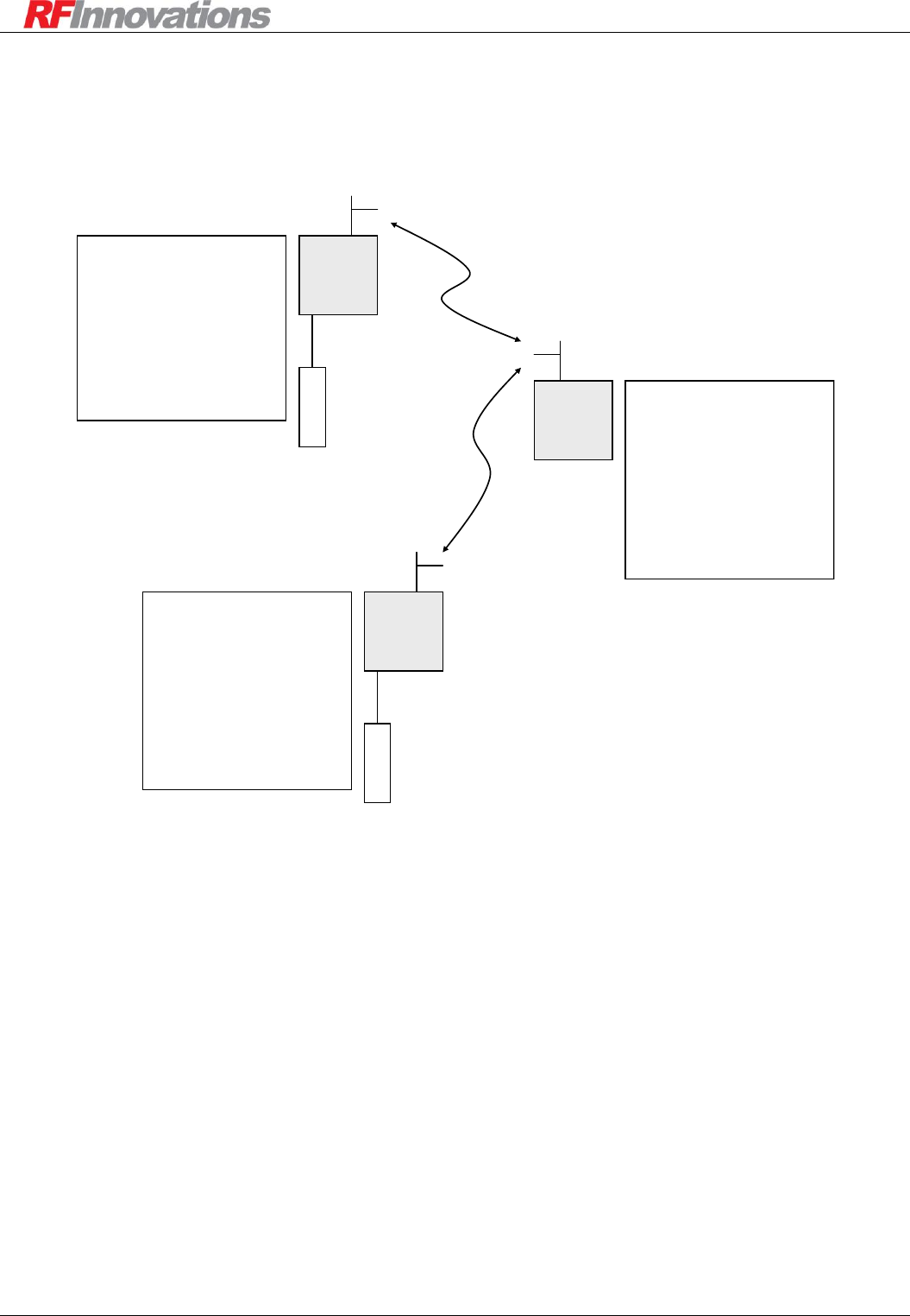
Applications
Crescendo UHF Half-Duplex User Manual Page 47 of 78
7.1.4 Point-to-point Network with Repeater
Repeaters can be used to extend the range of a point-to-point network, as shown in Figure 20.
Crescendo
Base
1000
Crescendo
Repeater
2000
Main
DTE
RADIO CONFIGURATION
Rx Address: 2000
Store and Forward Repeater: True
Repeaters in Network: 1
PROTOCOL CONFIGURATION
Main Port: Hayes Dial-up
SERIAL CONFIGURATION
Main Port: 38400, 8N1, Hardware Flow
RADIO CONFIGURATION
Rx Address: 1000
Repeaters in Network: 1
ROUTING TABLE
Route 2000-2999 to 2000
PROTOCOL CONFIGURATION
Main Port: Point-to-point to 2001
SERIAL CONFIGURATION
Main Port: 38400, 8N1, Hardware Flow
Crescendo
Remote
2001
DTE
Main
RADIO CONFIGURATION
Rx Address: 2001
Repeaters in Network: 1
ROUTING TABLE
Route 1000-1999 to 2000
PROTOCOL CONFIGURATION
Main Port: Point-to-point to 1000
SERIAL CONFIGURATION
Main Port: 38400, 8N1, Hardware Flow
Figure 16: Point-to-point network with repeater
The following should be noted for the point-to-point network with repeaters:
All units in the network have ‘Repeaters in network’ set to 1.
The main port protocol on the repeater is set to Hayes even though the main port is not used. This is
so the unit is in packet driven mode rather than data driven mode (see section 5).
Routing tables need to be set on the base and remote radio modems.
Other configuration parameters which may help in fine tuning the system operation are:
Rx packetiser timers. See page 18 for more information.
Max packet size. See section 5.3.5 for more information.
Singlecast retries. See page 25 for more information.
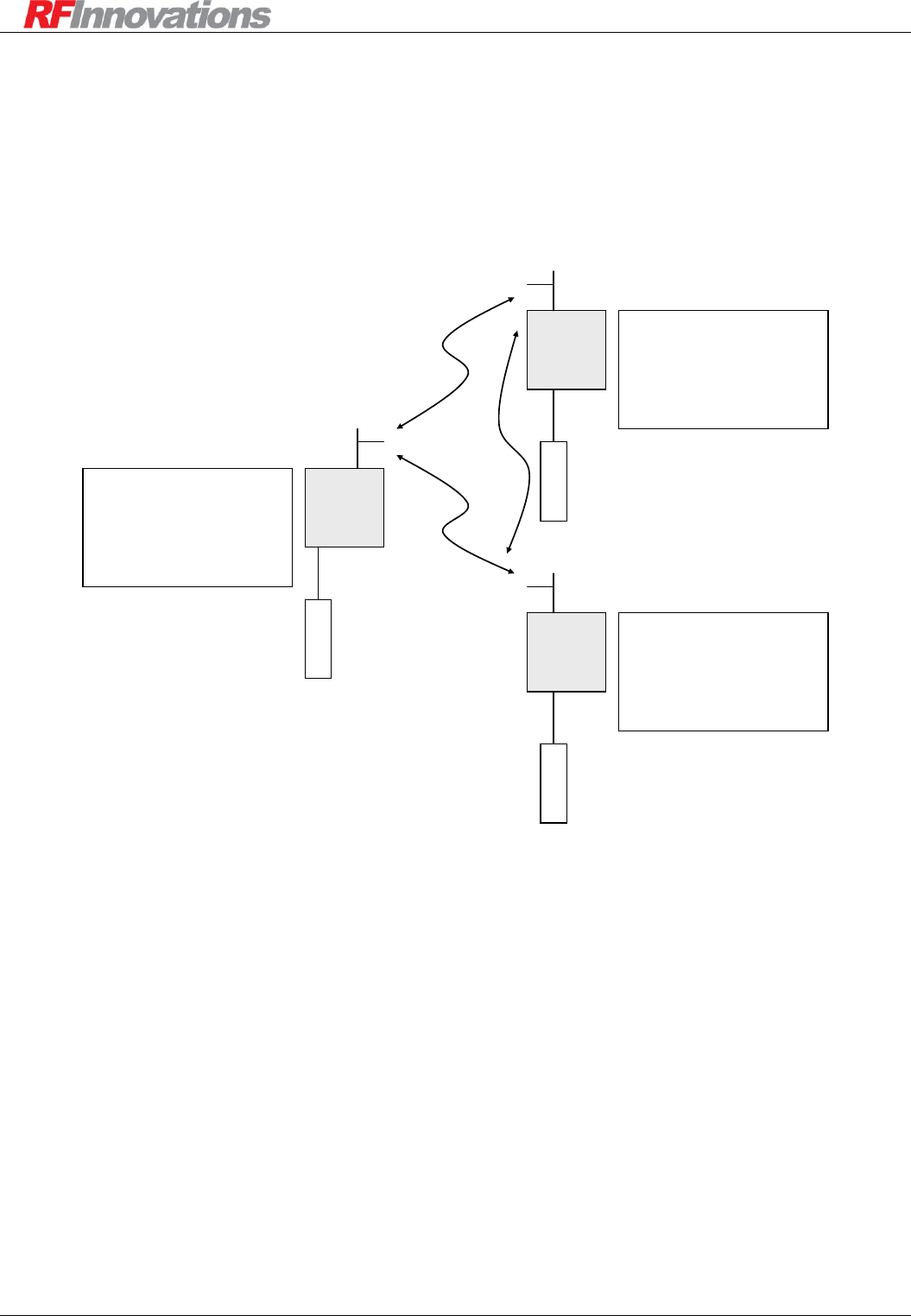
Applications
Crescendo UHF Half-Duplex User Manual Page 48 of 78
7.2 Point-to-multipoint Networks
7.2.1 Basic Point-to-multipoint Network
A basic point-to-multipoint network is shown in Figure 17.
Crescendo
Base
1000
Crescendo
Remote
1001
Main
DTE
RADIO CONFIGURATION
Address: 1000
PROTOCOL CONFIGURATION
Main Port: Point-to-multipoint
SERIAL CONFIGURATION
Main Port: 19200, 8N1, Hardware Flow
DTE
RADIO CONFIGURATION
Address: 1001
PROTOCOL CONFIGURATION
Main Port: Point-to-multipoint
SERIAL CONFIGURATION
Main Port: 19200, 8N1, Hardware Flow
Main
Crescendo
Remote
1002
RADIO CONFIGURATION
Address: 1002
PROTOCOL CONFIGURATION
Main Port: Point-to-multipoint
SERIAL CONFIGURATION
Main Port: 19200, 8N1, Hardware Flow
DTE
Main
Figure 17: Basic point-to-multipoint network
In this network, data passed to the main port on any unit will be output on the main port of both other units.
Other configuration parameters which may help in fine tuning the system operation are:
Rx packetiser timers. See page 18 for more information.
Max packet size. See section 5.3.5 for more information.
Broadcast retransmissions. See page 25 for more information.
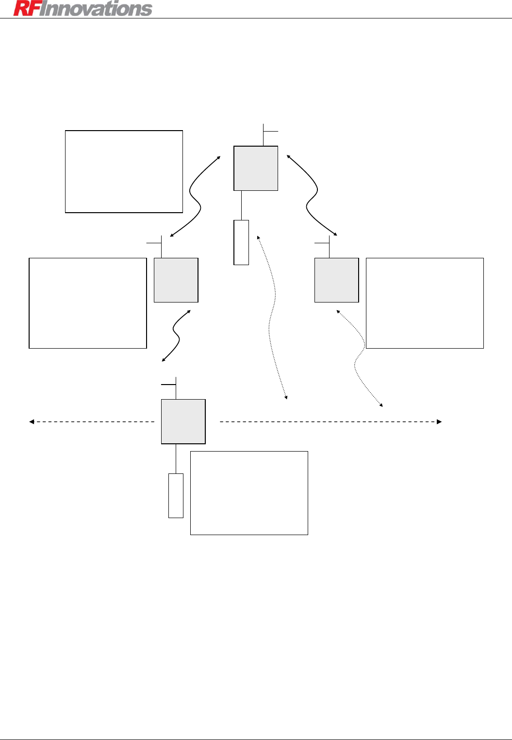
Applications
Crescendo UHF Half-Duplex User Manual Page 49 of 78
7.2.2 Point-to-multipoint Network with Roaming Remote
In some applications the remote unit may be mobile, and needs to ‘roam’ between areas of coverage. A
point-to-multipoint network configured for this purpose is shown in Figure 18.
Crescendo
Base
1000
Crescendo
Repeater
1002
Main
RTU
RADIO CONFIGURATION
Rx Address: 1002
Broadcast Retransmissions: 4
Store and Forward Repeater: True
Repeaters in Network: 1
PROTOCOL CONFIGURATION
Main Port: Point-to-multipoint
SERIAL CONFIGURATION
Main Port: 19200, 8N1, 2ms RX Timer
Crescendo
Repeater
1001
RADIO CONFIGURATION
Rx Address: 1001
Broadcast Retransmissions: 4
Store and Forward Repeater: True
Repeaters in Network: 1
PROTOCOL CONFIGURATION
Main Port: Point-to-multipoint
SERIAL CONFIGURATION
Main Port: 19200, 8N1, 2ms RX Timer
Crescendo
Remote
2000
RTU
RADIO CONFIGURATION
Rx Address: 2000
Broadcast Retransmissions: 4
Repeaters in Network: 1
PROTOCOL CONFIGURATION
Main Port: Point-to-multipoint
SERIAL CONFIGURATION
Main Port: 19200, 8N1, 2ms RX Timer
Main
RADIO CONFIGURATION
Rx Address: 1000
Broadcast Retransmissions: 4
Repeaters in Network: 1
PROTOCOL CONFIGURATION
Main Port: Point-to-multipoint
SERIAL CONFIGURATION
Main Port: 19200, 8N1, 2ms RX Timer
Figure 18: Point-to-multipoint network with roaming remote
As with other types of broadcast network, setting the max packet size will help fine tune the network. Note
that while there are two store-and-forward repeaters in the network, the repeaters in network setting is set to
one. Repeaters in network specifies the maximum number of repeaters a packet must go through to reach a
destination.
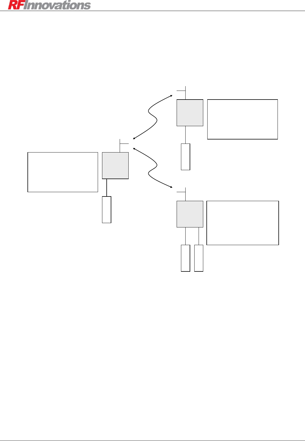
Applications
Crescendo UHF Half-Duplex User Manual Page 50 of 78
7.3 Hayes Dial-up Networks
7.3.1 Basic Hayes Dial-up Network
A basic Hayes dial-up network is given in Figure 19.
Crescendo
Base
1000
Crescendo
Remote
1001
Main
DTE
RADIO CONFIGURATION
Rx Address: 1000
PROTOCOL CONFIGURATION
Main Port: Hayes Dial-up
SERIAL CONFIGURATION
Main Port: 115200, 8N1
DTE
RADIO CONFIGURATION
Rx Address: 1001
PROTOCOL CONFIGURATION
Main Port: Hayes Dial-up
SERIAL CONFIGURATION
Main Port: 115200, 8N1
Main
Crescendo
Remote
1002
RADIO CONFIGURATION
Rx Address: 1002
PROTOCOL CONFIGURATION
Main Port: Hayes Dial-up
Auxiliary Port: Start in local mode disabled
SERIAL CONFIGURATION
Main Port: 115200, 8N1
Aux Port: 115200, 8N1
DTE
Main
DTE
Aux
Figure 19: Basic Hayes dial-up network
In order to establish a connection from the base to the main port on remote 1001, the following dial string is
used:
ATD100100<CR>
To establish a connection to the auxiliary port of remote 1002, the following dial string is used:
ATD100201<CR>
Information on hanging up a Hayes dial-up connection can be found in section 6.5.4 on page 37.
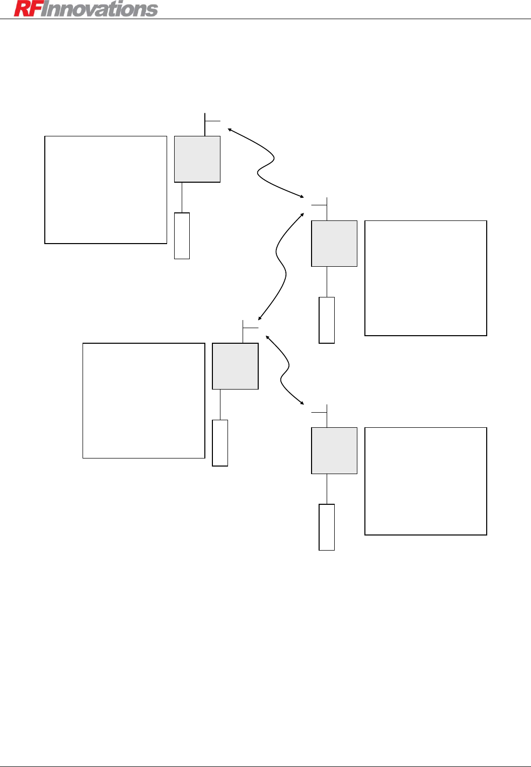
Applications
Crescendo UHF Half-Duplex User Manual Page 51 of 78
7.3.2 Hayes Dial-up Network with Repeaters
Repeaters can be used to extend the range of a Hayes dial-up network, as shown in Figure 20.
Crescendo
Base
1000
Crescendo
Repeater
2000
Main
DTE
RADIO CONFIGURATION
Rx Address: 2000
Store and Forward Repeater: True
Repeaters in Network: 2
ROUTING TABLE
Route 3000-3999 to 3000
PROTOCOL CONFIGURATION
Main Port: Hayes Dial-up
SERIAL CONFIGURATION
Main Port: 38400, 8N1, Hardware Flow
RADIO CONFIGURATION
Rx Address: 1000
Repeaters in Network: 2
ROUTING TABLE
Route 2000-3999 to 2000
PROTOCOL CONFIGURATION
Main Port: Hayes Dial-up
SERIAL CONFIGURATION
Main Port: 38400, 8N1, Hardware Flow
Crescendo
Repeater
3000
DTE
RADIO CONFIGURATION
Rx Address: 3001
Repeaters in Network: 2
ROUTING TABLE
Route 1000-3999 to 3000
PROTOCOL CONFIGURATION
Main Port: Hayes Dial-up
SERIAL CONFIGURATION
Main Port: 38400, 8N1, Hardware Flow
Main
DTE
Main
Crescendo
Remote
3001
RADIO CONFIGURATION
Rx Address: 3000
Store and Forward Repeater: True
Repeaters in Network: 2
ROUTING TABLE
Route 1000-2999 to 2000
PROTOCOL CONFIGURATION
Main Port: Hayes Dial-up
SERIAL CONFIGURATION
Main Port: 38400, 8N1, Hardware Flow
DTE
Main
Figure 20: Hayes dial-up network with repeaters
The following dial string is used to dial the second main port on the second store-and-forward repeater:
ATD300000<CR>
To dial the main port on the remote, the following dial string is used:
ATD300100<CR>
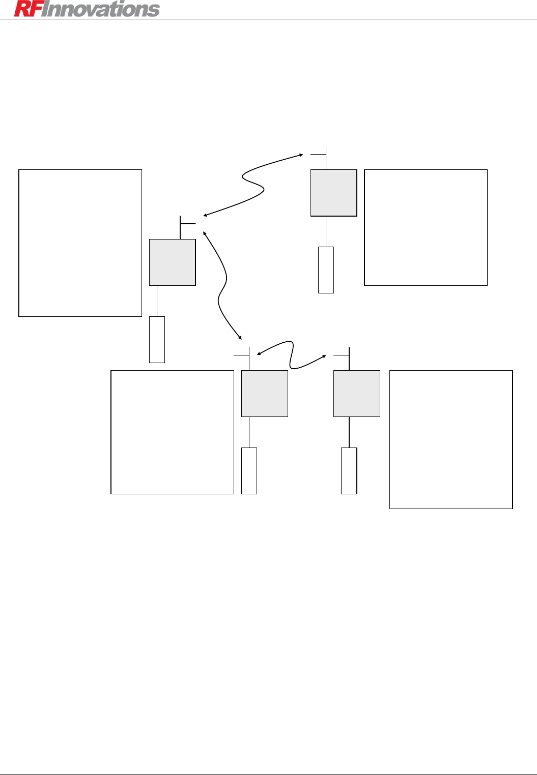
Applications
Crescendo UHF Half-Duplex User Manual Page 52 of 78
7.4 Modbus/DNP Networks
7.4.1 Basic Modbus RTU Network with Repeater
A Modbus network with repeater is shown in Figure 21.
Crescendo
Base
1000
Crescendo
Remote
1001
Main
RTU BASE
RTU 2
RADIO CONFIGURATION
Rx Address: 1001
Repeaters in Network: 1
Max Packet Size: 267
PROTOCOL CONFIGURATION
Main Port: Modbus RTU
PROTOCOL MAPPING
Grouped 1-247 to 1000
SERIAL CONFIGURATION
Main Port: 19200, 8N1, 2ms RX Timer
Main
Crescendo
Repeater
2000
RADIO CONFIGURATION
Rx Address: 2000
Store and Forward Repeater: True
Repeaters in Network: 1
Max Packet Size: 267
PROTOCOL CONFIGURATION
Main Port: Modbus RTU
PROTOCOL MAPPING
Grouped 1-247 to 1000
SERIAL CONFIGURATION
Main Port: 19200, 8N1, 2ms RX Timer
RTU 3
Main
Crescendo
Remote
2001
RTU 4
RADIO CONFIGURATION
Rx Address: 2001
Repeaters in Network: 1
Max Packet Size: 267
PROTOCOL CONFIGURATION
Main Port: Modbus RTU
ROUTING TABLE
Route 1000-1099 to 2000
PROTOCOL MAPPING
Grouped 1-247 to 1000
SERIAL CONFIGURATION
Main Port: 19200, 8N1, 2ms RX Timer
Main
RADIO CONFIGURATION
Rx Address: 1000
Repeaters in Network: 1
Max Packet Size: 267
PROTOCOL CONFIGURATION
Main Port: Modbus RTU
ROUTING TABLE
Route 2000-2099 to 2000
PROTOCOL MAPPING
Single 2 to 1001
Mapped 3-4 to 2000
SERIAL CONFIGURATION
Main Port: 19200, 8N1, 2ms RX Timer
Figure 21: Modbus network with repeater
In order to support the ModBus protocol, an RX packetiser timer of 2 ms has been used on the main port of
each unit (see section 4.3.2 on page 18 for more information on packetiser timers).
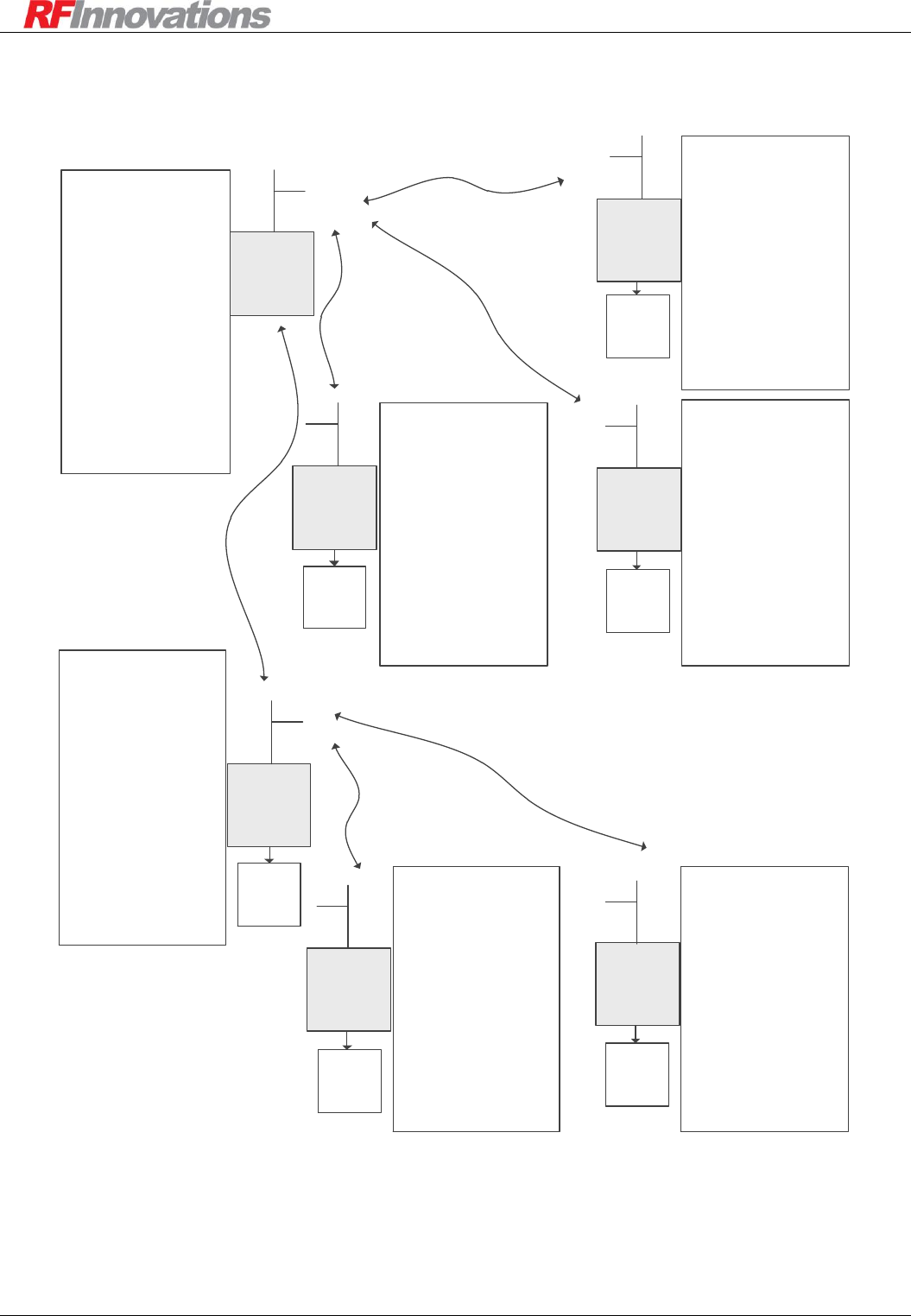
Applications
Crescendo UHF Half-Duplex User Manual Page 53 of 78
7.4.2 Modbus with Modbus Query Enabled
Crescendo
Remote
22
Crescendo
Remote
21
Crescendo
Repeater
20
Crescendo
Remote
13
Crescendo
Remote
12
Crescendo
Remote
11
Crescendo
Base
10
RADIO CONFIGURATION
Radio Address: 22
Repeaters in Network: 1
Max packet Size: 268 Bytes
Routing Table:
10,29,20
Main Baud Rate: 9600
Main Parity: Odd
Rx Packetiser Timer: 4 ms
PROTOCOL
CONFIGURATION
Modbus Query: Enabled
Modbus Address: 22
Protocol Mapping:
Grouped,1,247,10
Main Port Mode: Modbus RTU
RADIO CONFIGURATION
Radio Address: 21
Repeaters in Network: 1
Max Packet Size: 268 Bytes
Routing Table:
10,29,20
Main Baud Rate: 9600
Main Parity: Odd
Rx Packetiser Timer: 4 ms
PROTOCOL
CONFIGURATION
Modbus Query: Enabled
Modbus Address: 21
Protocol Mapping:
Grouped,1,247,10
Main Port Mode: Modbus RTU
RADIO CONFIGURATION
Radio Address: 20
Repeater Mode: Store and
Forward
Repeaters in Network: 1
Max Packet Size: 268 Bytes
Routing Table:
10,19,10
Main Baud Rate: 9600
Main Parity: Odd
Rx Packetiser Timer: 4 ms
PROTOCOL
CONFIGURATION
Modbus Query: Enabled
Modbus Address: 20
Protocol Mapping:
Grouped,1,247,10
Main Port Mode: Modbus RTU
RADIO CONFIGURATION
Radio Address: 13
Repeaters in Network: 1
Max Packet Size: 268 Bytes
Routing Table:
10,29,10
Main Baud Rate: 9600
Main Parity: Odd
Rx Packetiser Timer: 4 ms
PROTOCOL
CONFIGURATION
Modbus Query: Enabled
Modbus Address: 13
Protocol Mapping:
Grouped,1,247,10
Main Port Mode: Modbus RTU
RADIO CONFIGURATION
Radio Address: 12
Repeaters in Network: 1
Max Packet Size: 268 Bytes
Routing Table:
10,29,10
Main Baud Rate: 9600
Main Parity: Odd
Rx Packetiser Timer: 4 ms
PROTOCOL
CONFIGURATION
Modbus Query: Enabled
Modbus Address: 12
Protocol Mapping:
Grouped,1,247,10
Main Port Mode: Modbus RTU
RADIO CONFIGURATION
Radio Address: 11
Repeaters in Network: 1
Max Packet Size: 268 Bytes
Routing Table:
10,29,10
Main Baud Rate: 9600
Parity: Odd
Rx Packetiser Timer: 4 ms
PROTOCOL
CONFIGURATION
Modbus Query: Enabled
Modbus Address: 11
Protocol Mapping:
Grouped,1,247,10
Main Port Mode: Modbus RTU
RADIO CONFIGURATION
Radio Address: 10
Repeater Mode: Store and
Forward
Repeaters in Network: 1
Max Packet Size: 268 Bytes
Routing Table:
20,29,20
Main Baud Rate: 9600
Main Parity: Odd
Rx Packetiser Timer: 4 ms
PROTOCOL
CONFIGURATION
Modbus Query: Enabled
Modbus Address: 10
Protocol Mapping:
Mapped 100,129,10
Main Port Mode: Modbus RTU
PLC 113 PLC 112
PLC 111
PLC 120
PLC 122 PLC 121
Figure 22: Modbus with Modbus query enabled
See page 39 for more information on Modbus query support.
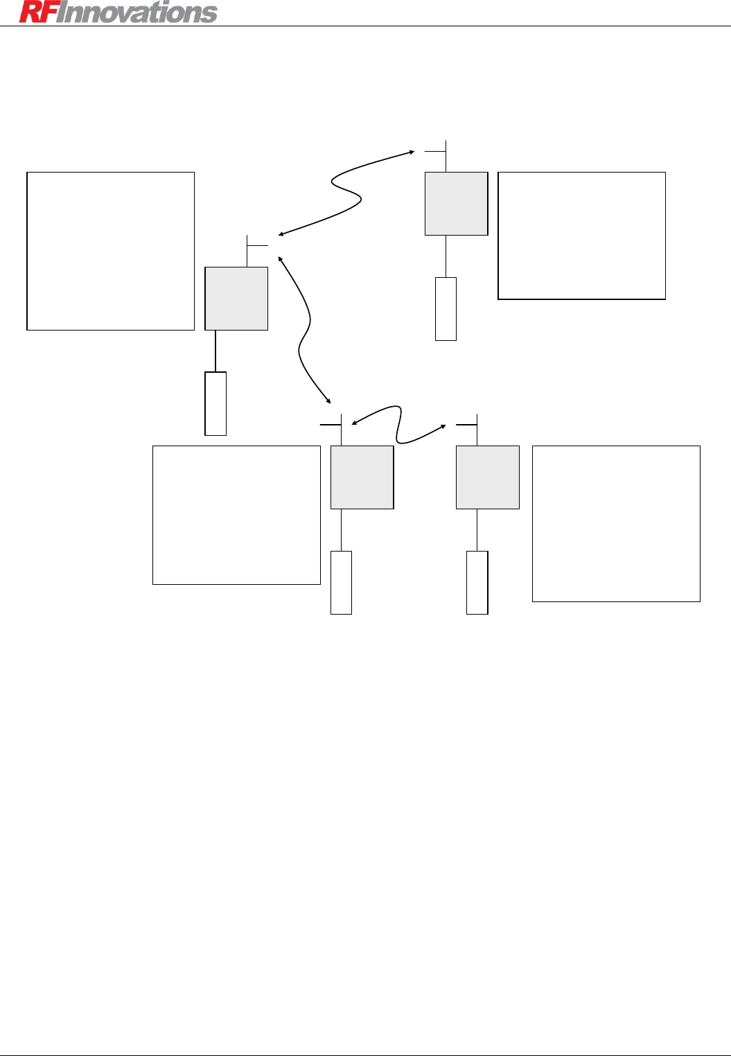
Applications
Crescendo UHF Half-Duplex User Manual Page 54 of 78
7.4.3 DNP Network with Repeater
A DNP network with repeater is shown in Figure 23.
Crescendo
Base
1000
Crescendo
Remote
1001
Main
RTU BASE
RTU 2
RADIO CONFIGURATION
Rx Address: 1001
Repeaters in Network: 1
Max Packet Size: 304
PROTOCOL CONFIGURATION
Main Port: DNP
SERIAL CONFIGURATION
Main Port: 19200, 8N1, 2ms RX Timer
Main
Crescendo
Repeater
2000
RADIO CONFIGURATION
Rx Address: 2000
Repeater Mode: Store and Forward
Repeaters in Network: 1
Max Packet Size: 304
PROTOCOL CONFIGURATION
Main Port: DNP
SERIAL CONFIGURATION
Main Port: 19200, 8N1, 2ms RX Timer
RTU 3
Main
Crescendo
Remote
2001
RTU 4
RADIO CONFIGURATION
Rx Address: 2001
Repeaters in Network: 1
Max Packet Size: 304
PROTOCOL CONFIGURATION
Main Port: DNP
ROUTING TABLE
Route 1000-1099 to 2000
SERIAL CONFIGURATION
Main Port: 19200, 8N1, 2ms RX Timer
Main
RADIO CONFIGURATION
Rx Address: 1000
Repeaters in Network: 1
Max Packet Size: 304
PROTOCOL CONFIGURATION
Main Port: DNP
ROUTING TABLE
Route 2000-2099 to 2000
SERIAL CONFIGURATION
Main Port: 19200, 8N1, 2ms RX Timer
Figure 23: DNP network with repeater
Note that no protocol mapping has been utilised. It is therefore assumed that the mapping from protocol
address to radio address is one-to-one, and the protocol address is the same as the radio address.
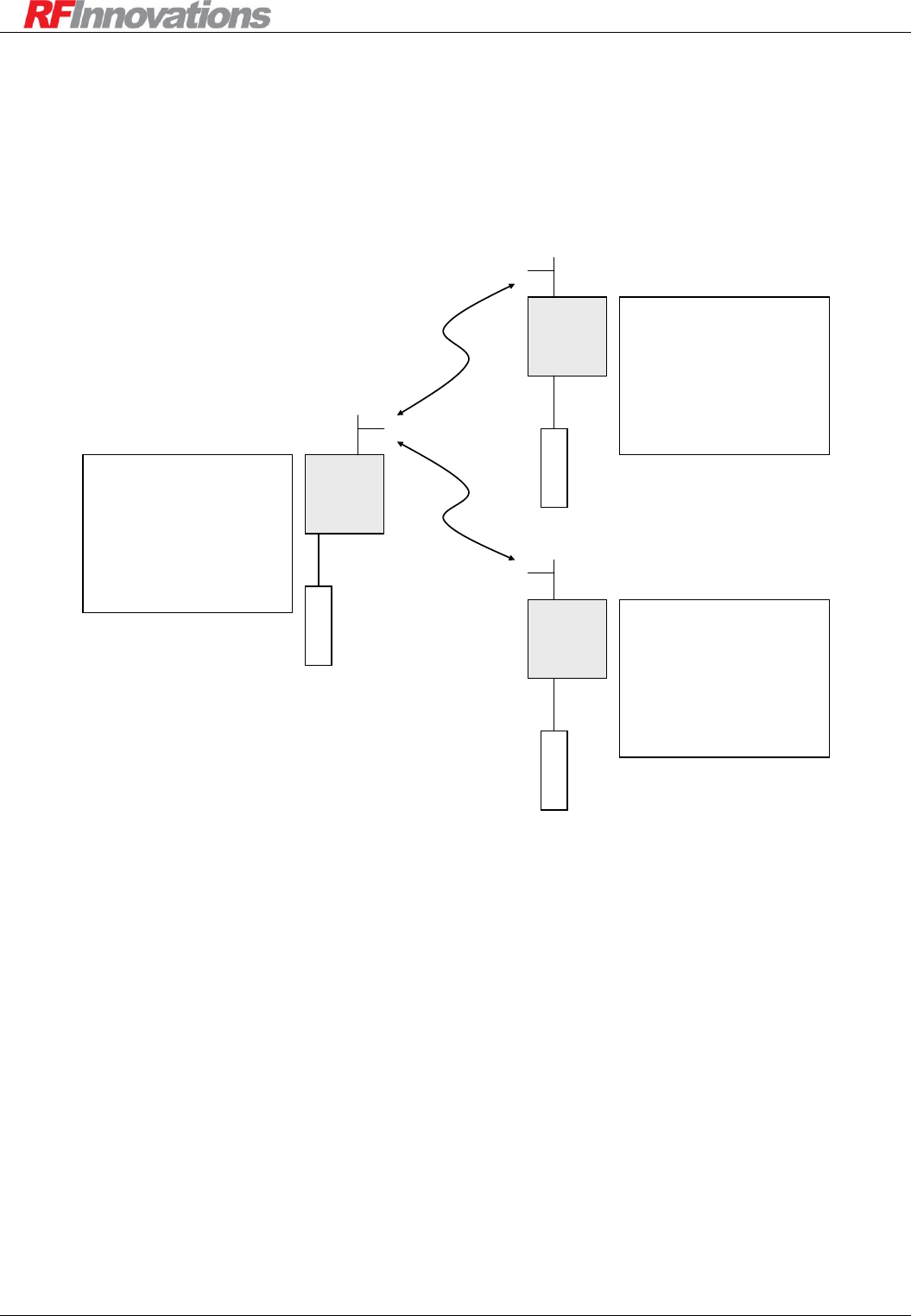
Applications
Crescendo UHF Half-Duplex User Manual Page 55 of 78
7.5 Datagram Networks
7.5.1 Basic Datagram Network
A basic datagram network is shown in Figure 24.
Crescendo
Base
1000
Crescendo
Remote 1
1001
Main
DTE
RADIO CONFIGURATION
Rx Address: 1000
PROTOCOL CONFIGURATION
Main Port: Datagram
SERIAL CONFIGURATION
Main Port: 38400, 8N1, Hardware Flow
DTE
RADIO CONFIGURATION
Rx Address: 1001
PROTOCOL CONFIGURATION
Main Port: Datagram
SERIAL CONFIGURATION
Main Port: 38400, 8N1, Hardware Flow
Main
Crescendo
Remote 2
1002
DTE
Main
RADIO CONFIGURATION
Rx Address: 1002
PROTOCOL CONFIGURATION
Main Port: Datagram
SERIAL CONFIGURATION
Main Port: 38400, 8N1, Hardware Flow
Figure 24: Basic datagram network
In this network, datagrams presented to the main port of the base with the destination address set to 1001
will be routed to remote 1, while those with destination address 1002 will be routed to remote 2.

Appendix A Technical Specifications
Crescendo UHF Half-Duplex User Manual Page 56 of 78
Appendix A Technical Specifications
A.1 Type Approvals
Australia/ New Zealand
AS 4295 -1995
Australian Supplier ID: N161
FCC
CFR 47 Part 15 and Part 90
FCC ID: P5MRFI450H
Industry Canada
RSS-GEN, RSS-102, RSS-119
IC: 10592A-RFI450H
ETSI (planned)
ETS 300 113
Table 18: Type approvals
A.2 Radio Modem Specifications
RF Operating Bandwidth
390 MHz – 500 MHz
RF Switching Bandwidth
Appoximately 20 MHz (model dependent, 16 selectable channel pairs)
RF Channel Width
Model specific:
Refer to Table 1 on page 6
RF Frequency Raster
Selectable: Down to 1.25 kHz depending on type approval
RF Output
Selectable Carrier Power (@ 12.5VDC nominal):
0, +20, +27, +30, +36, +37 dBm
Continuous duty-cycle rated
Receiver Sensitivity
Approximately -108 dBm (model dependent, BER of 10-6, 9600 bps)
Approximately -106 dBm (model dependent, BER of 10-6 , 19200 bps)
Modulation
Nyquist-shaped 4-level FSK.
RRC filter coefficient 0.2
Modulation deviation (max):
3.8 kHz (wideband)
1.9 kHz (narrowband)
Baseband Rate
Model specific:
19.2 kbit/s (wideband)
9.6 kbit/s (narrowband)
Serial Ports
Dual asynchronous full duplex RS-232
Data Rates: 300, 600, 1200, 2400, 4800, 9600, 19200, 38400, 57600,
115200
Data Bits: 7 or 8
Parity: None, Odd, or Even
Stop Bits: 1 or 2
Flow Control (Main Port only): None, Hardware (RTS/CTS)
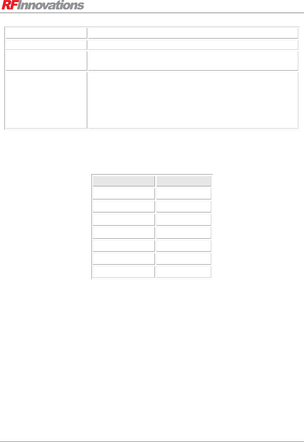
Appendix A Technical Specifications
Crescendo UHF Half-Duplex User Manual Page 57 of 78
Digital Inputs
0 - 5 V (internal 5 kiloohm pull-up)
Input Voltage
9 V to 16 V DC (negative ground)
Environmental
Specifications
Temperature: -10 ºC to +60 ºC
Humidity (max): 95% non-condensing at 50 ºC
Connectors:
Power: Phoenix PH1776508
Main Serial Port: DB9 RS-232 Female
Auxiliary Serial Port: DB9 RS-232 Female
I/O Module Connector (where present): 5-way terminal block (35mm,
screw flange, Phoenix part number 1843826)
RF: BNC Female (50 ohm nominal)
Table 19: Radio modem specifications
A.2.1 Input Current
Tx Power (dBm)
Current (mA)
Rx Only
100
0
390
20
450
27
650
30
830
36
1490
37
1700
Table 20: Nominal input current at 450 MHz, 100% Duty Cycle
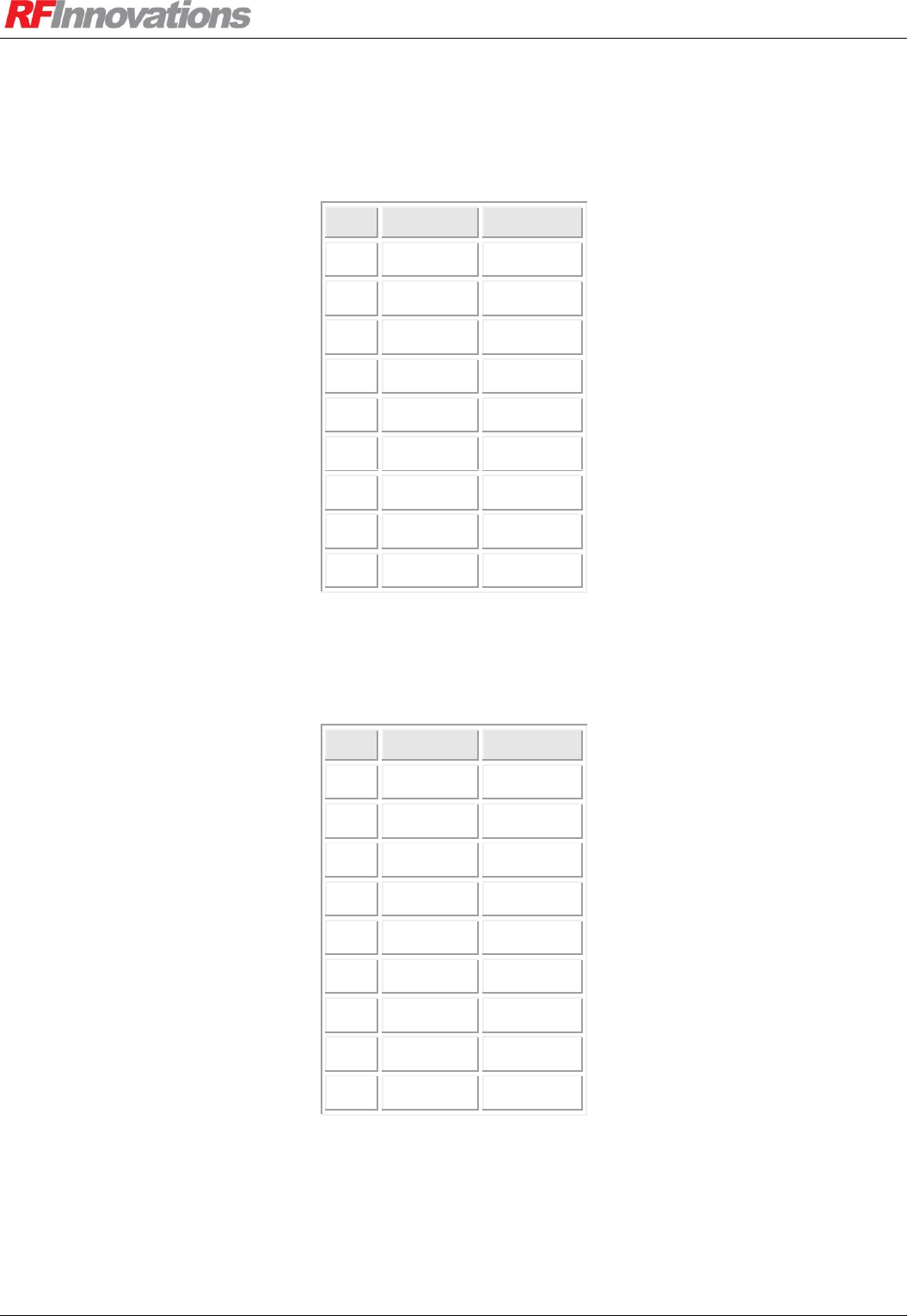
Appendix A Technical Specifications
Crescendo UHF Half-Duplex User Manual Page 58 of 78
A.3 Connector Pin Assignment
A.3.1 Main Serial Port
Pin
Function
Direction
1
DCD
Output
2
RxD
Output
3
TxD
Input
4
DTR
Input
5
GND
6
N/A
7
RTS
Input
8
CTS
Output
9
N/A
Table 21: Main connector pin assignment
A.3.2 Auxiliary Serial Port
Pin
Function
Direction
1
N/A
2
RxD
Output
3
TxD
Input
4
N/A
5
GND
6
N/A
7
N/A
8
N/A
9
N/A
Table 22: Auxiliary connector pin assignment
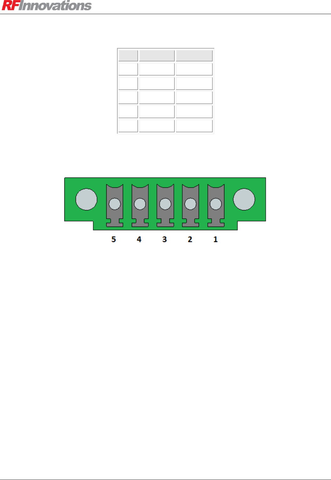
Appendix A Technical Specifications
Crescendo UHF Half-Duplex User Manual Page 59 of 78
A.3.3 I/O Module
Pin
Function
Direction
1
Input 1
Input
2
Input 2
Input
3
Input 3
Input
4
Input 4
Input
5
GND
Table 23: I/O module pin assignment
Figure 25: I/O module pin numbering

Appendix A Technical Specifications
Crescendo UHF Half-Duplex User Manual Page 60 of 78
Length
188 mm
Width
101.6 mm
Height
45.4 mm
Table 24: Dimensions
Unit Weight
700 g
Shipping Weight
850 g
Table 25: Nominal weight
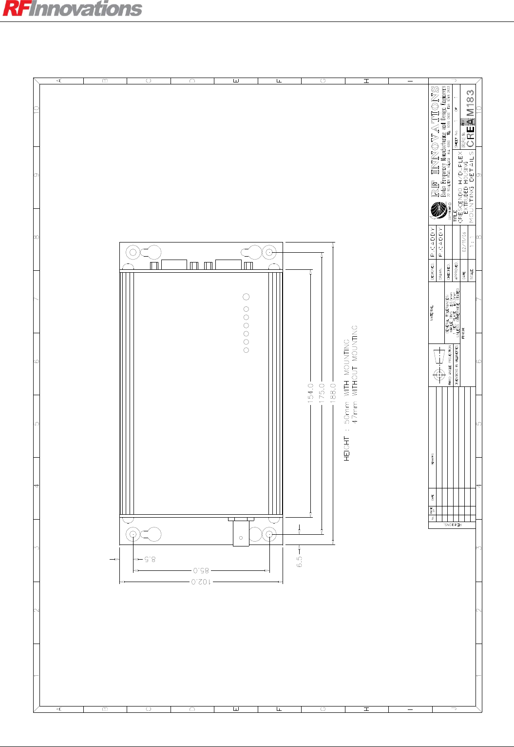
Appendix A Technical Specifications
Crescendo UHF Half-Duplex User Manual Page 61 of 78
A.3.4 Mounting Plate Dimensions
Figure 26: Mounting plate dimensions
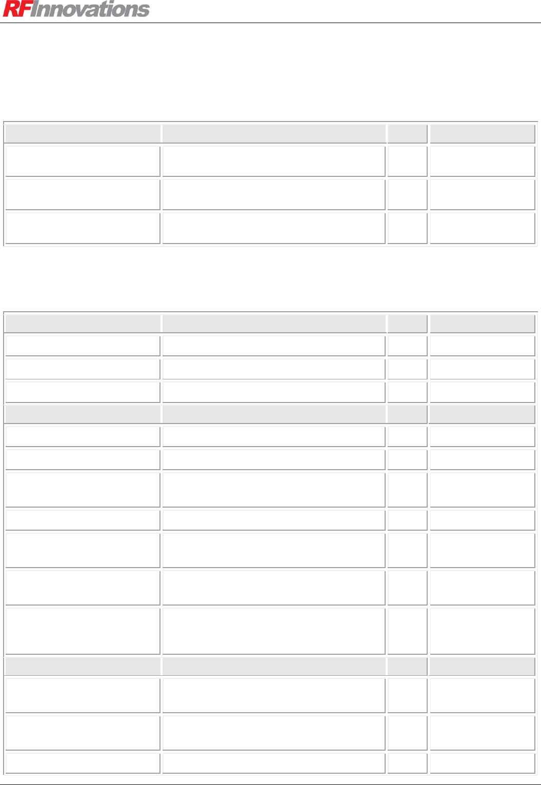
Appendix B Management Reference
Crescendo UHF Half-Duplex User Manual Page 62 of 78
Appendix B Management Reference
B.1 Main Configuration
Main
Page
AT
Product String
The product string.
I0
Manufacture Date
The date of manufacture.
I5
Serial number
The serial number of the unit.
I6
B.2 Radio Configuration
Radio
Page
AT
Address
Sets the radio local address, 0-61439
23
S51
Tx Power
The output power.
24
S45
RSSI Trip
Set the RF signal level for RF data.
24
S53
Network
Network Address
The network address
27
S50
Repeater Mode
Enables store-and-forward functionality
28
&L
Repeaters In Network
Sets the maximum number of repeaters
used to reach a destination.
25
S160
Max Packet Size
Sets the maximum packet payload.
25
S170
Broadcast Retransmissions
Sets the number of times a broadcast
packet is retransmitted
25
S38
Singlecast Retries
Sets the number of times a packet is
retried before it is discarded.
25
S41
Routing Table
Allows routing rules to be configured
30
S151:firstaddr
S152:lastaddr
S153:hopaddr
Channel
Tx Range
Shows the range of allowable Tx
frequencies.
24
Rx Range
Shows the range of allowable Rx
frequencies.
24
Channel Width
Shows the channel width of the radio.
24
I50

Appendix B Management Reference
Crescendo UHF Half-Duplex User Manual Page 63 of 78
Raster
Sets the raster to be used.
24
S57
Current Channel
Sets the current channel and
corresponding Tx/Rx frequencies to be
used.
24
S54
I/O Selects Channel
Determines whether active channel can be
selected by digital inputs.
24
S180
Channel Tx Frequency
Transmit frequency for a channel.
24
S55
Channel Rx Frequency
Receiving frequency for a channel.
24
S56
Table 26: Radio configuration
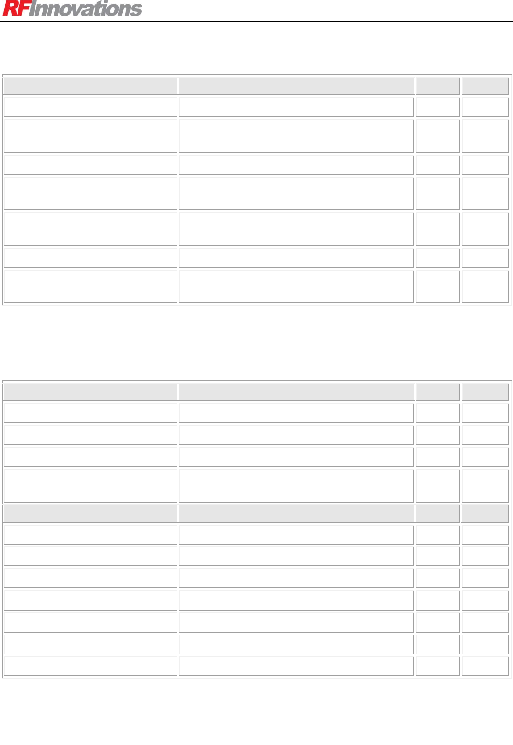
Appendix B Management Reference
Crescendo UHF Half-Duplex User Manual Page 64 of 78
B.3 Link Control Configuration and Diagnostics
Link Control
Page
AT
Data Quality
Shows the current data quality (0-255)
31
I60
Lowest Data Quality
Shows lowest data quality received so far (0-
255)
31
I61
Temperature
The temperature of the unit.
I9
Average Noise
The average RSSI level where no valid carrier
is present on the receive channel.
31
I12
Average RSSI
The average RSSI level while data is being
received.
31
I11
Last RSSI
The RSSI level for the last valid data received.
31
I31
Bad Trigger
The RSSI value for the last bad Trigger
received.
31
Table 27: Link control configuration and diagnostics
B.4 Serial Port Configuration and Diagnostics
Serial Port
Page
AT
Main Flow Control
The main port flow control operation.
17
S104
Main DCD Mode
The rule for controlling DCD.
17
S90
Main CTS Mode
The rule for controlling CTS.
17
S91
Online Timeout
The timeout used by the Follows Online CTS /
DCD mode.
17, 13
S43
Port Settings
Baud
The serial port baud rate.
17
S100
Data Bits
The serial port data bits.
17
S102
Parity
The serial port parity.
17
S101
Stop Bits
The serial port stop bits.
17
S103
Rx Packetiser Timer
The receive packetiser timer.
18
S40
Tx Packetiser Timer
The transmit packetiser timer.
18
S39
Statistics
The serial port statistics.
19
I20
Table 28: Serial port configuration and diagnostics
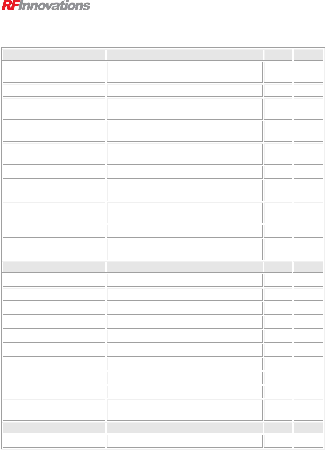
Appendix B Management Reference
Crescendo UHF Half-Duplex User Manual Page 65 of 78
B.5 Protocol Mode Configuration and Diagnostics
Protocol
Page
AT
Modbus Query
Enables configuration and diagnostic parameters
to be accessed by Modbus commands.
39
Modbus Address
The Modbus address of the radio.
39
Lead-in Count
The number of lead-in bytes the radio will discard
and not transmit over the air.
34
S73
Data timeout
The period of serial silence the radio will wait
before it stops transmitting.
34
S74
RF Link Status
The state of the RF link for the port.
41, 35,
36
I16
Mode
The selected protocol mode
34
S70
Point-to-point Destination
Address
The point-to-point partner radio address
35
S52
Start In Local Mode
Enables local command mode on the port when
the radio powers up.
36
S72
Point-to-Point Mode
Connection or packet driven mode.
35
S71
Point-to-[multi]point Receive
Mode
The receive address mode (strict or relaxed).
35
S64
Hayes Dial-up Protocol
Wait for Carrier
Number of seconds to wait for a connection.
36
S7
Auto-Answer
Whether to auto-answer dial requests.
37
S1
Rings Before Answer
Number of rings to wait before auto-answering.
37
S0
DTR Mode
Sets the action the radio takes on DTR settings.
38
&D
Echo
Whether to echo bytes in local command mode.
12
E
Responses
Enables or disables responses.
12
Q
Verbal Responses
Sets responses as either strings or numbers.
12
V
Escape Guard Time
Time to wait for the escape sequence.
36
S12
Escape Character
The escape character.
36
S2
Allow Local Mode
Enables usage of the escape sequence while in
other protocol modes (excludes data driven).
36
S3
Datagram Protocol
Footer Mode
CRC-32 or fixed.
36
S140
Table 29: Protocol mode configuration and diagnostics
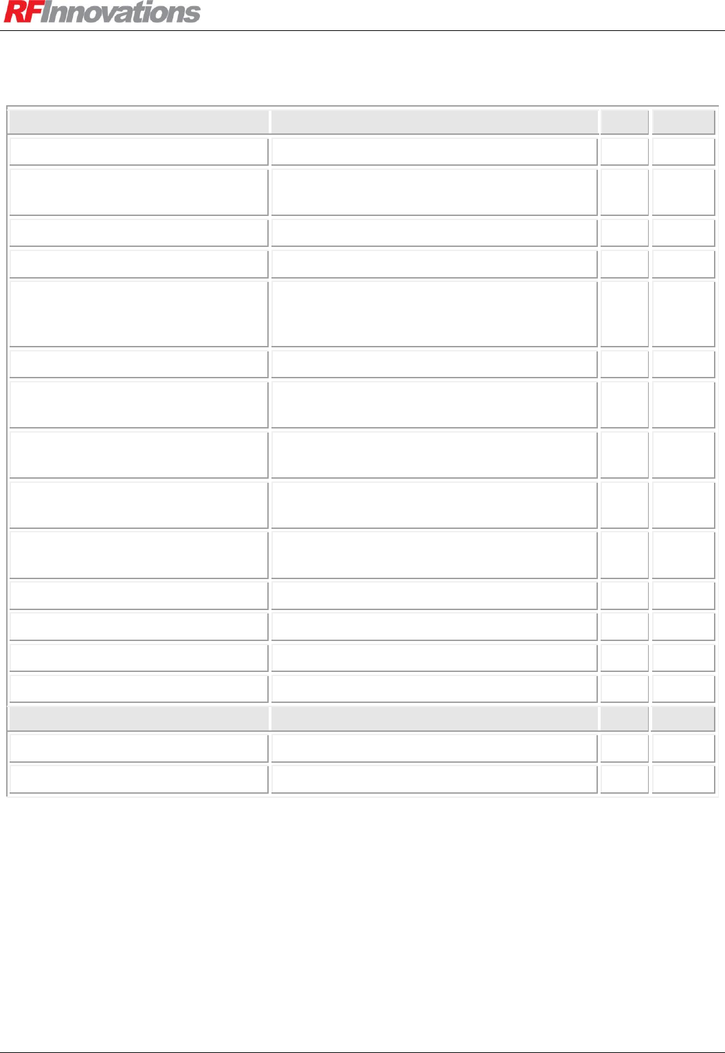
Appendix B Management Reference
Crescendo UHF Half-Duplex User Manual Page 66 of 78
B.6 Diagnostics
Diagnostics
Page
AT
Fault
The last fault that was reported.
I15
Startup Reason
Indicates if the radio started normally or due to
a watchdog reset.
EEPROM Status
The state of the EEPROM at start-up.
R10
Build Date
The date that the firmware was built.
R9
Monitor RSSI
Puts the radio in a mode when it continuously
outputs the RSSI on the current channel (can
only be used in menu).
Factory Reset
Resets all settings to factory defaults.
72
&F1
Load Configuration
Reloads all configuration from EEPROM,
discarding changes made with AT commands.
66
Z
Save Configuration
Saves all configuration changes made with AT
commands to EEPROM.
66
&W
Data Driven MAC
Performance statistics when using the data
driven serial protocol
19
Packet Driven MAC
Performance statistics when using a serial
protocol other than the data driven protocol.
19
Baseband Statistics
Baseband specific statistics.
19
Reset Data Driven Statistics
Clears all Data Driven MAC statistics
Reset Packet Driven Statistics
Clears all Packet Driven MAC statistics
Reset Baseband Statistics
Clears all baseband statistics.
&C1
Event Log
Level
The logging level.
S60
Clear Event Log
Clears the event log
Table 30: Diagnostics

Appendix C Hayes Reference
Crescendo UHF Half-Duplex User Manual Page 67 of 78
Appendix C Hayes Reference
C.1 General Commands
Command
Name
Notes
ATE
Echo
Returns 1 if Hayes echo is enabled, or 0 if echo is
disabled.
ATE0
Disables Hayes echo.
ATE1
Enables Hayes echo.
ATQ
Responses
Returns 1 if Hayes responses are enabled, or 0 if
responses are disabled.
ATQ0
Disables Hayes responses.
ATQ1
Enables Hayes responses.
ATV
Verbal Responses
Returns 1 if verbal responses are enabled, or 0 if
verbal responses are disabled.
ATV0
Disables verbal responses. Responses will all be
numeric.
ATV1
Enables verbal responses.
ATZ
Initialise
Reloads all the configuration settings.
AT&C1
Clear RF Statistics
AT&F1
Factory Reset
Performs a complete factory reset.
AT&D
Hayes DTR Mode
0: Ignore
1: Hangup on DTR Low
2: Hangup on DTR Dropped
3: Local on DTR Low
AT&D0
Sets the unit to ignore.
AT&D1
Sets the unit to hangup on DTR low.
AT&D2
Sets the unit to hangup on DTR dropped.
AT&D3
Sets the unit to go local on DTR low.
AT&L
Store-and-forward
Repeater Mode
0: Store and forward repeater disabled
1: Store and forward repeater enabled
AT&L0
Disable store-and-forward repeater.
AT&L1
Enable store-and-forward repeater.
AT&T7
Soft Reset
Reboot the radio.
AT&T8
Watchdog Reset
Trigger watchdog and cause a fault to be logged.
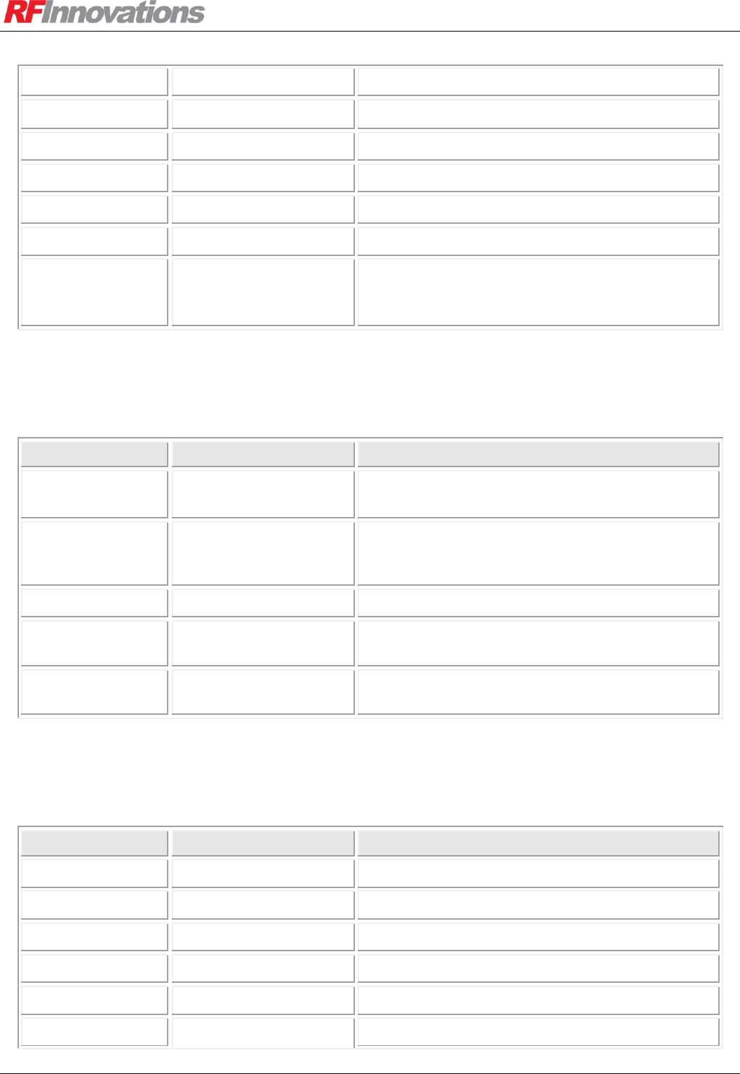
Appendix C Hayes Reference
Crescendo UHF Half-Duplex User Manual Page 68 of 78
AT&T9
Hard Reset
Restart system for programming.
AT&V
View All Registers
Outputs the value in all I and S registers.
AT&V1
View All I Registers
AT&V2
View All S Registers
AT&W
Save Configuration
Saves the current configuration to EEPROM.
AT?
Enable Menu
AT%30
Enable Cruise Control
Enables the Cruise Control on the serial port. Wait
for 10 seconds after executing with no further data
input to return to normal Hayes mode.
Table 31: Hayes general commands
C.2 Connection Management Commands
Command
Name
Notes
ATT
Traceroute
Starts a traceroute diagnostic to a destination radio.
See section 6.5.6.
ATD
ATDT
ATDP
Dial
ATA
Answer
ATH
ATH0
Hangup
ATO
ATO0
Go Online
Table 32: Hayes connection management commands
C.3 I-Registers
Command
Name
Notes
ATI5
Manufacture Date
ATI6
Serial Number
ATI9
Temperature
ATI11
Average RSSI
ATI15
Fault
ATI16[0]
RF Link Status
Returns the RF link status for the main port.
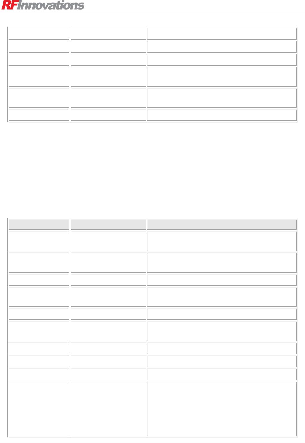
Appendix C Hayes Reference
Crescendo UHF Half-Duplex User Manual Page 69 of 78
ATI16[1]
Returns the RF link status for the auxiliary port.
ATI20[p, s]
Serial Port Statistics
ATI25[s]
Get Baseband Statistic
ATI26[s]
Get Data Driven MAC
Statistic
ATI27[s]
Get Packet Driven MAC
Statistic
ATI50
Channel Width
Table 33: Hayes I-register commands
C.4 S-Registers
All serial port configuration and status commands can be executed on either the main port or auxiliary port.
The parameter [p] that may be passed to each serial port AT command should be set to 0 for main, or 1 for
auxiliary.
Command
Name
Notes
ATS0
Rings Before Answer
Sets or returns the current number of rings before
auto-answer.
ATS1
Auto Answer
0: Disabled
1: Enabled
ATS2
Escape Character
Sets or returns the current escape character.
ATS7
Wait for Carrier
Sets or returns the number of seconds to wait for a
carrier to be established.
ATS12
Escape Guard Time
Sets or returns the escape guard time in ms.
ATS38
Broadcast
Retransmissions
ATS39
Tx Packetiser Timer
ATS40
Rx Packetiser Timer
ATS41
Singlecast Retries
ATS45
Transmit Power
0: 0 dBm
1: +20 dBm
2: +27 dBm
3: +30 dBm
4: +36 dBm
5: +37 dBm

Appendix C Hayes Reference
Crescendo UHF Half-Duplex User Manual Page 70 of 78
Command
Name
Notes
ATS50
Network Address
ATS51
Radio Address
ATS52
Point-to-point
Destination Address
ATS53
RSSI Trip
ATS54
Current Channel
First channel number is 1, unless Legacy Channel
Numbering is enabled, in which case first channel
is 0.
ATS55[c]
Channel Tx Frequency
c is the channel number. Frequency in MHz. First
channel number is 1, unless Legacy Channel
Numbering is enabled, in which case first channel
is 0.
ATS56[c]
Channel Rx Frequency
c is the channel number. Frequency in MHz. First
channel number is 1, unless Legacy Channel
Numbering is enabled, in which case first channel
is 0.
ATS60
Log Filter
0: Faults
1: Warnings
2: Status
3: Information
4: Debugging
ATS64
Point-to-[multi]point
Receive Addressing
0: Strict
1: Relaxed
ATS65
Clear Event Log
ATS70
Protocol Mode
0: Point-to-point
1: Point-to-multipoint
2: Hayes Dial-up
3: Datagram
4: Log
ATS71
Point-to-point Mode
0: Connectionless
1: Connection Based
ATS90
Main Port DCD Mode
Note that this command cannot have a [p] port
specifier.
0: Always High
1: Always Low
2: Mirrors DTR
3: Mirrors RTS
4: Follows Rx Carrier
5: Follows Tx Enable
6: Follows Online

Appendix C Hayes Reference
Crescendo UHF Half-Duplex User Manual Page 71 of 78
Command
Name
Notes
ATS91
Main Port CTS Mode
Note that this command cannot have a [p] port
specifier.
0: Always High
1: Always Low
2: Mirrors DTR
3: Mirrors RTS
4: Follows Rx Carrier
5: Follows Tx Enable
6: Follows Online
ATS92
Get Main Port DTR
Note that this command cannot have a [p] port
specifier.
0: Line is not asserted.
1: Line is asserted.
ATS93
Get Main Port RTS
Mode
Note that this command cannot have a [p] port
specifier.
0: Line is not asserted.
1: Line is asserted.
ATS100
Baud
0: 110
1: 300
2: 600
3: 1200
4: 2400
5: 4800
6: 9600
7: 14400
8: 19200
9: 38400
10:57600
11:115200
ATS101
Parity
0: None
1: Even
2: Odd
ATS102
Data Bits
0: 7
1: 8
ATS103
Stop Bits
0: 1
1: 2
ATS104
Main Port Flow Control
Note that this command cannot have a [p] port
specifier.
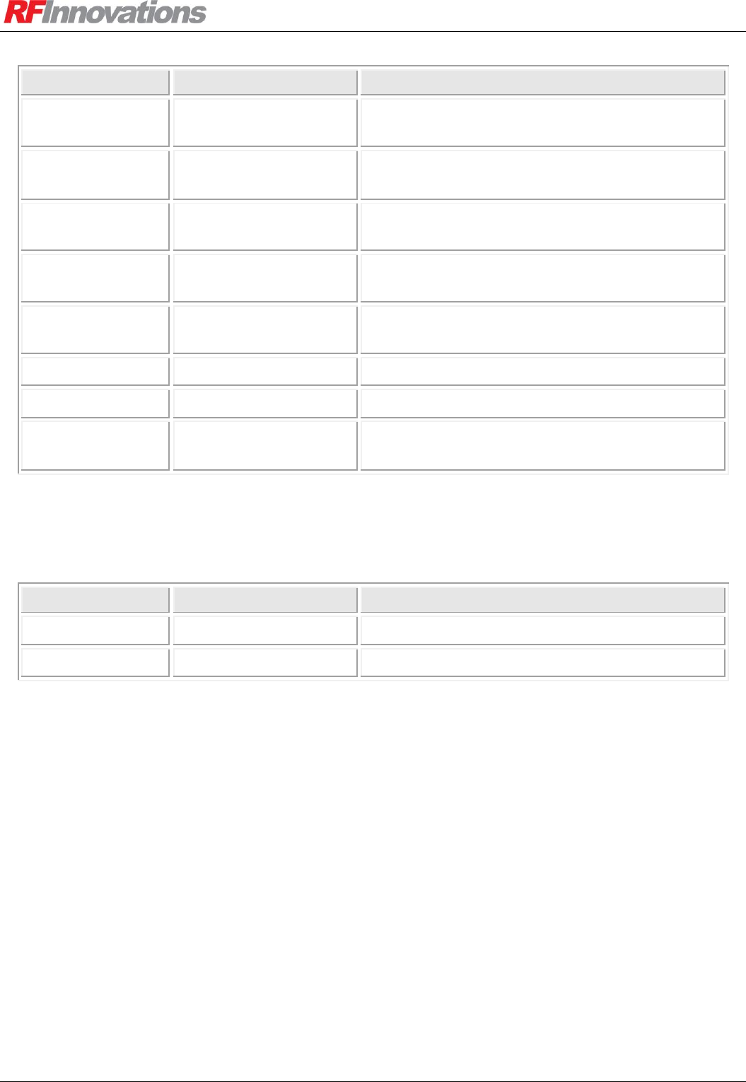
Appendix C Hayes Reference
Crescendo UHF Half-Duplex User Manual Page 72 of 78
Command
Name
Notes
0: None
2: Hardware (RTS / CTS)
ATS140
Datagram Footer Mode
0: Fixed
1: CRC-32
ATS151[a]
Routing Table Entry
First Address
ATS152[a]
Routing Table Entry
Last Address
ATS153[a]
Routing Table Hop
Address
ATS160
Repeaters in Network
ATS170
Max RF Packet Size
ATS180
I/O Selects Channel
0: Disabled
1: Enabled
Table 34: Hayes S-register commands
C.5 R-Registers
Command
Name
Notes
ATR9
Firmware Build Date
ATR10
EEPROM Status
Table 35: Hayes R-register commands
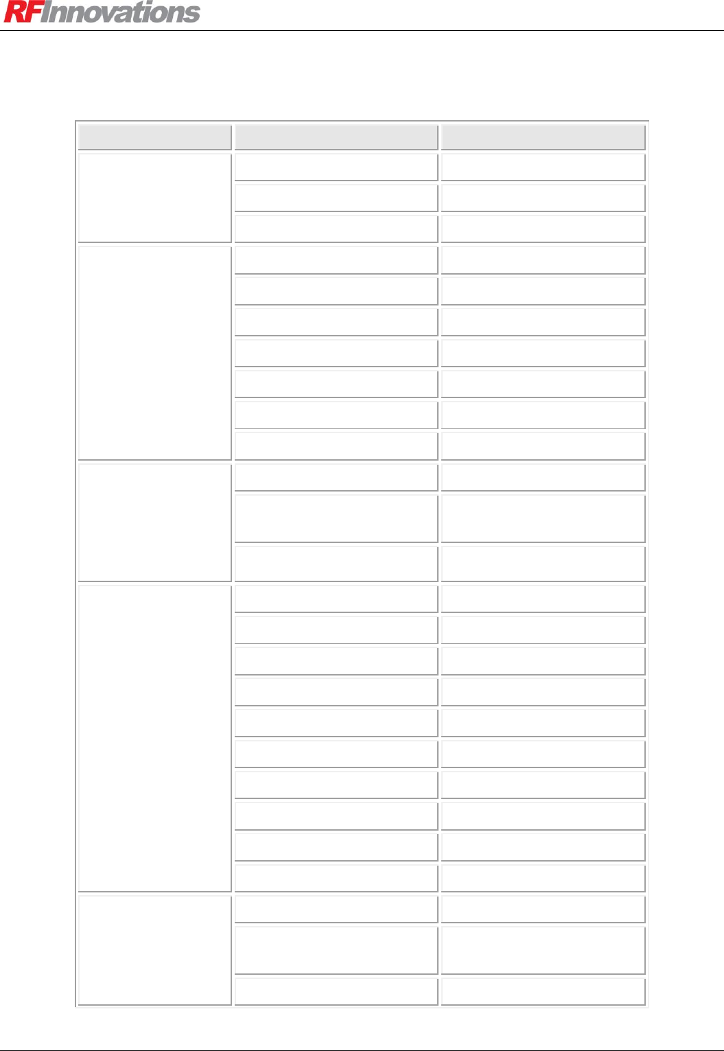
Appendix D Factory Defaults
Crescendo UHF Half-Duplex User Manual Page 73 of 78
Appendix D Factory Defaults
Group
Parameter
Default Value
Radio
Address
1000
Tx Power
30 dBm
RSSI Trip
-110
Network
Network Address
0
Store and Forward Repeater
Disabled
Repeaters in Network
0
Max Packet Size
1024 bytes
Broadcast Retransmissions
5
Singlecast Retries
5
Routing Table
<empty>
Channel
Current Channel
1
Channels (Tx and Rx)
1-16: As set by factory
(not reset with factory reset)
I/O Selects Channel
Disabled
Serial Ports
Main Flow Control
None
Main DCD Mode
Always High
Main CTS Mode
Always High
Baud
19200
Data Bits
8
Parity
None
Stop Bits
1
Rx Packetiser Timer
0 ms
Tx Packetiser Timer
0 ms
Protocol
Protocol Mapping
<empty>
Mode
Main: Data Driven
Aux: Hayes Dial-up
Point-to-point destination
20
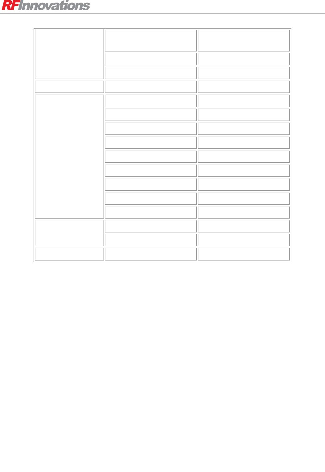
Appendix D Factory Defaults
Crescendo UHF Half-Duplex User Manual Page 74 of 78
Start In Local Mode
Main: Disabled
Aux: Enabled
Point-to-point Mode
Connection Based
Receive Addressing
Strict
Datagram
Footer Mode
CRC-32
Hayes Dial-up
Wait for Carrier
10 seconds
Auto-Answer
On
Rings Before Answer
3
DTR Mode
Ignore
Echo
On
Response
On
Verbal Responses
On
Escape Guard Time
1000 ms
Escape Guard Character
+
Data Driven
Lead-in Count
0
Data Timeout
2 ms
Event Log
Level
Information
Table 36: Factory defaults
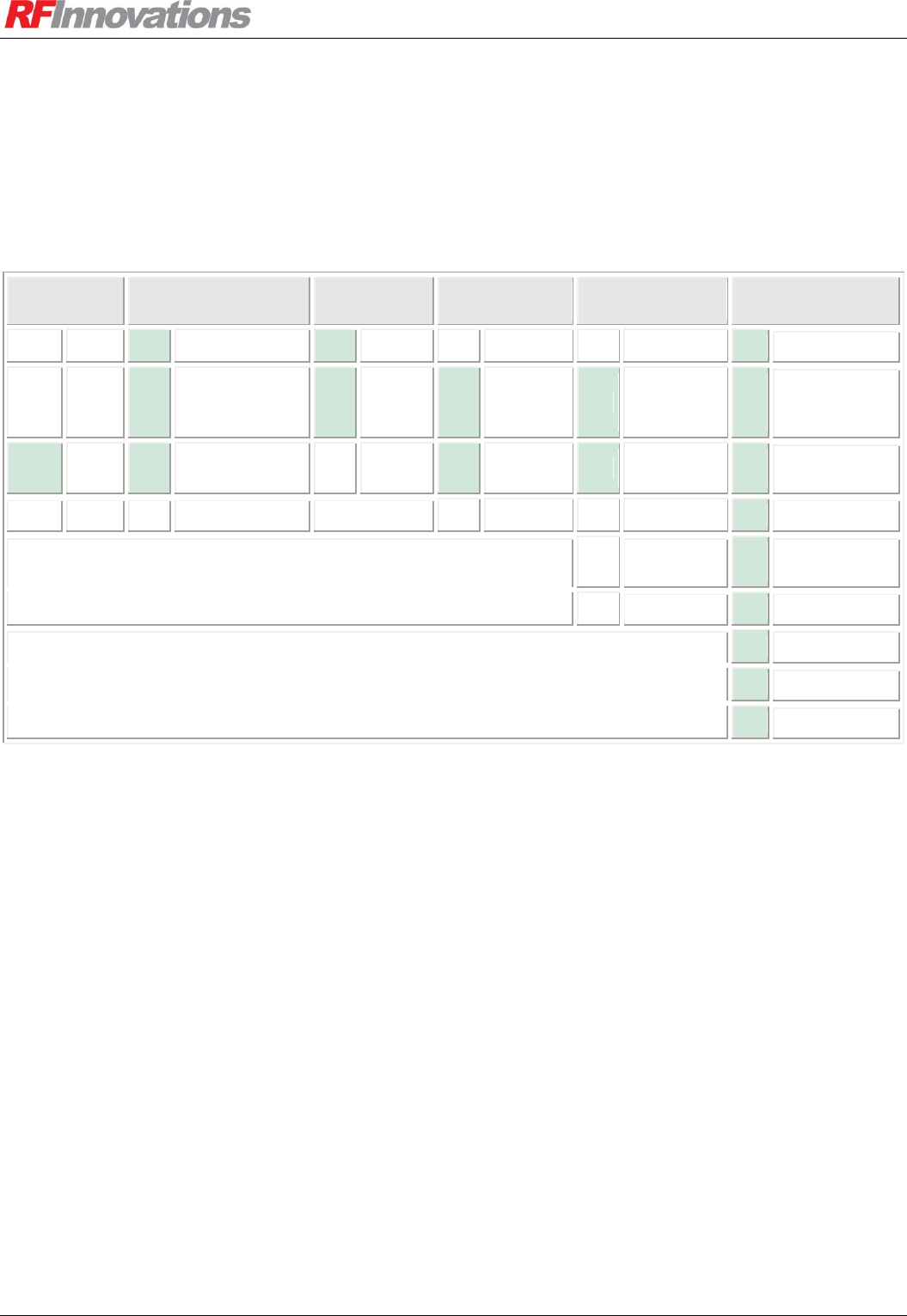
Appendix E Product Identification Table
Crescendo UHF Half-Duplex User Manual Page 75 of 78
Appendix E Product Identification Table
Table 37 shows the Crescendo product identification. The green shaded items are the available
configuration. This table should be used when ordering a Crescendo radio modem.
FREQUENCY
BAND
RF MODE
CHANNEL
WIDTH
AIR RATE
OPERATING
MODE
BANDWIDTH
150
VHF
H
Half Duplex
N
Narrow
L
1200/2400
BD
Bit-Driven
01
Custom
290
VHF
S
Half Duplex
(Separate Tx/Rx
Ports)
W
Wide
M
9600
DD
Data-Driven
02
390 – 410 MHz
450
UHF
F
Half Duplex (595F
compatible)
C
Custom
H
19200
PD
Packet-Driven
03
400 – 420 MHz
590
UHF
D
Full Duplex
C
Custom
VF
VF Only
04
410 – 430 MHz
ID
Data-Driven,
I/O Module
05
420 – 440 MHz
CC
Custom
06
430 – 450 MHz
07
440 – 460 MHz
08
450 – 470 MHz
09
460 – 480 MHz
Table 37: Crescendo product identification table
For example, the product code for a Crescendo UHF, Half Duplex, Wideband, 19200 bps, Data Driven
Radio with 400 MHz - 420 MHz bandwidth is RFI-450 HWHDD03.
Appendix F Glossary
Crescendo UHF Half-Duplex User Manual Page 76 of 78
Appendix F Glossary
ACK
Acknowledgement
ARQ
Automatic Repeat Request
BNC
British Naval Connector
CRC
Cyclic Redundancy Check
CTS
Clear To Send
DCD
Data Carrier Detect
DCE
Data Communications Equipment (radio
modem)
DTE
Data Terminal Equipment (computer device)
DTR
Data Terminal Ready
RF
Radio Frequency
RSSI
Received Signal Strength Indicator
RTS
Request To Send
Rx
Receive
Tx
Transmit
UHF
Ultra High Frequency
VHF
Very High Frequency
FER
Frame Error Rate
Table 38: Glossary

Index
Crescendo UHF Half-Duplex User Manual Page 77 of 78
Index
Addressing.......................................................................... 23
Answering .......................................................................... 37
Applications ....................................................................... 44
AT Commands ................................................................... 12
Auto-answer ....................................................................... 37
Broadcast retransmissions .................................................. 25
Button ................................................................................. 13
Channel Selection ............................................................... 24
Configuration ....................................................................... 9
Connection Based ............................................................... 35
Connectionless ................................................................... 35
Cruise Control .................................................................... 10
Data timeout ....................................................................... 65
Datagram Protocol........................................................ 39, 40
Basic Network ............................................................... 55
Diagnostics ......................................................................... 66
Dialling ............................................................................... 36
DTR Modes ........................................................................ 38
Escape Sequence ................................................................ 37
Factory Defaults ................................................................. 73
Fault ................................................................................... 14
Front Panel ......................................................................... 13
Glossary.............................................................................. 76
GUI ..................................................................................... 10
Hanging Up ........................................................................ 37
Hayes AT Commands .................................................. 12, 67
Connections ................................................................... 68
General .......................................................................... 67
I-Registers ..................................................................... 68
R-Registers .................................................................... 72
S-Registers ..................................................................... 69
Hayes Dial-up Protocol ...................................................... 36
Basic Network ............................................................... 50
Repeater Network .................................................... 47, 51
Hopping Pattern ................................................................. 27
Installation ............................................................................ 7
Introduction .......................................................................... 6
Latency ............................................................................... 22
Lead-in Count ..................................................................... 65
LEDs .................................................................................. 13
Local Mode ........................................................................ 36
Main Serial Port Status ....................................................... 14
Management Reference
Address .......................................................................... 62
Auto-Answer ................................................................. 65
Average Noise ............................................................... 64
Average RSSI ................................................................ 64
Bad Trigger ................................................................... 64
Baseband Statistics ........................................................ 66
Baud .............................................................................. 64
Broadcast Retransmissions ............................................ 62
Build Date ..................................................................... 66
Channel Width............................................................... 62
Clear Event Log ............................................................ 66
Current Channel ............................................................ 63
Data Bits ........................................................................ 64
Data Driven MAC ......................................................... 66
Data Quality .................................................................. 64
DTR Mode .................................................................... 65
Echo............................................................................... 65
EEPROM Status ............................................................ 66
Escape Character ........................................................... 65
Escape Guard Time ....................................................... 65
Factory Reset ................................................................. 66
Fault............................................................................... 66
Footer Mode .................................................................. 65
Level .............................................................................. 66
Load Configuration ....................................................... 66
Main CTS Mode ............................................................ 64
Main DCD Mode ........................................................... 64
Main Flow Control ........................................................ 64
Max Packet Size ............................................................ 62
Mode ............................................................................. 65
Monitor RSSI ................................................................ 66
Network Address ........................................................... 62
Online Timeout ............................................................. 64
Packet Driven MAC ...................................................... 66
Parity ............................................................................. 64
Point-to-[multi]point Receive Mode ............................. 65
Point-to-point Destination Address ............................... 65
Point-to-Point Mode ...................................................... 65
Repeaters In Network .................................................... 62
Reset Baseband Statistics .............................................. 66
Reset Data Driven Statistics .......................................... 66
Reset Packet Driven Statistics ....................................... 66
Responses ...................................................................... 65
RF Link Status ............................................................... 65
Rings Before Answer .................................................... 65
Routing Table ................................................................ 62
RSSI Trip ...................................................................... 62
Rx Packetiser Timer ...................................................... 64
Rx Range ....................................................................... 62
Save Configuration ........................................................ 66
Singlecast Retries .......................................................... 62
Start In Local Mode ....................................................... 65
Startup Reason............................................................... 66
Statistics ........................................................................ 64
Stop Bits ........................................................................ 64
Store and Forward Repeater .......................................... 62
Temperature .................................................................. 64
Tx Packetiser Timer ...................................................... 64
Tx Power ....................................................................... 62
Tx Range ....................................................................... 62
Verbal Responses .......................................................... 65

Index
Crescendo UHF Half-Duplex User Manual Page 78 of 78
Wait for Carrier ............................................................. 65
Manual answer ................................................................... 37
Max Packet Size ................................................................. 26
Menu .................................................................................. 11
Mode 1 ............................................................................... 13
Mode 2 ............................................................................... 14
Mode 3 ............................................................................... 14
Mode 4 ............................................................................... 14
Mode 5 ............................................................................... 14
Mounting Plate Dimensions ............................................... 61
Network Address ................................................................ 27
Network Structure .............................................................. 29
Online ................................................................................. 41
Online Timeout .................................................................. 17
Packetiser Timers ............................................................... 18
Point-to-multipoint Protocol............................................... 35
Basic Network ............................................................... 48
Modbus Network ......................................... 49, 52, 53, 54
Repeater Network ........................................ 49, 52, 53, 54
Point-to-point Networks ..................................................... 44
Point-to-point Protocol ....................................................... 35
Basic Network ............................................................... 44
Multiple Destination Network ................................. 45, 46
Product Identification Table ............................................... 75
Radio Statistics ............................................................. 31, 32
Radio Status LEDs ............................................................. 13
Relaxed Addressing............................................................ 35
Repeater ............................................................................. 28
Repeaters in Network ......................................................... 26
Retransmissions ................................................................. 25
Retries ................................................................................ 25
Routing ............................................................................... 29
Table .............................................................................. 30
RSSI ............................................................................. 14, 31
RSSI Trip ........................................................................... 24
Rx Packetiser Timer ........................................................... 18
Serial Ports ......................................................................... 16
Configuration ................................................................ 17
Connectors ..................................................................... 58
Auxiliary ................................................................... 58
Main.......................................................................... 58
Control Lines ................................................................. 17
Packetiser Timers .......................................................... 18
Statistics ........................................................................ 19
Singlecast retries ................................................................ 25
Store-and-forward Repeater ............................................... 28
Strict Addressing ................................................................ 35
Technical Specifications .................................................... 56
Radio Modem ................................................................ 56
Temperature Status ............................................................ 14
Terminal Menu References ................................................ 62
Traceroute .......................................................................... 38
Transmit Power .................................................................. 24
Tx Packetiser Timer ........................................................... 18
Tx Power ............................................................................ 14